US5302450A - Metal encapsulated solid lubricant coating system - Google Patents
Metal encapsulated solid lubricant coating systemDownload PDFInfo
- Publication number
- US5302450A US5302450AUS08/088,486US8848693AUS5302450AUS 5302450 AUS5302450 AUS 5302450AUS 8848693 AUS8848693 AUS 8848693AUS 5302450 AUS5302450 AUS 5302450A
- Authority
- US
- United States
- Prior art keywords
- metal
- powder
- coating
- solid lubricant
- particles
- Prior art date
- Legal status (The legal status is an assumption and is not a legal conclusion. Google has not performed a legal analysis and makes no representation as to the accuracy of the status listed.)
- Expired - Lifetime
Links
- 229910052751metalInorganic materials0.000titleclaimsabstractdescription99
- 239000002184metalSubstances0.000titleclaimsabstractdescription99
- 239000000314lubricantSubstances0.000titleclaimsabstractdescription67
- 239000007787solidSubstances0.000titleclaimsabstractdescription63
- 239000011248coating agentSubstances0.000titleclaimsdescription58
- 238000000576coating methodMethods0.000titleclaimsdescription58
- 239000000843powderSubstances0.000claimsabstractdescription52
- 239000002245particleSubstances0.000claimsabstractdescription39
- OKTJSMMVPCPJKN-UHFFFAOYSA-NCarbonChemical compound[C]OKTJSMMVPCPJKN-UHFFFAOYSA-N0.000claimsabstractdescription30
- 239000010439graphiteSubstances0.000claimsabstractdescription29
- 229910002804graphiteInorganic materials0.000claimsabstractdescription29
- CWQXQMHSOZUFJS-UHFFFAOYSA-Nmolybdenum disulfideChemical compoundS=[Mo]=SCWQXQMHSOZUFJS-UHFFFAOYSA-N0.000claimsabstractdescription21
- 229910052982molybdenum disulfideInorganic materials0.000claimsabstractdescription21
- 229910052961molybdeniteInorganic materials0.000claimsabstractdescription14
- WUKWITHWXAAZEY-UHFFFAOYSA-Lcalcium difluorideChemical compound[F-].[F-].[Ca+2]WUKWITHWXAAZEY-UHFFFAOYSA-L0.000claimsabstractdescription12
- 229910001634calcium fluorideInorganic materials0.000claimsabstractdescription10
- 229910052749magnesiumInorganic materials0.000claimsabstractdescription9
- 229910052759nickelInorganic materials0.000claimsabstractdescription7
- 229910052725zincInorganic materials0.000claimsabstractdescription7
- 229910052742ironInorganic materials0.000claimsabstractdescription6
- 229910052718tinInorganic materials0.000claimsabstractdescription6
- 229910015136FeMnInorganic materials0.000claimsabstractdescription4
- 229910052802copperInorganic materials0.000claimsdescription11
- 229910045601alloyInorganic materials0.000claimsdescription10
- 239000000956alloySubstances0.000claimsdescription10
- 229910052782aluminiumInorganic materials0.000claimsdescription9
- 238000005461lubricationMethods0.000claimsdescription9
- 239000000758substrateSubstances0.000claimsdescription8
- 239000000463materialSubstances0.000claimsdescription7
- 239000000374eutectic mixtureSubstances0.000claimsdescription4
- 229910052719titaniumInorganic materials0.000claimsdescription4
- 229910052710siliconInorganic materials0.000claimsdescription3
- 229910021260NaFeInorganic materials0.000claims1
- 239000007771core particleSubstances0.000abstractdescription2
- 239000003921oilSubstances0.000description20
- PQXKHYXIUOZZFA-UHFFFAOYSA-Mlithium fluorideChemical compound[Li+].[F-]PQXKHYXIUOZZFA-UHFFFAOYSA-M0.000description18
- 238000007750plasma sprayingMethods0.000description10
- 230000009467reductionEffects0.000description10
- 239000010949copperSubstances0.000description9
- 239000000446fuelSubstances0.000description9
- 239000000203mixtureSubstances0.000description9
- PXHVJJICTQNCMI-UHFFFAOYSA-NNickelChemical compound[Ni]PXHVJJICTQNCMI-UHFFFAOYSA-N0.000description8
- XAGFODPZIPBFFR-UHFFFAOYSA-NaluminiumChemical compound[Al]XAGFODPZIPBFFR-UHFFFAOYSA-N0.000description8
- RYGMFSIKBFXOCR-UHFFFAOYSA-NCopperChemical compound[Cu]RYGMFSIKBFXOCR-UHFFFAOYSA-N0.000description7
- 238000000034methodMethods0.000description7
- 229910052582BNInorganic materials0.000description6
- PZNSFCLAULLKQX-UHFFFAOYSA-NBoron nitrideChemical compoundN#BPZNSFCLAULLKQX-UHFFFAOYSA-N0.000description6
- XEEYBQQBJWHFJM-UHFFFAOYSA-NIronChemical compound[Fe]XEEYBQQBJWHFJM-UHFFFAOYSA-N0.000description6
- 238000002485combustion reactionMethods0.000description6
- 230000033001locomotionEffects0.000description6
- BDAGIHXWWSANSR-UHFFFAOYSA-Nmethanoic acidNatural productsOC=OBDAGIHXWWSANSR-UHFFFAOYSA-N0.000description6
- 229920000642polymerPolymers0.000description6
- 239000000839emulsionSubstances0.000description5
- 239000012530fluidSubstances0.000description5
- 238000009472formulationMethods0.000description5
- 239000011777magnesiumSubstances0.000description5
- 238000004519manufacturing processMethods0.000description5
- 239000002002slurrySubstances0.000description5
- 239000004593EpoxySubstances0.000description4
- 239000011230binding agentSubstances0.000description4
- 230000009969flowable effectEffects0.000description4
- 230000004927fusionEffects0.000description4
- 230000000717retained effectEffects0.000description4
- PUZPDOWCWNUUKD-UHFFFAOYSA-Msodium fluorideChemical compound[F-].[Na+]PUZPDOWCWNUUKD-UHFFFAOYSA-M0.000description4
- 239000011775sodium fluorideSubstances0.000description4
- 238000005507sprayingMethods0.000description4
- 239000011701zincSubstances0.000description4
- OSWFIVFLDKOXQC-UHFFFAOYSA-N4-(3-methoxyphenyl)anilineChemical compoundCOC1=CC=CC(C=2C=CC(N)=CC=2)=C1OSWFIVFLDKOXQC-UHFFFAOYSA-N0.000description3
- 229910000838Al alloyInorganic materials0.000description3
- 239000004215Carbon black (E152)Substances0.000description3
- KFZMGEQAYNKOFK-UHFFFAOYSA-NIsopropanolChemical compoundCC(C)OKFZMGEQAYNKOFK-UHFFFAOYSA-N0.000description3
- FYYHWMGAXLPEAU-UHFFFAOYSA-NMagnesiumChemical compound[Mg]FYYHWMGAXLPEAU-UHFFFAOYSA-N0.000description3
- OKKJLVBELUTLKV-UHFFFAOYSA-NMethanolChemical compoundOCOKKJLVBELUTLKV-UHFFFAOYSA-N0.000description3
- RTAQQCXQSZGOHL-UHFFFAOYSA-NTitaniumChemical compound[Ti]RTAQQCXQSZGOHL-UHFFFAOYSA-N0.000description3
- 230000001464adherent effectEffects0.000description3
- -1babbittChemical compound0.000description3
- 239000000919ceramicSubstances0.000description3
- 238000000151depositionMethods0.000description3
- 235000019253formic acidNutrition0.000description3
- 229930195733hydrocarbonNatural products0.000description3
- 150000002430hydrocarbonsChemical class0.000description3
- 230000008018meltingEffects0.000description3
- 238000002844meltingMethods0.000description3
- 150000002739metalsChemical class0.000description3
- 239000011148porous materialSubstances0.000description3
- 238000007790scrapingMethods0.000description3
- 229920001169thermoplasticPolymers0.000description3
- 229920001187thermosetting polymerPolymers0.000description3
- 239000011135tinSubstances0.000description3
- 239000010936titaniumSubstances0.000description3
- ITRNXVSDJBHYNJ-UHFFFAOYSA-Ntungsten disulfideChemical compoundS=[W]=SITRNXVSDJBHYNJ-UHFFFAOYSA-N0.000description3
- XLYOFNOQVPJJNP-UHFFFAOYSA-NwaterSubstancesOXLYOFNOQVPJJNP-UHFFFAOYSA-N0.000description3
- 229910000906BronzeInorganic materials0.000description2
- 229910001018Cast ironInorganic materials0.000description2
- 229920000084Gum arabicPolymers0.000description2
- ZOKXTWBITQBERF-UHFFFAOYSA-NMolybdenumChemical compound[Mo]ZOKXTWBITQBERF-UHFFFAOYSA-N0.000description2
- 241000978776Senegalia senegalSpecies0.000description2
- XUIMIQQOPSSXEZ-UHFFFAOYSA-NSiliconChemical compound[Si]XUIMIQQOPSSXEZ-UHFFFAOYSA-N0.000description2
- HCHKCACWOHOZIP-UHFFFAOYSA-NZincChemical compound[Zn]HCHKCACWOHOZIP-UHFFFAOYSA-N0.000description2
- 239000000205acacia gumSubstances0.000description2
- 235000010489acacia gumNutrition0.000description2
- 229910002065alloy metalInorganic materials0.000description2
- 238000005275alloyingMethods0.000description2
- 230000015572biosynthetic processEffects0.000description2
- IISBACLAFKSPIT-UHFFFAOYSA-Nbisphenol AChemical compoundC=1C=C(O)C=CC=1C(C)(C)C1=CC=C(O)C=C1IISBACLAFKSPIT-UHFFFAOYSA-N0.000description2
- 239000010974bronzeSubstances0.000description2
- 230000008859changeEffects0.000description2
- 238000006243chemical reactionMethods0.000description2
- 229910017052cobaltInorganic materials0.000description2
- 239000010941cobaltSubstances0.000description2
- GUTLYIVDDKVIGB-UHFFFAOYSA-Ncobalt atomChemical compound[Co]GUTLYIVDDKVIGB-UHFFFAOYSA-N0.000description2
- 239000002131composite materialSubstances0.000description2
- 239000002826coolantSubstances0.000description2
- KUNSUQLRTQLHQQ-UHFFFAOYSA-Ncopper tinChemical compound[Cu].[Sn]KUNSUQLRTQLHQQ-UHFFFAOYSA-N0.000description2
- 230000001419dependent effectEffects0.000description2
- 230000008021depositionEffects0.000description2
- 238000013461designMethods0.000description2
- 238000009499grossingMethods0.000description2
- 239000004615ingredientSubstances0.000description2
- 229910000765intermetallicInorganic materials0.000description2
- 230000001050lubricating effectEffects0.000description2
- 239000011159matrix materialSubstances0.000description2
- 229910001092metal group alloyInorganic materials0.000description2
- 229910052750molybdenumInorganic materials0.000description2
- 239000011733molybdenumSubstances0.000description2
- 229920001223polyethylene glycolPolymers0.000description2
- 238000010008shearingMethods0.000description2
- 239000010703siliconSubstances0.000description2
- HBMJWWWQQXIZIP-UHFFFAOYSA-Nsilicon carbideChemical compound[Si+]#[C-]HBMJWWWQQXIZIP-UHFFFAOYSA-N0.000description2
- 229910010271silicon carbideInorganic materials0.000description2
- 235000013024sodium fluorideNutrition0.000description2
- 239000007921spraySubstances0.000description2
- 238000001694spray dryingMethods0.000description2
- 238000012546transferMethods0.000description2
- RBORURQQJIQWBS-QVRNUERCSA-N(4ar,6r,7r,7as)-6-(6-amino-8-bromopurin-9-yl)-2-hydroxy-2-sulfanylidene-4a,6,7,7a-tetrahydro-4h-furo[3,2-d][1,3,2]dioxaphosphinin-7-olChemical compoundC([C@H]1O2)OP(O)(=S)O[C@H]1[C@@H](O)[C@@H]2N1C(N=CN=C2N)=C2N=C1BrRBORURQQJIQWBS-QVRNUERCSA-N0.000description1
- WSLDOOZREJYCGB-UHFFFAOYSA-N1,2-DichloroethaneChemical compoundClCCClWSLDOOZREJYCGB-UHFFFAOYSA-N0.000description1
- JLZLJRAXIMADMA-UHFFFAOYSA-N2,4-bis(dimethylamino)-6-[2-(dimethylamino)ethyl]phenolChemical compoundCN(C)CCC1=CC(N(C)C)=CC(N(C)C)=C1OJLZLJRAXIMADMA-UHFFFAOYSA-N0.000description1
- ZOXJGFHDIHLPTG-UHFFFAOYSA-NBoronChemical compound[B]ZOXJGFHDIHLPTG-UHFFFAOYSA-N0.000description1
- DKPFZGUDAPQIHT-UHFFFAOYSA-NButyl acetateNatural productsCCCCOC(C)=ODKPFZGUDAPQIHT-UHFFFAOYSA-N0.000description1
- VYZAMTAEIAYCRO-UHFFFAOYSA-NChromiumChemical compound[Cr]VYZAMTAEIAYCRO-UHFFFAOYSA-N0.000description1
- QPLDLSVMHZLSFG-UHFFFAOYSA-NCopper oxideChemical compound[Cu]=OQPLDLSVMHZLSFG-UHFFFAOYSA-N0.000description1
- 239000005751Copper oxideSubstances0.000description1
- 229910000599Cr alloyInorganic materials0.000description1
- 229910018274Cu2 OInorganic materials0.000description1
- 229910000990Ni alloyInorganic materials0.000description1
- GRYLNZFGIOXLOG-UHFFFAOYSA-NNitric acidChemical compoundO[N+]([O-])=OGRYLNZFGIOXLOG-UHFFFAOYSA-N0.000description1
- 229910019142PO4Inorganic materials0.000description1
- 239000004372Polyvinyl alcoholSubstances0.000description1
- 229910000831SteelInorganic materials0.000description1
- NINIDFKCEFEMDL-UHFFFAOYSA-NSulfurChemical compound[S]NINIDFKCEFEMDL-UHFFFAOYSA-N0.000description1
- ATJFFYVFTNAWJD-UHFFFAOYSA-NTinChemical compound[Sn]ATJFFYVFTNAWJD-UHFFFAOYSA-N0.000description1
- JFBZPFYRPYOZCQ-UHFFFAOYSA-N[Li].[Al]Chemical compound[Li].[Al]JFBZPFYRPYOZCQ-UHFFFAOYSA-N0.000description1
- 230000009471actionEffects0.000description1
- 230000006978adaptationEffects0.000description1
- SNAAJJQQZSMGQD-UHFFFAOYSA-Naluminum magnesiumChemical compound[Mg].[Al]SNAAJJQQZSMGQD-UHFFFAOYSA-N0.000description1
- 238000013459approachMethods0.000description1
- 230000008901benefitEffects0.000description1
- 238000007664blowingMethods0.000description1
- 229910052796boronInorganic materials0.000description1
- 230000001680brushing effectEffects0.000description1
- 239000000969carrierSubstances0.000description1
- 239000003795chemical substances by applicationSubstances0.000description1
- 229910052804chromiumInorganic materials0.000description1
- 239000011651chromiumSubstances0.000description1
- 239000000788chromium alloySubstances0.000description1
- 239000008199coating compositionSubstances0.000description1
- 239000000567combustion gasSubstances0.000description1
- 238000007906compressionMethods0.000description1
- 230000006835compressionEffects0.000description1
- 238000001816coolingMethods0.000description1
- 239000012809cooling fluidSubstances0.000description1
- 229910000431copper oxideInorganic materials0.000description1
- 230000007797corrosionEffects0.000description1
- 238000005260corrosionMethods0.000description1
- 238000005238degreasingMethods0.000description1
- 238000010586diagramMethods0.000description1
- QGBSISYHAICWAH-UHFFFAOYSA-NdicyandiamideChemical compoundNC(N)=NC#NQGBSISYHAICWAH-UHFFFAOYSA-N0.000description1
- 239000002270dispersing agentSubstances0.000description1
- 230000000694effectsEffects0.000description1
- 238000005538encapsulationMethods0.000description1
- 229920006334epoxy coatingPolymers0.000description1
- 238000005530etchingMethods0.000description1
- 239000010419fine particleSubstances0.000description1
- 239000007789gasSubstances0.000description1
- FUZZWVXGSFPDMH-UHFFFAOYSA-Nhexanoic acidChemical compoundCCCCCC(O)=OFUZZWVXGSFPDMH-UHFFFAOYSA-N0.000description1
- 238000005470impregnationMethods0.000description1
- 230000006872improvementEffects0.000description1
- 238000010348incorporationMethods0.000description1
- 239000011261inert gasSubstances0.000description1
- 229910052500inorganic mineralInorganic materials0.000description1
- 239000007788liquidSubstances0.000description1
- 238000011068loading methodMethods0.000description1
- 230000004807localizationEffects0.000description1
- 239000007769metal materialSubstances0.000description1
- 239000011707mineralSubstances0.000description1
- 235000010755mineralNutrition0.000description1
- 238000012986modificationMethods0.000description1
- 230000004048modificationEffects0.000description1
- 150000002815nickelChemical class0.000description1
- 229910000480nickel oxideInorganic materials0.000description1
- 229910017604nitric acidInorganic materials0.000description1
- 229920000620organic polymerPolymers0.000description1
- 230000003647oxidationEffects0.000description1
- 238000007254oxidation reactionMethods0.000description1
- GNRSAWUEBMWBQH-UHFFFAOYSA-NoxonickelChemical compound[Ni]=OGNRSAWUEBMWBQH-UHFFFAOYSA-N0.000description1
- 238000010422paintingMethods0.000description1
- NBIIXXVUZAFLBC-UHFFFAOYSA-KphosphateChemical compound[O-]P([O-])([O-])=ONBIIXXVUZAFLBC-UHFFFAOYSA-K0.000description1
- 239000010452phosphateSubstances0.000description1
- 239000004033plasticSubstances0.000description1
- 229920003023plasticPolymers0.000description1
- 239000002491polymer binding agentSubstances0.000description1
- 229920002451polyvinyl alcoholPolymers0.000description1
- 239000012255powdered metalSubstances0.000description1
- 239000002994raw materialSubstances0.000description1
- 239000002904solventSubstances0.000description1
- 235000015096spiritNutrition0.000description1
- 239000010959steelSubstances0.000description1
- 238000013517stratificationMethods0.000description1
- 229910052717sulfurInorganic materials0.000description1
- 239000011593sulfurSubstances0.000description1
- 238000007751thermal sprayingMethods0.000description1
- 239000004416thermosoftening plasticSubstances0.000description1
- 238000012800visualizationMethods0.000description1
Images


Classifications
- C—CHEMISTRY; METALLURGY
- C23—COATING METALLIC MATERIAL; COATING MATERIAL WITH METALLIC MATERIAL; CHEMICAL SURFACE TREATMENT; DIFFUSION TREATMENT OF METALLIC MATERIAL; COATING BY VACUUM EVAPORATION, BY SPUTTERING, BY ION IMPLANTATION OR BY CHEMICAL VAPOUR DEPOSITION, IN GENERAL; INHIBITING CORROSION OF METALLIC MATERIAL OR INCRUSTATION IN GENERAL
- C23C—COATING METALLIC MATERIAL; COATING MATERIAL WITH METALLIC MATERIAL; SURFACE TREATMENT OF METALLIC MATERIAL BY DIFFUSION INTO THE SURFACE, BY CHEMICAL CONVERSION OR SUBSTITUTION; COATING BY VACUUM EVAPORATION, BY SPUTTERING, BY ION IMPLANTATION OR BY CHEMICAL VAPOUR DEPOSITION, IN GENERAL
- C23C4/00—Coating by spraying the coating material in the molten state, e.g. by flame, plasma or electric discharge
- C23C4/04—Coating by spraying the coating material in the molten state, e.g. by flame, plasma or electric discharge characterised by the coating material
- Y—GENERAL TAGGING OF NEW TECHNOLOGICAL DEVELOPMENTS; GENERAL TAGGING OF CROSS-SECTIONAL TECHNOLOGIES SPANNING OVER SEVERAL SECTIONS OF THE IPC; TECHNICAL SUBJECTS COVERED BY FORMER USPC CROSS-REFERENCE ART COLLECTIONS [XRACs] AND DIGESTS
- Y10—TECHNICAL SUBJECTS COVERED BY FORMER USPC
- Y10T—TECHNICAL SUBJECTS COVERED BY FORMER US CLASSIFICATION
- Y10T29/00—Metal working
- Y10T29/49—Method of mechanical manufacture
- Y10T29/49229—Prime mover or fluid pump making
- Y10T29/4927—Cylinder, cylinder head or engine valve sleeve making
- Y10T29/49272—Cylinder, cylinder head or engine valve sleeve making with liner, coating, or sleeve
- Y—GENERAL TAGGING OF NEW TECHNOLOGICAL DEVELOPMENTS; GENERAL TAGGING OF CROSS-SECTIONAL TECHNOLOGIES SPANNING OVER SEVERAL SECTIONS OF THE IPC; TECHNICAL SUBJECTS COVERED BY FORMER USPC CROSS-REFERENCE ART COLLECTIONS [XRACs] AND DIGESTS
- Y10—TECHNICAL SUBJECTS COVERED BY FORMER USPC
- Y10T—TECHNICAL SUBJECTS COVERED BY FORMER US CLASSIFICATION
- Y10T428/00—Stock material or miscellaneous articles
- Y10T428/29—Coated or structually defined flake, particle, cell, strand, strand portion, rod, filament, macroscopic fiber or mass thereof
- Y10T428/2982—Particulate matter [e.g., sphere, flake, etc.]
- Y10T428/2991—Coated
Definitions
- This inventionrelates to the art of fluid lubricated metal wear interfaces or contacts, and more particularly to the use of anti-friction solid film lubricants for such interfaces modified to withstand high unit scraping or bearing loads at high temperatures while functioning with either full or partial fluid lubrication.
- U.S. Pat. No. 1,654,509 (1927)discloses use of powder graphite trapped or covered by a metal binder (i.e., iron, aluminum, bronze, tin, lead, babbitt, or copper) to form a thick coating; all of the metal is heated to at least a thermoplastic condition by melting or arc spraying to bury the graphite.
- a metal binderi.e., iron, aluminum, bronze, tin, lead, babbitt, or copper
- One of the coauthors of this inventionhas previously disclosed certain solid lubricants operable at high temperatures, but designed for interfacing with ceramics, not metals, and generally at low load applications in the absence of any liquids.
- One solid lubricant disclosedcomprised graphite and boron nitride in a highly viscous thermoplastic polymer binder spread in a generous volume onto a seal support comprised of nickel and chromium alloy. The formulation was designed to provide a hard coating which softens at the surface under load while at or above the operating temperature and functioning only under dry operating conditions.
- Thermoplastic polymer based formulationsare unsatisfactory in meeting the needs of a loaded engine component, such as a cylinder bore, because the unit loads are significantly higher (approaching 500 psi), and the surface temperatures are higher, causing scraping.
- Another solid lubricant disclosedwas halide salts or MoS 2 (but not as a combination) in a nickel, copper, or cobalt binder; the coating, without modifications, would not be effective in providing a stable and durable anti-friction coating for the walls of an internal combustion cylinder bore, because the formulations were designed to operate under dry conditions and against ceramics, primarily lithium aluminum silicate and magnesium aluminum silicate, and, thus, the right matrix was not used nor was the right combination of solid lubricants used.
- formulationswere designed to produce a ceramic compatible oxide (e.g., copper oxide or nickel oxide) through partial oxidation of the metal in the formulation. These systems were designed to permit as much as 300-500 microns wear. In the cylinder bore application, only 5-10 micron wear is permitted.
- a ceramic compatible oxidee.g., copper oxide or nickel oxide
- the encapsulationpromotes improved fusion to the light metal bore surface and promotes a lace-like network of fusion metal between particles.
- Another objectis to provide a coating composition that economically reduces friction for high temperature applications, particularly along a cylinder bore wall at temperatures above 700° F. when oil lubrication fails or in the presence of oil flooding (while successfully resisting conventional or improved piston ring applied loads).
- Another object of this inventionis to provide a lower cost method of making coated cylinder walls by rapidly applying a coating by plasma spraying requiring less energy and at reduced or selected areas of the bore wall while achieving excellent adherence and precise deposition with a larger powder grain size, the method demanding less rough and machine finishing of the bore surface.
- Still another objectis to provide a coated aluminum alloy cylinder wall product for an engine that (i) assists in achieving reduced piston system friction and reduced piston blow-by, all resulting in improved vehicle fuel economy of 2-4% for a gasoline powered vehicle; (ii) reduces hydrocarbon emissions; and (iii) reduces engine vibration by at least 20% at wide-open throttle conditions at moderate speeds (i.e., 1000-3000 rpm).
- the inventionin a first aspect, is a thermally sprayable powder, having powder grains comprising: (a) a core of solid lubricant particles comprising at least graphite and MoS 2 ; and (b) a thin, soft metal shell encapsulating such core.
- Additional powder grainscan comprise other solid lubricants of the group consisting of hexagonal BN, LiF, CaF 2 , WS 2 , and eutectic mixtures of LiF/CaF 2 or LiF/NaF 2 ; additional powder grains can comprise hard, wear-resistant particles selected from the group consisting of SiC, NiCrAl, and intermetallic compounds such as FeWNiVCr, NiCrMoVW, DeCrMoWV, CoFeNiCrMoWV, NiCrMoV, and CoMoCrVW (known as lave phase.
- the soft metal for the shellis selected from the group consisting of Ni, Co, Cu, Zn, Sn, Mg, and Fe.
- the inventionin another aspect is a solid lubricant coating system for a metal wear interface subject to high temperatures and wet lubrication, comprising: (a) particles of oil-attracting solid lubricants comprised of at least graphite and MoS 2 , (b) soft metal shells encapsulating the particles and being fused together to form a network of grains constituting a coating fusably adhered to the metal interface, the coating having a porosity of 2-10% by volume.
- the coatinghas a deposited thickness in the range of 40-250 microns, and is desirably honed to a thickness of about 25-175 microns.
- the inventionin still another aspect is a method of making an anti-friction coating on a metal surface subject to sliding wear, comprising: (a) forming an encapsulated powder having grains comprising essentially a core of solid lubricants of graphite and MoS 2 , and a thin shell of fusable soft metal; (b) plasma spraying the powder onto a light metal surface to form a coating; and (c) finish-smoothing of the coating to a uniform thickness of about 25-175 microns.
- the light metal surfaceis constituted of a metal or alloyed metal selected from the group consisting of aluminum, magnesium, and titanium, the light metal surface being cleansed to freshly expose the light metal or metal alloy just prior to plasma spraying.
- Yet another aspect of this inventionis an engine block having one or more anti-friction coated cylinder bore walls, comprising: (a) a metal engine block having at least one metal cylinder wall; (b) a coating of grains fused to the cylinder bore wall, the grains each being comprised of solid lubricant particles encapsulated within a soft metal shell, the shells being fused together to form a network with limited porosity, the solid lubricant comprising graphite and MoS 2 ; and (c) wet oil lubrication retained within the porosity of the coating.
- the soft metal of the coatingwill have a hardness no greater than 50 Rc (preferably Rc 20-30); the soft metal may additionally comprise a small amount of alloy metal adherently compatible with the cylinder bore wall metal.
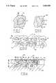
- FIG. 1is a highly enlarged view of one type of powder grain embodying this invention
- FIG. 2is a view like FIG. 1, depicting another powder grain useful with this invention
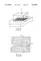
- FIG. 3is a schematic microscopic view of a segment of the as-deposited coating system of this invention.
- FIG. 4is a view like that of FIG. 3, the coating having been honed and used in a sliding friction application;
- FIG. 5is a schematic representation of the forces that influence coulomb friction
- FIG. 6is a highly enlarged microscopic view in cross-section of interfacing surfaces showing the irregularities of normal surfaces that affect coulomb friction;
- FIG. 7is a view similar to FIG. 6 showing the incorporation of solid films on the interfacing surfaces that affect coulomb friction;
- FIG. 8is a graphical illustration of the onset of plastic flow of surface films as a function of stress and temperature
- FIG. 9is a graphical illustration of surface energy (hardness) as a function of temperature for surface films
- FIG. 10is a graphical illustration of the coefficient of friction for block graphite as a function of time
- FIG. 11is a graphical illustration of the coefficient of friction and also of wear as a function of time for the coating system of this invention tested at the temperature of 500° F.;
- FIG. 12is a block diagram showing schematically the steps involved in the method aspect of this invention.
- FIG. 13is an enlarged sectional view of a portion of the liner in position for being installed in a cylinder block bore;
- FIG. 14is a schematic illustration of the mechanics involved in reciprocating a piston within a cylinder bore showing the travel of the piston rings which promote a loading on the cylinder bore coating system;
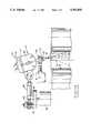
- FIG. 15is a view of the coating apparatus for depositing at high temperatures a plasma coating on a cylinder bore shown in cross-section;
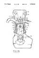
- FIG. 16is a cross-sectional illustration of an internal combustion engine containing the product of this invention showing one coated cylinder bore in its environment for reducing the total engine friction, vibration, and fuel consumption for the operation of such engine.
- the coating systemcannot rely on graphite or any one lubricant by itself, but rather upon a specific combination of solid lubricant particles encapsulated in soft metal shells that are easily fusable to each other and to the metal of the sliding interface, while retaining a desired porosity.
- the inventive systemcomprises a layer A of powder grains adhered to a metal substrate or wall 10, each grain possessing a core 11 of solid lubricant particles and a soft metal shell 12 fused to adjacent shells at contact areas 13 resulting in a fused network that possess pores 14.
- the solid lubricant particlesmust comprise at least graphite and MoS 2 , respectively present in the coating A, in amounts of, by weight, 30-70% and 30-90% of the lubricant core.
- these other solid lubricant particlesare present in the coating they should be present in the amount of about 5-20% by weight of the lubricant cores.
- the cores of certain particlesmay also be constituted of hard, wear-resistant particles 15, such as selected from the group consisting of silicon carbide, FeCrAl, NiCrAl, or FeCrMn steel and lave phases such as intermetallic compounds of FeWNiVCr, NiCrMoVW, DeCrMoWV, CoFeNiCrMoWV, NiCrMoV, and CoMoCrVW.
- the wear-resistant particlesshould be present in a minor amount controlled to be in the range of 5-25% by weight of the total cores.
- Such wear-resistant particles 15, in such controlled amountfacilitate the following function: when uniformly distributed in submicron size particulates in the grain matrix, they act as load carriers and, with proper honing, produce adjacent relieved areas that retain oil and solid lubricant reservoirs.
- the powderuseful as a raw material in creating the coating system, is comprised of powder grains 16 containing a core of solid lubricant (see FIG. 1).
- the grains 16have a core 17 of solid lubricant surrounded by an encapsulating soft metal shell 18 having a thickness 19 of about 5-40 microns, a volume ratio of the shell to the core in the range of 50:50 to 90:10, and a weight ratio of the shell to the lubricant core in the range of 70:30 to 95:5.
- the average grain size of the solid lubricant core grainsis in the range of about 2-10 microns, and the hardness of the soft metal shell is no greater than Rc 40, preferably Rc 20.
- the soft metal shellsare stable up to a temperature of at least 1200° F. when the soft metal shell is selected from the group described above.
- Powder grains 20have hard, wear-resistant core particles 21 (see FIG. 2). Such grains have the wear-resistant core 21 comprised of the materials described above, encapsulated by a soft metal shell 22 (selected as a metal or metal alloy from Ni, Co, Cu, Zn, Sn, Mg, and Fe). Such grains also contribute to the reduction of friction since such metals oxidize on exposure to high temperature; the oxides, such as NiO, CoO, or Cu 2 O, have an inherent low coefficient of friciton.
- the thickness 23 of the soft metal shellis in the range of about 5-40 microns or 70-80% of the radial cross-section.
- the average grain size of the wear-resistant grains 20is in the range of 0.2-5.0 microns, the volume ratio of the shell to the core is about 95:5 to 80:20, and the weight ratio is about 95:5 to 70:30.
- the encapsulated solid lubricant particlesmay be created by a treatment wherein the solid lubricants are placed in a molten bath of the soft metal and stirred, and the slurry is then comminuted to form the encapsulated lubricant particles 16.
- the powdermay also be made alternatively by spray drying; to this end, a water-based slurry of very fine particles of soft metal and of the solid lubricants is prepared.
- the slurryis blended with 0.5-1.5% by weight water soluble organic binder such as gum arabic and/or polyvinyl alcohol or carbowax.
- the blended slurryis then atomized by hot spraying into a hot circulating air chamber at or about 300° F.
- a well-known method of the latteris hydrometallurgical deposition developed and commercially practiced by Skerritt-Gordon of Canada.
- the preferred coatingwhen operatively used, will have a glazed or polished outer surface 24 as a result of engine start-up use or as a result of honing of the deposited particles along a honing line 26 (see FIG. 3).
- the coatingwill have a predetermined desirable amount of pores 14 which retain fluid oil for additional lubrication.
- the solid lubricantswill be smeared or spread across the honed or polished surface 24 as a result of operative use at the sliding interfaces.
- Friction in an oil-bathed environmentwill be dependent partly upon fluid friction and the oil film (layers in the fluid sheared at different velocities, commonly referred to as hydrodynamic friction), and, more importantly, dependent on dry or coulomb friction between contacting solid, rigid bodies (also referred to as boundary friction). Dry friction is tangential and opposed to the direction of sliding interengagement. As shown in FIG. 5, there is a visualization of the mechanical action of friction. The weight of a block imposes a normal force N on table C that is spread across several load forces N-1 at each interengaging hump 27 (see FIG. 6) (attributable to the interatomic bonds of the metal at the surface).
- the composite of all the tangential components of the small reaction forces F-1 at each of the interengaged humps 27is the total friction force F.
- the humpsare the inherent irregularities or asperities in any surface on a microscopic scale. When the interengaging surfaces are in relative motion, the contacts are more nearly along the tops of the humps and therefore the tangential reaction forces will be smaller. When the bodies are at rest, the coefficient of friction will be greater. Friction is influenced by the deformation and tearing of dry surface irregularities, hardness of the interengaged surfaces, and the presence of surface film such as oxides or oils. As a result, actual friction will be different from idealized perfect contact friction and will depend upon the ratio between shear and yield stresses of the interengaged surfaces.
- the presence of a film on each of the interengaging surfaceswill serve to change the coefficient of friction depending upon the shear and yield stress capacities of the films and their relative hardness.
- Such filmsprovide for shearing or sliding of boundary layers within the film to reduce friction.
- shearingis localized to essentially the areas where the humps provide hard support for the films. This localization reduces friction further.
- Frictionis also influenced significantly by temperature because high local temperatures can influence adhesion at the contact points.
- the critical stress for slipgoes down, which increases the actual area of contact surface for the same applied load, thereby increasing friction.
- the hardness (E)goes down.
- the influence of temperatureis particularly evident on graphite, as shown in FIG. 10.
- the coefficient of friction for block graphiterapidly increases to above 0.4 at 500° F. and above 0.5 at 800° F., and even higher at 1000° F.
- the coefficient of friction for graphite at 400° F. or lowerbecomes generally uniform at below 0.05. Contrast this with the coefficient of friction performance and wear performance of the coating system of this invention represented in FIG. 11. It should be noted that the coefficient of friction generally uniformly stays below 0.1, and wear is generally uniform at about 0.001"/100 hours at 500° F. (see FIG. 11).
- the coating for FIG. 11comprises only particles of graphite and boron nitride in a temperature stable polymer.
- At least graphite and molybdenum disulfidemust be present in the solid lubricant particles in amount of 5-30% by weight of the coating.
- Graphiteas earlier indicated, is effective as a solid lubricant only up to temperatures around 400° F., and possesses very poor load bearing capability such as that experienced by a piston ring scraping against the graphite itself.
- Molybdenum disulfideshould be present in an amount of 30-100% by weight of the solid lubricants, and, most importantly, is effective in increasing the load bearing capability as well as the temperature stability of the mixture up to a temperature of at least 580° F., but will break down into molybdenum and sulfur at temperatures in excess of 580° F. in air or nonreducing atmospheres.
- Molybdenum disulfidereduces friction in the absence of oil or in the presence of oil, and, most importantly, supports loads of at least 10 psi at such high temperatures. Molybdenum disulfide is also an oil attractor and is very useful in this invention, which must deal with wet lubrication.
- Boron nitridewhen selected, should be present in an amount of 5-50% by weight of the solid lubricants, and increases the stability of the mixture up to temperatures as high as 700° F. and concurrently stabilizes the temperature for the ingredients of molybdenum disulfide and graphite. Boron nitride is an effective oil attractor.
- Calcium difluoride and lithium fluorideare oil attractors, and are stable up to the respective temperatures of 1500° F. and 1200° F. and resist loads of up to 50 psi or higher. These solid lubricants yield a dry coefficient of friction of 0.1-0.2.
- Porosityallows wet oil to be retained in the pores of the coating as an impregnant during operation of the sliding contacts, particularly when the contacts are between a piston and a cylinder bore wall of an engine.
- the temperature stability of the coatingis important because typical engine cylinder bore walls will experience, at certain zones thereof and under certain engine operating conditions such as failure of coolant or oil pump, temperatures as high as 700° F. even though the hottest zone of the cylinder bore surface in the combustion chamber under normal operating conditions is only about 540° F.
- the optimum solid lubricant mixturewill contain lubricants beyond the graphite and molybdenum disulfide.
- the coefficient of friction for the coating grains in the as-deposited conditionwill be in the range of 0.07-0.08 at room temperature and a coefficient of friction as low as 0.03 at 700° F.
- the coating systemmay further include an over-layer of a thermoset polymer emulsion containing more solid lubricants.
- the solid lubricantshould comprise particles of at least two of graphite, MoS 2 , and BN.
- the thermoset polymermay be comprised of a thermoset epoxy, such as bisphenol A present in an amount of 25-70% of the polymer, such epoxy being of the type that cross-links and provides hydrocarbon and water vapor transfer to graphite while attracting oil.
- the polymeralso should contain a curing agent present in an amount of about 2-5% of the polymer such as dicyandiamide; the polymer may also contain a dispersing agent present in an amount of 0.3-1.5% such as 2, 4, 6 tri dimethylamino ethyl phenol.
- the emulsionmay comprise mineral spirits or butyl acetate that suspend the particles of solid lubricant and polymer.
- the emulsionmay be applied to the substrate or engine bore wall by any variety of techniques, at room temperature, such as emulsion spraying, painting such as by roller, or a tape which carries the emulsion.
- the soft metal of the powder shellsmay incorporate other metal alloying ingredients that are particularly compatible and adherent to the substrate or interface metal material. For example, it would be difficult to fusably adhere pure copper shells to an aluminum substrate; an alloy addition of 4-5% by weight aluminum to the shell metal promotes the needed fusion. It may be desirable to add 3-7% by weight of such alloying metal to the shell metal to promote fusion adhesion.
- the comprehensive method of making coated surfacescomprises the steps: (a) forming an encapsulated powder having grains comprising a solid lubricant core of graphite and MoS 2 , and a thin shell of fusable soft metal; (b) plasma spraying the powder onto a cleansed or freshly exposed light metal surface to form a coating; and (c) finish-smoothing of the coating to a thickness of about 25-60 microns.
- Plasma sprayed powder(i) will form a controlled porosity that allows for impregnation of wet oil; (ii) the encapsulated powder grains create asperities in the surface such that, when honed, the edges of the shell metal provide a smaller localized area of hard supporting asperities where boundary layer shear will take place in the smeared solid lubricant thereover to further reduce friction (similar to microgrooving), and (ii) the adherent metal network created as a result of melting only the outer skin of the soft metal shells during plasma spraying.
- the liner 30would be preferably constituted of the same material as that of the parent bore surface 31.
- the linercan be any metal that has a higher strength as the metal of the parent bore wall; this is often achieved by making an alloy of the metal used for the parent bore wall.
- C-355 or C-356 aluminum alloys for the linerare stronger than the 319 aluminum alloy commonly used for aluminum engine blocks.
- the linermust have generally thermal conductivity and thermal expansion characteristics essentially the same as the block.
- only the liner 30is coated interiorly at least at the upper region 32, as will be described subsequently, and the liner then assembled to the parent bore by either being frozen to about a temperature of -40° F.
- the parent boremay be heated to 270° F. while the liner is retained at room temperature, or possibly a combination of the two procedures.
- a shrink-fitis obtained by placing the liner in such differential temperature condition within the parent bore.
- the lineris coated at 33 (at room temperature) on its exterior surface with a copper flake epoxy mixture, the epoxy being of the type described for use in coating.
- the copper flake within such epoxy coatingassures not only an extremely solid bond between the liner and the light metal parent bore, but also increases the thermal transfer therebetween on a microscopic scale.
- Plasma spraying of the flowable powderis carried out to form an adherent porous layer of powder grains, the powder consisting of particles of solid lubricant encapsulated in a soft metal shell.
- the flowable powdercan be and often is a composite of the solid film lubricant and the soft metal powder produced by spray drying in which a combustible, ash-free, organic binder (such as 1% carbowax) and/or 0.5% gum arabic are used to produce the slurry from which the spray-dried powder is produced.
- the coatingis honed to a thin thickness 34 of about 25-60 microns to expose the core solid lubricants at 35 as well as present shell edges 36 which additionally provide lubricating qualities (see FIG. 4).
- the coatingis plasma sprayed onto the substrate in a deposited thickness range of about 40-140 microns.
- the substrate surfaceis preferably cleansed to provide fresh metal prior to plasma spraying, or is given a phosphate pretreatment.
- the surfaceis prepared by degreasing with OSHA approved solvent, such as ethylene dichloride, followed by rinsing with isopropyl alcohol.
- OSHA approved solventsuch as ethylene dichloride
- the surfaceis grit blasted with clean grit.
- the surfacecan be cleaned by etching with dilute HF and followed by dilute HNO 3 and then washed and rinsed. Wire brushing also helps to move the metal around without burnishing.
- the flowable powder useful for such plasma sprayingpreferably has an average particle size in the range of 20-75 microns, but for practical high volume production, such range should be restricted to 30-55 microns. Grains of 30-55 microns are freely flowable, which is necessary for feeding a plasma gun. If less than 30 microns, the powder will not flow freely. If greater than 55 microns, stratification will occur in the coating lacking uniform comingling of the particles. This does not mean that particle sizes outside such range must be scraped for an econimic loss; rather, the finer particles can be agglomerated with wax to the desired size and oversized particles can be ball-mixed to the desired size. Thus, all powder grains can be used.
- the solid lubricantswhich form the core of such encapsulated grains, are of the previously described class of graphite, molybdenum disulfide, and additionally may contain calcium fluoride, sodium fluoride, lithium fluoride, boron nitride, and tungsten disulfide.
- the soft metal shellis selected form the class of nickel, boron, cobalt, and iron or alloys of such selected metal.
- the location of conventional sliding piston rings 37moves linearly along the bore wall 31 a distance 38.
- the locus of the piston ring contact with the coatingis moved by the crank arm 39 during an angle representing about 60° of crank movement. This distance is about one-third of the full linear movement 40 of the piston rings (between top dead center--TDC, and bottom dead center--BDC).
- the distance 38represents the hot zone of the bore wall where lubrication can vary and the bore wall is most susceptible to drag and piston slap, and which is the source of a significant amount of engine friction losses while causing scuffing of the bore wall in case of wet lubricant failure.
- an overlayer of an organic polymer with solid lubricantover the shortened coating as well as the rest of the bore.
- a discontinuity or stepmay be created between the shortened coating and the parent bore wall; such a step can cause piston ring instability. Honing of the step reduces its severity, but the overlayer will eliminate or reduce any step.
- Plasma sprayingmay be carried out by equipment, as illustrated in FIG. 15, using a spray gun 41 having a pair of interior electrodes 42, 43 that create an arc through which powdered metal and inert gas are introduced to form a plasma.
- the powder metalmay be introduced through a supply line 44 connected to a slip ring 45 that in turn connects to a powder channel 46 that delivers to the nozzle 47.
- the plasmaheats the powder, being carried therewith, along the shells of the powder only.
- the gunis carried on an articulating arm 48 which is moved in a combined circular linear movement by a journal 49 carried on an eccentric positioner 51 which in turn is carried on a rotating disc 50 driven by a motor 52.
- the nozzle 47 of the gunis entrained in a fixed swivel journal 53 so that the spray pattern 54 is moved both annularly as well as linearly up and down the bore surface 55 as a result of the articulating motion of the gun.
- the productis an engine block 60 having one or more anti-friction coated cylinder bore walls 61, comprising: a coating 62 of powder grains fused to the cylinder bore wall 61, the grains being comprised of at least solid lubricant particles encapsulated within a soft metal shell, said shells being fused together to form a network with limited porosity, the solid lubricant comprising graphite and MoS 2 ; and wet oil lubrication retained within the porosity of the coating.
- the soft metal of the coatingshould have a hardness no greater than 60 Rc.
- the metal of the cylinder wallis preferably selected from the group of aluminum, titanium, magnesium, and alloys of such metals with copper, zinc, or silicon.
- the soft metalagain may additionally comprise a small amount of alloy metal adherently compatible with the cylinder bore wall metal.
- Such productis characterized by a reduction in engine friction resulting from reduction of piston system friction of at least 25% because of the reduction in boundary layer friction as well as the ability to operate the engine with a near zero piston/cylinder bore clearance. Furthermore, such product provides for a reduction in engine hydrocarbon emissions by at least 25% because of the adaptation of the piston ring designs, disclosed in concurrently filed patent applications, and thereby reduce the top land crevice volume.
- the blow-by of the engineis reduced also by about 25% because of the near zero clearance combined with the piston ring design just cited.
- the temperature of the coolant used to maintain proper temperature of the enginecan be reduced by 20° F. because a significantly lower viscosity oil can be used with such change.
- the oil temperaturecan be reduced by at least 50° F. when coupled with the avoidance of tar deposit formation on the combustion chamber surfaces, and an increase in the compression ratio of the engine by at least one with attendant improvement in fuel economy and power.
- coated blockin accordance with this invention, is the ability for resisting formic acid, formed when using flex fuels containing methanol.
- an enginewould have its surfaces degrade at 20,000 miles or greater as a result of the formation of formic acid under a peculiar set of engine conditions with such flex fuels.
- the coated bore wallsas herein, such resistance to formic acid corrosion is eliminated.
- the coated productobtains greater accuracy of roundness within the cylinder bore as the conventional rings ride thereagainst, contributing to the reduction in blow-by and friction as mentioned earlier. Friction reduction is obtained due to a reduction in the boundary friction component as well as the reduction in the boundary/dry friction coefficient itself.
- the coated blockplays an important role in the overall operation of engine efficiency.
- the blockhas an interior cooling jacket 63 along its sides and cooperates to receive a head 64 containing intake and exhaust passages 65, 66 opened and closed by intake and exhaust valves 67, 68 operated by a valve train 69 actuated by camshafts 70.
- the combustible gasesare ignited by spark ignition 71 located centrally of the combustion chamber 72 to move the piston 73, which in turn actuates a connecting rod 74 to turn a crankshaft 75 rotating within a crank case 76. Oil is drawn from the crank case 76 and splashed within the interior of the block to lubricate and bathe the piston 73 during its reciprocal movement therein.
- the cooling fluidcirculates about the cylinder bore wall to extract heat therefrom, which influences the efficiency of the engine by reducing the heat input into the air/fuel charge during the intake stroke, and thus increases volumetric efficiency as well as power and fuel economy.
Landscapes
- Chemical & Material Sciences (AREA)
- Engineering & Computer Science (AREA)
- Mechanical Engineering (AREA)
- Plasma & Fusion (AREA)
- Chemical Kinetics & Catalysis (AREA)
- Materials Engineering (AREA)
- Physics & Mathematics (AREA)
- Metallurgy (AREA)
- Organic Chemistry (AREA)
- Coating By Spraying Or Casting (AREA)
- Cylinder Crankcases Of Internal Combustion Engines (AREA)
- Lubricants (AREA)
- Pistons, Piston Rings, And Cylinders (AREA)
Abstract
Description
Claims (20)
Priority Applications (10)
| Application Number | Priority Date | Filing Date | Title |
|---|---|---|---|
| US08/088,486US5302450A (en) | 1993-07-06 | 1993-07-06 | Metal encapsulated solid lubricant coating system |
| US08/125,719US5315970A (en) | 1993-07-06 | 1993-09-24 | Metal encapsulated solid lubricant coating system |
| US08/133,412US5358753A (en) | 1993-07-06 | 1993-09-24 | Method of making an anti-friction coating on metal by plasma spraying powder having a solid lubricant core and fusable metal shell |
| AU69791/94AAU6979194A (en) | 1993-07-06 | 1994-06-23 | Metal encapsulated solid lubricant coating system |
| DE69421078TDE69421078T2 (en) | 1993-07-06 | 1994-06-24 | COATING SYSTEM MADE OF SOLID LUBRICANT ENCLOSED IN METAL |
| JP7503882AJPH08512342A (en) | 1993-07-06 | 1994-06-24 | Metal-encapsulated solid lubricant coating system |
| CA002166184ACA2166184A1 (en) | 1993-07-06 | 1994-06-24 | Metal encapsulated solid lubricant coating system |
| EP94921703AEP0707621B1 (en) | 1993-07-06 | 1994-06-24 | Metal encapsulated solid lubricant coating system |
| PCT/GB1994/001365WO1995002023A1 (en) | 1993-07-06 | 1994-06-24 | Metal encapsulated solid lubricant coating system |
| MX9404901AMX9404901A (en) | 1993-07-06 | 1994-06-28 | SOLID LUBRICATING COATING SYSTEM, ENCAPSULATED IN METAL. |
Applications Claiming Priority (1)
| Application Number | Priority Date | Filing Date | Title |
|---|---|---|---|
| US08/088,486US5302450A (en) | 1993-07-06 | 1993-07-06 | Metal encapsulated solid lubricant coating system |
Related Child Applications (2)
| Application Number | Title | Priority Date | Filing Date |
|---|---|---|---|
| US08/125,719DivisionUS5315970A (en) | 1993-07-06 | 1993-09-24 | Metal encapsulated solid lubricant coating system |
| US08/133,412DivisionUS5358753A (en) | 1993-07-06 | 1993-09-24 | Method of making an anti-friction coating on metal by plasma spraying powder having a solid lubricant core and fusable metal shell |
Publications (1)
| Publication Number | Publication Date |
|---|---|
| US5302450Atrue US5302450A (en) | 1994-04-12 |
Family
ID=22211654
Family Applications (3)
| Application Number | Title | Priority Date | Filing Date |
|---|---|---|---|
| US08/088,486Expired - LifetimeUS5302450A (en) | 1993-07-06 | 1993-07-06 | Metal encapsulated solid lubricant coating system |
| US08/133,412Expired - LifetimeUS5358753A (en) | 1993-07-06 | 1993-09-24 | Method of making an anti-friction coating on metal by plasma spraying powder having a solid lubricant core and fusable metal shell |
| US08/125,719Expired - LifetimeUS5315970A (en) | 1993-07-06 | 1993-09-24 | Metal encapsulated solid lubricant coating system |
Family Applications After (2)
| Application Number | Title | Priority Date | Filing Date |
|---|---|---|---|
| US08/133,412Expired - LifetimeUS5358753A (en) | 1993-07-06 | 1993-09-24 | Method of making an anti-friction coating on metal by plasma spraying powder having a solid lubricant core and fusable metal shell |
| US08/125,719Expired - LifetimeUS5315970A (en) | 1993-07-06 | 1993-09-24 | Metal encapsulated solid lubricant coating system |
Country Status (8)
| Country | Link |
|---|---|
| US (3) | US5302450A (en) |
| EP (1) | EP0707621B1 (en) |
| JP (1) | JPH08512342A (en) |
| AU (1) | AU6979194A (en) |
| CA (1) | CA2166184A1 (en) |
| DE (1) | DE69421078T2 (en) |
| MX (1) | MX9404901A (en) |
| WO (1) | WO1995002023A1 (en) |
Cited By (36)
| Publication number | Priority date | Publication date | Assignee | Title |
|---|---|---|---|---|
| US5484662A (en)* | 1993-07-06 | 1996-01-16 | Ford Motor Company | Solid lubricant and hardenable steel coating system |
| US5506055A (en)* | 1994-07-08 | 1996-04-09 | Sulzer Metco (Us) Inc. | Boron nitride and aluminum thermal spray powder |
| US5523006A (en)* | 1995-01-17 | 1996-06-04 | Synmatix Corporation | Ultrafine powder lubricant |
| EP0716158A1 (en)* | 1994-12-09 | 1996-06-12 | Ford Motor Company Limited | Method of making engine blocks with coated cylinder bores |
| US5593740A (en)* | 1995-01-17 | 1997-01-14 | Synmatix Corporation | Method and apparatus for making carbon-encapsulated ultrafine metal particles |
| DE19548718C1 (en)* | 1995-12-23 | 1997-05-28 | Daimler Benz Ag | Cylinder liner for motor vehicle IC-engine |
| FR2753992A1 (en)* | 1996-10-02 | 1998-04-03 | Westaim Technologies Inc | WEAR JOINT ASSEMBLY |
| CN1059223C (en)* | 1998-10-08 | 2000-12-06 | 中国科学院兰州化学物理研究所 | High temperature anti-sticky Lubricant coating material |
| US20030228483A1 (en)* | 2002-06-07 | 2003-12-11 | Petr Fiala | Thermal spray compositions for abradable seals |
| US6783746B1 (en) | 2000-12-12 | 2004-08-31 | Ashland, Inc. | Preparation of stable nanotube dispersions in liquids |
| US20040202861A1 (en)* | 2002-09-30 | 2004-10-14 | Tsuyoshi Itsukaichi | Thermal spray powder and process for producing the same as well as method for spraying the same |
| US20060000351A1 (en)* | 2004-06-30 | 2006-01-05 | Schenkel Jerry L | Piston for an engine |
| US20060208151A1 (en)* | 2005-03-16 | 2006-09-21 | Diamond Innovations, Inc. | Wear and texture coatings for components used in manufacturing glass light bulbs |
| US20060213326A1 (en)* | 2005-03-28 | 2006-09-28 | Gollob David S | Thermal spray feedstock composition |
| US20070009731A1 (en)* | 2005-03-16 | 2007-01-11 | Dumm Timothy F | Lubricious coatings |
| US20070275267A1 (en)* | 2006-05-26 | 2007-11-29 | Sulzer Metco Venture, Llc. | Mechanical seals and method of manufacture |
| US20080145554A1 (en)* | 2006-12-14 | 2008-06-19 | General Electric | Thermal spray powders for wear-resistant coatings, and related methods |
| KR100867905B1 (en)* | 2001-03-28 | 2008-11-10 | 미쓰비시 마테리알 피엠지 가부시키가이샤 | Copper-based sintered alloy bearing and motor fuel pump |
| US20090304943A1 (en)* | 2006-03-20 | 2009-12-10 | Sulzer Metco Venture Llc | Method for Forming Ceramic Containing Composite Structure |
| US20090301718A1 (en)* | 2008-06-06 | 2009-12-10 | Belgin Baser | System, Method and Apparatus for Enhanced Friction Reduction In Gravel Pack Operations |
| US20100203254A1 (en)* | 2008-05-23 | 2010-08-12 | United Technologies Corporation | Dispersion strengthened ceramic thermal barrier coating |
| DE102009030649A1 (en)* | 2009-06-25 | 2010-12-30 | Rwe Power Ag | Power station boiler for fluidized-bed combustion plant, has boiler wall provide with multiple parts, which exhibit thermal coating as wear protective measure, where thermal coating is partially laid in boiler wall |
| WO2012131164A1 (en)* | 2011-03-28 | 2012-10-04 | Teknologian Tutkimuskeskus Vtt | Thermally sprayed coating |
| WO2014013326A3 (en)* | 2012-07-19 | 2014-03-20 | Lincoln Global, Inc. | Hot-wire consumable to provide self-lubricating weld or clad |
| DE102012112394A1 (en)* | 2012-12-17 | 2014-06-18 | Dr. Ing. H.C. F. Porsche Aktiengesellschaft | Method for manufacturing coated component used in seat of motor car, involves coating region of to-be-coated surface of coated component made of magnesium material by performing thermal spraying process |
| US20140230692A1 (en)* | 2011-07-25 | 2014-08-21 | Eckart Gmbh | Methods for Substrate Coating and Use of Additive-Containing Powdered Coating Materials in Such Methods |
| EP3293357A1 (en)* | 2016-09-08 | 2018-03-14 | Siemens Aktiengesellschaft | Turbine blade base with coating |
| WO2019148066A1 (en)* | 2018-01-29 | 2019-08-01 | Purdue Research Foundation | Compositions for use as lubricants in die casting methods of using the same, and products produced therewith |
| CN110904402A (en)* | 2019-12-04 | 2020-03-24 | 中国第一汽车股份有限公司 | Self-lubricating antifriction coating and spraying method |
| FR3089523A1 (en)* | 2018-12-06 | 2020-06-12 | Renault S.A.S | Method for manufacturing a coating of a metal matrix composite material on a part for a motor vehicle |
| CN113502182A (en)* | 2021-07-08 | 2021-10-15 | 暨南大学 | A nano-rod-shaped magnesium hydroxysilicate/molybdenum disulfide composite material and its preparation method and application |
| EP3954869A1 (en)* | 2020-08-14 | 2022-02-16 | Raytheon Technologies Corporation | Coating for a blade root/disk interface and coated blade root/disk interface |
| US11697880B2 (en) | 2016-08-16 | 2023-07-11 | Seram Coatings As | Thermal spraying of ceramic materials comprising metal or metal alloy coating |
| CN116555695A (en)* | 2023-05-05 | 2023-08-08 | 中国第一汽车股份有限公司 | A kind of low-friction coating for aluminum alloy cylinder body and preparation method thereof |
| CN117089117A (en)* | 2023-10-17 | 2023-11-21 | 季华实验室 | Graphite hybrid microcapsules and preparation methods, fluorine-based materials and preparation methods |
| US20240011452A1 (en)* | 2020-03-02 | 2024-01-11 | Briggs & Stratton, Llc | Internal combustion engine with reduced oil maintenance |
Families Citing this family (64)
| Publication number | Priority date | Publication date | Assignee | Title |
|---|---|---|---|---|
| US5536022A (en)* | 1990-08-24 | 1996-07-16 | United Technologies Corporation | Plasma sprayed abradable seals for gas turbine engines |
| US5749331A (en)* | 1992-03-23 | 1998-05-12 | Tecsyn, Inc. | Powdered metal cylinder liners |
| SE501469C2 (en)* | 1993-06-30 | 1995-02-20 | Saab Automobile | Cylinder liner supporting device |
| DE4406191A1 (en)* | 1994-02-25 | 1995-09-07 | Ks Aluminium Technologie Ag | Plain bearing |
| US5976704A (en)* | 1994-03-01 | 1999-11-02 | Ford Global Technologies, Inc. | Composite metallizing wire and method of using |
| EP0677652B1 (en)* | 1994-03-18 | 1998-12-02 | Yamaha Hatsudoki Kabushiki Kaisha | Linerless engine cylinder block |
| US5648122A (en)* | 1994-09-28 | 1997-07-15 | Ford Motor Company | Using electrical discharge surface preparation for thermal coatings |
| US5671532A (en)* | 1994-12-09 | 1997-09-30 | Ford Global Technologies, Inc. | Method of making an engine block using coated cylinder bore liners |
| US5629091A (en)* | 1994-12-09 | 1997-05-13 | Ford Motor Company | Agglomerated anti-friction granules for plasma deposition |
| JP3483965B2 (en)* | 1994-12-26 | 2004-01-06 | ヤマハ発動機株式会社 | Sliding contact structure of internal combustion engine and molding method thereof |
| DE59506236D1 (en)* | 1995-02-02 | 1999-07-22 | Sulzer Innotec Ag | Non-slip composite coating |
| US5566450A (en)* | 1995-03-16 | 1996-10-22 | Ford Motor Company | Flexibly making engine block assemblies |
| JP3502689B2 (en)* | 1995-03-23 | 2004-03-02 | ヤマハ発動機株式会社 | Plating cylinder block and plating method thereof |
| EP0754847B1 (en)* | 1995-07-20 | 1999-05-26 | Spx Corporation | Method of providing a cylinder bore liner in an internal combustion engine |
| US5573814A (en)* | 1995-10-30 | 1996-11-12 | Ford Motor Company | Masking cylinder bore extremities from internal thermal spraying |
| JP3707795B2 (en)* | 1995-11-13 | 2005-10-19 | ジーエムアイシー,コーポレイション | Tool forming by thermal spraying |
| DE19605946C1 (en)* | 1996-02-17 | 1997-07-24 | Ae Goetze Gmbh | Cylinder liner for internal combustion engines and their manufacturing process |
| US5711118A (en)* | 1996-05-15 | 1998-01-27 | W.S. Molnar Company | Method of manufacturing an anti-slip flooring product and anti-slip flooring article |
| US5958521A (en)* | 1996-06-21 | 1999-09-28 | Ford Global Technologies, Inc. | Method of depositing a thermally sprayed coating that is graded between being machinable and being wear resistant |
| US5691004A (en)* | 1996-07-11 | 1997-11-25 | Ford Global Technologies, Inc. | Method of treating light metal cylinder bore walls to receive thermal sprayed metal coatings |
| JPH10184914A (en)* | 1996-12-26 | 1998-07-14 | Teikoku Piston Ring Co Ltd | Combination of piston ring and cylinder liner |
| JP3537286B2 (en)* | 1997-03-13 | 2004-06-14 | 株式会社三協精機製作所 | Sintered oil-impregnated bearing and motor using the same |
| US5820938A (en)* | 1997-03-31 | 1998-10-13 | Ford Global Technologies, Inc. | Coating parent bore metal of engine blocks |
| CA2207579A1 (en) | 1997-05-28 | 1998-11-28 | Paul Caron | A sintered part with an abrasion-resistant surface and the process for producing it |
| DE19809659C1 (en)* | 1998-03-06 | 1999-09-23 | Federal Mogul Burscheid Gmbh | Process for the production of piston rings |
| DE19909887A1 (en)* | 1998-04-03 | 1999-10-07 | Wella Ag | Forming sliding surfaces and/or shearing edges with a wear-reducing hard material on a base material |
| US6197370B1 (en)* | 1999-07-09 | 2001-03-06 | Ford Global Technologies, Inc. | Coating cylinder bores with ultra thin solid lubricant phase |
| DE19937934A1 (en)* | 1999-08-11 | 2001-02-15 | Bayerische Motoren Werke Ag | Cylinder crankcase, method for manufacturing the cylinder liners therefor and method for manufacturing the cylinder crankcase with these cylinder liners |
| US6363787B1 (en)* | 1999-12-13 | 2002-04-02 | Bechtel Bwxt Idaho Llc | Apparatus and method for measuring the thickness of a coating |
| DE10032577A1 (en)* | 2000-07-05 | 2002-01-24 | Bosch Gmbh Robert | Radial piston pump |
| US6408812B1 (en) | 2000-09-19 | 2002-06-25 | The Lubrizol Corporation | Method of operating spark-ignition four-stroke internal combustion engine |
| US6449842B1 (en)* | 2000-09-28 | 2002-09-17 | Total Seal, Inc. | Powder for piston-ring installation |
| KR100391307B1 (en)* | 2001-06-04 | 2003-07-16 | 한라공조주식회사 | Method for preparing a solid film lubricant |
| DE10153720C2 (en)* | 2001-10-31 | 2003-08-21 | Daimler Chrysler Ag | Cylinder crankcase with a cylinder liner and casting tool |
| JP4369757B2 (en)* | 2002-01-18 | 2009-11-25 | 株式会社リケン | Thermal spray piston ring |
| DE10225299A1 (en)* | 2002-06-07 | 2003-12-18 | Bayerische Motoren Werke Ag | Divided motor vehicle stabilizer has swivel motor with swivel motor gear provided as curved path gear and has curved path carriers that include grooves with coupling element that is led over liners provided in grooves |
| US6808756B2 (en)* | 2003-01-17 | 2004-10-26 | Sulzer Metco (Canada) Inc. | Thermal spray composition and method of deposition for abradable seals |
| US20040226547A1 (en)* | 2003-02-07 | 2004-11-18 | Johann Holzleitner | Plasma coating for cylinder liner and method for applying the same |
| US20050061734A1 (en)* | 2003-09-22 | 2005-03-24 | Alltrista Zinc Products, L.P. | Anti-corrosive engine oil system components |
| US20050065042A1 (en)* | 2003-09-22 | 2005-03-24 | Alltrista Zinc Products, L.P., An Indiana Limited Partnership | Anti-corrosive engine oil system components |
| US8114821B2 (en)* | 2003-12-05 | 2012-02-14 | Zulzer Metco (Canada) Inc. | Method for producing composite material for coating applications |
| KR20050104174A (en)* | 2004-04-28 | 2005-11-02 | 모딘코리아 유한회사 | Device for fixation of door on hvac for automobile |
| FR2872884B1 (en)* | 2004-07-07 | 2006-11-10 | Snecma Moteurs Sa | METHOD FOR PROTECTING CONTACT SURFACES BETWEEN TWO METALLIC PARTS BENEFITING FROM SUCH PROTECTION |
| KR100655366B1 (en) | 2005-07-04 | 2006-12-08 | 한국과학기술연구원 | Coating agent with heat resistance, abrasion resistance, low friction and coating method |
| AT502630B1 (en)* | 2005-10-21 | 2008-01-15 | Miba Sinter Austria Gmbh | COMPONENT, PARTICULARLY FORM PART, WITH A COATING |
| CA2560030C (en)* | 2005-11-24 | 2013-11-12 | Sulzer Metco Ag | A thermal spraying material, a thermally sprayed coating, a thermal spraying method an also a thermally coated workpiece |
| KR20070067802A (en)* | 2005-12-23 | 2007-06-29 | 재단법인 포항산업과학연구원 | Thermal spray composition for swash plate for automobile and manufacturing method of swash plate for automobile air conditioner using the same |
| KR20070067801A (en)* | 2005-12-23 | 2007-06-29 | 재단법인 포항산업과학연구원 | Thermal spray composition for swash plate for automobile and manufacturing method of swash plate for automobile air conditioner using the same |
| FR2896012B1 (en)* | 2006-01-06 | 2008-04-04 | Snecma Sa | ANTI-WEAR DEVICE FOR A TURNBUCKLE COMPRESSOR VARIABLE TUNING ANGLE GUIDING PIVOT PIVOT |
| US7665440B2 (en)* | 2006-06-05 | 2010-02-23 | Slinger Manufacturing Company, Inc. | Cylinder liners and methods for making cylinder liners |
| TWM317591U (en)* | 2006-08-16 | 2007-08-21 | Ya Hsin Ind Co Ltd | Projection screen |
| US20080166950A1 (en)* | 2007-01-10 | 2008-07-10 | Fricso Ltd. | Tribological surface and lapping method and system therefor |
| PL2229467T3 (en) | 2007-12-07 | 2012-11-30 | Applied Nano Surfaces Sweden Ab | Manufacturing of low-friction elements |
| US8137747B2 (en) | 2008-07-30 | 2012-03-20 | Honeywell International Inc. | Components, turbochargers, and methods of forming the components |
| US8389129B2 (en) | 2010-07-09 | 2013-03-05 | Climax Engineered Materials, Llc | Low-friction surface coatings and methods for producing same |
| US8038760B1 (en) | 2010-07-09 | 2011-10-18 | Climax Engineered Materials, Llc | Molybdenum/molybdenum disulfide metal articles and methods for producing same |
| FR2971319A1 (en)* | 2011-02-03 | 2012-08-10 | Peugeot Citroen Automobiles Sa | Coating inner surface of barrel of aluminum alloy cylindrical casing of vehicle including motor by thermal projection, comprises providing a thermal projection of a coating on a layer of a barrel inserted to a cylindrical casing |
| US8507090B2 (en) | 2011-04-27 | 2013-08-13 | Climax Engineered Materials, Llc | Spherical molybdenum disulfide powders, molybdenum disulfide coatings, and methods for producing same |
| US9133739B2 (en)* | 2012-05-30 | 2015-09-15 | GM Global Technology Operations LLC | Method for in-situ forming of low friction coatings on engine cylinder bores |
| US9790448B2 (en) | 2012-07-19 | 2017-10-17 | Climax Engineered Materials, Llc | Spherical copper/molybdenum disulfide powders, metal articles, and methods for producing same |
| CN103060066B (en)* | 2013-01-29 | 2014-01-01 | 安徽工业大学 | A kind of microencapsulated tungsten disulfide dry film lubricant |
| WO2016183574A1 (en)* | 2015-05-14 | 2016-11-17 | Uwe Bauer | Systems and methods for controlling the degradation of degradable materials |
| CN109504963B (en)* | 2018-12-20 | 2020-08-18 | 兰州空间技术物理研究所 | Anti-radiation solid lubricating coating and preparation method thereof |
| CN112962048A (en)* | 2021-01-23 | 2021-06-15 | 西安交通大学 | Internal powder feeding high-energy plasma spraying nickel-based composite heavy-load antifriction coating and preparation method thereof |
Citations (8)
| Publication number | Priority date | Publication date | Assignee | Title |
|---|---|---|---|---|
| US1654509A (en)* | 1924-08-30 | 1927-12-27 | Bound Brook Oil Less Bearing | Antifriction bearing and method of forming the same |
| US3659861A (en)* | 1970-07-06 | 1972-05-02 | Ford Motor Co | Particulate coating for the rubbing seal of a gas turbine regenerator |
| US3930071A (en)* | 1973-11-14 | 1975-12-30 | Ford Motor Co | Process for coating the rubbing surfaces of the seal of the gas turbine regenerator |
| US3991240A (en)* | 1975-02-18 | 1976-11-09 | Metco, Inc. | Composite iron molybdenum boron flame spray powder |
| US4872432A (en)* | 1988-02-23 | 1989-10-10 | Ford Motor Company | Oilless internal combustion engine having gas phase lubrication |
| US5037705A (en)* | 1988-11-08 | 1991-08-06 | Hermann C. Starck Berlin Gmbh & Co. Kg | Oxygen-containing molybdenum metal powder and processes for its preparation |
| US5080056A (en)* | 1991-05-17 | 1992-01-14 | General Motors Corporation | Thermally sprayed aluminum-bronze coatings on aluminum engine bores |
| US5122182A (en)* | 1990-05-02 | 1992-06-16 | The Perkin-Elmer Corporation | Composite thermal spray powder of metal and non-metal |
Family Cites Families (12)
| Publication number | Priority date | Publication date | Assignee | Title |
|---|---|---|---|---|
| US3468699A (en)* | 1966-10-14 | 1969-09-23 | Giannini Scient Corp | Method of providing malleable metal coatings on particles of lubricants |
| CH577565A5 (en)* | 1972-06-13 | 1976-07-15 | Nova Kolbenring Ag | Wear resistant and self lubricating sprayed coatings - esp. for piston rings, using cobalt tungsten alloy and nickel-graphite powders |
| DE2545242A1 (en)* | 1975-10-09 | 1977-04-21 | Metallgesellschaft Ag | Pistons or cylinders with flame sprayed coating - of nickel aluminide followed by molybdenum, suitable for engines burning methanol |
| JPS5467851A (en)* | 1977-11-11 | 1979-05-31 | Nippon Mining Co | Preparation of copper coated metallic sulfide powder |
| JPS5653091A (en)* | 1979-10-08 | 1981-05-12 | Dainippon Printing Co Ltd | Method of setting heat-sensitive record and device thereof |
| JPS58164785A (en)* | 1982-03-25 | 1983-09-29 | Showa Denko Kk | Wear resistant composite powder for spraying |
| JPS60251264A (en)* | 1984-05-28 | 1985-12-11 | Toyota Motor Corp | Sliding member |
| US4728448A (en)* | 1986-05-05 | 1988-03-01 | The United States Of America As Represented By The Administrator Of The National Aeronautics And Space Administration | Carbide/fluoride/silver self-lubricating composite |
| JPH02204028A (en)* | 1989-02-02 | 1990-08-14 | Asahi Chem Ind Co Ltd | Slidable composite article and its manufacturing method |
| US5217814A (en)* | 1991-02-09 | 1993-06-08 | Taiho Kogyo Co., Ltd. | Sintered sliding material |
| DE4133546C2 (en)* | 1991-10-10 | 2000-12-07 | Mahle Gmbh | Piston-cylinder arrangement of an internal combustion engine |
| US5239955A (en)* | 1993-01-07 | 1993-08-31 | Ford Motor Company | Low friction reciprocating piston assembly |
- 1993
- 1993-07-06USUS08/088,486patent/US5302450A/ennot_activeExpired - Lifetime
- 1993-09-24USUS08/133,412patent/US5358753A/ennot_activeExpired - Lifetime
- 1993-09-24USUS08/125,719patent/US5315970A/ennot_activeExpired - Lifetime
- 1994
- 1994-06-23AUAU69791/94Apatent/AU6979194A/ennot_activeAbandoned
- 1994-06-24EPEP94921703Apatent/EP0707621B1/ennot_activeExpired - Lifetime
- 1994-06-24JPJP7503882Apatent/JPH08512342A/enactivePending
- 1994-06-24DEDE69421078Tpatent/DE69421078T2/ennot_activeExpired - Fee Related
- 1994-06-24CACA002166184Apatent/CA2166184A1/ennot_activeAbandoned
- 1994-06-24WOPCT/GB1994/001365patent/WO1995002023A1/enactiveIP Right Grant
- 1994-06-28MXMX9404901Apatent/MX9404901A/ennot_activeIP Right Cessation
Patent Citations (8)
| Publication number | Priority date | Publication date | Assignee | Title |
|---|---|---|---|---|
| US1654509A (en)* | 1924-08-30 | 1927-12-27 | Bound Brook Oil Less Bearing | Antifriction bearing and method of forming the same |
| US3659861A (en)* | 1970-07-06 | 1972-05-02 | Ford Motor Co | Particulate coating for the rubbing seal of a gas turbine regenerator |
| US3930071A (en)* | 1973-11-14 | 1975-12-30 | Ford Motor Co | Process for coating the rubbing surfaces of the seal of the gas turbine regenerator |
| US3991240A (en)* | 1975-02-18 | 1976-11-09 | Metco, Inc. | Composite iron molybdenum boron flame spray powder |
| US4872432A (en)* | 1988-02-23 | 1989-10-10 | Ford Motor Company | Oilless internal combustion engine having gas phase lubrication |
| US5037705A (en)* | 1988-11-08 | 1991-08-06 | Hermann C. Starck Berlin Gmbh & Co. Kg | Oxygen-containing molybdenum metal powder and processes for its preparation |
| US5122182A (en)* | 1990-05-02 | 1992-06-16 | The Perkin-Elmer Corporation | Composite thermal spray powder of metal and non-metal |
| US5080056A (en)* | 1991-05-17 | 1992-01-14 | General Motors Corporation | Thermally sprayed aluminum-bronze coatings on aluminum engine bores |
Cited By (66)
| Publication number | Priority date | Publication date | Assignee | Title |
|---|---|---|---|---|
| US5484662A (en)* | 1993-07-06 | 1996-01-16 | Ford Motor Company | Solid lubricant and hardenable steel coating system |
| US5506055A (en)* | 1994-07-08 | 1996-04-09 | Sulzer Metco (Us) Inc. | Boron nitride and aluminum thermal spray powder |
| EP0716158A1 (en)* | 1994-12-09 | 1996-06-12 | Ford Motor Company Limited | Method of making engine blocks with coated cylinder bores |
| US5523006A (en)* | 1995-01-17 | 1996-06-04 | Synmatix Corporation | Ultrafine powder lubricant |
| US5593740A (en)* | 1995-01-17 | 1997-01-14 | Synmatix Corporation | Method and apparatus for making carbon-encapsulated ultrafine metal particles |
| DE19548718C1 (en)* | 1995-12-23 | 1997-05-28 | Daimler Benz Ag | Cylinder liner for motor vehicle IC-engine |
| FR2753992A1 (en)* | 1996-10-02 | 1998-04-03 | Westaim Technologies Inc | WEAR JOINT ASSEMBLY |
| US5976695A (en)* | 1996-10-02 | 1999-11-02 | Westaim Technologies, Inc. | Thermally sprayable powder materials having an alloyed metal phase and a solid lubricant ceramic phase and abradable seal assemblies manufactured therefrom |
| CN1059223C (en)* | 1998-10-08 | 2000-12-06 | 中国科学院兰州化学物理研究所 | High temperature anti-sticky Lubricant coating material |
| US6783746B1 (en) | 2000-12-12 | 2004-08-31 | Ashland, Inc. | Preparation of stable nanotube dispersions in liquids |
| KR100867905B1 (en)* | 2001-03-28 | 2008-11-10 | 미쓰비시 마테리알 피엠지 가부시키가이샤 | Copper-based sintered alloy bearing and motor fuel pump |
| WO2003104511A3 (en)* | 2002-06-07 | 2004-12-29 | Sulzer Metco Canada Inc | Thermal spray compositions for abradable seals |
| US7008462B2 (en) | 2002-06-07 | 2006-03-07 | Sulzer Metco (Canada) Inc. | Thermal spray compositions for abradable seals |
| US6887530B2 (en) | 2002-06-07 | 2005-05-03 | Sulzer Metco (Canada) Inc. | Thermal spray compositions for abradable seals |
| US20050158572A1 (en)* | 2002-06-07 | 2005-07-21 | Petr Fiala | Thermal spray compositions for abradable seals |
| US20050155454A1 (en)* | 2002-06-07 | 2005-07-21 | Petr Fiala | Thermal spray compositions for abradable seals |
| US20050233160A1 (en)* | 2002-06-07 | 2005-10-20 | Petr Fiala | Thermal spray compositions for abradable seals |
| US20070122639A1 (en)* | 2002-06-07 | 2007-05-31 | Petr Fiala | Thermal spray compositions for abradable seals |
| US7179507B2 (en) | 2002-06-07 | 2007-02-20 | Sulzer Metco (Canada) Inc. | Thermal spray compositions for abradable seals |
| US20030228483A1 (en)* | 2002-06-07 | 2003-12-11 | Petr Fiala | Thermal spray compositions for abradable seals |
| US7582362B2 (en) | 2002-06-07 | 2009-09-01 | Sulzer Metco (Canada) Inc. | Thermal spray compositions for abradable seals |
| US7135240B2 (en) | 2002-06-07 | 2006-11-14 | Sulzer Metco (Canada) Inc. | Thermal spray compositions for abradable seals |
| US20040202861A1 (en)* | 2002-09-30 | 2004-10-14 | Tsuyoshi Itsukaichi | Thermal spray powder and process for producing the same as well as method for spraying the same |
| US20070166478A1 (en)* | 2002-09-30 | 2007-07-19 | Tsuyoshi Itsukaichi | Thermal spray powder and process for producing the same as well as method for spraying the same |
| US7051645B2 (en) | 2004-06-30 | 2006-05-30 | Briggs & Stratton Corporation | Piston for an engine |
| US20060000351A1 (en)* | 2004-06-30 | 2006-01-05 | Schenkel Jerry L | Piston for an engine |
| US7562858B2 (en) | 2005-03-16 | 2009-07-21 | Diamond Innovations, Inc. | Wear and texture coatings for components used in manufacturing glass light bulbs |
| US20060208151A1 (en)* | 2005-03-16 | 2006-09-21 | Diamond Innovations, Inc. | Wear and texture coatings for components used in manufacturing glass light bulbs |
| US7732058B2 (en) | 2005-03-16 | 2010-06-08 | Diamond Innovations, Inc. | Lubricious coatings |
| US20070009731A1 (en)* | 2005-03-16 | 2007-01-11 | Dumm Timothy F | Lubricious coatings |
| US20060213326A1 (en)* | 2005-03-28 | 2006-09-28 | Gollob David S | Thermal spray feedstock composition |
| US7799111B2 (en) | 2005-03-28 | 2010-09-21 | Sulzer Metco Venture Llc | Thermal spray feedstock composition |
| WO2007108824A3 (en)* | 2006-03-16 | 2009-04-30 | Diamond Innovations Inc | Lubricious coatings |
| KR101411963B1 (en)* | 2006-03-16 | 2014-06-27 | 다이아몬드 이노베이션즈, 인크. | Lubricating coating agent |
| CN101505878B (en)* | 2006-03-16 | 2012-08-29 | 戴蒙得创新股份有限公司 | Lubricious coatings |
| US8206792B2 (en) | 2006-03-20 | 2012-06-26 | Sulzer Metco (Us) Inc. | Method for forming ceramic containing composite structure |
| US20090304943A1 (en)* | 2006-03-20 | 2009-12-10 | Sulzer Metco Venture Llc | Method for Forming Ceramic Containing Composite Structure |
| US20070275267A1 (en)* | 2006-05-26 | 2007-11-29 | Sulzer Metco Venture, Llc. | Mechanical seals and method of manufacture |
| US7799388B2 (en) | 2006-05-26 | 2010-09-21 | Sulzer Metco Venture, Llc | Mechanical seals and method of manufacture |
| US20080145554A1 (en)* | 2006-12-14 | 2008-06-19 | General Electric | Thermal spray powders for wear-resistant coatings, and related methods |
| US20100203254A1 (en)* | 2008-05-23 | 2010-08-12 | United Technologies Corporation | Dispersion strengthened ceramic thermal barrier coating |
| US20090301718A1 (en)* | 2008-06-06 | 2009-12-10 | Belgin Baser | System, Method and Apparatus for Enhanced Friction Reduction In Gravel Pack Operations |
| DE102009030649B4 (en)* | 2009-06-25 | 2011-04-28 | Rwe Power Ag | Power plant boilers, in particular for fluidized bed combustion plants with a thermal coating as wear protection measure and method for the thermal coating of power plant boilers as a wear protection measure |
| DE102009030649A1 (en)* | 2009-06-25 | 2010-12-30 | Rwe Power Ag | Power station boiler for fluidized-bed combustion plant, has boiler wall provide with multiple parts, which exhibit thermal coating as wear protective measure, where thermal coating is partially laid in boiler wall |
| CN103748254A (en)* | 2011-03-28 | 2014-04-23 | Vtt科技研究中心 | Thermally sprayed coating |
| WO2012131164A1 (en)* | 2011-03-28 | 2012-10-04 | Teknologian Tutkimuskeskus Vtt | Thermally sprayed coating |
| CN103748254B (en)* | 2011-03-28 | 2016-06-22 | 芬兰国家技术研究中心股份公司 | Hot-spraying coating |
| US9562280B2 (en) | 2011-03-28 | 2017-02-07 | Teknologian Tutkimuskeskus Vtt | Thermally sprayed coating |
| US20140230692A1 (en)* | 2011-07-25 | 2014-08-21 | Eckart Gmbh | Methods for Substrate Coating and Use of Additive-Containing Powdered Coating Materials in Such Methods |
| US9272358B2 (en) | 2012-07-19 | 2016-03-01 | Lincoln Global, Inc. | Hot-wire consumable to provide self-lubricating weld or clad |
| WO2014013326A3 (en)* | 2012-07-19 | 2014-03-20 | Lincoln Global, Inc. | Hot-wire consumable to provide self-lubricating weld or clad |
| DE102012112394A1 (en)* | 2012-12-17 | 2014-06-18 | Dr. Ing. H.C. F. Porsche Aktiengesellschaft | Method for manufacturing coated component used in seat of motor car, involves coating region of to-be-coated surface of coated component made of magnesium material by performing thermal spraying process |
| US11697880B2 (en) | 2016-08-16 | 2023-07-11 | Seram Coatings As | Thermal spraying of ceramic materials comprising metal or metal alloy coating |
| EP3293357A1 (en)* | 2016-09-08 | 2018-03-14 | Siemens Aktiengesellschaft | Turbine blade base with coating |
| US11390824B2 (en) | 2018-01-29 | 2022-07-19 | Purdue Research Foundation | Compositions for use as lubricants in die casting, methods of using the same, and products produced therewith |
| WO2019148066A1 (en)* | 2018-01-29 | 2019-08-01 | Purdue Research Foundation | Compositions for use as lubricants in die casting methods of using the same, and products produced therewith |
| FR3089523A1 (en)* | 2018-12-06 | 2020-06-12 | Renault S.A.S | Method for manufacturing a coating of a metal matrix composite material on a part for a motor vehicle |
| CN110904402A (en)* | 2019-12-04 | 2020-03-24 | 中国第一汽车股份有限公司 | Self-lubricating antifriction coating and spraying method |
| US20240011452A1 (en)* | 2020-03-02 | 2024-01-11 | Briggs & Stratton, Llc | Internal combustion engine with reduced oil maintenance |
| US12276235B2 (en)* | 2020-03-02 | 2025-04-15 | Briggs & Stratton, Llc | Internal combustion engine with reduced oil maintenance |
| EP3954869A1 (en)* | 2020-08-14 | 2022-02-16 | Raytheon Technologies Corporation | Coating for a blade root/disk interface and coated blade root/disk interface |
| US11952916B2 (en) | 2020-08-14 | 2024-04-09 | Rtx Corporation | Self-lubricating blade root/disk interface |
| CN113502182A (en)* | 2021-07-08 | 2021-10-15 | 暨南大学 | A nano-rod-shaped magnesium hydroxysilicate/molybdenum disulfide composite material and its preparation method and application |
| CN116555695A (en)* | 2023-05-05 | 2023-08-08 | 中国第一汽车股份有限公司 | A kind of low-friction coating for aluminum alloy cylinder body and preparation method thereof |
| CN117089117A (en)* | 2023-10-17 | 2023-11-21 | 季华实验室 | Graphite hybrid microcapsules and preparation methods, fluorine-based materials and preparation methods |
| CN117089117B (en)* | 2023-10-17 | 2024-02-13 | 季华实验室 | Graphite hybrid microcapsules and preparation methods, fluorine-based materials and preparation methods |
Also Published As
| Publication number | Publication date |
|---|---|
| EP0707621B1 (en) | 1999-10-06 |
| CA2166184A1 (en) | 1995-01-19 |
| AU6979194A (en) | 1995-02-06 |
| MX9404901A (en) | 1995-01-31 |
| US5358753A (en) | 1994-10-25 |
| US5315970A (en) | 1994-05-31 |
| DE69421078T2 (en) | 2000-02-03 |
| DE69421078D1 (en) | 1999-11-11 |
| WO1995002023A1 (en) | 1995-01-19 |
| EP0707621A1 (en) | 1996-04-24 |
| JPH08512342A (en) | 1996-12-24 |
Similar Documents
| Publication | Publication Date | Title |
|---|---|---|
| US5302450A (en) | Metal encapsulated solid lubricant coating system | |
| US5363821A (en) | Thermoset polymer/solid lubricant coating system | |
| EP0707620B1 (en) | Solid lubricant and hardenable steel coating system | |
| US5766693A (en) | Method of depositing composite metal coatings containing low friction oxides | |
| US5976695A (en) | Thermally sprayable powder materials having an alloyed metal phase and a solid lubricant ceramic phase and abradable seal assemblies manufactured therefrom | |
| US20120180747A1 (en) | Thermal spray coating with a dispersion of solid lubricant particles | |
| JPH11152557A (en) | Coating composed of hyper-eutectic aluminum-silicon alloy or aluminum-silicon composite material | |
| GB2291160A (en) | Piston assembly having abradable coating | |
| US3981688A (en) | Coating for rotary engine rotor housings and method of making | |
| CN103060799A (en) | Material for improving self-lubricating and wear-resisting performances of titanium alloy surface and application for same | |
| US3890069A (en) | Coating for rotary engine rotor housings and method of making | |
| US5413877A (en) | Combination thermal barrier and wear coating for internal combustion engines | |
| WO2001044533A1 (en) | Abradable coatings | |
| US3268997A (en) | Method of making a porous sealing device | |
| JP3339874B2 (en) | Light alloy cylinders and composite metal plating equipment for engines with excellent wear resistance | |
| EP1013782A1 (en) | Abradable material | |
| CN110643918A (en) | Coating material for internal combustion engine cylinder, preparation method thereof and internal combustion engine cylinder | |
| Prasse et al. | Heavy Duty Piston Rings-1968 | |
| CN109882306A (en) | A modified structure for the inner wall of the cylinder | |
| Moorhouse et al. | Solid lubrication studies for adiabatic diesel engines | |
| Sliney | The role of silver in self-lubricating coatings for use at extreme temperatures | |
| JPH1162970A (en) | Floating bush for turbocharger | |
| JPH10311427A (en) | Sliding part coating material and piston ring | |
| Hazdra et al. | Friction in Automotive Internal Combustion Engines |
Legal Events
| Date | Code | Title | Description |
|---|---|---|---|
| STPP | Information on status: patent application and granting procedure in general | Free format text:APPLICATION UNDERGOING PREEXAM PROCESSING | |
| AS | Assignment | Owner name:FORD MOTOR COMPANY, MICHIGAN Free format text:ASSIGNMENT OF ASSIGNORS INTEREST;ASSIGNORS:RAO, V. DURGA NAGESWAR;KABAT, DANIEL M.;ROSE, ROBERT A.;REEL/FRAME:006747/0428 Effective date:19930702 | |
| FPAY | Fee payment | Year of fee payment:4 | |
| SULP | Surcharge for late payment | ||
| AS | Assignment | Owner name:MID-AMERICA COMMERCIALIZATION CORPORATION, A CORP. Free format text:ASSIGNMENT OF ASSIGNORS INTEREST;ASSIGNOR:FORD MOTOR COMPANY;REEL/FRAME:011369/0412 Effective date:20001031 | |
| AS | Assignment | Owner name:FORD GLOBAL TECHNOLOGIES, INC. A MICHIGAN CORPORAT Free format text:ASSIGNMENT OF ASSIGNORS INTEREST;ASSIGNOR:FORD MOTOR COMPANY, A DELAWARE CORPORATION;REEL/FRAME:011467/0001 Effective date:19970301 | |
| AS | Assignment | Owner name:MID-AMERICA COMMERCIALIZATION, KANSAS Free format text:CORRECTIVE ASSIGNMENT TO CORRECT THE ASSIGNOR, PREVIOUSLY RECORDED AT REEL 011369 FRAME 0412;ASSIGNOR:FORD GLOBAL TECHNOLOGIES, INC.;REEL/FRAME:011783/0528 Effective date:20001201 | |
| FPAY | Fee payment | Year of fee payment:8 | |
| FPAY | Fee payment | Year of fee payment:12 | |
| AS | Assignment | Owner name:FORD GLOBAL TECHNOLOGIES, LLC, MICHIGAN Free format text:LICENSE;ASSIGNOR:NATIONAL INSTITUTE FOR STRATEGIC TECHNOLOGY ACQUISITION AND COMMERCIALIZATION;REEL/FRAME:017422/0384 Effective date:20060405 | |
| FEPP | Fee payment procedure | Free format text:PAT HOLDER NO LONGER CLAIMS SMALL ENTITY STATUS, ENTITY STATUS SET TO UNDISCOUNTED (ORIGINAL EVENT CODE: STOL); ENTITY STATUS OF PATENT OWNER: LARGE ENTITY | |
| AS | Assignment | Owner name:NATIONAL INSTITUTE FOR STRATEGIC TECHNOLOGY ACQUIS Free format text:CHANGE OF NAME;ASSIGNOR:MID-AMERICA COMMERCIALIZATION CORPORATION;REEL/FRAME:019955/0279 Effective date:20040628 | |
| SULP | Surcharge for late payment | ||
| AS | Assignment | Owner name:KSU INSTITUTE FOR COMMERCIALIZATION, KANSAS Free format text:CHANGE OF NAME;ASSIGNORS:MID-AMERICA COMMERCIALIZATION CORPORATION;NATIONAL INSTITUTE FOR STRATEGIC TECHNOLOGY ACQUISITION AND COMMERCIALIZATION;REEL/FRAME:027472/0361 Effective date:20111011 | |
| AS | Assignment | Owner name:KANSAS STATE UNIVERSITY INSTITUTE FOR COMMERCIALIZ Free format text:CHANGE OF NAME;ASSIGNOR:KSU INSTITUTE FOR COMMERCIALIZATION;REEL/FRAME:027544/0951 Effective date:20111011 |