US5302170A - External fixation system for the neck - Google Patents
External fixation system for the neckDownload PDFInfo
- Publication number
- US5302170A US5302170AUS07/963,442US96344292AUS5302170AUS 5302170 AUS5302170 AUS 5302170AUS 96344292 AUS96344292 AUS 96344292AUS 5302170 AUS5302170 AUS 5302170A
- Authority
- US
- United States
- Prior art keywords
- halo
- patient
- vertical
- elliptical member
- socket
- Prior art date
- Legal status (The legal status is an assumption and is not a legal conclusion. Google has not performed a legal analysis and makes no representation as to the accuracy of the status listed.)
- Expired - Lifetime
Links
- 210000003625skullAnatomy0.000claimsdescription57
- 125000006850spacer groupChemical group0.000claimsdescription7
- 125000001475halogen functional groupChemical group0.000abstractdescription134
- 210000003128headAnatomy0.000description37
- 230000000994depressogenic effectEffects0.000description10
- 239000000463materialSubstances0.000description9
- 238000002955isolationMethods0.000description7
- 230000005540biological transmissionEffects0.000description5
- 239000000835fiberSubstances0.000description5
- OKTJSMMVPCPJKN-UHFFFAOYSA-NCarbonChemical compound[C]OKTJSMMVPCPJKN-UHFFFAOYSA-N0.000description3
- 238000010276constructionMethods0.000description3
- 208000015181infectious diseaseDiseases0.000description3
- 238000002595magnetic resonance imagingMethods0.000description3
- 238000011282treatmentMethods0.000description3
- 206010017076FractureDiseases0.000description2
- 210000000988bone and boneAnatomy0.000description2
- 239000004917carbon fiberSubstances0.000description2
- 239000002131composite materialSubstances0.000description2
- 230000006835compressionEffects0.000description2
- 238000007906compressionMethods0.000description2
- 210000005069earsAnatomy0.000description2
- 229920006351engineering plasticPolymers0.000description2
- 239000003365glass fiberSubstances0.000description2
- 229910002804graphiteInorganic materials0.000description2
- 239000010439graphiteSubstances0.000description2
- 238000003384imaging methodMethods0.000description2
- 230000003100immobilizing effectEffects0.000description2
- 229920000049Carbon (fiber)Polymers0.000description1
- 229920001875EbonitePolymers0.000description1
- 239000004677NylonSubstances0.000description1
- 239000004695Polyether sulfoneSubstances0.000description1
- 229910001069Ti alloyInorganic materials0.000description1
- 229920006103Verton®Polymers0.000description1
- 208000027418Wounds and injuryDiseases0.000description1
- 229910052799carbonInorganic materials0.000description1
- 238000000748compression mouldingMethods0.000description1
- 238000002591computed tomographyMethods0.000description1
- 230000006378damageEffects0.000description1
- 238000003745diagnosisMethods0.000description1
- 238000002059diagnostic imagingMethods0.000description1
- 238000002405diagnostic procedureMethods0.000description1
- 239000013536elastomeric materialSubstances0.000description1
- 230000008030eliminationEffects0.000description1
- 238000003379elimination reactionMethods0.000description1
- 210000004709eyebrowAnatomy0.000description1
- 230000035876healingEffects0.000description1
- 208000014674injuryDiseases0.000description1
- 229910001004magnetic alloyInorganic materials0.000description1
- 239000000696magnetic materialSubstances0.000description1
- 239000011159matrix materialSubstances0.000description1
- 229910001092metal group alloyInorganic materials0.000description1
- 238000000034methodMethods0.000description1
- 238000012986modificationMethods0.000description1
- 230000004048modificationEffects0.000description1
- 229920001778nylonPolymers0.000description1
- 230000000399orthopedic effectEffects0.000description1
- 229920006393polyether sulfonePolymers0.000description1
- 229920000642polymerPolymers0.000description1
- 239000002952polymeric resinSubstances0.000description1
- 229920005989resinPolymers0.000description1
- 239000011347resinSubstances0.000description1
- 238000001356surgical procedureMethods0.000description1
- 229920003002synthetic resinPolymers0.000description1
Images


Classifications
- A—HUMAN NECESSITIES
- A61—MEDICAL OR VETERINARY SCIENCE; HYGIENE
- A61F—FILTERS IMPLANTABLE INTO BLOOD VESSELS; PROSTHESES; DEVICES PROVIDING PATENCY TO, OR PREVENTING COLLAPSING OF, TUBULAR STRUCTURES OF THE BODY, e.g. STENTS; ORTHOPAEDIC, NURSING OR CONTRACEPTIVE DEVICES; FOMENTATION; TREATMENT OR PROTECTION OF EYES OR EARS; BANDAGES, DRESSINGS OR ABSORBENT PADS; FIRST-AID KITS
- A61F5/00—Orthopaedic methods or devices for non-surgical treatment of bones or joints; Nursing devices ; Anti-rape devices
- A61F5/01—Orthopaedic devices, e.g. long-term immobilising or pressure directing devices for treating broken or deformed bones such as splints, casts or braces
- A61F5/04—Devices for stretching or reducing fractured limbs; Devices for distractions; Splints
- A61F5/05—Devices for stretching or reducing fractured limbs; Devices for distractions; Splints for immobilising
- A61F5/055—Cervical collars
Definitions
- This inventionrelates to a medical apparatus for securing a patient's head in a rigid spatial relationship to the patient's body, useful in the treatment of fractures of the cervical spine.
- a halo traction unitcomprises a halo, which rings the patient's head, a superstructure, and a vest, to which the superstructure is secured.
- the ring halois held rigidly to the patient's head by "skull pins" which project through threaded holes in the halo and into the patient's skull.
- the ring halois held rigidly to the patient's head.
- the ring halois then secured to the superstructure which in turn is secured to a vest which the patient wears on his or her chest. This structure maintains the head in a rigid, fixed relationship to the body.
- MRImagnetic resonance imaging machine
- NMRmagnetic resonance imaging machine
- CAT scanconventional x-rays
- radiographic imaging testsit is desirable that the material for a halo be non-magnetic, and radio transparent, or at least that the material not interfere significantly with such tests.
- haloshave been developed which have open backs, and which, therefore, allow application to the patient while the patient remains on a backboard or bed.
- the open-backed halosare not extremely rigid. This instability is caused by removal of the back portion of the halo.
- the haloflexes when applied to and worn by the patient. This flexing results in movement of the skull pins against the skull and possible loosening of the skull pins. Such movement results in infections and other associated problems and should be eliminated.
- one step toward elimination of these problemswould be development of an open-backed halo with high rigidity.
- Movement and loosening of skull pinsis also caused by vibrations transmitted from the vest to the halo and patient's head through the superstructure and skull pins of the halo.
- the vibrationsare caused simply by walking or other common movement.
- the transmission of these vibrationsshould also be reduced or eliminated to lessen the possibility of loosening of the skull pins.
- the halois attached to a superstructure and vest worn by the patient, as previously explained.
- a superstructure and vest worn by the patientis accomplished by four vertical posts which run directly from the halo to a vest unit.
- Drawbacks with such a systeminclude difficulty of adjusting of four separate posts to obtain even tension on the posts, and to obtain the correct position of the patient's head with respect to the patient's body. Further, such a unit is somewhat unnerving and distressing to patients. A superstructure which would provide simple adjustment without bulkiness would therefore be desirable.
- the present inventioncomprises a device for maintaining the head of a patient in predetermined spatial relationship to the body of the patient.
- the devicecomprises an elliptical member (halo) adapted to fit around the patient's head from front to back.
- the elliptical memberis truncated at the back (open-backed), and in one embodiment includes downwardly projecting segments adjacent the truncated portion.
- the elliptical member, or open-backed halomay include a stiffening brim integrally associated with it at the front portion of the halo.
- the halomay be compression molded with integral carbon fibers which would result in lightweight and high rigidity.
- the haloalso includes a plurality of mounting holes for receiving skull pins to contact and grip the patient's head.
- the devicealso includes adjustable means for attaching the open-backed halo to a vest worn by the patient.
- the adjustable meanscomprises two elongated vertical extensions which attach to the depressed sections of the open-backed halo or elliptical member, and to a connect. This connect is attached to a T-bar which is attached to a vertical member secured ultimately to the vest.
- the T-bar, vertical member and extensionprovide one horizontal and two vertical adjustments.
- a ball and socket between the extension and haloallows adjustment of the angulation of the halo. This combination provides simple adjustment and positioning of the head of the patient.
- the skull pins of the present inventionare equipped with vibrational isolators to reduce transmission of vibrations from the halo, vest, and superstructure to the skull pins, thereby reducing pin loosening and accompanying complications.
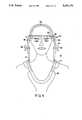
- FIG. 1is a front view of a first embodiment of the device of the present invention when fitted to a wearer.
- FIG. 2is a top view of a first embodiment of the halo of the device of the present invention.
- FIG. 3is a side view of a first embodiment of the device of the present invention when fitted to a wearer.
- FIG. 4is a front view of a first embodiment of the device of the present invention when fitted to a wearer showing placement of skull tongs.
- FIG. 5is a side plan view of a first embodiment of the device of the present invention when fitted to a wearer showing placement of skull tongs.
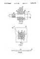
- FIG. 6is a cross-sectional view of a skull pin and accompanying vibrational isolator of the present invention, taken along line 6--6 of FIG. 7.
- FIG. 7is a cross-sectional view of a skull pin and accompanying vibrational isolator of the present invention.
- FIG. 8is a side view of a vertical height adjuster of a first embodiment of the device of the present invention.
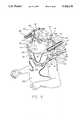
- FIG. 9is a perspective view of a second embodiment of the device of the present invention when fitted to a wearer.
- FIG. 10is a perspective view of a second embodiment of the device of the present invention.
- FIG. 11is a side view of a second embodiment of the device of the present invention when fitted to a wearer.
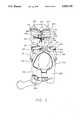
- FIG. 12is a perspective view of a second embodiment of the halo of the present invention.
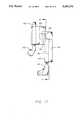
- FIG. 13is a partial cross-sectional view of the vertical and lateral height adjuster of a second embodiment of the device of the present invention.
- FIG. 14is a partial cross-sectional view of the vertical and lateral height adjuster of a second embodiment of the device of the present invention.
- FIG. 15is a partial cross-sectional view of the vertical and lateral height adjuster of a second embodiment of the device of the present invention.
- FIG. 16is a partial side view of the superstructure of the device of the present invention.
- FIG. 17is a partial side view of the superstructure of the device of the present invention with the extension reversed.
- head immobilizing device 10comprises generally halo, or elliptical member, 20, and means for rigidly attaching the halo to the patient's body, comprising generally a vest 12 and a superstructure 14. It should be noted that the left and right sides of superstructure 14 are mirror images of one another. This is also true for superstructure 114.
- the component 20 of the present inventionwill be referred to here as a "halo" which is the term commonly used by those skilled in the art, or "elliptical member” which defines the component in terms of its shape. It should be understood that these terms are being used interchangeably.
- Halo 20is a truncated elliptical member as may be seen from FIG. 2.
- the haloWhen applied to a patient, as shown in FIG. 3, the halo encircles the patient's head horizontally, just above the ears and eyebrows of the patient. This area may be referred to as the "equator" of the patient's head, or as a capital-distal plane.
- the halois truncated, so the back thereof is removed and open.
- the "back" or "front” of the halorefer to the portions of the halo at the posterior and anterior of the patient respectively when the halo is applied as shown in FIG. 3.
- the truncationallows the halo to be applied to a person secured to a backboard or lying supine in a bed, without removal of the patient's head from the backboard or bed surface.
- Adjacent the truncated section of the haloare two downwardly projecting segments 21, which extend out of the plane of the major portion of the halo. The extension of these sections allows one to obtain a more secure grip on the head of the patient by placing the skull pins below the capital-distal plane where optimum bone purchase is achieved.
- a halo in which these segments 21 were not extendedcould also be used, but the halo with segments 21 extended downwardly is preferred.
- halo 20also includes a stiffening brim 22 integrally associated therewith.
- the brimis generally a flat, arcuate piece of material and may be made from the same material of construction as the remainder of the curved halo 20.
- Brim 22may be made separately from the remainder of halo 20, in which case the brim should be welded, or permanently attached by other means to halo 20. If made separately, brim 22 can be made from a different material from halo 20. Brim 22 may also be made integrally with the remainder of halo 20 as a one-piece, molded or formed unit.
- the brimadds rigidity and flexural stability to halo 20, and this allows the integrity of the ring to be broken and the skull pins to be securely fastened to the patient's head without movement or flexing of halo 20, which would otherwise cause the skull pins to move, leading to infection and associated problems.
- Brim 22is located in the front of halo 20, but may also extend over the entire length of halo 20 as shown in FIG. 5.
- halo 120has no brim and no downwardly projecting segments adjacent the truncated end, unlike the first embodiment halo 20.
- the halo 120is constructed by compression molding of a rigid polymer matrix with embedded graphite fibers. This produces a lightweight rigid halo which has very low with electromagnetic imaging techniques.
- Halo 20is provided with a plurality of holes 23 which allow for the use of skull pins 24.
- the manner for attaching skull pins 24 to halo 20may be more clearly seen from FIG. 6.
- Alternative embodiment halo 120also includes holes 123 for securing skull pins 24 as shown in FIGS. 9-12.
- skull pins 24which are generally formed from a non-magnetic alloy such as a titanium alloy. Such vibrations may cause loosening of skull pins 24. This leads to movement of the skull pins on the patient's head. This can cause the patient's skull to wear down in those places where the skull pins are located. Then, even after tightening, skull pins 24 cannot grip the patient's head securely. Further, movement of skull pins 24 can lead to infection where the pins enter the patient's skin.
- FIG. 6shows skull pin 24 which screws into molded nut 26 thru threads 27. Molded nut 26 is held in rubber isolation mount 29 which, in turn, is fitted in one of the mounting holes 23. Molded nut 26 has a key 28 to prevent rotation of nut 26 with respect to isolation mount 29. Isolation mount 29 also includes keys 43 to prevent rotation with respect to halos 20 and 120. Isolation mount 29 may be made from any suitable elastomeric material and is preferably made from hard rubber which has a high durometer.
- Molded nut 26, fiber washer 32, and nut 33may all be made from the same material, such as a polymeric resin, a carbon or glass fiber reinforced resin, or a non-magnetic metal alloy.
- a long glass fiber reinforced nylon compositesuch as Verton from LNP Engineering Plastics in Exton, Pa. may be used for halo 20.
- molded nut 26, fiber washer 32, and nut 33should not be made from a magnetic material so that the patient can be subjected to magnetic resonance imaging or similar diagnostic procedures.
- a polyether sulfonealso from LNP Engineering Plastics in Exton, Pa. is recommended. These considerations also apply to halo 120. As previously explained, a compression molded graphite reinforced composite is thus preferred for the construction of halo 120.
- the entire vibration isolation assemblycomprising molded nut 26, rubber isolation mount 29, fiber washer 32, and nut 33, is held in halo 20 through mounting hole 23 and serves to hold halo 20 rigidly to the patient's head while preventing transmission of vibrations from the patient's vest, superstructure, and halo, to skull pins 24. Skull pins 24 are therefore less likely to loosen or move, and associated complications are reduced. Furthermore, this vibrational isolation assembly can be used throughout the superstructure.
- halos 20 and 120also includes depressed segments 25 and 125 respectively on either side of the halos, located approximately midway between the front of the halo where the brim is located on halo 20 and the back of the halo which has been truncated.
- the depressed segments 25provide a number of advantages. As may be seen from FIGS. 4 and 5, depressed segments 25 and 125 allow skull tongs 30 to remain in position on the patient's head while halo 20 is applied. Generally, skull tongs are used for applying traction to a patient in the supine position. The skull tongs are generally applied on the equatorial (or capital distal) plane of the patient's head.
- Depressed segments 25 and 125allow for attachment of skull tongs 30 while halo 20 or 120 is secured to the patient, or alternatively, allows halo 20 or 120 to be positioned while skull tongs 30 remain in place.
- the open back of halo 20 or 120enables the halo to be manipulated around skull tongs 30 or a cable attached thereto for supplying traction. The patient can therefore be subjected to traction without a vest while the halo is in place.
- Skull tongs 30can be secured directly to halo 20, as may be seen in FIG. 5.
- Halo 120also provides for attachment of skull tongs 30. Skull tongs 30 are equipped with flanges 34.
- the flangesattach to the skull tongs 30 and to holes 35 in halo 20 and holes 104 in halo 120. These holes may be threaded to accommodate a fastener or a nut may be used with the fastener.
- Depressed segment 25allows proper placement of the skull tongs 30 with skull pin 24 in the equatorial plane of the patient's head.
- Depressed segments 25also provide for attachment of halo 20 to supporting superstructure 14 as shown in FIGS. 3-5.
- Halo 20attaches to vertical height adjuster 37 through lock screw 36.
- Vertical height adjusteris in turn secured to vertical support 39.
- Vertical height adjuster 37 and vertical support 39are equipped with V-grooves 46 and 49 respectively.
- Vertical height adjuster 37 and vertical support 39are arranged such that the V-grooves interlock and thus hold the halo securely.
- Vertical height adjuster 37can be more easily seen in FIG. 8.
- V-grooves 46are adapted to interlock with V-grooves 49 on vertical support 39.
- Vertical height adjuster 37also has V-grooves which interlock with V-grooves on halo 20. These V-grooves grooves on vertical height adjuster 37 and halo 20 cannot be seen from the Figures since superstructure 14 is shown assembled mounted on a patient.
- Vertical support 39is attached to over shoulder bar 41, by means of flange 44 on over shoulder bar 41.
- Vertical support 39 and flange 44each have V-grooves which interlock. By loosening lock screw 45 rotation about the screw is possible to obtain rotational adjustment of the halo 20.
- over the shoulder barsare hinged at ball and socket joint 55 to allow rotation around the patient, so that they may be applied while a patient is supine in bed.
- Lock knob 38is knurled and can be hand tightened and adjusted to facilitate adjustment of the height of superstructure 14 and halo 20.
- Lock knob 38also includes an allen-type (hex socket) locking screw for locking the knob when suitable adjustments have been made. All parts of superstructure 14 are preferably made from the same or similar material to that used for halo 20 since superstructure should also be nonmagnetic and should not allow artifact during diagnostic imaging.
- Lateral adjustment of halo 20 and superstructure 14may be made by means of lateral lock nut 52, as shown in FIGS. 1, 3, and 5.
- Chest bar 50connects the two sides of superstructure 14 and front brace 51 connects thereto.
- Front brace 51comprises the front portion of over shoulder bar 41.
- Front brace 51has V-grooves where it connects to chest bar 50. This allows simple adjustment and securing of the superstructure.
- halo 120is very similar to halo 20 in many ways. Every consideration taken into account in making halo 20 was incorporated into halo 120, excepting brim 22, and therefore all skull pins, skull tongs, vibrational isolators, and keys will also fit halo 120. The only other difference between halo 20 and halo 120 is that halo 120 has been expanded slightly in the region of depressed segments 125 in order to allow more room to accommodate the ears of the patient.
- halo 120is very similar to halo 20
- superstructure 114is very different from superstructure 14, as may be seen from FIGS. 9-11.
- Superstructure 114holds the head of a patient in a fixed relationship to the body of the patient. Therefore rigid attachment to both the body and head of the patient is necessary.
- Superstructure 114attaches to the body of the patient by means of a vest consisting of front vest portion 112a and rear vest portion 112b. The vest is attached to the patient's body by hook and loop shoulder straps 102 and side buckles 104.
- Superstructure 114is attached to front vest portion 112a and rear vest portion 112b via front brace 105 and rear brace 106 respectively.
- front brace 105To front brace 105 is secured front right upright 116 and front left upright 118 (right and left taken as the patient's right and left).
- rear brace 106To rear brace 106 is secured rear right upright 126 and rear left upright 128.
- Uprights 116, 118, 126, and 128are secured to braces 105 and 106 by any conventional means. Threaded fasteners are preferred since they allow loosening and retightening for adjustment.
- hex cap threaded fasteners 111which are knurled on the outside of the head while receiving an internal hex key are preferred. In this way, one hex key can be used for all fasteners and adjustments herein.
- Uprights 116 and 118are in turn secured to front right top 122 and front left top 124 respectively through ball and socket joints 130 (where the ball and socket are attached to the upright and top respectively). Uprights 126 and 128 are similarly secured to rear right top 132 and rear left top 134 respectively Ball and socket joint 120 may also include an o-ring situated within the joint to prevent transmission of vibrations from vest portions 112a and 112b to superstructure 114.
- Front tops 122 and 124include right and left female pieces 125 and 127 respectively, each having a collet 129 thereon.
- Right and left female pieces 125 and 127accept right and left male pieces 135 and 137 respectively.
- Male pieces 135 and 137slide in and out of female pieces 125 and 127 and can be locked in place by collets 129. The allows for the continuously variable adjustment of the front to back thickness of the superstructure 114.
- Vertical pieces 140Secured to front tops 122 and 124 are vertical pieces 140.
- Vertical pieces 140are secured with threaded hex cap fasteners 111.
- Vertical pieces 140can be more easily seen in FIGS. 13, 14, and 15.
- Vertical piece 140includes rack 142 running vertically along the inside of a channel 144 cut through vertical piece 140.
- Vertical piece 140fits into a channel 146 in a T-bar 148.
- T-bar 148has a horizontal section 147 and a vertical stem 149.
- T-bar 148also includes pinion gear 150 which mates with rack 142.
- Pinion gear 150has a hexagonal opening in the center thereof of the same size as the hexagonal openings in threaded hex cap fasteners 111.
- a threaded hex cap fastenerfunctions as a set screw 152.
- Set screw 152engages between T-bar cover 156 and T-bar 148.
- the key for the fastenercan be inserted into pinion gear 150 and turned. This rotation of pinion gear 150 provides continuous adjustment of T-bar 148 with respect to vertical piece 140. This adjusts the height of superstructure 114.
- T-bar 148has two racks 154. These racks interact with gears 158 on connector 160. Rotation of gears 158 provides anterior to posterior adjustability of connector 160 with respect to T-bar 148. This in turn provides anterior to posterior adjustability of halo 120 with respect to vest portions 112a and 112b and thus with respect to the body of the patient.
- Connector 160also includes hex cap set screw 162 which extends through channel 164 in T-bar 148 and which can be tightened once the correct anterior to posterior position of halo 120 has been achieved.
- extension 170is secured to connect 160.
- Extension 170includes a channel 172 therethrough and a rack 174 contained within channel 172.
- Connect 160includes pinion gear 167 and hex cap set screws 169 which provide movement and locking of extension 170 with respect to connect 160 respectively.
- Extension 170also includes a ball 176 to which halo 120 can be indirectly attached.
- extension 170can be removed and reversed (turned upside down) as shown in FIG. 17. This is necessary to make certain that with the adjustability of T-bar 148 and extension 170, all possible positions of ball 176 can be accessed.
- socket 180 and spacer 182are secured with a hex cap set screw 184, which passes through socket 180 and spacer 182 and into halo 120.
- Spacer 182is optional, and is used when the halo appropriate for the head of the patient is slightly smaller than the width of the right and left portions of superstructure 114.
- Hex cap set screw 184is located in cavity 186 in ball 176. Cavity 186 is rounded on the inside to allow for free movement of set screw 184.
Landscapes
- Health & Medical Sciences (AREA)
- Nursing (AREA)
- Orthopedic Medicine & Surgery (AREA)
- Engineering & Computer Science (AREA)
- Biomedical Technology (AREA)
- Heart & Thoracic Surgery (AREA)
- Vascular Medicine (AREA)
- Life Sciences & Earth Sciences (AREA)
- Animal Behavior & Ethology (AREA)
- General Health & Medical Sciences (AREA)
- Public Health (AREA)
- Veterinary Medicine (AREA)
- Apparatus For Radiation Diagnosis (AREA)
Abstract
Description
Claims (15)
Priority Applications (1)
| Application Number | Priority Date | Filing Date | Title |
|---|---|---|---|
| US07/963,442US5302170A (en) | 1991-01-04 | 1992-10-19 | External fixation system for the neck |
Applications Claiming Priority (2)
| Application Number | Priority Date | Filing Date | Title |
|---|---|---|---|
| US07/647,228US5156588A (en) | 1991-01-04 | 1991-01-04 | External fixation system for the neck |
| US07/963,442US5302170A (en) | 1991-01-04 | 1992-10-19 | External fixation system for the neck |
Related Parent Applications (1)
| Application Number | Title | Priority Date | Filing Date |
|---|---|---|---|
| US07/647,228Continuation-In-PartUS5156588A (en) | 1991-01-04 | 1991-01-04 | External fixation system for the neck |
Publications (1)
| Publication Number | Publication Date |
|---|---|
| US5302170Atrue US5302170A (en) | 1994-04-12 |
Family
ID=46246895
Family Applications (1)
| Application Number | Title | Priority Date | Filing Date |
|---|---|---|---|
| US07/963,442Expired - LifetimeUS5302170A (en) | 1991-01-04 | 1992-10-19 | External fixation system for the neck |
Country Status (1)
| Country | Link |
|---|---|
| US (1) | US5302170A (en) |
Cited By (43)
| Publication number | Priority date | Publication date | Assignee | Title |
|---|---|---|---|---|
| US5456266A (en)* | 1993-12-01 | 1995-10-10 | Brown; Cameron C. | Cranial traction tong convertible to a halo and a method of applying a halo to a patient |
| US5674186A (en)* | 1995-03-09 | 1997-10-07 | Etablissements Proteor | Halo consisting of positionally adjustable elements and capable of being fixed in a plurality of adjustable positions on the cranium of a patient |
| US5832926A (en)* | 1995-12-27 | 1998-11-10 | Towlen; Paul Raymond | Head support device |
| US5865780A (en)* | 1995-10-13 | 1999-02-02 | Sdgi Holdings, Inc. | Transportable cervical immobilization device |
| FR2768332A1 (en)* | 1997-09-18 | 1999-03-19 | Berrehail Mohammed | Limb immobilization and support apparatus |
| US5916189A (en)* | 1997-12-19 | 1999-06-29 | Ge Yokogawa Medical Systems, Limited | Neck fixing apparatus |
| US5961528A (en)* | 1997-12-10 | 1999-10-05 | Depuy Ace Medical Company | Insulated skull pins |
| WO2002069827A1 (en)* | 2001-03-02 | 2002-09-12 | Steven Streatfield Gill | Patient frame constructed from composite material |
| US6500136B2 (en) | 1999-02-18 | 2002-12-31 | Donald W. Meyer | Cervical remodeling collar |
| US6663630B2 (en) | 2001-09-07 | 2003-12-16 | Spine Works Llc | Halo/collar cervical orthosis |
| US20050154339A1 (en)* | 2004-01-13 | 2005-07-14 | Farley Daniel K. | Cervical orthosis |
| US20050245854A1 (en)* | 2004-04-21 | 2005-11-03 | Washington University | Cervical brace |
| US20060135897A1 (en)* | 2004-12-21 | 2006-06-22 | Dellanno Ronald P | Forward head posture correction collar |
| US20070106194A1 (en)* | 2005-11-07 | 2007-05-10 | The Jerome Group | Traction collar and method of use |
| US20080251086A1 (en)* | 2007-04-13 | 2008-10-16 | Dinkler Charles E | Limited artifact skull pin |
| US20090149788A1 (en)* | 2004-12-21 | 2009-06-11 | Dellanno Ronald P | Forward head posture correction collar |
| US20090187129A1 (en)* | 2008-01-22 | 2009-07-23 | Peleg Ben-Galim | Trauma cervical stability device and methods of using same for diagnostic purposes |
| US20090264938A1 (en)* | 2008-03-12 | 2009-10-22 | Eric Bailey | Composite skull pins with reduced x-ray signature |
| USD616555S1 (en) | 2009-09-14 | 2010-05-25 | Ossur Hf | Orthopedic device |
| USD616997S1 (en) | 2009-09-14 | 2010-06-01 | Ossur Hf | Orthopedic device |
| USD616996S1 (en) | 2009-09-14 | 2010-06-01 | Ossur Hf | Orthopedic device |
| US20100137768A1 (en)* | 2008-12-03 | 2010-06-03 | Thora Thorgilsdottir | Cervical collar having height and circumferential adjustment |
| US20100217280A1 (en)* | 2009-02-26 | 2010-08-26 | Schuele Matthias E | Method and Apparatus for a Radiolucent and MRI Compatible Cranial Stabilization Pin |
| US20100286581A1 (en)* | 2008-01-22 | 2010-11-11 | Hipp John A | Trauma cervical stability device and methods of using same for diagnostic purposes |
| US20110034844A1 (en)* | 2009-08-10 | 2011-02-10 | Thora Thorgilsdottir | Cervical collar having height and circumferential adjustment |
| USD633214S1 (en)* | 2008-12-02 | 2011-02-22 | Camp Scandinavia Ab | Hyperextension brace |
| US20110066094A1 (en)* | 2008-12-03 | 2011-03-17 | Thora Thorgilsdottir | Cervical collar with reduced vascular obstruction |
| USD647623S1 (en) | 2010-08-06 | 2011-10-25 | Ossur Hf | Height adjustment mechanism for cervical collar |
| USD647624S1 (en) | 2010-08-06 | 2011-10-25 | Ossur Hf | Cervical collar |
| US9011357B2 (en) | 2011-09-06 | 2015-04-21 | Deroyal Industries, Inc. | Cervical collar with cable adjustment system |
| CN105997322A (en)* | 2016-05-06 | 2016-10-12 | 西安市红会医院 | Cervical vertebra three-dimensional controllable head loop waistcoat drawing reset device and use method thereof |
| US9713546B2 (en) | 2012-05-21 | 2017-07-25 | Ossur Hf | Cervical collar |
| US9833289B2 (en) | 2009-02-26 | 2017-12-05 | pro med instruments, GmbH | Method and apparatus for a radiolucent and MRI compatible cranial stabilization pin |
| US9943433B2 (en) | 2011-09-06 | 2018-04-17 | Deroyal Industries, Inc. | Cervical collar with cable adjustment system |
| US20190046347A1 (en)* | 2017-08-11 | 2019-02-14 | Giacinto CONGIU | System for immobilizing the head and the cervical region of a patient |
| USD866773S1 (en) | 2017-09-06 | 2019-11-12 | Ossur Iceland Ehf | Cervical collar |
| USD870899S1 (en) | 2017-09-06 | 2019-12-24 | Ossur Iceland Ehf | Cervical collar |
| US10512559B2 (en) | 2016-02-25 | 2019-12-24 | Ossur Iceland Ehf | Cervical collar having height adjustment |
| US10842653B2 (en) | 2007-09-19 | 2020-11-24 | Ability Dynamics, Llc | Vacuum system for a prosthetic foot |
| US10945872B2 (en) | 2016-09-19 | 2021-03-16 | Ossur Iceland Ehf | Cervical collar |
| CN112656492A (en)* | 2020-11-17 | 2021-04-16 | 温州医科大学附属第二医院、温州医科大学附属育英儿童医院 | Head ring vest |
| US11083616B2 (en) | 2015-04-06 | 2021-08-10 | Ossur Iceland Ehf | Cervical collar having height adjustment |
| US11357656B2 (en)* | 2016-11-25 | 2022-06-14 | Orion Biotech Inc. | Halo vests and construction methods thereof |
Citations (28)
| Publication number | Priority date | Publication date | Assignee | Title |
|---|---|---|---|---|
| US2225274A (en)* | 1937-05-27 | 1940-12-17 | Macgoun Maxwell Duncan | Ganthostat |
| US2820455A (en)* | 1953-12-28 | 1958-01-21 | Newton J Hall | Neck brace |
| US2855202A (en)* | 1957-07-08 | 1958-10-07 | Marvin A Kinne | Neck exercising device |
| SU140162A1 (en)* | 1960-12-12 | 1961-11-30 | В.Е. Брык | Device for dosed stretching of the cervical vertebrae |
| US3072118A (en)* | 1957-12-26 | 1963-01-08 | Reginald G Standerwick | Fracture appliance |
| US3604412A (en)* | 1968-09-16 | 1971-09-14 | William J Gardner | Therapeutic device |
| US3654923A (en)* | 1970-04-08 | 1972-04-11 | William Gayle Crutchfield | Skull tongs |
| US3669102A (en)* | 1969-06-09 | 1972-06-13 | Norman M Harris | Orthopedic traction apparatus |
| US3923046A (en)* | 1973-02-22 | 1975-12-02 | Milton D Heifetz | Skull tong |
| US4112935A (en)* | 1976-11-03 | 1978-09-12 | Anvar Latypovich Latypov | Apparatus for surgical treatment of scoliosis |
| SU633526A1 (en)* | 1976-08-11 | 1978-11-25 | Karskanov Vladimir K | Device for extending vertebral column beyond cranial bones |
| US4267830A (en)* | 1979-01-25 | 1981-05-19 | Vick Wiley D | Combination spine board and head stabilizer |
| US4360028A (en)* | 1980-01-14 | 1982-11-23 | Barbier Jean Y | Cranial insertion of surgical needle utilizing computer-assisted tomography |
| US4397307A (en)* | 1979-09-13 | 1983-08-09 | Waldemar Link Gmbh & Co. | Cranial extension holder |
| US4444179A (en)* | 1981-03-02 | 1984-04-24 | Trippi Anthony C | Orthopedic tongs |
| DE3302078A1 (en)* | 1983-01-22 | 1984-07-26 | Orthomed Chirurgische Instrumente GmbH, 6147 Lautertal | Spinal appliance |
| US4541421A (en)* | 1984-04-03 | 1985-09-17 | Pmt, Inc. | Halo fixation system |
| US4612930A (en)* | 1985-03-19 | 1986-09-23 | Bremer Paul W | Head fixation apparatus including crown and skull pin |
| US4644943A (en)* | 1984-07-20 | 1987-02-24 | Regents Of The University Of Minnesota | Bone fixation device |
| US4667660A (en)* | 1985-02-19 | 1987-05-26 | Ace Medical Company | Universal orthopedic traction tongs assembly |
| US4735196A (en)* | 1986-11-10 | 1988-04-05 | Krag Martin H | Cervical-thoracic orthosis and method |
| SU1489760A1 (en)* | 1987-11-16 | 1989-06-30 | Romualdas V Savitskas | Head holder for extending spinal column |
| SU1503797A1 (en)* | 1987-12-23 | 1989-08-30 | В. В. Валкадов | Distraction-reposition apparatus |
| US4913135A (en)* | 1986-12-16 | 1990-04-03 | Mattingly Leslie G | Cervical brace |
| US5010881A (en)* | 1988-07-27 | 1991-04-30 | Kirschner Medical Corporation | Orthopedic fixation device |
| US5062415A (en)* | 1990-09-17 | 1991-11-05 | Sttop Industries, Inc. | Cervical traction orthotic device |
| US5063920A (en)* | 1990-09-11 | 1991-11-12 | Moore W Philip | Halo fixation device and method of use |
| US5088482A (en)* | 1990-12-11 | 1992-02-18 | Mcguinness Charles | Cervical brace |
- 1992
- 1992-10-19USUS07/963,442patent/US5302170A/ennot_activeExpired - Lifetime
Patent Citations (28)
| Publication number | Priority date | Publication date | Assignee | Title |
|---|---|---|---|---|
| US2225274A (en)* | 1937-05-27 | 1940-12-17 | Macgoun Maxwell Duncan | Ganthostat |
| US2820455A (en)* | 1953-12-28 | 1958-01-21 | Newton J Hall | Neck brace |
| US2855202A (en)* | 1957-07-08 | 1958-10-07 | Marvin A Kinne | Neck exercising device |
| US3072118A (en)* | 1957-12-26 | 1963-01-08 | Reginald G Standerwick | Fracture appliance |
| SU140162A1 (en)* | 1960-12-12 | 1961-11-30 | В.Е. Брык | Device for dosed stretching of the cervical vertebrae |
| US3604412A (en)* | 1968-09-16 | 1971-09-14 | William J Gardner | Therapeutic device |
| US3669102A (en)* | 1969-06-09 | 1972-06-13 | Norman M Harris | Orthopedic traction apparatus |
| US3654923A (en)* | 1970-04-08 | 1972-04-11 | William Gayle Crutchfield | Skull tongs |
| US3923046A (en)* | 1973-02-22 | 1975-12-02 | Milton D Heifetz | Skull tong |
| SU633526A1 (en)* | 1976-08-11 | 1978-11-25 | Karskanov Vladimir K | Device for extending vertebral column beyond cranial bones |
| US4112935A (en)* | 1976-11-03 | 1978-09-12 | Anvar Latypovich Latypov | Apparatus for surgical treatment of scoliosis |
| US4267830A (en)* | 1979-01-25 | 1981-05-19 | Vick Wiley D | Combination spine board and head stabilizer |
| US4397307A (en)* | 1979-09-13 | 1983-08-09 | Waldemar Link Gmbh & Co. | Cranial extension holder |
| US4360028A (en)* | 1980-01-14 | 1982-11-23 | Barbier Jean Y | Cranial insertion of surgical needle utilizing computer-assisted tomography |
| US4444179A (en)* | 1981-03-02 | 1984-04-24 | Trippi Anthony C | Orthopedic tongs |
| DE3302078A1 (en)* | 1983-01-22 | 1984-07-26 | Orthomed Chirurgische Instrumente GmbH, 6147 Lautertal | Spinal appliance |
| US4541421A (en)* | 1984-04-03 | 1985-09-17 | Pmt, Inc. | Halo fixation system |
| US4644943A (en)* | 1984-07-20 | 1987-02-24 | Regents Of The University Of Minnesota | Bone fixation device |
| US4667660A (en)* | 1985-02-19 | 1987-05-26 | Ace Medical Company | Universal orthopedic traction tongs assembly |
| US4612930A (en)* | 1985-03-19 | 1986-09-23 | Bremer Paul W | Head fixation apparatus including crown and skull pin |
| US4735196A (en)* | 1986-11-10 | 1988-04-05 | Krag Martin H | Cervical-thoracic orthosis and method |
| US4913135A (en)* | 1986-12-16 | 1990-04-03 | Mattingly Leslie G | Cervical brace |
| SU1489760A1 (en)* | 1987-11-16 | 1989-06-30 | Romualdas V Savitskas | Head holder for extending spinal column |
| SU1503797A1 (en)* | 1987-12-23 | 1989-08-30 | В. В. Валкадов | Distraction-reposition apparatus |
| US5010881A (en)* | 1988-07-27 | 1991-04-30 | Kirschner Medical Corporation | Orthopedic fixation device |
| US5063920A (en)* | 1990-09-11 | 1991-11-12 | Moore W Philip | Halo fixation device and method of use |
| US5062415A (en)* | 1990-09-17 | 1991-11-05 | Sttop Industries, Inc. | Cervical traction orthotic device |
| US5088482A (en)* | 1990-12-11 | 1992-02-18 | Mcguinness Charles | Cervical brace |
Non-Patent Citations (9)
| Title |
|---|
| Ace Medical Company Advertisements Eact date unknown, Believed to be prior to Jan 4, 1991.* |
| Ace Orthopedia Company Advertisement, Jun. 1973.* |
| Bremer Orthopedics Advertisements Exact date unknown, Believed to be prior to Jan. 4, 1991.* |
| Durr Fillauer Medical, Inc. Advertisements Exact date unknown, Believed to be prior to Jan. 4, 1991.* |
| Durr-Fillauer Medical, Inc. Advertisements Exact date unknown, Believed to be prior to Jan. 4, 1991. |
| Kirschner Orthopedic Appliances Advertisements Exact date unknown, Believed to be prior to Jan. 4, 1991.* |
| Levtech Promotion Materials, 1986.* |
| Progress Mankind Technology (PMT) Corporation Advertisements from 1986 1988.* |
| Progress Mankind Technology (PMT) Corporation Advertisements from 1986-1988. |
Cited By (74)
| Publication number | Priority date | Publication date | Assignee | Title |
|---|---|---|---|---|
| US5490832A (en)* | 1993-12-01 | 1996-02-13 | Brown; Cameron C. | Cranial traction tong convertible to a halo and a method of applying a halo to a patient |
| US5456266A (en)* | 1993-12-01 | 1995-10-10 | Brown; Cameron C. | Cranial traction tong convertible to a halo and a method of applying a halo to a patient |
| US5674186A (en)* | 1995-03-09 | 1997-10-07 | Etablissements Proteor | Halo consisting of positionally adjustable elements and capable of being fixed in a plurality of adjustable positions on the cranium of a patient |
| US5865780A (en)* | 1995-10-13 | 1999-02-02 | Sdgi Holdings, Inc. | Transportable cervical immobilization device |
| US5832926A (en)* | 1995-12-27 | 1998-11-10 | Towlen; Paul Raymond | Head support device |
| FR2768332A1 (en)* | 1997-09-18 | 1999-03-19 | Berrehail Mohammed | Limb immobilization and support apparatus |
| US5961528A (en)* | 1997-12-10 | 1999-10-05 | Depuy Ace Medical Company | Insulated skull pins |
| US6379362B1 (en) | 1997-12-10 | 2002-04-30 | Depuy Acromed, Inc. | Insulated skull pins |
| US5916189A (en)* | 1997-12-19 | 1999-06-29 | Ge Yokogawa Medical Systems, Limited | Neck fixing apparatus |
| US6500136B2 (en) | 1999-02-18 | 2002-12-31 | Donald W. Meyer | Cervical remodeling collar |
| CN1292718C (en)* | 2001-03-02 | 2007-01-03 | 埃莱克塔Ab公司 | Patient frames made of composite materials |
| GB2372706B (en)* | 2001-03-02 | 2005-08-17 | Steven Streatfield Gill | Frame |
| WO2002069827A1 (en)* | 2001-03-02 | 2002-09-12 | Steven Streatfield Gill | Patient frame constructed from composite material |
| US6663630B2 (en) | 2001-09-07 | 2003-12-16 | Spine Works Llc | Halo/collar cervical orthosis |
| US20050154339A1 (en)* | 2004-01-13 | 2005-07-14 | Farley Daniel K. | Cervical orthosis |
| US20050245854A1 (en)* | 2004-04-21 | 2005-11-03 | Washington University | Cervical brace |
| US20090149788A1 (en)* | 2004-12-21 | 2009-06-11 | Dellanno Ronald P | Forward head posture correction collar |
| US20060135897A1 (en)* | 2004-12-21 | 2006-06-22 | Dellanno Ronald P | Forward head posture correction collar |
| US8038635B2 (en)* | 2004-12-21 | 2011-10-18 | Ronald P. Dellanno | Forward head posture correction collar |
| CN101325929B (en)* | 2005-11-07 | 2011-04-20 | 奥索集团公司 | Traction collar and method of use |
| US7449005B2 (en) | 2005-11-07 | 2008-11-11 | Ossur Hf. | Traction collar and method of use |
| WO2007056057A3 (en)* | 2005-11-07 | 2007-09-27 | Jerome Group Inc | Traction collar and method of use |
| US20070106194A1 (en)* | 2005-11-07 | 2007-05-10 | The Jerome Group | Traction collar and method of use |
| US20080251086A1 (en)* | 2007-04-13 | 2008-10-16 | Dinkler Charles E | Limited artifact skull pin |
| US8939976B2 (en)* | 2007-04-13 | 2015-01-27 | II Charles E. Dinkler | Limited artifact skull pin |
| US10842653B2 (en) | 2007-09-19 | 2020-11-24 | Ability Dynamics, Llc | Vacuum system for a prosthetic foot |
| US20090187129A1 (en)* | 2008-01-22 | 2009-07-23 | Peleg Ben-Galim | Trauma cervical stability device and methods of using same for diagnostic purposes |
| US8057415B2 (en) | 2008-01-22 | 2011-11-15 | Baylor College Of Medicine | Trauma cervical stability device and methods of using same for diagnostic purposes |
| US20100286581A1 (en)* | 2008-01-22 | 2010-11-11 | Hipp John A | Trauma cervical stability device and methods of using same for diagnostic purposes |
| US20090264938A1 (en)* | 2008-03-12 | 2009-10-22 | Eric Bailey | Composite skull pins with reduced x-ray signature |
| US8623029B2 (en) | 2008-03-12 | 2014-01-07 | Neurologica Corp. | Composite skull pins with reduced X-ray signature |
| USD633214S1 (en)* | 2008-12-02 | 2011-02-22 | Camp Scandinavia Ab | Hyperextension brace |
| US20110224591A1 (en)* | 2008-12-03 | 2011-09-15 | Thora Thorgilsdottir | Cervical collar having height and circumferential adjustment |
| US10792180B2 (en) | 2008-12-03 | 2020-10-06 | Ossur Hf | Cervical collar |
| US7981068B2 (en) | 2008-12-03 | 2011-07-19 | Ossur Hf | Cervical collar having height and circumferential adjustment |
| US9668906B2 (en) | 2008-12-03 | 2017-06-06 | Ossur Hf | Cervical collar |
| US8870800B2 (en) | 2008-12-03 | 2014-10-28 | össur hf | Cervical collar |
| US8038636B2 (en) | 2008-12-03 | 2011-10-18 | Ossur Hf | Cervical collar having height and circumferential adjustment |
| US20110066094A1 (en)* | 2008-12-03 | 2011-03-17 | Thora Thorgilsdottir | Cervical collar with reduced vascular obstruction |
| US8858481B2 (en) | 2008-12-03 | 2014-10-14 | Ossur Hf | Cervical collar with reduced vascular obstruction |
| US20100137768A1 (en)* | 2008-12-03 | 2010-06-03 | Thora Thorgilsdottir | Cervical collar having height and circumferential adjustment |
| US8679044B2 (en) | 2008-12-03 | 2014-03-25 | Ossur Hf | Cervical collar with reduced vascular obstruction |
| US20100217280A1 (en)* | 2009-02-26 | 2010-08-26 | Schuele Matthias E | Method and Apparatus for a Radiolucent and MRI Compatible Cranial Stabilization Pin |
| US9833289B2 (en) | 2009-02-26 | 2017-12-05 | pro med instruments, GmbH | Method and apparatus for a radiolucent and MRI compatible cranial stabilization pin |
| US9078679B2 (en) | 2009-02-26 | 2015-07-14 | Pro Med Instruments Gmbh | Method and apparatus for a radiolucent and MRI compatible cranial stabilization pin |
| US10292856B2 (en) | 2009-08-10 | 2019-05-21 | Ossur Hf | Cervical collar having height and circumferential adjustment |
| US11369506B2 (en) | 2009-08-10 | 2022-06-28 | Ossur Hf | Cervical collar having height and circumferential adjustment |
| US20110034844A1 (en)* | 2009-08-10 | 2011-02-10 | Thora Thorgilsdottir | Cervical collar having height and circumferential adjustment |
| US12370072B2 (en) | 2009-08-10 | 2025-07-29 | Ossur Hf | Cervical collar having height and circumferential adjustment |
| USD616997S1 (en) | 2009-09-14 | 2010-06-01 | Ossur Hf | Orthopedic device |
| USD616996S1 (en) | 2009-09-14 | 2010-06-01 | Ossur Hf | Orthopedic device |
| USD616555S1 (en) | 2009-09-14 | 2010-05-25 | Ossur Hf | Orthopedic device |
| USD647624S1 (en) | 2010-08-06 | 2011-10-25 | Ossur Hf | Cervical collar |
| USD647623S1 (en) | 2010-08-06 | 2011-10-25 | Ossur Hf | Height adjustment mechanism for cervical collar |
| US9011357B2 (en) | 2011-09-06 | 2015-04-21 | Deroyal Industries, Inc. | Cervical collar with cable adjustment system |
| US9943433B2 (en) | 2011-09-06 | 2018-04-17 | Deroyal Industries, Inc. | Cervical collar with cable adjustment system |
| US9713546B2 (en) | 2012-05-21 | 2017-07-25 | Ossur Hf | Cervical collar |
| US11622878B2 (en) | 2012-05-21 | 2023-04-11 | Ossur Hf | Cervical collar |
| US10675173B2 (en) | 2012-05-21 | 2020-06-09 | Ossur Hf | Cervical collar |
| US11083616B2 (en) | 2015-04-06 | 2021-08-10 | Ossur Iceland Ehf | Cervical collar having height adjustment |
| US11833071B2 (en) | 2015-04-06 | 2023-12-05 | Ossur Iceland Ehf | Cervical collar having height adjustment |
| US12419772B2 (en) | 2015-04-06 | 2025-09-23 | Ossur Iceland Ehf | Cervical collar having height adjustment |
| US10512559B2 (en) | 2016-02-25 | 2019-12-24 | Ossur Iceland Ehf | Cervical collar having height adjustment |
| US11969375B2 (en) | 2016-02-25 | 2024-04-30 | Ossur Iceland Ehf | Cervical collar having height adjustment |
| US11478374B2 (en) | 2016-02-25 | 2022-10-25 | Ossur Iceland Ehf | Cervical collar having height adjustment |
| CN105997322A (en)* | 2016-05-06 | 2016-10-12 | 西安市红会医院 | Cervical vertebra three-dimensional controllable head loop waistcoat drawing reset device and use method thereof |
| US10945872B2 (en) | 2016-09-19 | 2021-03-16 | Ossur Iceland Ehf | Cervical collar |
| US11452633B2 (en) | 2016-09-19 | 2022-09-27 | Ossur Iceland Ehf | Cervical collar |
| US11357656B2 (en)* | 2016-11-25 | 2022-06-14 | Orion Biotech Inc. | Halo vests and construction methods thereof |
| US20190046347A1 (en)* | 2017-08-11 | 2019-02-14 | Giacinto CONGIU | System for immobilizing the head and the cervical region of a patient |
| USD870899S1 (en) | 2017-09-06 | 2019-12-24 | Ossur Iceland Ehf | Cervical collar |
| USD964575S1 (en) | 2017-09-06 | 2022-09-20 | Ossur Iceland Ehf | Dial |
| USD866773S1 (en) | 2017-09-06 | 2019-11-12 | Ossur Iceland Ehf | Cervical collar |
| CN112656492A (en)* | 2020-11-17 | 2021-04-16 | 温州医科大学附属第二医院、温州医科大学附属育英儿童医院 | Head ring vest |
Similar Documents
| Publication | Publication Date | Title |
|---|---|---|
| US5302170A (en) | External fixation system for the neck | |
| US5156588A (en) | External fixation system for the neck | |
| US4913135A (en) | Cervical brace | |
| US5171296A (en) | Stereotaxic headring fixation system and method | |
| US4807605A (en) | Halo traction brace | |
| US4541421A (en) | Halo fixation system | |
| JP5806938B2 (en) | Spinal immobilization | |
| US5865780A (en) | Transportable cervical immobilization device | |
| CA2608141C (en) | Fixator or splint | |
| US6368295B1 (en) | Non-invasive halo-type cervical brace | |
| US5005563A (en) | Mobile-cervical extension and supporting apparatus | |
| US5645079A (en) | Apparatus for mechanically holding, maneuvering and maintaining a body part of a patient during orthopedic surgery | |
| US4504050A (en) | Head support | |
| US4481941A (en) | Universal hip stabilization device | |
| US7011642B2 (en) | External fixation device for cranialmaxillofacial distraction | |
| CA2645244C (en) | Adjustable restraint for the lower leg and/or foot | |
| US6663630B2 (en) | Halo/collar cervical orthosis | |
| US5350378A (en) | Posterior external pelvic fixator | |
| US10709596B2 (en) | Method and apparatus for restraining a patient's leg during leg surgical and interventional procedures | |
| US4543948A (en) | Apparatus and method for applying rotational pressure to parts of the body | |
| US5002046A (en) | Balanced skeletal traction apparatus | |
| US5490832A (en) | Cranial traction tong convertible to a halo and a method of applying a halo to a patient | |
| US7563237B1 (en) | Cranial correction orthoses | |
| US5063920A (en) | Halo fixation device and method of use | |
| US20240252341A1 (en) | Leg and/or extremity support |
Legal Events
| Date | Code | Title | Description |
|---|---|---|---|
| AS | Assignment | Owner name:JEROME GROUP INC., THE, NEW JERSEY Free format text:ASSIGNMENT OF ASSIGNORS INTEREST.;ASSIGNOR:TWEARDY, LISA ANNE GRAVELL;REEL/FRAME:006357/0555 Effective date:19921208 | |
| STCF | Information on status: patent grant | Free format text:PATENTED CASE | |
| FPAY | Fee payment | Year of fee payment:4 | |
| FEPP | Fee payment procedure | Free format text:PAYOR NUMBER ASSIGNED (ORIGINAL EVENT CODE: ASPN); ENTITY STATUS OF PATENT OWNER: LARGE ENTITY | |
| FPAY | Fee payment | Year of fee payment:8 | |
| AS | Assignment | Owner name:ANTARES CAPITAL CORPROATION, AS AGENT, ILLINOIS Free format text:SECURITY INTEREST;ASSIGNOR:JEROME GROUP, INC., THE;REEL/FRAME:015962/0622 Effective date:20041007 | |
| AS | Assignment | Owner name:THE JEROME GROUP INC., NEW JERSEY Free format text:PATENT RELEASE AND REASSIGNMENT;ASSIGNOR:ANTARES CAPITAL CORPORATION;REEL/FRAME:016408/0699 Effective date:20050810 | |
| AS | Assignment | Owner name:KAUPTHING BANK HF, NEW YORK Free format text:SECURITY AGREEMENT;ASSIGNOR:THE JEROME GROUP INC.;REEL/FRAME:016610/0330 Effective date:20050901 | |
| FEPP | Fee payment procedure | Free format text:PAT HOLDER NO LONGER CLAIMS SMALL ENTITY STATUS, ENTITY STATUS SET TO UNDISCOUNTED (ORIGINAL EVENT CODE: STOL); ENTITY STATUS OF PATENT OWNER: LARGE ENTITY | |
| REFU | Refund | Free format text:REFUND - PAYMENT OF MAINTENANCE FEE, 12TH YR, SMALL ENTITY (ORIGINAL EVENT CODE: R2553); ENTITY STATUS OF PATENT OWNER: LARGE ENTITY | |
| FPAY | Fee payment | Year of fee payment:12 | |
| SULP | Surcharge for late payment | Year of fee payment:11 | |
| AS | Assignment | Owner name:OSSUR HF., ICELAND Free format text:ASSIGNMENT OF ASSIGNORS INTEREST;ASSIGNOR:THE JEROME GROUP, INC.;REEL/FRAME:019265/0622 Effective date:20070503 |