US5301985A - Double point supported locking lever for a hose coupling assembly - Google Patents
Double point supported locking lever for a hose coupling assemblyDownload PDFInfo
- Publication number
- US5301985A US5301985AUS08/026,753US2675393AUS5301985AUS 5301985 AUS5301985 AUS 5301985AUS 2675393 AUS2675393 AUS 2675393AUS 5301985 AUS5301985 AUS 5301985A
- Authority
- US
- United States
- Prior art keywords
- locking
- cam lock
- lug
- hose
- raised
- Prior art date
- Legal status (The legal status is an assumption and is not a legal conclusion. Google has not performed a legal analysis and makes no representation as to the accuracy of the status listed.)
- Expired - Lifetime
Links
- 230000008878couplingEffects0.000titleclaimsabstractdescription33
- 238000010168coupling processMethods0.000titleclaimsabstractdescription33
- 238000005859coupling reactionMethods0.000titleclaimsabstractdescription33
- 230000013011matingEffects0.000claimsabstract2
- 238000007789sealingMethods0.000claims1
- 230000000712assemblyEffects0.000description2
- 238000000429assemblyMethods0.000description2
- 201000009032substance abuseDiseases0.000description2
- 238000010276constructionMethods0.000description1
- 230000002079cooperative effectEffects0.000description1
- 230000000694effectsEffects0.000description1
- 230000003014reinforcing effectEffects0.000description1
Images


Classifications
- F—MECHANICAL ENGINEERING; LIGHTING; HEATING; WEAPONS; BLASTING
- F16—ENGINEERING ELEMENTS AND UNITS; GENERAL MEASURES FOR PRODUCING AND MAINTAINING EFFECTIVE FUNCTIONING OF MACHINES OR INSTALLATIONS; THERMAL INSULATION IN GENERAL
- F16L—PIPES; JOINTS OR FITTINGS FOR PIPES; SUPPORTS FOR PIPES, CABLES OR PROTECTIVE TUBING; MEANS FOR THERMAL INSULATION IN GENERAL
- F16L37/00—Couplings of the quick-acting type
- F16L37/08—Couplings of the quick-acting type in which the connection between abutting or axially overlapping ends is maintained by locking members
- F16L37/10—Couplings of the quick-acting type in which the connection between abutting or axially overlapping ends is maintained by locking members using a rotary external sleeve or ring on one part
- F16L37/113—Couplings of the quick-acting type in which the connection between abutting or axially overlapping ends is maintained by locking members using a rotary external sleeve or ring on one part the male part having lugs on its periphery penetrating into the corresponding slots provided in the female part
- F—MECHANICAL ENGINEERING; LIGHTING; HEATING; WEAPONS; BLASTING
- F16—ENGINEERING ELEMENTS AND UNITS; GENERAL MEASURES FOR PRODUCING AND MAINTAINING EFFECTIVE FUNCTIONING OF MACHINES OR INSTALLATIONS; THERMAL INSULATION IN GENERAL
- F16L—PIPES; JOINTS OR FITTINGS FOR PIPES; SUPPORTS FOR PIPES, CABLES OR PROTECTIVE TUBING; MEANS FOR THERMAL INSULATION IN GENERAL
- F16L37/00—Couplings of the quick-acting type
- F16L37/24—Couplings of the quick-acting type in which the connection is made by inserting one member axially into the other and rotating it to a limited extent, e.g. with bayonet-action
- F16L37/244—Couplings of the quick-acting type in which the connection is made by inserting one member axially into the other and rotating it to a limited extent, e.g. with bayonet-action the coupling being co-axial with the pipe
- F16L37/252—Couplings of the quick-acting type in which the connection is made by inserting one member axially into the other and rotating it to a limited extent, e.g. with bayonet-action the coupling being co-axial with the pipe the male part having lugs on its periphery penetrating into the corresponding slots provided in the female part
Definitions
- Hose coupling assembliesare utilized to couple two ends of a hose, such as a fire hose. These hose couplings must be strong and rugged because they must create and hold a tight seal and must be able to withstand impact and abuses of all types while still maintaining a tight and secure seal. Conventionally, these hose coupling assemblies have been of various designs. But one particular design that has been utilized widely is the so-called non-threaded type. Many non-threaded type hose couplings include a pair of rotating collars where each rotating collar includes an externally actuated locking mechanism.
- One particular design for a latching or locking mechanism for a hose coupling assembly of this typeincludes a pivotally mounted lever-type locking arm that is externally actuated but includes a locking head that projects downwardly through the associated collar to engage and lock against a cam latch or lock.
- This lever-type locking armin past designs has been pivotally mounted on a cantilevered pivot pin and because of that, has been very susceptible to breakage and failure. Since the pivot pin for the latch arm is only supported at one end any substantial impact against the free or unsupported end of the pivot pin may break or fracture the pivot pin and accordingly, this can cause the entire coupling assembly to fail.
- the present inventionentails a non-threaded hose coupling assembly that includes an external lever-type latch arm that is integrally formed with an external lug on a respective rotating collar that forms a part of the hose coupling assembly.
- the hose coupling assembly of the present inventionincludes two freely rotating locking collars that are designed to mate together and close tightly against each other to effectively close or secure the coupling assembly.
- Each rotating collarincludes a series of circumferentially spaced lugs formed around the exterior surface of the collar.
- Each locking collarincludes at least one lug that has a transverse cavity opening formed therein and the lever-type latch for the hose coupling extends through this cavity formed in the lug and a pivot pin is supported at both ends across the lug cavity.
- the latch armcan be rotated about the double point supported pivot pin and the lug itself has the effect of protecting the pin at both ends from substantial impact.
- Still a further object of the present inventionis to provide a non-threaded hose coupling that affords better protection against "snap" breakage.
- Another object of the present inventionresides in the provision of a non-threaded hose coupling assembly that includes one or more lever-type latches that provide for double shear points on the pivot pin supporting the lever-type latch.
- Still a further object of the present inventionresides in the provision of a non-threaded hose coupling assembly wherein the latch of the coupling assembly is integral with a lug that is formed on the outside of the coupling assembly.
- FIG. 1is perspective view showing two ends of a hose having the hose coupling assembly of the present invention connected thereto.
- FIG. 2is a fragmentary plan view of a portion of a hose coupling assembly showing the latching mechanism.
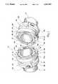
- FIG. 3is a fragmentary cross-sectional view taken through the line 3--3 of FIG. 2.
- FIG. 4is a fragmentary sectional view taken through the line 4--4 of FIG. 2.
- the hose clamping assembly of the present inventionis shown therein and indicated generally by the numeral 10.
- the hose clamping assembly 10is designed to fit about two ends 21 of a hose and to couple the hose together to form a tight and sealed coupled relationship.
- each inner flange 12 and 14includes a face seal 16 and wherein the respective face seals 16 abut each other and form a tight seal connection between the two inner flanges 12 and 14 when the hose coupling assembly 10 assumes a coupled mode.
- each stationing collar 18 and 20is tightly secured down on the exterior of the hose 21 and accordingly forms a tight securement about the hose 21 and effectively sandwiches the hose 21 between a respective inner flange 12 or 14 and a respective stationing collar 18 or 20. It is thusly appreciated that the stationing collars 18 and 20 tightly secure the inner flanges 12 and 14 within the respective hose ends 21.
- a locking collar 22, 24Rotatively mounted between the stationing collars 18 and 20 and the outer sides of the inner flanges 12 and 14 is a locking collar 22, 24.
- Each locking collar 22 and 24is freely rotatable about a respective inner flange 12 and 14.
- the coupling assembly 10will effectively pull the respective locking collars 22 and 24 tightly adjacent the other and will effectively lock the locking collars 22 and 24 in a close and tight coupled relationship.
- the locking collars 22 and 24will in turn pull the face seal 16 of the inner flanges 12 and 14 closely together and form a sealed relationship between the inner flanges 12 and 14.
- each locking collarcomprises an inner sleeve 26 that has a series of reinforcing lugs 28 circumferentially disposed about the outer surface of the inner sleeve 26. Disposed adjacent the inner sleeve 26 and lugs 28 is an outer rim 30. Projecting outwardly from the outer rim 30 on each locking collar 22 and 24 is a pair of spaced apart cam locks 34. As will be appreciated from subsequent portions of the disclosure, the respected cam locks 34 of one locking collar will project therefrom into the other locking collar and by selectively rotating the locking collars 22 and 24 the cam locks will be engaged by locking or latching mechanism so as to securely lock the respective locking collars 22 and 24 together.
- each cam lock 34includes a leading cam edge 34a and a trailing locking edge 34b.
- a cut-out 34cdisposed interiorly of the cam lock 34. The significance of the cut-out 34c will be more fully appreciated from subsequent portions of this disclosure.
- each cam lock stop 42Formed about the outer exposed side of each locking collar 22 and 24 is an outer face 36. Outer face 36 in conjunction with the outer rim 30 forms a race or a recess 38 that extends around the outside of each locking collar 22 and 24. Formed in the outer face 36 is a cam lock inlet 40. The cam lock inlet 40 permits a respective cam lock 34 to be inserted into the recess 38 of the other locking collar 22 or 24. It should be appreciated that the pair of cam locks 34 projecting from a certain locking collar 22 or 24 can be projected into and through the cam lock inlets 40 formed in the other locking collar and thereafter the respective locking collars can be rotated such that the cam locks 34 move through the respective recesses 38 formed around the locking collars 22 and 24. At selected points within each recess 38 there is provided a cam lock stop 42. The purpose of each cam lock stop 42 is to provide a stop that restricts the travel of the respective cam locks 34.
- the respective outer face 36 of the locking-collars 22 and 24are slightly angled or cammed on the inside such that as the cam locks 34 are rotated within the locking collars 22 and 24 during a coupling operation that the respective locking collars 22 and 24 are drawn towards each other. As the locking collars 22 and 24 are drawn towards each other it is appreciated that they engage the adjacent sides of the inner flanges 12 and 14 and accordingly pull the inner flanges 12 and 14 closely together such that the face seals 16 tightly abut each other and form a sealed relationship.
- a latching or locking mechanismindicated generally by the numeral 50 with each locking collar 22 and 24.
- the latching mechanism 50 associated with each locking collar 22 and 24will in a locked mode project downardly through the top of rim 30 and lock against the locking edge 34b of a respective cam lock 34. This will effectively lock a respective cam lock 34 of each locking collar between a stop 42 formed in the recess 38 and the latching mechanism 50 of a respective locking collar.
- each latching mechanism 50is associated with a selected lug 28 formed on the inner sleeve 26 of a respective locking collar 22 or 24.
- a selective lug 28 on each locking collaris formed so as to include a lug cavity or lug cut-out 28a. See FIG. 2 for example. Spanning the lug cut-out 28a is a pivot pin 52. It is appreciated that the pivot pin is supported at both opposed ends as contrasted to being supported in cantilever fashion. Pivotally mounted to the pivot pin 52 is a latching lever arm 54.
- the lever arm 54includes a locking head 56 that in a locked mode extends downwardly through an opening 58 formed in the outer rim 30.
- the latching lever arm 54is biased towards a locked position by a torsional spring 60 wound around the pivot pin 52 and held between the lever arm 54 and the outer rim 30 of a respective collar 22 or 24.
- the cam lock 34 of one locking collaris securely locked in the recess 38 of another locking collar by the cooperative action of the locking head 56 and the adjacent stop 42.
- the lever arm 54is supported on the pivot pin 52 which is in turn supported at spaced and opposed points within the lug cavity of 28a. This permits the locking mechanism 50 to withstand substantial impact and abuse and still maintain the hose coupling assembly 10 in a sealed and locked relationship at all times.
Landscapes
- Engineering & Computer Science (AREA)
- General Engineering & Computer Science (AREA)
- Mechanical Engineering (AREA)
- Quick-Acting Or Multi-Walled Pipe Joints (AREA)
Abstract
Description
Hose coupling assemblies are utilized to couple two ends of a hose, such as a fire hose. These hose couplings must be strong and rugged because they must create and hold a tight seal and must be able to withstand impact and abuses of all types while still maintaining a tight and secure seal. Conventionally, these hose coupling assemblies have been of various designs. But one particular design that has been utilized widely is the so-called non-threaded type. Many non-threaded type hose couplings include a pair of rotating collars where each rotating collar includes an externally actuated locking mechanism. One particular design for a latching or locking mechanism for a hose coupling assembly of this type includes a pivotally mounted lever-type locking arm that is externally actuated but includes a locking head that projects downwardly through the associated collar to engage and lock against a cam latch or lock. This lever-type locking arm in past designs has been pivotally mounted on a cantilevered pivot pin and because of that, has been very susceptible to breakage and failure. Since the pivot pin for the latch arm is only supported at one end any substantial impact against the free or unsupported end of the pivot pin may break or fracture the pivot pin and accordingly, this can cause the entire coupling assembly to fail.
Therefore, there is and continues to be a need for a strong and sturdy external latch assembly for a non-threaded hose coupling assembly.
The present invention entails a non-threaded hose coupling assembly that includes an external lever-type latch arm that is integrally formed with an external lug on a respective rotating collar that forms a part of the hose coupling assembly. In particular, the hose coupling assembly of the present invention includes two freely rotating locking collars that are designed to mate together and close tightly against each other to effectively close or secure the coupling assembly. Each rotating collar includes a series of circumferentially spaced lugs formed around the exterior surface of the collar. Each locking collar includes at least one lug that has a transverse cavity opening formed therein and the lever-type latch for the hose coupling extends through this cavity formed in the lug and a pivot pin is supported at both ends across the lug cavity. Thus, the latch arm can be rotated about the double point supported pivot pin and the lug itself has the effect of protecting the pin at both ends from substantial impact.
It is therefore an object of the present invention to provide an improved support structure for supporting one or more latches that form a part of a non-threaded hose coupling.
Still a further object of the present invention is to provide a non-threaded hose coupling that affords better protection against "snap" breakage.
Another object of the present invention resides in the provision of a non-threaded hose coupling assembly that includes one or more lever-type latches that provide for double shear points on the pivot pin supporting the lever-type latch.
Still a further object of the present invention resides in the provision of a non-threaded hose coupling assembly wherein the latch of the coupling assembly is integral with a lug that is formed on the outside of the coupling assembly.
Other objects and advantages of the present invention will become apparent and obvious from a study of the following description and the accompanying drawings which are merely illustrative of such invention.
FIG. 1 is perspective view showing two ends of a hose having the hose coupling assembly of the present invention connected thereto.
FIG. 2 is a fragmentary plan view of a portion of a hose coupling assembly showing the latching mechanism.
FIG. 3 is a fragmentary cross-sectional view taken through theline 3--3 of FIG. 2.
FIG. 4 is a fragmentary sectional view taken through the line 4--4 of FIG. 2.
With further reference to the drawings, the hose clamping assembly of the present invention is shown therein and indicated generally by thenumeral 10. As seen in the drawings, thehose clamping assembly 10 is designed to fit about twoends 21 of a hose and to couple the hose together to form a tight and sealed coupled relationship.
Viewing thecoupling assembly 10 in more detail, it is seen that the same includes a pair ofinner flanges hose 21 and projecting outwardly therefrom. Eachinner flange face seal 16 and wherein therespective face seals 16 abut each other and form a tight seal connection between the twoinner flanges hose coupling assembly 10 assumes a coupled mode.
To secure theinner flanges hose ends 21, there is provided astationing collar hose end 21. Eachstationing collar hose 21 and accordingly forms a tight securement about thehose 21 and effectively sandwiches thehose 21 between a respectiveinner flange stationing collar stationing collars inner flanges
Rotatively mounted between thestationing collars inner flanges locking collar locking collar inner flange coupling assembly 10 will effectively pull therespective locking collars locking collars locking collars face seal 16 of theinner flanges inner flanges
Now viewing therespective locking collars inner sleeve 26 that has a series of reinforcinglugs 28 circumferentially disposed about the outer surface of theinner sleeve 26. Disposed adjacent theinner sleeve 26 andlugs 28 is anouter rim 30. Projecting outwardly from theouter rim 30 on eachlocking collar cam locks 34. As will be appreciated from subsequent portions of the disclosure, the respectedcam locks 34 of one locking collar will project therefrom into the other locking collar and by selectively rotating thelocking collars respective locking collars
Viewing eachcam lock 34 in more detail and with particular reference to FIG. 4, it is seen that eachcam lock 34 includes a leading cam edge 34a and a trailinglocking edge 34b. In addition, disposed interiorly of thecam lock 34 is a cut-out 34c. The significance of the cut-out 34c will be more fully appreciated from subsequent portions of this disclosure.
Formed about the outer exposed side of eachlocking collar outer face 36.Outer face 36 in conjunction with theouter rim 30 forms a race or arecess 38 that extends around the outside of eachlocking collar outer face 36 is acam lock inlet 40. Thecam lock inlet 40 permits arespective cam lock 34 to be inserted into therecess 38 of theother locking collar cam locks 34 projecting from acertain locking collar cam lock inlets 40 formed in the other locking collar and thereafter the respective locking collars can be rotated such that thecam locks 34 move through therespective recesses 38 formed around thelocking collars recess 38 there is provided acam lock stop 42. The purpose of eachcam lock stop 42 is to provide a stop that restricts the travel of therespective cam locks 34.
It should be pointed out that in connecting twolocking collars respective cam locks 34 will be inserted into therespective recesses 38 and the locking collars will be rotated in counter directions such that eachcam lock 34 is moved towards arespective stop 42 formed in the recess. As thelocking collars outer face 36 of eachlocking collar respective cam locks 34. Thus, therespective cam locks 34 are guided through therecesses 38 by the cooperation of theouter face 36 with the cut-outs 34c formed in the cam locks. It should be appreciated that the respectiveouter face 36 of the locking-collars cam locks 34 are rotated within thelocking collars respective locking collars locking collars inner flanges inner flanges face seals 16 tightly abut each other and form a sealed relationship.
To secure thelocking collars numeral 50 with eachlocking collar latching mechanism 50 associated with eachlocking collar rim 30 and lock against thelocking edge 34b of arespective cam lock 34. This will effectively lock arespective cam lock 34 of each locking collar between astop 42 formed in therecess 38 and thelatching mechanism 50 of a respective locking collar.
Turning to a detailed discussion of thelatching mechanism 50 of eachlocking collar latching mechanism 50 is associated with a selectedlug 28 formed on theinner sleeve 26 of arespective locking collar selective lug 28 on each locking collar is formed so as to include a lug cavity or lug cut-out 28a. See FIG. 2 for example. Spanning the lug cut-out 28a is apivot pin 52. It is appreciated that the pivot pin is supported at both opposed ends as contrasted to being supported in cantilever fashion. Pivotally mounted to thepivot pin 52 is a latchinglever arm 54. Thelever arm 54 includes a lockinghead 56 that in a locked mode extends downwardly through anopening 58 formed in theouter rim 30. The latchinglever arm 54 is biased towards a locked position by atorsional spring 60 wound around thepivot pin 52 and held between thelever arm 54 and theouter rim 30 of arespective collar cam lock 34 of one locking collar is securely locked in therecess 38 of another locking collar by the cooperative action of the lockinghead 56 and theadjacent stop 42.
Of prime importance in the present invention is the construction of thelatching mechanism 50 shown in FIGS. 2, 3 and 4. In this regard, thelever arm 54 is supported on thepivot pin 52 which is in turn supported at spaced and opposed points within the lug cavity of 28a. This permits thelocking mechanism 50 to withstand substantial impact and abuse and still maintain thehose coupling assembly 10 in a sealed and locked relationship at all times.
The present invention may, of course, be carried out in other specific ways than those herein set forth without parting from the spirit and essential characteristics of the invention.
Claims (2)
1. A hose coupling assembly for coupling two ends of a hose together comprising:
a) a pair of flanges with each flange adapted to fit inside the end of a hose and to extend therefrom;
b) a retainer for securing the underlying flange within the end of the hose;
c) seal means associated with said flanges for sealing the hose coupling assembly when the two ends of the hose are coupled together; and
d) a pair of rotatable locking collars, co-acting means on said locking collars and flanges for confining said locking collars on the flanges such that said locking collars are freely rotatable on the flanges when the hose coupling assembly assumes an uncoupled mode, each locking collar comprising:
1) an inner sleeve;
2) a raised outer rim disposed adjacent the inner sleeve and including an outer face and wherein the raised rim and outer face define an enclosed inner race formed within the outer raised rim that extends around the outer raised rim, and wherein there is formed a circumferential opening adjacent the outer face of the raised outer rim;
3) a cam lock stop formed in the race of each raised outer rim;
4) a cam lock projecting outwardly from each raised outer rim and including a leading and a trailing edge and wherein each cam lock is designed to be inserted and moved through the circumferential race formed in the outer raised rim of an adjacent mating locking collar;
5) a cam lock inlet formed in each outer face for permitting a cam lock associated with the other locking collar to be inserted therethrough such that the cam lock can be moved through a respective circumferential race;
6) a series of lugs circumferentially spaced around the inner sleeve with each lug extending parallel to the axis of the hose coupling assembly;
7) a cut-out formed transversely across and completely through at last one lug on each sleeve and wherein the cut-out effectively splits the lug so as to form a pair of spaced apart lug portions on opposite sides of the cut-out;
8) a cam lock latching mechanism associated with each locking collar for engaging the cam lock of the other locking collar and locking the cam lock within the race by securely confining the cam lock between the locking mechanism and the cam lock stop formed in the race so as to effectively lock the two flanges together in end-to-end relationship; and
9) each cam lock latching mechanism being attached to the split lug on a respective inner sleeve of a respective locking collar and each cam latching mechanism including a pivot pin for said attachment spanning the transverse cut-out of the split lug and supported on opposite ends by the two spaced apart lug portions formed by the transverse cut-out formed in the respective lug, and further including a transverse rocker arm extending through the transverse cut-out formed in the respective lug and pivotally mounted on the pivot pin and supported on opposite sides by the split pair of lug portions such that both the pivot pin and rocker arm are supported on opposite sides, and wherein the rocker arm includes a locking head formed on one end thereof with the locking head being adapted to extend downwardly through an opening formed in the raised outer rim for locking the cam lock between the locking head and the cam lock stop formed in the recess of the raised outer rim, and wherein there is biasing means associated with the rocker arm for biasing the rocker arm and locking head downwardly towards a locked position where the locking head engages the trailing edge of the cam lock while the cam lock stop is stationed on the opposite sides of the cam lock so as to securely hold the cam lock within the recess and accordingly lock the two locking collars together.
2. The hose coupling assembly of claim 1 wherein the outer face of the raised outer rim includes an inner edge and wherein each cam lock includes an elongated cut-out that is designed to ride about the inner edge of the outer face as the cam lock is moved through the formed recess within a respective raised outer rim.
Priority Applications (1)
| Application Number | Priority Date | Filing Date | Title |
|---|---|---|---|
| US08/026,753US5301985A (en) | 1993-03-05 | 1993-03-05 | Double point supported locking lever for a hose coupling assembly |
Applications Claiming Priority (1)
| Application Number | Priority Date | Filing Date | Title |
|---|---|---|---|
| US08/026,753US5301985A (en) | 1993-03-05 | 1993-03-05 | Double point supported locking lever for a hose coupling assembly |
Publications (1)
| Publication Number | Publication Date |
|---|---|
| US5301985Atrue US5301985A (en) | 1994-04-12 |
Family
ID=21833605
Family Applications (1)
| Application Number | Title | Priority Date | Filing Date |
|---|---|---|---|
| US08/026,753Expired - LifetimeUS5301985A (en) | 1993-03-05 | 1993-03-05 | Double point supported locking lever for a hose coupling assembly |
Country Status (1)
| Country | Link |
|---|---|
| US (1) | US5301985A (en) |
Cited By (54)
| Publication number | Priority date | Publication date | Assignee | Title |
|---|---|---|---|---|
| WO1998010214A1 (en)* | 1996-09-03 | 1998-03-12 | Campbell Fittings, Inc. | Locking asexual coupling |
| WO1998050088A1 (en)* | 1997-05-08 | 1998-11-12 | Transvivo, Inc. | Method and apparatus for continuous peritoneal cascade dialysis and hemofiltration (cpcd/h) |
| WO2000016297A1 (en)* | 1998-09-11 | 2000-03-23 | Comweld Group Pty. Ltd. | A connector |
| US6102444A (en)* | 1998-07-09 | 2000-08-15 | Kochek Company, Inc. | Storz type coupling |
| US6102443A (en)* | 1998-10-06 | 2000-08-15 | Lang, Jr.; John L. | Fluid line latching assembly |
| US6131881A (en)* | 1998-08-20 | 2000-10-17 | A & K Muller Gmbh & Co. Kg | Device for interconnecting hydraulic or pneumatic components, especially electromagnetically actuated valves |
| US6206433B1 (en)* | 1999-06-29 | 2001-03-27 | Siemens Canada Limited | Combustion air conduit coupling |
| US6210192B1 (en) | 1998-12-30 | 2001-04-03 | Matthew R. Hulme | Asexual connector system |
| US6302617B1 (en)* | 1996-08-20 | 2001-10-16 | Gerhard Rumpp | Coupling device for a vehicle |
| US6450542B1 (en)* | 2001-06-01 | 2002-09-17 | Mccue David N. | Fire hydrant hose adapter |
| US20030193193A1 (en)* | 2002-04-12 | 2003-10-16 | Harrington David T. | Coupling assembly for fluid delivery |
| US20040056480A1 (en)* | 2000-05-23 | 2004-03-25 | Beckett Corporation | Modular fountain with bayonet connector |
| US20040201215A1 (en)* | 2003-04-10 | 2004-10-14 | Steingass Robert W. | Safety lock for a hose coupling |
| EP1593613A1 (en)* | 2004-05-04 | 2005-11-09 | Adriaan Jozef Brebels | Device for securing the inlet and/or outlet of a silo and a coupling flange which can work in conjunction with the device concerned |
| WO2006027089A1 (en)* | 2004-09-04 | 2006-03-16 | Contitech Schlauch Gmbh | Detachable tube coupling |
| EP1912011A1 (en)* | 2006-10-05 | 2008-04-16 | MAGNETI MARELLI POWERTRAIN S.p.A. | Lock coupling between two mechanical components |
| US20100230961A1 (en)* | 2009-03-16 | 2010-09-16 | Johnson Theodore D | One piece connection assembly |
| US20110057438A1 (en)* | 2008-04-28 | 2011-03-10 | Murray Auston | Pneumatic safety coupler |
| US20110113592A1 (en)* | 2008-07-31 | 2011-05-19 | Mtd Products Inc. | Blower/vacuum tube attachment |
| US20110195089A1 (en)* | 2008-10-08 | 2011-08-11 | The Adminstrators Of The Tulane Educational Fund | Compositions, methods, and kits for enhancing the immunogenicity of pathogenic antigens |
| US20120181411A1 (en)* | 2011-01-19 | 2012-07-19 | The Pullman Company | Isolator having push and turn mounting |
| US20130048133A1 (en)* | 2009-09-18 | 2013-02-28 | Mercedes Textiles Ltd. | High-visibility locking levers for fire hose couplings |
| CN102979969A (en)* | 2012-11-29 | 2013-03-20 | 中国科学院力学研究所 | Miniature rotary seal used for bioreactor |
| US8740254B2 (en) | 2009-05-22 | 2014-06-03 | Tyco Fire + Security GmbH | Apparatus and method for protecting storz fire fighting hose couplings |
| EP2703708A3 (en)* | 2012-08-29 | 2014-08-20 | vonRoll infratec (investment) ag | Lockable pipe plug connection with bayonet lock |
| EP2538123A4 (en)* | 2010-02-18 | 2014-11-05 | Mitsubishi Heavy Ind Ltd | Coupling for fluid |
| US8960726B2 (en) | 2011-11-23 | 2015-02-24 | Parker-Hannifin Corporation | Coupling lock mechanism |
| CN104667467A (en)* | 2015-02-13 | 2015-06-03 | 芜湖恒威车辆装备科技有限公司 | Fire coupling device |
| US9102445B2 (en) | 2011-04-27 | 2015-08-11 | Caterpillar Inc. | Tank assembly having twist-and-lock mounting flange |
| CN104847992A (en)* | 2014-02-17 | 2015-08-19 | 史陶比尔法万举 | Bayonet couplings for detachable connection of pipelines |
| US20150354742A1 (en)* | 2014-06-09 | 2015-12-10 | Katch Kan Holdings Ltd. | Hose couplers |
| US9217524B2 (en) | 2011-11-23 | 2015-12-22 | Parker-Hannifin Corporation | Coupling lock mechanism |
| CN105179841A (en)* | 2015-10-08 | 2015-12-23 | 中国航空工业集团公司沈阳发动机设计研究所 | Tube connection joint |
| US20160201301A1 (en)* | 2013-11-06 | 2016-07-14 | Mcwane, Inc. | Water Supply Outlet Cap |
| US20170239681A1 (en)* | 2016-02-24 | 2017-08-24 | Carlisle Fluid Technologies, Inc. | Systems and methods for a sprayer adapter |
| WO2018127682A1 (en)* | 2017-01-06 | 2018-07-12 | Dyson Technology Limited | A filter scheme for a hand held appliance, in particular for a hair care appliance |
| CN110763048A (en)* | 2019-01-24 | 2020-02-07 | 中船第九设计研究院工程有限公司 | Plate heat exchanger installation mechanism |
| CN110966478A (en)* | 2019-12-20 | 2020-04-07 | 武汉大禹阀门股份有限公司 | Direct-buried antifreezing composite air intake and exhaust valve |
| EP3705409A1 (en)* | 2019-03-08 | 2020-09-09 | Space Applications Services NV/SA | Device and method for androgynous coupling as well as use |
| GB2584867A (en)* | 2019-06-18 | 2020-12-23 | Klaw Products Ltd | Fluid transmission coupling |
| EP3825237A1 (en)* | 2019-11-25 | 2021-05-26 | Space Applications Services NV/SA | Device and method for redundant male and female coupling function as well as use |
| WO2021231163A1 (en)* | 2020-05-14 | 2021-11-18 | Mueller International, Llc | Hydrant nozzle cap adapter |
| CN114180512A (en)* | 2021-12-08 | 2022-03-15 | 彩虹无人机科技有限公司 | Unmanned aerial vehicle refueling equipment |
| US11336004B2 (en) | 2016-02-12 | 2022-05-17 | Mueller International, Llc | Nozzle cap multi-band antenna assembly |
| US11342656B2 (en) | 2018-12-28 | 2022-05-24 | Mueller International, Llc | Nozzle cap encapsulated antenna system |
| US11422054B2 (en) | 2018-09-04 | 2022-08-23 | Mueller International, Llc | Hydrant cap leak detector with oriented sensor |
| CN115075350A (en)* | 2018-03-27 | 2022-09-20 | 艾默生电气公司 | Securement system and method of assembling the same, food waste disposer system |
| US11469494B2 (en) | 2016-02-12 | 2022-10-11 | Mueller International, Llc | Nozzle cap multi-band antenna assembly |
| US11473993B2 (en) | 2019-05-31 | 2022-10-18 | Mueller International, Llc | Hydrant nozzle cap |
| US11590376B2 (en) | 2010-06-16 | 2023-02-28 | Mueller International, Llc | Infrastructure monitoring devices, systems, and methods |
| US11624465B2 (en) | 2020-02-12 | 2023-04-11 | Dutchman Manufacturing Company, LLC | Storz-type fluid coupling and system |
| US11630021B2 (en) | 2011-08-12 | 2023-04-18 | Mueller International, Llc | Enclosure for leak detector |
| WO2023072551A1 (en)* | 2021-10-25 | 2023-05-04 | Norma Germany Gmbh | Device for locking a bayonet closure |
| US20240368862A1 (en)* | 2023-05-03 | 2024-11-07 | Merrill Manufacturing Company | Wall faucet assembly |
Citations (7)
| Publication number | Priority date | Publication date | Assignee | Title |
|---|---|---|---|---|
| US320939A (en)* | 1885-06-30 | Hose-coupling | ||
| US935082A (en)* | 1908-12-07 | 1909-09-28 | Gustaf A Anderson | Hose-coupling. |
| US941990A (en)* | 1909-02-06 | 1909-11-30 | Henry J Hickey | Fire-hose coupling. |
| US1613644A (en)* | 1925-01-23 | 1927-01-11 | Cleveland Brass Mfg Company | Hose and pipe coupling |
| US1770570A (en)* | 1926-12-17 | 1930-07-15 | Cleveland Brass Mfg Company | Hose and pipe coupling |
| US1808382A (en)* | 1928-06-07 | 1931-06-02 | Stauffer Paul | Coupling for hose, pipe, or other conductors |
| US4129323A (en)* | 1977-07-14 | 1978-12-12 | Westinghouse Air Brake Company | Lockable hose coupling |
- 1993
- 1993-03-05USUS08/026,753patent/US5301985A/ennot_activeExpired - Lifetime
Patent Citations (7)
| Publication number | Priority date | Publication date | Assignee | Title |
|---|---|---|---|---|
| US320939A (en)* | 1885-06-30 | Hose-coupling | ||
| US935082A (en)* | 1908-12-07 | 1909-09-28 | Gustaf A Anderson | Hose-coupling. |
| US941990A (en)* | 1909-02-06 | 1909-11-30 | Henry J Hickey | Fire-hose coupling. |
| US1613644A (en)* | 1925-01-23 | 1927-01-11 | Cleveland Brass Mfg Company | Hose and pipe coupling |
| US1770570A (en)* | 1926-12-17 | 1930-07-15 | Cleveland Brass Mfg Company | Hose and pipe coupling |
| US1808382A (en)* | 1928-06-07 | 1931-06-02 | Stauffer Paul | Coupling for hose, pipe, or other conductors |
| US4129323A (en)* | 1977-07-14 | 1978-12-12 | Westinghouse Air Brake Company | Lockable hose coupling |
Cited By (87)
| Publication number | Priority date | Publication date | Assignee | Title |
|---|---|---|---|---|
| US6302617B1 (en)* | 1996-08-20 | 2001-10-16 | Gerhard Rumpp | Coupling device for a vehicle |
| WO1998010214A1 (en)* | 1996-09-03 | 1998-03-12 | Campbell Fittings, Inc. | Locking asexual coupling |
| US5779277A (en)* | 1996-09-03 | 1998-07-14 | Campbell Fittings, Inc. | Locking asexual coupling |
| WO1998050088A1 (en)* | 1997-05-08 | 1998-11-12 | Transvivo, Inc. | Method and apparatus for continuous peritoneal cascade dialysis and hemofiltration (cpcd/h) |
| US6102444A (en)* | 1998-07-09 | 2000-08-15 | Kochek Company, Inc. | Storz type coupling |
| US6131881A (en)* | 1998-08-20 | 2000-10-17 | A & K Muller Gmbh & Co. Kg | Device for interconnecting hydraulic or pneumatic components, especially electromagnetically actuated valves |
| WO2000016297A1 (en)* | 1998-09-11 | 2000-03-23 | Comweld Group Pty. Ltd. | A connector |
| US6102443A (en)* | 1998-10-06 | 2000-08-15 | Lang, Jr.; John L. | Fluid line latching assembly |
| US6210192B1 (en) | 1998-12-30 | 2001-04-03 | Matthew R. Hulme | Asexual connector system |
| US6206433B1 (en)* | 1999-06-29 | 2001-03-27 | Siemens Canada Limited | Combustion air conduit coupling |
| US20040056480A1 (en)* | 2000-05-23 | 2004-03-25 | Beckett Corporation | Modular fountain with bayonet connector |
| US6848628B2 (en) | 2000-05-23 | 2005-02-01 | Beckett Corporation | Modular fountain with bayonet connector |
| US6450542B1 (en)* | 2001-06-01 | 2002-09-17 | Mccue David N. | Fire hydrant hose adapter |
| US6733045B2 (en)* | 2002-04-12 | 2004-05-11 | Harrington, Inc. | Coupling assembly for fluid delivery |
| US20030193193A1 (en)* | 2002-04-12 | 2003-10-16 | Harrington David T. | Coupling assembly for fluid delivery |
| US20040201215A1 (en)* | 2003-04-10 | 2004-10-14 | Steingass Robert W. | Safety lock for a hose coupling |
| EP1593613A1 (en)* | 2004-05-04 | 2005-11-09 | Adriaan Jozef Brebels | Device for securing the inlet and/or outlet of a silo and a coupling flange which can work in conjunction with the device concerned |
| BE1016005A3 (en)* | 2004-05-04 | 2006-01-10 | Adriaan Jozef Brebels | Device for securing the inlet and / or discharge of a silo and torque flange that can work with the relevant device. |
| WO2006027089A1 (en)* | 2004-09-04 | 2006-03-16 | Contitech Schlauch Gmbh | Detachable tube coupling |
| EP1912011A1 (en)* | 2006-10-05 | 2008-04-16 | MAGNETI MARELLI POWERTRAIN S.p.A. | Lock coupling between two mechanical components |
| US7895988B2 (en) | 2006-10-05 | 2011-03-01 | Magneti Marelli Powertrain S.P.A. | Lock coupling between two mechanical components |
| CN101182857B (en)* | 2006-10-05 | 2011-05-04 | 玛涅蒂玛瑞利动力系公开有限公司 | Lock coupling between two mechanical components |
| US8550429B2 (en)* | 2008-04-28 | 2013-10-08 | Murray Auston | Pneumatic safety coupler |
| US20110057438A1 (en)* | 2008-04-28 | 2011-03-10 | Murray Auston | Pneumatic safety coupler |
| US20110113592A1 (en)* | 2008-07-31 | 2011-05-19 | Mtd Products Inc. | Blower/vacuum tube attachment |
| US20110195089A1 (en)* | 2008-10-08 | 2011-08-11 | The Adminstrators Of The Tulane Educational Fund | Compositions, methods, and kits for enhancing the immunogenicity of pathogenic antigens |
| US8376412B2 (en) | 2009-03-16 | 2013-02-19 | Theodore D. Johnson | One piece connection assembly |
| US20100230961A1 (en)* | 2009-03-16 | 2010-09-16 | Johnson Theodore D | One piece connection assembly |
| US8740254B2 (en) | 2009-05-22 | 2014-06-03 | Tyco Fire + Security GmbH | Apparatus and method for protecting storz fire fighting hose couplings |
| US10493306B2 (en) | 2009-09-18 | 2019-12-03 | Mercedes Textiles Ltd. | High-visibility locking levers for fire hose couplings |
| US20130048133A1 (en)* | 2009-09-18 | 2013-02-28 | Mercedes Textiles Ltd. | High-visibility locking levers for fire hose couplings |
| US9895562B2 (en)* | 2009-09-18 | 2018-02-20 | Mercedes Textiles Ltd. | High-visibility locking levers for fire hose couplings |
| US9052048B2 (en) | 2010-02-18 | 2015-06-09 | Mitsubishi Heavy Industries, Ltd. | Fluid joint |
| EP2538123A4 (en)* | 2010-02-18 | 2014-11-05 | Mitsubishi Heavy Ind Ltd | Coupling for fluid |
| US11590376B2 (en) | 2010-06-16 | 2023-02-28 | Mueller International, Llc | Infrastructure monitoring devices, systems, and methods |
| US8608117B2 (en)* | 2011-01-19 | 2013-12-17 | The Pullman Company | Isolator having push and turn mounting |
| US20120181411A1 (en)* | 2011-01-19 | 2012-07-19 | The Pullman Company | Isolator having push and turn mounting |
| US9102445B2 (en) | 2011-04-27 | 2015-08-11 | Caterpillar Inc. | Tank assembly having twist-and-lock mounting flange |
| US11680865B2 (en) | 2011-08-12 | 2023-06-20 | Mueller International, Llc | Leak detection in water distribution systems using acoustic signals |
| US11630021B2 (en) | 2011-08-12 | 2023-04-18 | Mueller International, Llc | Enclosure for leak detector |
| US9217524B2 (en) | 2011-11-23 | 2015-12-22 | Parker-Hannifin Corporation | Coupling lock mechanism |
| US8960726B2 (en) | 2011-11-23 | 2015-02-24 | Parker-Hannifin Corporation | Coupling lock mechanism |
| EP2703708A3 (en)* | 2012-08-29 | 2014-08-20 | vonRoll infratec (investment) ag | Lockable pipe plug connection with bayonet lock |
| CN102979969B (en)* | 2012-11-29 | 2015-07-29 | 中国科学院力学研究所 | The miniature rotary seal of a kind of bioreactor |
| CN102979969A (en)* | 2012-11-29 | 2013-03-20 | 中国科学院力学研究所 | Miniature rotary seal used for bioreactor |
| US20160201301A1 (en)* | 2013-11-06 | 2016-07-14 | Mcwane, Inc. | Water Supply Outlet Cap |
| US9708798B2 (en)* | 2013-11-06 | 2017-07-18 | Mcwane, Inc. | Water supply outlet cap |
| US9708799B2 (en)* | 2013-11-06 | 2017-07-18 | Mcwane, Inc. | Water supply outlet cap |
| CN104847992A (en)* | 2014-02-17 | 2015-08-19 | 史陶比尔法万举 | Bayonet couplings for detachable connection of pipelines |
| CN104847992B (en)* | 2014-02-17 | 2019-05-14 | 史陶比尔法万举 | Bayonet coupling for the detachable connection of pipelines |
| US20150354742A1 (en)* | 2014-06-09 | 2015-12-10 | Katch Kan Holdings Ltd. | Hose couplers |
| CN104667467A (en)* | 2015-02-13 | 2015-06-03 | 芜湖恒威车辆装备科技有限公司 | Fire coupling device |
| CN105179841A (en)* | 2015-10-08 | 2015-12-23 | 中国航空工业集团公司沈阳发动机设计研究所 | Tube connection joint |
| CN105179841B (en)* | 2015-10-08 | 2018-03-02 | 中国航空工业集团公司沈阳发动机设计研究所 | A kind of pipe joint |
| US11469494B2 (en) | 2016-02-12 | 2022-10-11 | Mueller International, Llc | Nozzle cap multi-band antenna assembly |
| US12212053B2 (en) | 2016-02-12 | 2025-01-28 | Mueller International, Llc | Nozzle cap multi-band antenna assembly |
| US11336004B2 (en) | 2016-02-12 | 2022-05-17 | Mueller International, Llc | Nozzle cap multi-band antenna assembly |
| US11837782B2 (en) | 2016-02-12 | 2023-12-05 | Mueller International, Llc | Nozzle cap assembly |
| US11527821B2 (en) | 2016-02-12 | 2022-12-13 | Mueller International, Llc | Nozzle cap assembly |
| US11652284B2 (en) | 2016-02-12 | 2023-05-16 | Mueller International, Llc | Nozzle cap assembly |
| CN108778523A (en)* | 2016-02-24 | 2018-11-09 | 卡莱流体技术有限公司 | The system and method for injector adapter |
| US20170239681A1 (en)* | 2016-02-24 | 2017-08-24 | Carlisle Fluid Technologies, Inc. | Systems and methods for a sprayer adapter |
| WO2018127682A1 (en)* | 2017-01-06 | 2018-07-12 | Dyson Technology Limited | A filter scheme for a hand held appliance, in particular for a hair care appliance |
| CN115075350A (en)* | 2018-03-27 | 2022-09-20 | 艾默生电气公司 | Securement system and method of assembling the same, food waste disposer system |
| US11422054B2 (en) | 2018-09-04 | 2022-08-23 | Mueller International, Llc | Hydrant cap leak detector with oriented sensor |
| US11692901B2 (en) | 2018-09-04 | 2023-07-04 | Mueller International, Llc | Hydrant cap leak detector with oriented sensor |
| US11342656B2 (en) | 2018-12-28 | 2022-05-24 | Mueller International, Llc | Nozzle cap encapsulated antenna system |
| CN110763048A (en)* | 2019-01-24 | 2020-02-07 | 中船第九设计研究院工程有限公司 | Plate heat exchanger installation mechanism |
| US12104633B2 (en) | 2019-03-08 | 2024-10-01 | Space Applications Services Nv/Sa | Device and method for androgynous coupling as well as use |
| WO2020182682A1 (en)* | 2019-03-08 | 2020-09-17 | Space Applications Services Nv/Sa | Device and method for androgynous coupling as well as use |
| EP3705409A1 (en)* | 2019-03-08 | 2020-09-09 | Space Applications Services NV/SA | Device and method for androgynous coupling as well as use |
| US11473993B2 (en) | 2019-05-31 | 2022-10-18 | Mueller International, Llc | Hydrant nozzle cap |
| US11624674B2 (en) | 2019-05-31 | 2023-04-11 | Mueller International, Llc | Hydrant nozzle cap with antenna |
| US12078572B2 (en) | 2019-05-31 | 2024-09-03 | Mueller International, Llc | Hydrant nozzle cap |
| GB2584867B (en)* | 2019-06-18 | 2023-01-04 | Trelleborg Westbury Ltd | Fluid transmission coupling |
| GB2584867A (en)* | 2019-06-18 | 2020-12-23 | Klaw Products Ltd | Fluid transmission coupling |
| WO2021105146A1 (en)* | 2019-11-25 | 2021-06-03 | Space Applications Services Nv/Sa | Device and method for redundant male and female coupling function as well as use |
| EP3825237A1 (en)* | 2019-11-25 | 2021-05-26 | Space Applications Services NV/SA | Device and method for redundant male and female coupling function as well as use |
| CN110966478A (en)* | 2019-12-20 | 2020-04-07 | 武汉大禹阀门股份有限公司 | Direct-buried antifreezing composite air intake and exhaust valve |
| CN110966478B (en)* | 2019-12-20 | 2021-07-13 | 武汉大禹阀门股份有限公司 | Direct-buried antifreezing composite air intake and exhaust valve |
| US11624465B2 (en) | 2020-02-12 | 2023-04-11 | Dutchman Manufacturing Company, LLC | Storz-type fluid coupling and system |
| WO2021231163A1 (en)* | 2020-05-14 | 2021-11-18 | Mueller International, Llc | Hydrant nozzle cap adapter |
| US12084844B2 (en) | 2020-05-14 | 2024-09-10 | Mueller International, Llc | Hydrant nozzle cap adapter |
| US11542690B2 (en) | 2020-05-14 | 2023-01-03 | Mueller International, Llc | Hydrant nozzle cap adapter |
| WO2023072551A1 (en)* | 2021-10-25 | 2023-05-04 | Norma Germany Gmbh | Device for locking a bayonet closure |
| CN114180512A (en)* | 2021-12-08 | 2022-03-15 | 彩虹无人机科技有限公司 | Unmanned aerial vehicle refueling equipment |
| US20240368862A1 (en)* | 2023-05-03 | 2024-11-07 | Merrill Manufacturing Company | Wall faucet assembly |
Similar Documents
| Publication | Publication Date | Title |
|---|---|---|
| US5301985A (en) | Double point supported locking lever for a hose coupling assembly | |
| JP2749324B2 (en) | Quick fitting for connecting tube or pipe | |
| US4881760A (en) | Conduit coupling device with redundancy features | |
| US4591285A (en) | Rod retainer | |
| US4141233A (en) | Kingpin lock for semi-trailer type travel trailers | |
| US7134454B2 (en) | Cap for blocking a pipe | |
| US3406708A (en) | Valve locking attachment | |
| US5078170A (en) | Coupler for fluid conduits | |
| US8403165B2 (en) | Security closure for cam and groove hose coupling | |
| US4364689A (en) | Manhole cover assembly | |
| US8322556B2 (en) | Closure for a vessel | |
| US2896989A (en) | Cam type latch | |
| US3370877A (en) | Door fastening means | |
| US20040211231A1 (en) | Locking arrangement for a door | |
| US2343564A (en) | Seal | |
| GB2068346A (en) | Caps for vehicle filler pipes | |
| JP3094021B1 (en) | Connection fitting for liquid unloading | |
| US918858A (en) | Detachable pipe and hose coupling. | |
| US2835211A (en) | Latch for railway car hatch cover | |
| JPH0743064B2 (en) | Hose connecting bracket | |
| US2241920A (en) | Automatic closing atomizer casing | |
| JP2511620Y2 (en) | Pipe fitting | |
| US2465452A (en) | Latch mechanism | |
| EP0109263A1 (en) | Pipe closures, for example vehicle fuel filler caps | |
| CA2491097C (en) | Pipe cap |
Legal Events
| Date | Code | Title | Description |
|---|---|---|---|
| AS | Assignment | Owner name:ANGUS FIRE ARMOUR CORPORATION, NORTH CAROLINA Free format text:ASSIGNMENT OF ASSIGNORS INTEREST;ASSIGNOR:TERZINI, VITTORIO;REEL/FRAME:006547/0937 Effective date:19930212 | |
| STCF | Information on status: patent grant | Free format text:PATENTED CASE | |
| FPAY | Fee payment | Year of fee payment:4 | |
| AS | Assignment | Owner name:AFAC INC., NORTH CAROLINA Free format text:MERGER;ASSIGNOR:ANGUS FIREARMOUR CORPORATION;REEL/FRAME:008967/0388 Effective date:19970529 | |
| FPAY | Fee payment | Year of fee payment:8 | |
| FEPP | Fee payment procedure | Free format text:PAYOR NUMBER ASSIGNED (ORIGINAL EVENT CODE: ASPN); ENTITY STATUS OF PATENT OWNER: LARGE ENTITY | |
| AS | Assignment | Owner name:KIDDE FIRE FIGHTING INC., PENNSYLVANIA Free format text:CHANGE OF NAME;ASSIGNOR:NATIONAL FOAM, INC.;REEL/FRAME:013467/0899 Effective date:20020101 | |
| FPAY | Fee payment | Year of fee payment:12 |