US5301723A - Apparatus and method of preventing ice accumulation on coupling valves for cryogenic fluids - Google Patents
Apparatus and method of preventing ice accumulation on coupling valves for cryogenic fluidsDownload PDFInfo
- Publication number
- US5301723A US5301723AUS07/973,159US97315992AUS5301723AUS 5301723 AUS5301723 AUS 5301723AUS 97315992 AUS97315992 AUS 97315992AUS 5301723 AUS5301723 AUS 5301723A
- Authority
- US
- United States
- Prior art keywords
- nozzle
- receptacle
- connector
- flow
- lng
- Prior art date
- Legal status (The legal status is an assumption and is not a legal conclusion. Google has not performed a legal analysis and makes no representation as to the accuracy of the status listed.)
- Expired - Lifetime
Links
- 230000008878couplingEffects0.000titleclaimsdescription35
- 238000010168coupling processMethods0.000titleclaimsdescription35
- 238000005859coupling reactionMethods0.000titleclaimsdescription35
- 239000012530fluidSubstances0.000titleclaimsdescription25
- 238000000034methodMethods0.000titledescription2
- 238000009825accumulationMethods0.000title1
- 238000010926purgeMethods0.000claimsabstractdescription53
- 230000013011matingEffects0.000claimsabstractdescription38
- 230000008014freezingEffects0.000claimsabstractdescription14
- 238000007710freezingMethods0.000claimsabstractdescription14
- 239000007789gasSubstances0.000claimsdescription64
- VNWKTOKETHGBQD-UHFFFAOYSA-NmethaneChemical compoundCVNWKTOKETHGBQD-UHFFFAOYSA-N0.000claimsdescription54
- 238000001816coolingMethods0.000claimsdescription11
- 230000008016vaporizationEffects0.000claimsdescription8
- 238000009834vaporizationMethods0.000claimsdescription8
- 230000015572biosynthetic processEffects0.000claimsdescription7
- 239000003345natural gasSubstances0.000claimsdescription7
- 238000013022ventingMethods0.000claimsdescription6
- 238000004891communicationMethods0.000claimsdescription5
- 239000012808vapor phaseSubstances0.000claimsdescription4
- 239000003949liquefied natural gasSubstances0.000description57
- 238000003032molecular dockingMethods0.000description12
- 230000007246mechanismEffects0.000description10
- 239000000446fuelSubstances0.000description6
- 239000007788liquidSubstances0.000description6
- 210000002445nippleAnatomy0.000description5
- 230000008901benefitEffects0.000description4
- 239000000463materialSubstances0.000description4
- 239000012071phaseSubstances0.000description4
- IJGRMHOSHXDMSA-UHFFFAOYSA-NAtomic nitrogenChemical compoundN#NIJGRMHOSHXDMSA-UHFFFAOYSA-N0.000description3
- 238000013459approachMethods0.000description3
- 238000005259measurementMethods0.000description3
- 238000005086pumpingMethods0.000description3
- 230000000717retained effectEffects0.000description3
- 230000000712assemblyEffects0.000description2
- 238000000429assemblyMethods0.000description2
- 239000002828fuel tankSubstances0.000description2
- 238000012986modificationMethods0.000description2
- 230000004048modificationEffects0.000description2
- 230000008707rearrangementEffects0.000description2
- 239000000126substanceSubstances0.000description2
- 238000006467substitution reactionMethods0.000description2
- 230000000295complement effectEffects0.000description1
- 230000001066destructive effectEffects0.000description1
- 238000006073displacement reactionMethods0.000description1
- 229920001971elastomerPolymers0.000description1
- 238000004880explosionMethods0.000description1
- 239000002360explosiveSubstances0.000description1
- 239000003502gasolineSubstances0.000description1
- 239000003292glueSubstances0.000description1
- 239000011261inert gasSubstances0.000description1
- 239000000155meltSubstances0.000description1
- 230000008018meltingEffects0.000description1
- 238000002844meltingMethods0.000description1
- 239000002184metalSubstances0.000description1
- 229910052757nitrogenInorganic materials0.000description1
- 239000011555saturated liquidSubstances0.000description1
- 230000000007visual effectEffects0.000description1
- XLYOFNOQVPJJNP-UHFFFAOYSA-NwaterSubstancesOXLYOFNOQVPJJNP-UHFFFAOYSA-N0.000description1
Images


Classifications
- F—MECHANICAL ENGINEERING; LIGHTING; HEATING; WEAPONS; BLASTING
- F17—STORING OR DISTRIBUTING GASES OR LIQUIDS
- F17C—VESSELS FOR CONTAINING OR STORING COMPRESSED, LIQUEFIED OR SOLIDIFIED GASES; FIXED-CAPACITY GAS-HOLDERS; FILLING VESSELS WITH, OR DISCHARGING FROM VESSELS, COMPRESSED, LIQUEFIED, OR SOLIDIFIED GASES
- F17C13/00—Details of vessels or of the filling or discharging of vessels
- F17C13/10—Arrangements for preventing freezing
- F—MECHANICAL ENGINEERING; LIGHTING; HEATING; WEAPONS; BLASTING
- F17—STORING OR DISTRIBUTING GASES OR LIQUIDS
- F17C—VESSELS FOR CONTAINING OR STORING COMPRESSED, LIQUEFIED OR SOLIDIFIED GASES; FIXED-CAPACITY GAS-HOLDERS; FILLING VESSELS WITH, OR DISCHARGING FROM VESSELS, COMPRESSED, LIQUEFIED, OR SOLIDIFIED GASES
- F17C5/00—Methods or apparatus for filling containers with liquefied, solidified, or compressed gases under pressures
- F17C5/02—Methods or apparatus for filling containers with liquefied, solidified, or compressed gases under pressures for filling with liquefied gases
- F—MECHANICAL ENGINEERING; LIGHTING; HEATING; WEAPONS; BLASTING
- F17—STORING OR DISTRIBUTING GASES OR LIQUIDS
- F17C—VESSELS FOR CONTAINING OR STORING COMPRESSED, LIQUEFIED OR SOLIDIFIED GASES; FIXED-CAPACITY GAS-HOLDERS; FILLING VESSELS WITH, OR DISCHARGING FROM VESSELS, COMPRESSED, LIQUEFIED, OR SOLIDIFIED GASES
- F17C2205/00—Vessel construction, in particular mounting arrangements, attachments or identifications means
- F17C2205/03—Fluid connections, filters, valves, closure means or other attachments
- F17C2205/0302—Fittings, valves, filters, or components in connection with the gas storage device
- F17C2205/0352—Pipes
- F17C2205/0364—Pipes flexible or articulated, e.g. a hose
- F—MECHANICAL ENGINEERING; LIGHTING; HEATING; WEAPONS; BLASTING
- F17—STORING OR DISTRIBUTING GASES OR LIQUIDS
- F17C—VESSELS FOR CONTAINING OR STORING COMPRESSED, LIQUEFIED OR SOLIDIFIED GASES; FIXED-CAPACITY GAS-HOLDERS; FILLING VESSELS WITH, OR DISCHARGING FROM VESSELS, COMPRESSED, LIQUEFIED, OR SOLIDIFIED GASES
- F17C2205/00—Vessel construction, in particular mounting arrangements, attachments or identifications means
- F17C2205/03—Fluid connections, filters, valves, closure means or other attachments
- F17C2205/0302—Fittings, valves, filters, or components in connection with the gas storage device
- F17C2205/037—Quick connecting means, e.g. couplings
- F—MECHANICAL ENGINEERING; LIGHTING; HEATING; WEAPONS; BLASTING
- F17—STORING OR DISTRIBUTING GASES OR LIQUIDS
- F17C—VESSELS FOR CONTAINING OR STORING COMPRESSED, LIQUEFIED OR SOLIDIFIED GASES; FIXED-CAPACITY GAS-HOLDERS; FILLING VESSELS WITH, OR DISCHARGING FROM VESSELS, COMPRESSED, LIQUEFIED, OR SOLIDIFIED GASES
- F17C2205/00—Vessel construction, in particular mounting arrangements, attachments or identifications means
- F17C2205/03—Fluid connections, filters, valves, closure means or other attachments
- F17C2205/0302—Fittings, valves, filters, or components in connection with the gas storage device
- F17C2205/0382—Constructional details of valves, regulators
- F17C2205/0385—Constructional details of valves, regulators in blocks or units
- F—MECHANICAL ENGINEERING; LIGHTING; HEATING; WEAPONS; BLASTING
- F17—STORING OR DISTRIBUTING GASES OR LIQUIDS
- F17C—VESSELS FOR CONTAINING OR STORING COMPRESSED, LIQUEFIED OR SOLIDIFIED GASES; FIXED-CAPACITY GAS-HOLDERS; FILLING VESSELS WITH, OR DISCHARGING FROM VESSELS, COMPRESSED, LIQUEFIED, OR SOLIDIFIED GASES
- F17C2221/00—Handled fluid, in particular type of fluid
- F17C2221/03—Mixtures
- F17C2221/032—Hydrocarbons
- F17C2221/033—Methane, e.g. natural gas, CNG, LNG, GNL, GNC, PLNG
- F—MECHANICAL ENGINEERING; LIGHTING; HEATING; WEAPONS; BLASTING
- F17—STORING OR DISTRIBUTING GASES OR LIQUIDS
- F17C—VESSELS FOR CONTAINING OR STORING COMPRESSED, LIQUEFIED OR SOLIDIFIED GASES; FIXED-CAPACITY GAS-HOLDERS; FILLING VESSELS WITH, OR DISCHARGING FROM VESSELS, COMPRESSED, LIQUEFIED, OR SOLIDIFIED GASES
- F17C2223/00—Handled fluid before transfer, i.e. state of fluid when stored in the vessel or before transfer from the vessel
- F17C2223/01—Handled fluid before transfer, i.e. state of fluid when stored in the vessel or before transfer from the vessel characterised by the phase
- F17C2223/0146—Two-phase
- F17C2223/0153—Liquefied gas, e.g. LPG, GPL
- F17C2223/0161—Liquefied gas, e.g. LPG, GPL cryogenic, e.g. LNG, GNL, PLNG
- F—MECHANICAL ENGINEERING; LIGHTING; HEATING; WEAPONS; BLASTING
- F17—STORING OR DISTRIBUTING GASES OR LIQUIDS
- F17C—VESSELS FOR CONTAINING OR STORING COMPRESSED, LIQUEFIED OR SOLIDIFIED GASES; FIXED-CAPACITY GAS-HOLDERS; FILLING VESSELS WITH, OR DISCHARGING FROM VESSELS, COMPRESSED, LIQUEFIED, OR SOLIDIFIED GASES
- F17C2223/00—Handled fluid before transfer, i.e. state of fluid when stored in the vessel or before transfer from the vessel
- F17C2223/03—Handled fluid before transfer, i.e. state of fluid when stored in the vessel or before transfer from the vessel characterised by the pressure level
- F17C2223/033—Small pressure, e.g. for liquefied gas
- F—MECHANICAL ENGINEERING; LIGHTING; HEATING; WEAPONS; BLASTING
- F17—STORING OR DISTRIBUTING GASES OR LIQUIDS
- F17C—VESSELS FOR CONTAINING OR STORING COMPRESSED, LIQUEFIED OR SOLIDIFIED GASES; FIXED-CAPACITY GAS-HOLDERS; FILLING VESSELS WITH, OR DISCHARGING FROM VESSELS, COMPRESSED, LIQUEFIED, OR SOLIDIFIED GASES
- F17C2227/00—Transfer of fluids, i.e. method or means for transferring the fluid; Heat exchange with the fluid
- F17C2227/01—Propulsion of the fluid
- F17C2227/0128—Propulsion of the fluid with pumps or compressors
- F17C2227/0135—Pumps
- F—MECHANICAL ENGINEERING; LIGHTING; HEATING; WEAPONS; BLASTING
- F17—STORING OR DISTRIBUTING GASES OR LIQUIDS
- F17C—VESSELS FOR CONTAINING OR STORING COMPRESSED, LIQUEFIED OR SOLIDIFIED GASES; FIXED-CAPACITY GAS-HOLDERS; FILLING VESSELS WITH, OR DISCHARGING FROM VESSELS, COMPRESSED, LIQUEFIED, OR SOLIDIFIED GASES
- F17C2227/00—Transfer of fluids, i.e. method or means for transferring the fluid; Heat exchange with the fluid
- F17C2227/04—Methods for emptying or filling
- F17C2227/044—Methods for emptying or filling by purging
- F—MECHANICAL ENGINEERING; LIGHTING; HEATING; WEAPONS; BLASTING
- F17—STORING OR DISTRIBUTING GASES OR LIQUIDS
- F17C—VESSELS FOR CONTAINING OR STORING COMPRESSED, LIQUEFIED OR SOLIDIFIED GASES; FIXED-CAPACITY GAS-HOLDERS; FILLING VESSELS WITH, OR DISCHARGING FROM VESSELS, COMPRESSED, LIQUEFIED, OR SOLIDIFIED GASES
- F17C2250/00—Accessories; Control means; Indicating, measuring or monitoring of parameters
- F17C2250/04—Indicating or measuring of parameters as input values
- F17C2250/0404—Parameters indicated or measured
- F17C2250/0443—Flow or movement of content
- F—MECHANICAL ENGINEERING; LIGHTING; HEATING; WEAPONS; BLASTING
- F17—STORING OR DISTRIBUTING GASES OR LIQUIDS
- F17C—VESSELS FOR CONTAINING OR STORING COMPRESSED, LIQUEFIED OR SOLIDIFIED GASES; FIXED-CAPACITY GAS-HOLDERS; FILLING VESSELS WITH, OR DISCHARGING FROM VESSELS, COMPRESSED, LIQUEFIED, OR SOLIDIFIED GASES
- F17C2250/00—Accessories; Control means; Indicating, measuring or monitoring of parameters
- F17C2250/06—Controlling or regulating of parameters as output values
- F17C2250/0605—Parameters
- F17C2250/0636—Flow or movement of content
- F—MECHANICAL ENGINEERING; LIGHTING; HEATING; WEAPONS; BLASTING
- F17—STORING OR DISTRIBUTING GASES OR LIQUIDS
- F17C—VESSELS FOR CONTAINING OR STORING COMPRESSED, LIQUEFIED OR SOLIDIFIED GASES; FIXED-CAPACITY GAS-HOLDERS; FILLING VESSELS WITH, OR DISCHARGING FROM VESSELS, COMPRESSED, LIQUEFIED, OR SOLIDIFIED GASES
- F17C2260/00—Purposes of gas storage and gas handling
- F17C2260/03—Dealing with losses
- F17C2260/031—Dealing with losses due to heat transfer
- F17C2260/032—Avoiding freezing or defrosting
- F—MECHANICAL ENGINEERING; LIGHTING; HEATING; WEAPONS; BLASTING
- F17—STORING OR DISTRIBUTING GASES OR LIQUIDS
- F17C—VESSELS FOR CONTAINING OR STORING COMPRESSED, LIQUEFIED OR SOLIDIFIED GASES; FIXED-CAPACITY GAS-HOLDERS; FILLING VESSELS WITH, OR DISCHARGING FROM VESSELS, COMPRESSED, LIQUEFIED, OR SOLIDIFIED GASES
- F17C2265/00—Effects achieved by gas storage or gas handling
- F17C2265/06—Fluid distribution
- F17C2265/065—Fluid distribution for refuelling vehicle fuel tanks
- F—MECHANICAL ENGINEERING; LIGHTING; HEATING; WEAPONS; BLASTING
- F17—STORING OR DISTRIBUTING GASES OR LIQUIDS
- F17C—VESSELS FOR CONTAINING OR STORING COMPRESSED, LIQUEFIED OR SOLIDIFIED GASES; FIXED-CAPACITY GAS-HOLDERS; FILLING VESSELS WITH, OR DISCHARGING FROM VESSELS, COMPRESSED, LIQUEFIED, OR SOLIDIFIED GASES
- F17C2270/00—Applications
- F17C2270/01—Applications for fluid transport or storage
- F17C2270/0134—Applications for fluid transport or storage placed above the ground
- F17C2270/0139—Fuel stations
Definitions
- the inventionpertains generally to disconnectable couplings for cryogenic fluids, and more particularly to preventing formation of ice on coupling valves for dispensing liquified natural gas into vehicles.
- LNGliquid natural gas
- a cryogenic tankin place of an ordinary gas tank.
- a cryogenic tankis very well insulated and sealed. It is able to maintain the LNG at sufficient low temperatures for a period of time sufficient for a fleet vehicle to burn most of the LNG before significant vaporization occurs.
- a conventional LNG fueling stationincludes massive LNG storage tank, a pump for pumping the LNG, and a dispensing mechanism that includes a nozzle assembly that is used to connect and to disconnect quickly an LNG line to and from the cryogenic tank on the vehicle.
- the nozzle assemblyincludes a connector that is designed to quickly couple to and uncouple from a complementary connector on a receptacle on the vehicle's tank. Because LNG in its gaseous or vapor state is potentially explosive when mixed with air, valves located in each receptacle assure that no LNG or gaseous methane escapes from either of the connectors prior to complete coupling.
- valvesUpon proper coupling, the valves are automatically displaced from their respective valve seats to allow LNG to flow in the vehicle's tank.
- a locking mechanisminsures that the coupling halves are locked together prior to the opening of the valves and to prevent accidental disconnection of the receptacles during pumping.
- LNG flowing through the nozzle assemblyrapidly cools its exterior surface.
- Moisture in the atmospheretends to condense and to freeze on the nozzle assembly.
- the iceis extremely undesirable, as it interferes with coupling of the nozzle to the receptacle on the motor vehicle. Ice also tends to form between the nozzle and the receptacle. Any ice that has accumulated on the nozzle assembly melts quickly at points of contact with the warmer receptacle. The moisture, in a liquid state, then spreads quickly and evenly.
- cryogenic methanebegins to flow through the receptacle, the moisture quickly re-freezes and effectively glues together the coupling, making it very difficult to detach the nozzle assembly from the vehicle receptacle.
- the icecan also form on the mechanical linkages of the latching mechanism, making it difficult to unlatch the nozzle.
- the inventionovercomes the problems of ice formation on quick-disconnect couplings through which LNG flows and has several advantages over previous approaches to dealing with the problems of ice formation, particularly on nozzles, at LNG stations for dispensing into motor vehicles.
- the inventionprevents ice formation on a coupling by displacing moisture-laden air around critical exterior surfaces of a quick-disconnect coupling with a dry gas.
- the dry gasenvelops the mating surfaces of the coupling.
- the gasmust be free from moisture and other substances that would freeze on contact.
- the source of the gasis vapor from a cryogenic liquid or other cryogenic source. The vapor is thus assured to be dry and free from other substances having much high freezing points.
- the cryogenic fluid flowing through the couplingmay in fact be used as a source of the dry gas, as some vaporization of the cryogenic fluid always occurs in a cryogenic system.
- a source of suitable purging gashaving an acceptable purity and freezing point, is thus always present when the cryogenic fluid is being flowed through the coupling. However, if release of the vapor from the cryogenic fluid is undesirable, an acceptable alternate source of dry gas may be used.
- dry gasflows into a connector on a nozzle assembly of the LNG dispensing mechanism and into a boot structure surrounding the mechanical linkages of a latching mechanism on the nozzle assembly.
- the flowdisplaces the atmosphere adjacent the mating surfaces of the nozzle's connector, as well the mating surface of the receptacle on the vehicle's tank as the nozzle approaches the tank's receptacle. Because of the flammable nature of methane, a small tank of liquid or compressed nitrogen may be used to supply purging gas.
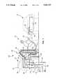
- FIG. 1is a simplified illustration of an liquified natural gas (LNG) fueling station.
- LNGliquified natural gas
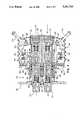
- FIG. 2is a cross-section of a fueling nozzle receptacle on the dispenser illustrated in FIG. 1 and a fueling nozzle.
- FIG. 3is a cross-section of a fueling nozzle docking with a receptacle on a motor vehicle for refueling.
- FIG. 4is a cross-section of the fueling nozzle latched to the receptacle on the motor vehicle after docking is completed to allow dispensing of LNG into vehicle to begin.
- FIGS. 2-4Please note that, because of space restrictions in FIGS. 2-4, only one of multiple like parts on the same drawing will be, in some cases, referenced with a numeral, due to the density of the illustrated parts. Where there are different numerals applying to otherwise like parts, it is to distinguish between symmetrical sides of the fueling nozzle.
- a liquified natural gas (LNG) fueling stationincludes dispenser 102, a cryogenic tank or vessel for storing a supply of LNG (not shown) and a pump (not shown) for pumping LNG from the tank to the dispenser 102 through a supply line 104.
- Dispenser 102includes a housing 106, and a control panel 108, both indicated in phantom for clarity.
- the control panelincludes a plurality of buttons 110 for controlling dispensing operations.
- Visual display 112indicates the volume of LNG dispensed from dispenser 102 as measured by liquid flow meter 114, as well as warning and advisory messages.
- LNG supply line 104is coupled to three-way valve 116.
- valve 116couples a flow of LNG from line 104 to a flexible hose 118 through line 120 and fitting 122.
- LNG return line 134is connected to the cryogenic tank.
- Return line 134is connected to dispenser receptacle 136, as well as to three-way valve 116.
- Vent line 124returns natural gas in its vapor phase, vented from vehicle fuel tank 140, to a venting system (not shown) associated with a cryogenic tank.
- Vent line 124is coupled to line 128, which in turn is connected to flexible hose 126 with fitting 130.
- a gas flow meter 132measures the flow rate of natural gas vented through flexible hose 126 to vent line 124.
- Fueling hose 118 and venting hose 126are each connected to fuel nozzle 138.
- Dispenser 136receives fueling nozzle 138 and establishes fluid communication between fueling hose 118 and return line 134.
- Dispenser 102has three basic modes of operation.
- a first mode of operationthree-way valve 116 is opened to allow a flow of LNG from supply line 104, past liquid flow meter 114 and into return line 134.
- liquid flow meter 114can be calibrated and cooled with LNG. Cooling flow meter 114 reduces vaporization. The phase of the LNG is thus more homogenous, allowing for more accurate measurement of initial flows by the flow meter.
- a second mode of operationreferred to as pre-cooling, the position of three-way valve 116 is moved to communicate a flow of LNG from supply line 104, through line 120, to hose 118.
- the LNGthen flows through the fueling nozzle 138 into receptacle 136 and into return line 134. Circulation of LNG through the fueling nozzle 138 and cools line 120, hose 118 and fueling nozzle 138. Pre-cooling of these elements reduces vaporization of LNG as it is being dispensed. A more homogenous phase is delivered, allowing for a more accurate measurement of the actual amount of LNG dispensed into the vehicle to be obtained and helping to insure that a saturated liquid phase of the cryogenic methane is delivered to the vehicle tank.
- the third mode of operationis dispensing of LNG into cryogenic tank 140 located in a vehicle 142.
- fueling nozzle 138has been removed from receptacle 136 and placed onto a vehicle receptacle 144.
- Hoses 118 and 126are suspended above the ground with bracket 146 on post 148 to allow easy manipulation of the fueling nozzle 138 by person 150.
- LNGflows through hose 118, through fueling nozzle 138 and into tank 140 through line 158.
- Gaseous methaneis vented from tank 140 through vent line 160 and collected by fueling nozzle 138.
- Gas flow meter 132measures the amount of gas vented from tank 140 and subtracts it from the total mass of LNG dispensed into vehicle 142 to obtain an accurate measurement of LNG in tank 140.
- Tank 152holds a supply of purging gas.
- Purging gasis supplied with line 154 to fueling nozzle 138.
- Purging gasis also supplied through hose 156 to dispenser receptacle 136.
- the purging gasbecause it will be vented to atmosphere, is an inert gas such as nitrogen (N 2 ).
- N 2nitrogen
- tank 152would not be necessary.
- a linecould be run from the venting mechanism associated with the LNG storage tank to a temporary holding tank from which the flow of purging gas is drawn. If used in small enough quantities, venting methane into the atmosphere may not pose a risk of explosion.
- fueling nozzle 138is shown as it is being removed from dispenser receptacle 136 located on fuel dispenser 102 (FIG. 1).
- Dispenser receptacle 136is recessed within housing 106 of the dispenser.
- Extending through holes defined in rear receptacle wall 202are male connectors 204 and 206.
- Male connector 204is attached to LNG return line 134 (see FIG. 1) with threaded end 211; connector 206 is sealed with cap 207 screwed onto threaded end 213.
- Each of the male connectorsare the same. Therefore, reference is made in this description only to one of the connectors.
- a flange portion 208 of the connectoris retained against the exterior of wall 202 with a ring 210.
- the male connectorincludes a cylindrically-shaped male connector body 214 having a hollow interior and a circular inner diameter.
- a valve 216is disposed in the interior of body 214 and has a distal end shaped to fit snugly against the inner diameter of the body to insure alignment with valve seat 220.
- a compressed spring 218, retained by a ring 219forces a proximal end of the valve against a valve seat 220 to close the valve.
- a force applied to a nipple portion 222sufficient to overcome the compressive force of spring 218 displaces valve 216 and allows fluid to flow through valve opening 226 and into annular cavity 224. From the annular cavity, fluid is allowed to flow into the interior of body 214 through ports 228.
- a shoulder 230extending from the inner surface of the connector body stops displacement of the valve 216.
- Male connectors 204 and 206are located within a compartment 233 formed by walls 232. As male connector 204 becomes very cold due to the flow of LNG circulating through the dispenser during pre-cooling, moisture in the air could freeze to the exterior of male connector 204, once fueling nozzle 138 is removed from dispenser receptacle 136 for dispensing. Ice on the male connectors may not have time to thaw and the water evaporate before fueling nozzle 138 is docked to the receptacle for pre-cooling between dispensing operations.
- Purge line 238supplies a flow of gas to compartment 233, as well as to space 240 between the walls 232 of the compartment and housing 106, displacing or purging air from compartment 233 and thereby reducing the opportunity for ice formation on the male connector 204.
- the purge lineis connected by threaded fitting 242 to hose 156 (FIG. 1), which is in turn connected to tank 152 (FIG. 1).
- the volume of the compartment 233is preferably kept relatively small to reduce the amount of purging gas required. The relatively small volume of the compartment also assists the purging gas in displacing air containing moisture from around male connectors 204 and 206.
- Flap 244shown in a closed position, further enhances purging by allowing purging gas to build up in the compartment 233 while permitting displaced air to escape.
- the flapis connected to the housing 106 is some manner to allow it to be swung or moved into the closed position after removal of fueling nozzle 138, and to an open position to allow fueling nozzle 138 to dock with dispenser receptacle 136.
- one or more slitsmay be incorporated in the flap, through the female connectors and or entire nozzle may be pushed.
- the flapis a rubber material, but may be made of metal or other material if desired. It does not seal tightly against housing 106 so as to permit air displaced by purging gas to exit the compartment 233 and space 240.
- Vehicle receptacle 144 on the vehicleis shown in place of dispenser receptacle 136.
- Vehicle receptacle 144is essentially identical to vehicle receptacle 144. Consequently, the same reference numbers are applied to the shared components of the receptacles, and no description of the elements so referenced is repeated. Nevertheless, there are several differences. Vehicle receptacle 144 has no need for its own purging system since it is not pre-cooled and ice will have sufficient time to melt during vehicle usage before docking again with the fueling nozzle.
- both male connectorsare used: threaded end 211 of male connector 204 is connected to line 158 (FIG. 1) for delivering LNG to tank 140 (FIG. 1); and threaded end 213 of male connector 206 is connected to vent line 160 (FIG. 1) for venting gas phase methane from the tank.
- the fueling nozzlehas four major components: female connectors 234 and 236; right and left latching handle assemblies 250 and 252, respectively; and boot 254.
- female connectors 234 and 236To threaded ends 256 and 258 of female connectors 234 and 236 are connected, respectively, to hose 118 (FIG. 1) for carrying LNG and hose 126 (FIG. 1) for carrying gas vented from vehicle fuel tank 140 (FIG. 1).
- the female connectors 234 and 236are essentially identical in structure and function. Therefore, reference to only one female connector will be made.
- the female connectorincludes a body 260.
- the hollow bodyincludes cylindrically shaped flange portion 262 that is designed to closely fit around the exterior of body 214 of the corresponding male connector 204 or 206.
- a pair of seals 263 disposed within a channel formed along the inner periphery or surface of the bodyprovide a seal between the body 260 and the exterior surface of body 214.
- Female connector body 260also includes a circular lip portion 264 extending inwardly that forms a valve seat having a back surface conforming to the surface of piston-like valve 246 to create a good seal.
- Valve 246moves linearly between a closed position against lip 264 and a fully open position against shoulder 261.
- the portion of body 260 carrying the valveis shaped and sized to snugly fit against the valve.
- the valveis displaced by force applied to nipple 269 on top of the valve. When the valve is displaced, fluid is allowed to flow through annular opening 267 and then through ports 265 into the hollow center of valve 246 and body 260.
- a flow of LNG through fueling nozzle 138turns the nozzle very cold. Consequently, after removal of the fueling nozzle from one of the receptacles 136 or 144, moisture in the air will tend to freeze on the mating surfaces of the fueling nozzle, particularly the interior surfaces of flange 262 and around valve 246. This ice will impede subsequent docking of the fueling circular lip portion 264 nozzle with another vehicle receptacle 144 or with dispenser receptacle 136. As the fueling nozzle is intended to undock for only short periods of time, and to quickly redock, this is a significant problem.
- a flow of dry purging gasis delivered to the interior of flange 262 through purge line 270 and branch 270a.
- Purge line 270is connected by threaded receptacle 272 to line 155 (FIG. 1) for receiving a flow of purging gas.
- This flow of purging gas into the interior of flange 262also tends to displace air from around the male connectors 204 and 206 of vehicle receptacle 144 during docking to prevent trapping of air having moisture between the male and female connectors that will subsequently freeze.
- the right and left latching handle assemblies 250 and 252are essentially identical in structure and function. In the following description, reference will be made to only one.
- the latching handle assemblyis mounted on a bottom back plate 277, on which female connectors 236 and 234 are also mounted.
- Handle 274rotates about pivot 276. Pivot 276 is fixed to back plate 272. Handle 274 includes a lever portion 278. Pivot 280 is fixed to the lever portion.
- Latching arm 282includes a linkage portion 284, a canted surface portion 286 and hook 288. Linkage portion 284 is attached for rotation to pivot 280. Canted surface portion 286 cooperates with sloped face 290 of body 260.
- the canted surface and sloped facecooperate, under the force of the piston, to move hook 288 forwardly and outwardly when latch arm 272 are is moved forwardly by rotation of handle 274 in the direction of arrow 292.
- Canted surface portion 286tends to pivot slightly against sloping face 290, as shown.
- Latching mechanisms 250 and 252are enclosed by a boot 254 made from flexible material capable of generally holding the purging gas or permitting a small flow of purging gas to escape.
- the bootincludes openings for the handles 274 and the end of latching arms, through which displaced air is allowed to escape.
- the material of the bootmay also be porous enough to allow escape of the air.
- purge line 270a flow of purging gas displaces air within the boot and fills the boot with the purging gas. Enveloping the exterior surfaces of the latching mechanisms 250 and 252 prevents moisture in the air from freezing to linages, pivots and other cooperating surfaces of the latching mechanisms when a flow of LNG through the nozzle cools the entire nozzle.
- FIG. 3docking of the fueling nozzle 138 with vehicle receptacle 144 is illustrated.
- Vehicle receptacle 144is mounted on a bulkhead 301 of vehicle 142 (FIG. 1). Docking of the fueling nozzle with receptacle 136 on the dispenser 102 (see FIGS. 1 and 2) is identical, and therefore will not be separately described.
- Person 150maneuvers fueling nozzle 138 to the receptacle by gripping left and right handles 274 and moving them inwardly, in the direction indicated by arrows 292, to move hooks 288 forwardly and outwardly with respect to female connectors 234 and 236.
- the nipplesare displaced upon further sliding of the female connectors over the male connectors caused by motion of the handles 274 in the direction of arrows 402. Rotation of the handles causes each hook 288 to engage wall 304. Further rotation pulls the fueling nozzle 138 onto vehicle receptacle 144.
- the valve having the weaker biasing springwill open first. The springs may be chosen to ensure that a particular valve opens first, if desired. Seals 263 prevent fluid spillage of LNG and vent gas from around male connectors 204 and 206, respectively, in the event valve 246 on female connector 234 and valve 216 on male connector open before the valve with which they mate opens to receive the flow of LNG or vent gas.
- fueling nozzle 138is shown fully docked and latched to vehicle receptacle 144.
- the final stages of docking, as well as latching and undocking,are the same for receptacle 136, and therefore these procedures will be described with reference only to vehicle receptacle 144.
- Each hookincludes a canted or oblique face 406 to help to find and to push the hooks through slots 302 without the forward surface of the hooks from catching wall 304.
- the hookis then pulled backwardly and inwardly by rotation of handle 274 in the directions shown by arrow 402. As the hook grabs wall 304, continued rotation of the handle pulls fueling nozzle 138 toward the receptacle.
- the handlethus provides leverage for assisting docking. This leverage is helpful where seals 263 provide a very tight fit between the outer diameter of male connectors 204 and 206 and the inner diameter of cylindrical flanges 262.
- the handle 274is rotated until elbow 408 of the latching arm 282 hits against pivot 276. Rotating handle 274 to this point moves pivot 280 slightly outside the direction of force applied by the latching arm 282 to wall 304, taking advantage of the pulling force exerted along latching arm 282 to hold the handle in a fully-outwardly rotated position.
- face 410 of boot 254is flush against wall 304 to assist in trapping purging gas in compartment 233 that has flowed from branch 270a and into the compartment during earlier stages of docking.
- the flush fitalso assists in preventing moisture-laden air from entering the compartment.
- Valves 216 and 246are both fully open to allow flow of LNG through female connector 234 and into through the male and female connectors, seals 263 create a seal between the male and female connectors.
- handle 274To unlatch the fueling nozzle, handle 274 is moved in the direction opposite of that indicated by arrow 402, causing hook 288 to move first outwardly and then forwardly. Once hook 288 hits tab 404, continued rotation of the handle acts to push fueling nozzle 138 away from vehicle receptacle 144.
- the leverage supplied by the handleassists in removing the fueling nozzle in the event some ice does form around the mating surfaces (the exterior surface of body 214 and interior surface of cylindrical flange 262) of the connectors or between the exterior of the female bodies 260 and walls 232.
Landscapes
- Engineering & Computer Science (AREA)
- Mechanical Engineering (AREA)
- General Engineering & Computer Science (AREA)
- Filling Or Discharging Of Gas Storage Vessels (AREA)
Abstract
Description
Claims (23)
Priority Applications (1)
| Application Number | Priority Date | Filing Date | Title |
|---|---|---|---|
| US07/973,159US5301723A (en) | 1992-11-06 | 1992-11-06 | Apparatus and method of preventing ice accumulation on coupling valves for cryogenic fluids |
Applications Claiming Priority (1)
| Application Number | Priority Date | Filing Date | Title |
|---|---|---|---|
| US07/973,159US5301723A (en) | 1992-11-06 | 1992-11-06 | Apparatus and method of preventing ice accumulation on coupling valves for cryogenic fluids |
Publications (1)
| Publication Number | Publication Date |
|---|---|
| US5301723Atrue US5301723A (en) | 1994-04-12 |
Family
ID=25520572
Family Applications (1)
| Application Number | Title | Priority Date | Filing Date |
|---|---|---|---|
| US07/973,159Expired - LifetimeUS5301723A (en) | 1992-11-06 | 1992-11-06 | Apparatus and method of preventing ice accumulation on coupling valves for cryogenic fluids |
Country Status (1)
| Country | Link |
|---|---|
| US (1) | US5301723A (en) |
Cited By (66)
| Publication number | Priority date | Publication date | Assignee | Title |
|---|---|---|---|---|
| EP0659254A4 (en)* | 1993-05-19 | 1995-08-02 | Moog Inc. | Cryogenic fluid coupling. |
| US5603360A (en)* | 1995-05-30 | 1997-02-18 | Teel; James R. | Method and system for transporting natural gas from a pipeline to a compressed natural gas automotive re-fueling station |
| US5690153A (en)* | 1995-09-05 | 1997-11-25 | Mercedes-Benz Ag | Filling system for robot-capable filling of a vehicle with fuel |
| US5690154A (en)* | 1995-09-05 | 1997-11-25 | Mercedes-Benz Ag | Filling system for robot-capable filling of a vehicle with fuel |
| WO1998006627A1 (en)* | 1996-08-13 | 1998-02-19 | Argonaut Technologies, Inc. | Closure device for a vessel |
| US5740846A (en)* | 1996-10-11 | 1998-04-21 | Larson; L. Robert | Hose adapter for use in connecting a proconditioned air hose to an aircraft |
| US5765602A (en)* | 1992-05-27 | 1998-06-16 | Cryogenic Fuels Inc. | Apparatus and method for metering and transfer of cryogenic liquids |
| US5816298A (en)* | 1994-05-10 | 1998-10-06 | Scholle Corporation | Two-part fluid coupling with guide structure |
| US5906102A (en)* | 1996-04-12 | 1999-05-25 | Helix Technology Corporation | Cryopump with gas heated exhaust valve and method of warming surfaces of an exhaust valve |
| US6196280B1 (en)* | 1999-08-17 | 2001-03-06 | Liberty Fuels, Inc. | Combination nozzle and fuel tank fitting for delivering liquefied natural gas and components thereof |
| US6370738B1 (en)* | 1998-07-10 | 2002-04-16 | Tokheim Corporation | Flexible conduit tubing system within dispenser |
| US6371443B1 (en)* | 1999-02-12 | 2002-04-16 | Surpass Industry Co., Ltd. | Socket for liquid material or the like transferring connector |
| US6382273B1 (en)* | 1996-09-11 | 2002-05-07 | Weh Gmbh Verbindungstechnik | Fuelling fixture |
| US6395235B1 (en) | 1998-08-21 | 2002-05-28 | Argonaut Technologies, Inc. | Devices and methods for accessing reaction vessels |
| US6561237B1 (en)* | 2000-11-28 | 2003-05-13 | Brasscorp Ltd. | Apparatus and method for urging fluid into a pressurized system |
| US6675841B2 (en)* | 2000-12-12 | 2004-01-13 | Snap-Tite Technologies, Inc. | Fuel storage tank coupling with vapor recovery |
| US20040016240A1 (en)* | 2002-04-02 | 2004-01-29 | Brook Thomas Currie | Method for transferring cryogenic liquids and associated cryogenic fill nozzle insulating boot |
| US20040250871A1 (en)* | 2003-05-09 | 2004-12-16 | Bingham Dennis A. | Method and apparatus for dispensing compressed natural gas and liquified natural gas to natural gas powered vehicles |
| US20050147513A1 (en)* | 2001-11-30 | 2005-07-07 | Noble Stephen D. | Method and apparatus for delivering pressurized gas |
| US20060026969A1 (en)* | 2003-04-01 | 2006-02-09 | Brook Thomas C | Method for transferring cryogenic liquids and associated cryogenic fill nozzle insulating boot |
| US7000657B1 (en)* | 2005-01-19 | 2006-02-21 | Thorpe Douglas G | Interlocking fuel nozzle |
| US7082969B1 (en)* | 2005-01-28 | 2006-08-01 | Hollerback Christopher J | Total containment fluid delivery system |
| WO2006091234A3 (en)* | 2004-07-27 | 2006-10-19 | Parker Hannifin Corp | Quick disconnect cryogenic coupler |
| US20070251781A1 (en)* | 2006-04-28 | 2007-11-01 | International Truck Intellectual Property Company, Llc | Remote drain valve device for an air brake vehicle |
| US20070277905A1 (en)* | 2003-11-19 | 2007-12-06 | Erwin Weh | Actuating Device for a Rapid Coupling |
| US20090167019A1 (en)* | 2005-05-21 | 2009-07-02 | Erwin Weh | Actuating device for a rapid coupling |
| US20090255532A1 (en)* | 2008-04-09 | 2009-10-15 | Baxter International Inc. | Adapters for use with an anesthetic vaporizer |
| DE202009006150U1 (en)* | 2009-04-28 | 2010-09-23 | Apel, Helga | Tank system for aggressive liquids, especially urea |
| US20120024421A1 (en)* | 2009-03-30 | 2012-02-02 | Eric Boutet | Device for fueling launcher thrusters |
| US20130061983A1 (en)* | 2011-09-14 | 2013-03-14 | Toyota Jidosha Kabushiki Kaisha | Suction nozzle, suction device, gas filling device, gas consuming device and gas filling system |
| US20130340858A1 (en)* | 2012-06-21 | 2013-12-26 | Shih-Hsun Chang | Gas Hood for Gas Regulator |
| US8844587B1 (en)* | 2013-11-01 | 2014-09-30 | James A. McCommons | Locking fuel pump dispenser |
| US20140345708A1 (en)* | 2013-05-24 | 2014-11-27 | Clean Energy Fuels Corp. | Dispenser nitrogen purge |
| EP2902687A1 (en)* | 2014-02-03 | 2015-08-05 | RUAG Schweiz AG | Cryogenic connector |
| US20160195220A1 (en)* | 2011-10-20 | 2016-07-07 | Rht Railhaul Technologies | Multi-Fuel Service Station |
| CN105980764A (en)* | 2014-04-04 | 2016-09-28 | 株式会社龙野 | Liquefied natural gas filling device |
| US9527720B2 (en) | 2014-12-18 | 2016-12-27 | Opw Fueling Components Inc. | Nozzle for dispensing pressurized fluid |
| FR3043166A1 (en)* | 2015-11-03 | 2017-05-05 | Air Liquide | METHOD FOR CLEANING AND BLOWING DEHUMIDIFICATION OF CRYOGENIC FLUID TRANSFER FITTINGS APPLIED TO REFRIGERATION TRANSPORT |
| US9644447B2 (en) | 2011-12-07 | 2017-05-09 | National Oilwell Varco Uk Limited | Wireline pressure control apparatus |
| US9732893B2 (en) | 2010-08-10 | 2017-08-15 | Engineered Controls International, Llc | Rapid-connect coupler |
| US9758033B1 (en)* | 2017-03-06 | 2017-09-12 | A3 Labs, Llc | Mobile fueling system and method |
| US9791081B2 (en) | 2015-04-30 | 2017-10-17 | Opw-Engineered Systems, Inc. | Fluid system connection nozzle assembly |
| US20170341769A1 (en)* | 2016-05-29 | 2017-11-30 | Neoex Systems, Inc. | System and method for the transfer of cryogenic fluids |
| US9841143B2 (en)* | 2014-07-09 | 2017-12-12 | Toyota Jidosha Kabushiki Kaisha | Suction device and suction method |
| US9857010B2 (en)* | 2011-03-21 | 2018-01-02 | Engineered Controls International, Llc | Rapid-connect coupler with vent-stop |
| US9897239B2 (en) | 2015-04-27 | 2018-02-20 | Engineered Controls International, Llc | Rapid-connect coupler with vent stop |
| EP3299775A1 (en)* | 2016-09-26 | 2018-03-28 | Tatsuno Corporation | Calibration device |
| CN107957291A (en)* | 2016-10-14 | 2018-04-24 | 株式会社龙野 | Calibrating installation |
| US20180266633A1 (en)* | 2017-03-15 | 2018-09-20 | Toyota Jidosha Kabushiki Kaisha | Vehicle and method for filling fuel gas |
| US10295516B2 (en) | 2015-09-28 | 2019-05-21 | Tatsuno Corporation | Calibration device |
| US10337905B2 (en) | 2015-09-28 | 2019-07-02 | Tatsuno Corporation | Calibration device and calibration method |
| US10386017B2 (en) | 2015-12-03 | 2019-08-20 | Engineered Controls International, Llc | Low emission nozzles and receptacles |
| CN110425327A (en)* | 2019-08-21 | 2019-11-08 | 山西新思备科技股份有限公司 | The rotary limit of impact removes wink valve opening |
| CN110864219A (en)* | 2019-10-16 | 2020-03-06 | 北京航天试验技术研究所 | Liquid hydrogen filling device |
| US10998561B1 (en)* | 2019-10-23 | 2021-05-04 | Hyundai Motor Company | Hydrogen filling system |
| US20210301982A1 (en)* | 2020-03-30 | 2021-09-30 | Hyundai Motor Company | Fluid charging system, nozzle device, and receptacle device |
| EP3961082A1 (en)* | 2020-08-31 | 2022-03-02 | Salzburger Aluminium Aktiengesellschaft | Connection fitting, filling system and dispenser |
| WO2022047409A1 (en) | 2020-08-31 | 2022-03-03 | Ysn Imports, Llc | Quick-fill apparatus, system and method for fuel valves |
| WO2022069076A1 (en)* | 2020-10-02 | 2022-04-07 | Linde Gmbh | Method for operating a cryogenic fuelling arrangement |
| WO2022069078A1 (en)* | 2020-10-02 | 2022-04-07 | Linde Gmbh | Cryogenic tank filling arrangement and method |
| WO2022187603A1 (en)* | 2021-03-04 | 2022-09-09 | Chart Inc. | Cryogenic fluid coupling |
| SE2150509A1 (en)* | 2021-04-22 | 2022-10-23 | Mann Teknik Ab | Device and method for drying a nozzle for liquified gas |
| US12011989B1 (en) | 2021-01-17 | 2024-06-18 | Neoex Systems, Inc. | Direct liquefaction for vehicle refueling |
| US20240309980A1 (en)* | 2023-03-17 | 2024-09-19 | H2CREO Corp. | Two-way twin-axial connector module of a receptacle for transporting liquefied gas and liquefied gas transport system including the same |
| EP4521016A1 (en)* | 2023-09-07 | 2025-03-12 | L'air Liquide, Societe Anonyme Pour L'etude Et L'exploitation Des Procedes Georges Claude | Receptacle for cryogenic connector and assembly comprising such a receptacle |
| US12429153B2 (en)* | 2021-05-28 | 2025-09-30 | Engineered Controls International, Llc | Low-emission nozzle and receptacle coupling for cryogenic fluid |
Citations (8)
| Publication number | Priority date | Publication date | Assignee | Title |
|---|---|---|---|---|
| US3045721A (en)* | 1960-02-04 | 1962-07-24 | Dover Corp | Under-wing fueling nozzle |
| US3086565A (en)* | 1959-05-14 | 1963-04-23 | Schulz Tool & Mfg Co | Servicing nozzle |
| US3863688A (en)* | 1973-06-18 | 1975-02-04 | Parker Hannifin Corp | Convertor for top loading tanks |
| US4098303A (en)* | 1976-09-17 | 1978-07-04 | Robert Brown Associates | Vapor recovery system for loading backs and storage tanks |
| US4489767A (en)* | 1981-09-08 | 1984-12-25 | Toyo Seikan Kaisha, Ltd. | Apparatus for dropping liquefied gases |
| US4582100A (en)* | 1982-09-30 | 1986-04-15 | Aga, A.B. | Filling of acetylene cylinders |
| US4827992A (en)* | 1987-10-23 | 1989-05-09 | Neste Oy | Method for conducting a fluid into a rock cistern |
| US5094277A (en)* | 1989-06-27 | 1992-03-10 | Ashland Oil Inc. | Direct condensation refrigerant recovery and restoration system |
- 1992
- 1992-11-06USUS07/973,159patent/US5301723A/ennot_activeExpired - Lifetime
Patent Citations (8)
| Publication number | Priority date | Publication date | Assignee | Title |
|---|---|---|---|---|
| US3086565A (en)* | 1959-05-14 | 1963-04-23 | Schulz Tool & Mfg Co | Servicing nozzle |
| US3045721A (en)* | 1960-02-04 | 1962-07-24 | Dover Corp | Under-wing fueling nozzle |
| US3863688A (en)* | 1973-06-18 | 1975-02-04 | Parker Hannifin Corp | Convertor for top loading tanks |
| US4098303A (en)* | 1976-09-17 | 1978-07-04 | Robert Brown Associates | Vapor recovery system for loading backs and storage tanks |
| US4489767A (en)* | 1981-09-08 | 1984-12-25 | Toyo Seikan Kaisha, Ltd. | Apparatus for dropping liquefied gases |
| US4582100A (en)* | 1982-09-30 | 1986-04-15 | Aga, A.B. | Filling of acetylene cylinders |
| US4827992A (en)* | 1987-10-23 | 1989-05-09 | Neste Oy | Method for conducting a fluid into a rock cistern |
| US5094277A (en)* | 1989-06-27 | 1992-03-10 | Ashland Oil Inc. | Direct condensation refrigerant recovery and restoration system |
Cited By (115)
| Publication number | Priority date | Publication date | Assignee | Title |
|---|---|---|---|---|
| US5996649A (en)* | 1992-05-27 | 1999-12-07 | Cryogenic Fuels, Inc. | Apparatus and method for metering and transfer of cryogenic liquids |
| US5765602A (en)* | 1992-05-27 | 1998-06-16 | Cryogenic Fuels Inc. | Apparatus and method for metering and transfer of cryogenic liquids |
| EP0659254A4 (en)* | 1993-05-19 | 1995-08-02 | Moog Inc. | Cryogenic fluid coupling. |
| US5816298A (en)* | 1994-05-10 | 1998-10-06 | Scholle Corporation | Two-part fluid coupling with guide structure |
| US5603360A (en)* | 1995-05-30 | 1997-02-18 | Teel; James R. | Method and system for transporting natural gas from a pipeline to a compressed natural gas automotive re-fueling station |
| US5690153A (en)* | 1995-09-05 | 1997-11-25 | Mercedes-Benz Ag | Filling system for robot-capable filling of a vehicle with fuel |
| US5690154A (en)* | 1995-09-05 | 1997-11-25 | Mercedes-Benz Ag | Filling system for robot-capable filling of a vehicle with fuel |
| US5906102A (en)* | 1996-04-12 | 1999-05-25 | Helix Technology Corporation | Cryopump with gas heated exhaust valve and method of warming surfaces of an exhaust valve |
| WO1998006627A1 (en)* | 1996-08-13 | 1998-02-19 | Argonaut Technologies, Inc. | Closure device for a vessel |
| US5848622A (en)* | 1996-08-13 | 1998-12-15 | Argonaut Technologies Incorporated | Closure device and method for venting, cannulating and pressurizing a vessel |
| US5806573A (en)* | 1996-08-13 | 1998-09-15 | Argonaut Technologies Incorporated | Closure device and method for venting, cannulating and pressurizing a vessel |
| US6382273B1 (en)* | 1996-09-11 | 2002-05-07 | Weh Gmbh Verbindungstechnik | Fuelling fixture |
| US5740846A (en)* | 1996-10-11 | 1998-04-21 | Larson; L. Robert | Hose adapter for use in connecting a proconditioned air hose to an aircraft |
| US6370738B1 (en)* | 1998-07-10 | 2002-04-16 | Tokheim Corporation | Flexible conduit tubing system within dispenser |
| US6395235B1 (en) | 1998-08-21 | 2002-05-28 | Argonaut Technologies, Inc. | Devices and methods for accessing reaction vessels |
| US6371443B1 (en)* | 1999-02-12 | 2002-04-16 | Surpass Industry Co., Ltd. | Socket for liquid material or the like transferring connector |
| US6196280B1 (en)* | 1999-08-17 | 2001-03-06 | Liberty Fuels, Inc. | Combination nozzle and fuel tank fitting for delivering liquefied natural gas and components thereof |
| US20030178098A1 (en)* | 2000-11-28 | 2003-09-25 | Jack Brass | Apparatus and method for urging fluid into a pressurized system |
| US6561237B1 (en)* | 2000-11-28 | 2003-05-13 | Brasscorp Ltd. | Apparatus and method for urging fluid into a pressurized system |
| US20070125443A1 (en)* | 2000-11-28 | 2007-06-07 | Jack Brass | Apparatus And Method For Urging Fluid Into A Pressurized System |
| US7174929B2 (en) | 2000-11-28 | 2007-02-13 | Brasscorp Ltd. | Apparatus and method for urging fluid into a pressurized system |
| US6926048B2 (en) | 2000-11-28 | 2005-08-09 | Brasscorp Ltd. | Apparatus and method for urging fluid into a pressurized system |
| US20050279422A1 (en)* | 2000-11-28 | 2005-12-22 | Jack Brass | Apparatus and method for urging fluid into a pressurized system |
| US6675841B2 (en)* | 2000-12-12 | 2004-01-13 | Snap-Tite Technologies, Inc. | Fuel storage tank coupling with vapor recovery |
| US20050147513A1 (en)* | 2001-11-30 | 2005-07-07 | Noble Stephen D. | Method and apparatus for delivering pressurized gas |
| US7607898B2 (en) | 2001-11-30 | 2009-10-27 | Westport Power Inc. | Method and apparatus for delivering pressurized gas |
| US20040016240A1 (en)* | 2002-04-02 | 2004-01-29 | Brook Thomas Currie | Method for transferring cryogenic liquids and associated cryogenic fill nozzle insulating boot |
| US6923008B2 (en) | 2002-04-02 | 2005-08-02 | Westpoint Research Inc. | Method for transferring cryogenic liquids and associated cryogenic fill nozzle insulating boot |
| US20060026969A1 (en)* | 2003-04-01 | 2006-02-09 | Brook Thomas C | Method for transferring cryogenic liquids and associated cryogenic fill nozzle insulating boot |
| US6899146B2 (en) | 2003-05-09 | 2005-05-31 | Battelle Energy Alliance, Llc | Method and apparatus for dispensing compressed natural gas and liquified natural gas to natural gas powered vehicles |
| US20060169352A1 (en)* | 2003-05-09 | 2006-08-03 | Bingham Dennis A | Apparatus for dispensing compressed natural gas and liquified natural gas to natural gas powered vehicles |
| US7222647B2 (en) | 2003-05-09 | 2007-05-29 | Battelle Energy Alliance, Llc | Apparatus for dispensing compressed natural gas and liquified natural gas to natural gas powered vehicles |
| US20040250871A1 (en)* | 2003-05-09 | 2004-12-16 | Bingham Dennis A. | Method and apparatus for dispensing compressed natural gas and liquified natural gas to natural gas powered vehicles |
| US8033305B2 (en)* | 2003-11-19 | 2011-10-11 | Erwin Weh | Actuating device for a rapid coupling |
| US20070277905A1 (en)* | 2003-11-19 | 2007-12-06 | Erwin Weh | Actuating Device for a Rapid Coupling |
| WO2006091234A3 (en)* | 2004-07-27 | 2006-10-19 | Parker Hannifin Corp | Quick disconnect cryogenic coupler |
| US7000657B1 (en)* | 2005-01-19 | 2006-02-21 | Thorpe Douglas G | Interlocking fuel nozzle |
| US7082969B1 (en)* | 2005-01-28 | 2006-08-01 | Hollerback Christopher J | Total containment fluid delivery system |
| US20060169350A1 (en)* | 2005-01-28 | 2006-08-03 | Hollerback Christopher J | Total containment fluid delivery system |
| WO2006083554A1 (en)* | 2005-01-28 | 2006-08-10 | Hollerback Christopher J | Total containment fluid delivery system |
| US20090167019A1 (en)* | 2005-05-21 | 2009-07-02 | Erwin Weh | Actuating device for a rapid coupling |
| US8028727B2 (en)* | 2005-05-21 | 2011-10-04 | Erwin Weh | Actuating device for a rapid coupling |
| US20070251781A1 (en)* | 2006-04-28 | 2007-11-01 | International Truck Intellectual Property Company, Llc | Remote drain valve device for an air brake vehicle |
| US20090255532A1 (en)* | 2008-04-09 | 2009-10-15 | Baxter International Inc. | Adapters for use with an anesthetic vaporizer |
| US8534328B2 (en)* | 2008-04-09 | 2013-09-17 | Baxter International Inc. | Adapters for use with an anesthetic vaporizer |
| US8991444B2 (en)* | 2009-03-30 | 2015-03-31 | Snecma | Device for fueling launcher thrusters |
| US20120024421A1 (en)* | 2009-03-30 | 2012-02-02 | Eric Boutet | Device for fueling launcher thrusters |
| DE202009006150U1 (en)* | 2009-04-28 | 2010-09-23 | Apel, Helga | Tank system for aggressive liquids, especially urea |
| US9732893B2 (en) | 2010-08-10 | 2017-08-15 | Engineered Controls International, Llc | Rapid-connect coupler |
| US10281073B2 (en) | 2010-08-10 | 2019-05-07 | Engineered Controls International, Llc | Rapid-connect coupler |
| US10718456B2 (en) | 2011-03-21 | 2020-07-21 | Engineered Controls International, Llc | Rapid-connect coupler with vent-stop |
| US9857010B2 (en)* | 2011-03-21 | 2018-01-02 | Engineered Controls International, Llc | Rapid-connect coupler with vent-stop |
| US20130061983A1 (en)* | 2011-09-14 | 2013-03-14 | Toyota Jidosha Kabushiki Kaisha | Suction nozzle, suction device, gas filling device, gas consuming device and gas filling system |
| DE112011104868B4 (en)* | 2011-09-14 | 2017-11-02 | Toyota Jidosha Kabushiki Kaisha | SUCTION NOZZLE, SUCTION DEVICE AND GAS FILLING DEVICE |
| US8776843B2 (en)* | 2011-09-14 | 2014-07-15 | Toyota Jidosha Kabushiki Kaisha | Suction nozzle, suction device, gas filling device, gas consuming device and gas filling system |
| US9739419B2 (en)* | 2011-10-20 | 2017-08-22 | Rht Railhaul Technologies | Multi-fuel service station |
| US20160195220A1 (en)* | 2011-10-20 | 2016-07-07 | Rht Railhaul Technologies | Multi-Fuel Service Station |
| US9644447B2 (en) | 2011-12-07 | 2017-05-09 | National Oilwell Varco Uk Limited | Wireline pressure control apparatus |
| US9341313B2 (en)* | 2012-06-21 | 2016-05-17 | United Microelectronics Corp. | Gas hood for gas regulator |
| US20130340858A1 (en)* | 2012-06-21 | 2013-12-26 | Shih-Hsun Chang | Gas Hood for Gas Regulator |
| US20140345708A1 (en)* | 2013-05-24 | 2014-11-27 | Clean Energy Fuels Corp. | Dispenser nitrogen purge |
| US8844587B1 (en)* | 2013-11-01 | 2014-09-30 | James A. McCommons | Locking fuel pump dispenser |
| EP2902687A1 (en)* | 2014-02-03 | 2015-08-05 | RUAG Schweiz AG | Cryogenic connector |
| CN105980764A (en)* | 2014-04-04 | 2016-09-28 | 株式会社龙野 | Liquefied natural gas filling device |
| US10012349B2 (en)* | 2014-04-04 | 2018-07-03 | Tatsuno Corporation | Liquefied natural gas filling device |
| CN105980764B (en)* | 2014-04-04 | 2018-09-25 | 株式会社龙野 | Liquefied natural gas filling device |
| EP3128222A4 (en)* | 2014-04-04 | 2017-12-13 | Tatsuno Corporation | Liquefied natural gas filling device |
| US20170009939A1 (en)* | 2014-04-04 | 2017-01-12 | Tatsuno Corporation | Liquefied natural gas filling device |
| US9841143B2 (en)* | 2014-07-09 | 2017-12-12 | Toyota Jidosha Kabushiki Kaisha | Suction device and suction method |
| US9527720B2 (en) | 2014-12-18 | 2016-12-27 | Opw Fueling Components Inc. | Nozzle for dispensing pressurized fluid |
| US9897239B2 (en) | 2015-04-27 | 2018-02-20 | Engineered Controls International, Llc | Rapid-connect coupler with vent stop |
| US10208877B2 (en) | 2015-04-27 | 2019-02-19 | Engineered Controls International, Llc | Rapid-connect coupler with vent stop |
| US9791081B2 (en) | 2015-04-30 | 2017-10-17 | Opw-Engineered Systems, Inc. | Fluid system connection nozzle assembly |
| US10760723B2 (en) | 2015-04-30 | 2020-09-01 | OPW—Engineered Systems, Inc. | Fluid system connection nozzle assembly |
| US10337905B2 (en) | 2015-09-28 | 2019-07-02 | Tatsuno Corporation | Calibration device and calibration method |
| US10295516B2 (en) | 2015-09-28 | 2019-05-21 | Tatsuno Corporation | Calibration device |
| FR3043166A1 (en)* | 2015-11-03 | 2017-05-05 | Air Liquide | METHOD FOR CLEANING AND BLOWING DEHUMIDIFICATION OF CRYOGENIC FLUID TRANSFER FITTINGS APPLIED TO REFRIGERATION TRANSPORT |
| EP3171071A1 (en)* | 2015-11-03 | 2017-05-24 | L'air Liquide, Societe Anonyme Pour L'etude Et L'exploitation Des Procedes Georges Claude | Method for cleaning and dehumidification by blowing cryogenic fluid transfer couplings applied to refrigerated transport |
| US11796135B2 (en) | 2015-12-03 | 2023-10-24 | Engineered Controls International, Llc | Low emission receptacles |
| US12297961B2 (en) | 2015-12-03 | 2025-05-13 | Engineered Controls International, Llc | Low emission receptacles |
| US10386017B2 (en) | 2015-12-03 | 2019-08-20 | Engineered Controls International, Llc | Low emission nozzles and receptacles |
| US11162641B2 (en) | 2015-12-03 | 2021-11-02 | Engineered Controls International | Low emission nozzles and receptacles |
| US10883665B2 (en) | 2015-12-03 | 2021-01-05 | Engineered Controls International, Llc | Low emission nozzles and receptacles |
| US10981666B1 (en)* | 2016-05-29 | 2021-04-20 | Neoex Systems, Inc. | System and method for the transfer of cryogenic fluids |
| US11286055B2 (en)* | 2016-05-29 | 2022-03-29 | Neoex Systems, Inc. | System and method for the transfer of cryogenic fluids |
| US20170341769A1 (en)* | 2016-05-29 | 2017-11-30 | Neoex Systems, Inc. | System and method for the transfer of cryogenic fluids |
| US10773822B2 (en)* | 2016-05-29 | 2020-09-15 | Neoex Systems, Inc. | System and method for the transfer of cryogenic fluids |
| EP3299775A1 (en)* | 2016-09-26 | 2018-03-28 | Tatsuno Corporation | Calibration device |
| CN107957291A (en)* | 2016-10-14 | 2018-04-24 | 株式会社龙野 | Calibrating installation |
| US10035418B1 (en)* | 2017-03-06 | 2018-07-31 | A3 Labs LLC | Mobile fueling system and method |
| US9758033B1 (en)* | 2017-03-06 | 2017-09-12 | A3 Labs, Llc | Mobile fueling system and method |
| USRE50108E1 (en)* | 2017-03-06 | 2024-09-03 | A3 Labs, Llc | Mobile fueling system and method |
| US20180266633A1 (en)* | 2017-03-15 | 2018-09-20 | Toyota Jidosha Kabushiki Kaisha | Vehicle and method for filling fuel gas |
| US10995913B2 (en)* | 2017-03-15 | 2021-05-04 | Toyota Jidosha Kabushiki Kaisha | Vehicle and method for filling fuel gas |
| CN110425327A (en)* | 2019-08-21 | 2019-11-08 | 山西新思备科技股份有限公司 | The rotary limit of impact removes wink valve opening |
| CN110864219A (en)* | 2019-10-16 | 2020-03-06 | 北京航天试验技术研究所 | Liquid hydrogen filling device |
| US10998561B1 (en)* | 2019-10-23 | 2021-05-04 | Hyundai Motor Company | Hydrogen filling system |
| US11668438B2 (en)* | 2020-03-30 | 2023-06-06 | Hyundai Motor Company | Fluid charging system, nozzle device, and receptacle device |
| US20210301982A1 (en)* | 2020-03-30 | 2021-09-30 | Hyundai Motor Company | Fluid charging system, nozzle device, and receptacle device |
| CN116391091A (en)* | 2020-08-31 | 2023-07-04 | 外思恩进口有限责任公司 | Rapid fill device, system and method for a fuel valve |
| EP3961082A1 (en)* | 2020-08-31 | 2022-03-02 | Salzburger Aluminium Aktiengesellschaft | Connection fitting, filling system and dispenser |
| WO2022047409A1 (en) | 2020-08-31 | 2022-03-03 | Ysn Imports, Llc | Quick-fill apparatus, system and method for fuel valves |
| EP4204306A4 (en)* | 2020-08-31 | 2024-12-11 | YSN Imports, LLC | QUICK FILLING DEVICE, SYSTEM AND METHOD FOR FUEL VALVES |
| WO2022069078A1 (en)* | 2020-10-02 | 2022-04-07 | Linde Gmbh | Cryogenic tank filling arrangement and method |
| WO2022069076A1 (en)* | 2020-10-02 | 2022-04-07 | Linde Gmbh | Method for operating a cryogenic fuelling arrangement |
| US12011989B1 (en) | 2021-01-17 | 2024-06-18 | Neoex Systems, Inc. | Direct liquefaction for vehicle refueling |
| WO2022187603A1 (en)* | 2021-03-04 | 2022-09-09 | Chart Inc. | Cryogenic fluid coupling |
| US12331884B2 (en) | 2021-03-04 | 2025-06-17 | Chart Inc. | Cryogenic fluid coupling |
| SE2150509A1 (en)* | 2021-04-22 | 2022-10-23 | Mann Teknik Ab | Device and method for drying a nozzle for liquified gas |
| SE546460C2 (en)* | 2021-04-22 | 2024-11-05 | Mann Teknik Ab | Device and method for drying a nozzle for liquified gas |
| US12429153B2 (en)* | 2021-05-28 | 2025-09-30 | Engineered Controls International, Llc | Low-emission nozzle and receptacle coupling for cryogenic fluid |
| US20240309980A1 (en)* | 2023-03-17 | 2024-09-19 | H2CREO Corp. | Two-way twin-axial connector module of a receptacle for transporting liquefied gas and liquefied gas transport system including the same |
| US12429157B2 (en)* | 2023-03-17 | 2025-09-30 | H2CREO Corp. | Two-way twin-axial connector module of a receptacle for transporting liquefied gas and liquefied gas transport system including the same |
| FR3152859A1 (en)* | 2023-09-07 | 2025-03-14 | L'air Liquide, Societe Anonyme Pour L'etude Et L'exploitation Des Procedes Georges Claude | Receptacle for cryogenic connection and assembly comprising such a receptacle |
| EP4521016A1 (en)* | 2023-09-07 | 2025-03-12 | L'air Liquide, Societe Anonyme Pour L'etude Et L'exploitation Des Procedes Georges Claude | Receptacle for cryogenic connector and assembly comprising such a receptacle |
Similar Documents
| Publication | Publication Date | Title |
|---|---|---|
| US5301723A (en) | Apparatus and method of preventing ice accumulation on coupling valves for cryogenic fluids | |
| US9969605B2 (en) | Liquid natural gas gun-style nozzle | |
| US5404909A (en) | Coupling device | |
| US5429155A (en) | Cryogenic fluid coupling | |
| US6945477B2 (en) | Cryogenic coupling device | |
| US20220282837A1 (en) | Cryogenic fluid coupling | |
| US3171448A (en) | Fluid connection | |
| EP3511603B1 (en) | Rapid-connect coupler with vent-stop | |
| KR102259492B1 (en) | Liquid natural gas transfer | |
| US20060169350A1 (en) | Total containment fluid delivery system | |
| KR102254267B1 (en) | Connection device for connecting two fluid circuits | |
| US5295521A (en) | Self-contained fuel filler system | |
| WO2024073668A1 (en) | Boil-off shielded coupling for hydrogen tank filling | |
| US20050199297A1 (en) | Breakaway coupling with flapper valve | |
| WO2003095883A1 (en) | Cryogenic fluid coupling | |
| US20060038401A1 (en) | Coupling for cryogenic media | |
| US5363879A (en) | Cryogenic coupling | |
| CA2931359C (en) | Combination spill prevention valve actuator device | |
| US20200002155A1 (en) | Anti-leak arrangement applicable to gas supply nozzles | |
| US6125871A (en) | Valve assembly with flush and sample capability | |
| KR101966200B1 (en) | System and Process for Liquefied Gas Filling | |
| US4462223A (en) | Method and means for preventing coupling freezing | |
| EP0348294B1 (en) | Safety arrangement for preventing the mixing of products transferred between a fixed storage tank and a mobile reservoir | |
| WO2000066482A1 (en) | Closed oil supply devices |
Legal Events
| Date | Code | Title | Description |
|---|---|---|---|
| AS | Assignment | Owner name:HYDRA RIG, INC., TEXAS Free format text:ASSIGNMENT OF ASSIGNORS INTEREST.;ASSIGNOR:GOODE, JOHN E. 7008 LAKE LOUISE DRIVE ARLINGTON, TARRANT COUNTY, TEXAS 76016;REEL/FRAME:006340/0294 Effective date:19921105 | |
| STCF | Information on status: patent grant | Free format text:PATENTED CASE | |
| REFU | Refund | Free format text:REFUND - PAYMENT OF MAINTENANCE FEE, 4TH YR, SMALL ENTITY (ORIGINAL EVENT CODE: R283); ENTITY STATUS OF PATENT OWNER: LARGE ENTITY | |
| FEPP | Fee payment procedure | Free format text:PAT HLDR NO LONGER CLAIMS SMALL ENT STAT AS SMALL BUSINESS (ORIGINAL EVENT CODE: LSM2); ENTITY STATUS OF PATENT OWNER: LARGE ENTITY | |
| FPAY | Fee payment | Year of fee payment:4 | |
| AS | Assignment | Owner name:VARCO I/P, INC., TEXAS Free format text:ASSIGNMENT OF ASSIGNORS INTEREST;ASSIGNOR:HYDRA RIG INC;REEL/FRAME:011934/0072 Effective date:20010612 | |
| FPAY | Fee payment | Year of fee payment:8 | |
| FPAY | Fee payment | Year of fee payment:12 |