US5301270A - Computer-assisted software engineering system for cooperative processing environments - Google Patents
Computer-assisted software engineering system for cooperative processing environmentsDownload PDFInfo
- Publication number
- US5301270A US5301270AUS07/452,673US45267389AUS5301270AUS 5301270 AUS5301270 AUS 5301270AUS 45267389 AUS45267389 AUS 45267389AUS 5301270 AUS5301270 AUS 5301270A
- Authority
- US
- United States
- Prior art keywords
- window
- data
- application
- user
- computer
- Prior art date
- Legal status (The legal status is an assumption and is not a legal conclusion. Google has not performed a legal analysis and makes no representation as to the accuracy of the status listed.)
- Expired - Lifetime
Links
Images


Classifications
- G—PHYSICS
- G06—COMPUTING OR CALCULATING; COUNTING
- G06F—ELECTRIC DIGITAL DATA PROCESSING
- G06F8/00—Arrangements for software engineering
- G06F8/20—Software design
- Y—GENERAL TAGGING OF NEW TECHNOLOGICAL DEVELOPMENTS; GENERAL TAGGING OF CROSS-SECTIONAL TECHNOLOGIES SPANNING OVER SEVERAL SECTIONS OF THE IPC; TECHNICAL SUBJECTS COVERED BY FORMER USPC CROSS-REFERENCE ART COLLECTIONS [XRACs] AND DIGESTS
- Y10—TECHNICAL SUBJECTS COVERED BY FORMER USPC
- Y10S—TECHNICAL SUBJECTS COVERED BY FORMER USPC CROSS-REFERENCE ART COLLECTIONS [XRACs] AND DIGESTS
- Y10S715/00—Data processing: presentation processing of document, operator interface processing, and screen saver display processing
- Y10S715/961—Operator interface with visual structure or function dictated by intended use
- Y10S715/964—CAD or CAM, e.g. interactive design tools
Definitions
- This inventionrelates generally to computer-assisted software engineering (CASE) systems.
- CASEcomputer-assisted software engineering
- This inventionis directed to a CASE system for developing applications for execution in cooperative processing environments.
- mainframes, minicomputers and workstationsinto a seamless distributive computing environment creates the need for CASE tools that support the development of software applications in this environment.
- Integration of workstations, minicomputers and mainframesis termed a "cooperative processing environment," wherein applications can be distributed among the different hardware platforms to optimize performance, while high-speed communication links facilitate the transfer of messages between applications.
- the FOUNDATION® CASE systemis comprised of three major modules: the METHOD/1® software system, the DESIGN/1® software system, and the INSTALL/1® software system.
- the METHOD/1 software systemoptimizes systems development through an automated methodology and project management system.
- METHOD/1®helps a systems user prepare a management plan or blueprint of future activities that can be modified as priorities change. The systems designer can plan, schedule and scope projects accurately prior to moving to the design phase.
- the DESIGN/1® software systemautomates systems design task techniques to facilitate improved productivity and enhance design quality.
- the DESIGN/1® software systemincludes systems for data and process modeling, functional decomposition and prototyping.
- the DESIGN/1® software systemautomates and integrates these techniques through the use of a plurality of software tools, including word processing, modeling, screen and report designing, data design and prototyping tools. These tools are integrated through a shared repository, thus providing the ability to share design specifications among designers. Further information on the DESIGN/1® software system can be found in the Andersen Consulting brochure entitled FOUNDATION®-DESIGN/1®, General Description, Version 4.1, 1988, which brochure is hereby incorporated by reference.
- the INSTALL/1® software systemprovides a set of software facilities that allows software designers to create and support application systems.
- Prior art INSTALL/1® software systemswere mainframe-based and designed especially for DB2 development environments.
- the INSTALL,/1® software systemaddresses all areas of application generation, including screen and conversation design, code generation, test data management, production systems report, database administration and technical support.
- the INSTALL/1® software systemuses the repository built by the DESIGN/1® software system, thus providing a centralized location for all design specifications.
- the INSTALL/1® software systemsimplifies coding by generating all of the programming required for basic application components. Automated code generation improves programmer productivity and helps ensure standardized software. Further information on the INSTALL/1® software system can be found in the Andersen Consulting brochure entitled FOUNDATION®-INSTALL/1®, General Description, Version 1.2, 1989, which brochure is hereby incorporated by reference.
- the present inventioncomprises a computer-assisted software engineering (CASE) system for facilitating the design, implementation, and execution of applications in cooperative processing environments.
- Design toolsare provided for creating, storing, retrieving, and editing system specifications in a repository.
- Construction toolsare provided for generating applications from the systems specification created by the design tools.
- a run-time execution architectureis provided for executing the applications on a plurality of computer hardware platforms.
- the run-time execution architectureis comprised of pre-programmed presentation services for managing the user-interface functions for the application, pre-programmed distribution services for routing and transferring messages, and user-programmed application services for implementing user-defined functions.
- FIG. 1illustrates a cooperative processing environment
- FIG. 2illustrates a run-time execution architecture for executing applications on a plurality of computer hardware platforms
- FIG. 3illustrates a preferred relationship of the different parts of the run-time execution architecture and the tools used to develop application components that use these different parts;
- FIG. 4describes a preferred logical relationship of the presentation services to an operating system and a client application
- FIG. 5illustrates a preferred use of a memory mode in the Window Editing Services
- FIG. 6is a simple example of a window in the preferred embodiment
- FIG. 7is an example of a simple listbox window in the preferred embodiment
- FIGS. 8A and 8Bdescribe the data structures used by the preferred presentation services
- FIG. 9is a block diagram describing the preferred structure of the window instance structure
- FIGS. 10A, 10B, and 10Care block diagrams describing the preferred structure of the WES control table
- FIGS. 11A, 11Bare a block diagram describing the preferred structure of the command table
- FIGS. 12A and 12Bare a block diagram describing the preferred structure of the widget dispatch table
- FIGS. 13A and 13Bare a block diagram describing the preferred structure of the window dispatch table
- FIGS. 14A and 14Bare a block diagram describing the preferred structure of the window definition table
- FIG. 15is a block diagram describing the preferred structure of the message header
- FIGS. 16A and 16Billustrate a preferred relationship between the design tools, the repository, the construction tools, and the user application
- FIG. 17is a block diagram describing the preferred structure of the window definition
- FIG. 18is a block diagram describing the preferred structure of the window-menu relationship
- FIG. 19is a block diagram describing the preferred structure of the window-widget relationship
- FIG. 20is a block diagram describing the preferred structure of the window-widget-callback relationship
- FIG. 21is a block diagram describing the preferred structure of the window-callback relationship
- FIG. 22is a block diagram describing the preferred structure of the listbox definition
- FIG. 23is a block diagram describing the preferred structure of the listbox-element relationship
- FIG. 24is a block diagram describing the preferred structure of the push button definition
- FIG. 25is a block diagram describing the preferred structure of the menu definition
- FIG. 26is a block diagram describing the preferred structure of the icon definition
- FIGS. 27, 28, and 29show the preferred structure of the generated code shells
- FIG. 30describes a preferred embodiment of a Shared Data Manager which provides facilities for applications to access a common pool of information and register interest in the pool's objects;
- FIG. 31describes a preferred embodiment of a codes table which is used by applications to reference commonly used data and provide validation therefor.
- the preferred embodiment of the present invention described hereinis a computer-assisted software engineering system that facilitates the design, implementation, and execution of cooperative processing applications.
- the preferred embodimentprovides design tools for creating, storing, retrieving, and editing system specifications in an electronic data format.
- the preferred embodimentalso provides construction tools for taking the systems specification created by the design tools and generating an application for execution by a run-time execution architecture.
- the run-time execution architectureis an environment for executing applications on a plurality of computer hardware platforms.
- the run-time execution architectureprovides pre-programmed presentation services for interacting with the user and pre-programmed distribution services for routing and transferring messages among applications.
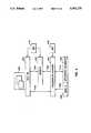
- FIG. 1illustrates one example of a cooperative processing environment, including workstations 102 for interacting with users, servers 104, and gateways 106.
- the servers 104 and gateways 106ar typically connected to the workstations 102 via a local area network (LAN) 108.
- the servers 104manage a database 110 of information.
- the gateways 106provide for communication 116 between the workstations 102 and remote systems, for example, host computer 112. Alternatively, the workstations 102 could be directly connected to the host computer 112.
- the host computer 112also manages a database 114 of information.
- Those skilled in the artwill readily recognize that any combination of workstations 102, servers 104, gateways 106, host computers 112, and communication links 116 could be substituted for the configuration shown.
- the preferred embodimentincludes a run-time execution architecture for executing applications on a plurality of computer hardware platforms.
- FIG. 2describes the preferred components of the run-time execution architecture services for user applications.
- the pre-programmed services of the run-time execution architectureinsulate the user applications from the detailed implementation of the presentation services for managing the user interface and the distribution services for managing message traffic.
- a client application 216 executing on a workstation 202is typically comprised of pre-programmed presentation services 218, application functions 220, and pre-programmed distribution services 222. In the preferred embodiment, only the design of the user-interface and the application functions 220 are user-specified.
- a server application 224 executing on the server 204is typically comprised of a pre-programmed server front-end 226, pre-programmed distribution services 228, application functions 230, and pre-programmed database access services 232. In the preferred embodiment, only the design of the database 210 and the application functions 230 are user-specified.
- a server application 238 executing on the host computer 212is typically comprised of a pre-programmed server front-end 240, pre-programmed distribution services 242, application functions 244, and pre-programmed database access services 246.
- pre-programmed server front-end 240pre-programmed distribution services 242, application functions 244, and pre-programmed database access services 246.
- application functions 244are user-specified.
- server applications 224 and 238 on the two platforms 204 and 212are functionally similar. Those skilled in the art will recognize that similar embodiments can be provided on any platform.
- a message manager 234 executing on the gateway 206 and a message manager 236 executing on the host computer 212are preferably pre-programmed modules.
- the message managers 234 and 236automatically route and transfer messages from an application on a first platform, for example, client application 216, to an application on a second platform, for example, server application 238.
- client application 216an application on a first platform
- server application 238an application on a second platform
- FIG. 3generally illustrates the preferred relationship of the different parts of the run-time execution architecture.
- Windows and other display itemsare created by using a Window Painter/Generator 304 to define and generate the user interface.
- the pre-programmed presentation services 302are comprised typically of Window Editing Services 306 and Window Widgets 308 that manage the windows and display items.
- the functions 310are client-resident functions which are typically specified by the user with the Structure Chart Editor 312 and generated by the user with the Code Generator 314 of the DESIGN/1® software system.
- the userscan write their own code in a standard language such as C, COBOL, etc., using standard programming tools 318, and embed this code in client applications.
- the functionsare comprised typically of process control and error handling routines 320.
- the pre-programmed distribution services 322are not changed by the user.
- the userdoes specify the configuration of hardware and software in the cooperative processing environment.
- the pre-programmed Message Manager 324uses this information to determine how to route message traffic.
- the functions 326are server-resident functions which are typically specified by the user with the Structure Chart Editor 328 and Code Generator 330 of the DESIGN/1® software system. In addition, the users can write their own code in a standard language such as C, COBOL, etc., using standard programming tools 334, and embed this code in the server applications.
- the functions 326are comprised typically of common business functions and error handling routines 336.
- the pre-programmed database access services 338manage databases created by users with a Data Modeler 340 of the DESIGN/1® software system.
- the userscan write their own database access services in a standard language such as C, COBOL, etc., using standard programming tools 334, and embed this code in the server applications.
- the Data Modeler 340defines and generates the database access services 338.
- the userscan write their own version of database access services 338 in a standard language such as C, COBOL, etc., using standard programming tools 334.
- the useralso has a repertoire of supporting tools including a Data Flow Diagrammer 344 from the DESIGN/1® software system, document editors 346, compilers 348, debuggers 350, copy member generators 354, etc.
- the specifications and designs output from all the development toolsare stored in a repository database 352.
- FIG. 4describes the preferred relationship of the pre-programmed presentation services 402 to the operating system 404 and the client application 406.
- the presentation services 402are a pre-programmed collection of services designed to provide a user-interface layer for the run-time execution architecture. The purpose of this layer is to reduce the amount of effort the programmer must put into dealing with the user-interface 408 and allow the programmer to concentrate more on the functions being implemented.
- Presentation services 402support a form-filling style of user-interface 408, as well as interfaces 408 that make use of direct object manipulation, graphics, images, and sound.
- the Window Editing Services (WES) of the presentation services 402provide a common validation and formatting service so that applications 406 only have to deal with valid data (e.g., a number field is numeric, a date field is valid, etc.), and do not have to write routines to format and verify certain types of data.
- WEScan transfer control to application functions in response to widget and window events 414, for example, such as the user entering a field. These events are defined by the user. Services to enable and disable end-user commands, to reflect the state of data entry or the application 406, are also provided since these are common user-interface features found in applications 406.
- WESalso provides a link to an on-line help manager and provides standard mouse, arrow, and cursor reporting services.
- a dialogue boxis a type of window used primarily for presenting or gathering information in a form-filling style.
- Widgetsare objects used by dialogue boxes to interact with a user, for example, entry fields, push buttons, check boxes, etc.
- Widgetsare self-contained objects which interact with the user in a predetermined manner and interact with their "owner window," usually the dialogue box, in a predetermined manner, for example, notifying the owner window of changes to the contents of a window, notifying the owner window of field exits, etc.
- widgets and dialogue boxesare the primary interaction mechanisms in the presentation services 402.
- a callback function 420is invoked at the widget level.
- a different callback function 420is invoked at the window level, for example, when all required fields are entered, and all widget contents are valid.
- widget and window level events 414there are two types of events that invoke callback functions 420 in applications 406: widget and window level events 414.
- Widget level eventsinclude field entry and exit, depressing or clicking of buttons, the selection of an item in a list box, the alteration of the contents of an entry field, the change in a field's status from valid to invalid, etc.
- Window level eventsinclude interfield validation requests wherein all widgets are invalid when a "major state" change has occurred, for example, a field exit with new data. Window level events can also occur when the window enters an invalid state, when a window is initialized, when a window is closed, or when the user requests a command.
- Window level eventsalso occur when the application registers 418 an interest in an object with the Shared Data Manager (discussed below) and a message is received from the Shared Data Manager. Window level events also occur when a message is received from the Message Manager (discussed below), whether unsolicited or as the result of an asynchronous message sent earlier to some server or other client.
- the presentation services of the preferred embodimentprovide the application with a memory model that represents the contents of the screen.
- FIG. 5illustrates a preferred use of this memory model.
- WESprovides a portion of memory 506 and 508, called WESMaps.
- WESfills the WESMap with the current data values, attributes, etc., for the widgets before calling an application callback function.
- the applicationcan change values, attributes, etc., directly in the WESMap with simple assignment statements.
- WESchecks the changes in the WESMap and updates the widgets accordingly.
- each WESMapthere is only one copy of each WESMap per window to prevent integrity problems due to concurrent updates caused by multiple threads.
- all other threads in a processare suspended when one thread requests the WESMap.
- the other threadsare released when the WESMap is released.
- semaphoresor other means to prevent concurrent updates to the WESMap.
- the preferred structure of the WESMapcomprises a window header, a group status, data values, and field control areas.
- the window headercontains window-level information that an application may manipulate, for example, the title of the window, the window size, etc.
- the group statusis an area intended as a status field for field groups defined within the window. This allows user commands to be tied dependently to a field group status so that when the field group is valid the command is enabled.
- Field valuesare the data items on the screen.
- the field control areais a control structure for each field in the window. This structure allows user applications to control the field display attributes, status, access rights, message id, field cursor, and other attributes which may be unique to a particular widget type.
- the display attributesare concerned with visual attributes.
- a value of -1 in this fieldindicates that the application is dealing directly with the widget and that WES should no do anything with it.
- the field statusis set every time the field data changes, and thus can be used as a change indicator. It also ensures that valid data is entered into the field.
- the field access rightsdetermine whether a field is enabled, disabled, hidden, etc.
- the field message idis the identifier of the message displayed in the message area when the user is in this field, for example, a brief explanation of the field, a warning message, etc.
- the field cursoris used by WES to indicate which field the cursor was in when the callback function was invoked, even though the field id is also passed as a parameter to the callback function.
- the applicationmay use this structure to identify and set the current field. If more than one field has this structure set, then the first one is made the current field.
- the WESMAPis represented by a copy member or include file, which those skilled in the art will recognize as a good technique for multiple functions or programs to use the same data structure.
- the copy member generator tool of the DESIGN/1® software systemgenerates the WESMap for each window.
- user commandsare preferably not tied to a particular type of widget, for example, push buttons, pull-down menus, etc.
- the presentation services 402allow an abstraction to be made so that the application 406 does not have to worry about the presentation format.
- the preferred embodimentprovides for a separation of the presentation from the meaning of the command.
- the application 406need not know what type of widget it is working with, instead, an application 406 simply refers to a command for a window and the presentation services 402 take care of the details. If a command needs to move from a menu to a button or vice versa, the application 406 does not have to be modified; only a WES control table 412 and a resource file 410 need to be updated. Similarly, as new widgets are developed, applications 406 can take advantage of them without changes to the application 406 itself.
- HideThere are some presentation services 402 functions used in dealing with user commands, including Hide, Show, Disable, Enable, and Attribute.
- the Hide functionis used if an application 406 does not want a user to know an option exists, for example, if the user security level is not appropriate.
- the Show commandis used where the command becomes available for some reason.
- the Disable commandcontinues to show the command on the screen but makes it unavailable for use. In most graphical user interfaces, this means that the push button or menu item corresponding to the command would be "greyed" to indicate that under the proper conditions, for example, all fields containing valid input, this command would be available.
- the Enable functionis used to indicate to the user that the command is available.
- the Attribute functionis used for attributes like active/inactive status, for example, when a check mark is used next to an active menu item.
- Maps to a repeating group of entry field referencesThe first entry in group is always a one byte ⁇ selected ⁇ flag
- Subsequent entriesrepresent the columns of each row.
- Each columncan be any data type supported by WES i.e., text, numeric, date, decode, etc.).
- the number of occurrences in a ⁇ master list ⁇is specified in the WES Control Table (WCT). This is not necessarily the number of occurrences visible in the listbox (e.g., 5 visible entries, but a master list of 50 entries).
- WCTWES Control Table
- WESprovides the scrolling features through master list.
- the applicationis notified via a callback if the user attempts to scroll above the top of list or beyond the end of list. This allows the application to refill the master list (i.e., to page up or down).
- FIG. 6is a simple example of a window.
- an application's view of this windowis a WESMap data area structured as follows:
- the WESMAPHEADER structurecontains the global fields WindowTitle, WindowSize, etc.
- the WindowGroupStatus fieldis a status field for the window-level group.
- the CustNumData field 602assumes the data type for the field is a two word integer.
- the CustNameData field 604has 32 bytes for an alphanumeric character string, plus an extra byte to null terminate the string (corresponding to the standard null terminated string in the C language; if generated in another language, for example COBOL, the null terminator would not be generated).
- the CreditLimitData field 606assumes the data type for the field is a floating point value.
- the FriendOfCEOData checkbox 608only needs a single byte to represent checked/unchecked.
- the BillingPrefData field 610uses an integer to represent the various values corresponding to the radio buttons.
- the ShippingPrefData field 612has 5 bytes for representing the length 4 character strings each radio button represents.
- the WESFLDCTL structurecontains control vectors for each field above.
- the members of the standard WESFLDCTL structureare: "Attr” --logical field attribute; “Status” --field status; “Rights” --field rights; "Msg” --message ID for this field; "Cursor” --cursor control.
- Some examples of the values for the various field control vectorsinclude:
- Attr--AT -- NORMALe.g., use default display attributes for the field
- AT -- SELECTEDe.g., highlighted
- AT -- ATTENTIONe.g., red
- AT -- NONDISPLAYe.g., hide field contents
- Status--STS -- WESVALIDe.g., valid WES data
- STS -- VALIDe.g., valid data
- STS -- INCOMPLETEe.g., incomplete
- STS -- INDETERMINATEe.g., status indeterminate due to asynchronous validation
- STS -- INVALIDe.g., field invalid
- Rights--RGT -- DISABLEDe.g., field disabled
- RGT -- PROTECTEDe.g., protected mode
- RGT -- STANDARDe.g., standard modes
- Cursor--CUR -- CURRENTe.g., current position
- CUR -- MAKECURRENTe.g., set cursor position
- the structure of the WCT and the packaging of the pre-programmed servicesmakes it possible to support additional control vectors in the field control structure that may be unique to a particular type of widget.
- BillingPrefDataLT -- BILLINGPREF -- HOME
- FriendOfCEOCursorCUR -- MAKECURRENT
- the complete field-control structurecan be referenced (i.e., for passing to a function) by using the field name without any qualifier (i.e., data, attr).
- qualifieri.e., data, attr.
- An example of passing the customer number field to a validation routineis:
- FIG. 7is an example of a simple listbox window.
- the window 702has 5 rows visible at any one time.
- An applicationmay have, for example, 50 rows defined in its "master list.”
- the Listbox nameis "CustList” (which is used for field control declarations).
- the memory model WESMapwould present to the application is:
- the CustListData structureis a selection indicator comprising 50 occurrences of the CustListSelData field containing a selection indicator, the CustNumData field containing the customer number, and the CustNameData field containing each row of a customer name, wherein each row comprises 32 characters.
- the CustListCtl structureis the control vector for the complete listbox.
- the CustListRowFldCtl structureis the control vector for the rows of the listbox.
- the CustListSelCtl fieldis the control vector for selection of a particular row.
- the CustNumCtl fieldis the control vector for each entry in the "CustNum” column.
- the CustNameCtl structureis the control vector for each entry in the "CustName” column.
- FIGS. 8A and 8Bdescribe the data structures used by the presentation services in the preferred embodiment.
- a list of all defined windows available to the systemis maintained in a Window Definition Table 818.
- Each window 804 and 806is identified on a screen 802 by a window handle, "927" and "1115" respectively.
- a list of all active windows and an "instance” number associated therewithis maintained in an Active Instance Table 816.
- a list of window handles and the associated pointers 810 and 814 to the specific "instance data" associated with a windowis maintained in an Instance Table 812.
- a data pointer 810is shown, which pointer is associated with window 804 whose handle is "927".
- the data pointer 810points at the Window Instance Structure 808.
- the Window Instance Structure 808is the structure WES creates and associates with a window. This structure contains all the data required by WES for handling and dispatching events.
- the Window Instance Structure 808is comprised of pointers to an Application WESMap 826, a Master WESMap 824, a WES Control Table 820, a Command Table 822, a Widget Dispatch Table 832, a Window Dispatch Table 830, a Window Context Data area 828, a Business Function Context Data area 836, an Execution Architecture Info area 838, and an Error Handler Parameter Block 840.
- the Application WESMap 902is a memory area passed to application program, and includes header information, widget data and widget control attributes.
- the Master WESMap 904is a second copy of WESMap used by WES to detect changes made by application.
- the WES Control Table 906is a list of widget, widget types and associated data.
- the Command Table 908is a list of user commands and associated data.
- the Widget Dispatch Table 910is a list of widgets, events and callback routines.
- the Window Dispatch Table 912is a list of windows and callback routines.
- the Window Context Data 914contains data unique to each instance of a window.
- the String-Constants Pointer 916is a pointer to strings used for widget values.
- the Business Function Context Data 918contains data shared across all windows of the same Business function.
- the Execution Architecture Information Area Pointer 920is a pointer to Execution Architecture specific data.
- the Error Handler Parameter Block Pointer 922is a pointer to common error handler interface data.
- a WES Control Table (WCT) 820is described in FIGS. 10A, 10B, and 10C, and contains the following fields.
- the Window ID 1002identifies the class of the window.
- the Instance ID 1004is used to distinguish between multiple instances within a class of window.
- the Number Of Widgets 1006is the number of widget definitions associated with the window.
- the Number Of Fields 1008is the number of fields in WESMap.
- the Size Of WESMap 1010is the size of WESMap in bites.
- the Current Field 1012identifies the field where the cursor is position.
- the Mouse Pointer Cursor 1014is the shape of pointer when it is positioned in this window.
- the Modality 1016is the modality of this window (i.e., application modal, system modal, or modeless).
- the Language Type 1018identifies the programming language used to write the application.
- the Window Help Link 1020identifies the window-level "help" text.
- the Array Of Widget Definition Structures 1022is described in FIG. 10B and contains the following fields.
- the Widget Type 1024identifies a type of widget (e.g., text field, date field, radio button, etc.).
- the WESMap Offset 1026is the offset for the widget data value.
- the WESMap Length 1028is the length of the widget data value.
- the WESMap Data Type 1030is the internal format of the widget data value (e.g., floating point, character, etc.).
- the Offset Of Field Control Data In WESMap 1032identifies the location of the field control structure.
- the Help Link 1034identifies the "help" text for the widget.
- the structures used for the Widget Specific Information 1036are described in FIG. 10C and contain the following fields.
- the Radio Button Structure Definition 1038contains the following fields.
- the Parent Radio Group Widget ID 1046identifies the group of which the button is a member.
- the Radio Button Value Constant 1048identifies the value of the radio button.
- the Radio Group Structure Definition 1038contains the following fields.
- the Widget ID Of First Radio Button 1050identifies the first radio button in the group.
- the Widget ID Of Last Radio Button 1052identifies the last radio button in the group.
- the Listbox Structure Definition 1042contains the following fields.
- the Required Field Flag 1054indicates that a selection must be made.
- the Widget ID Of First Column 1056identifies the widget for the first column in the listbox.
- the Number of Rows In Master List Array 1058is the predefined size of the memory allocated for the list.
- the Number Of Columns In Listbox 1060is the predefined number of columns in the listbox displayed on the screen.
- the Multiple Selection Flag 1062indicates whether multiple rows can be selected.
- the Listbox Column Definition 1044contains the Parent ID 1064 which identifies the widget that owns the column of the listbox.
- a Command Table 822is described in FIG. 11, and contains the following fields.
- the Number of Commands 1002identifies the number of entries in the table.
- the Array Of Command Definitions Structures 1004contains the following fields.
- the Command ID 1006uniquely identifies the command.
- the Widget ID 1008identifies the widget associated with the command.
- the Widget Type 1010identifies the type of widget (e.g., push button, menu item, etc.).
- the Preemptive Command Flag 1012indicates whether the command is always enabled or is dependent on the status of the window or group of fields.
- the Command Rights 1014are the current rights and availability of command (i.e., enabled, hidden, etc).
- the Command Attribute 1016identifies the current command attributes.
- the Help-Link 1018identifies the "help" text for the command.
- a Widget Dispatch Table 832is described in FIG. 12, and contains the following fields.
- the Number of Entries 1202gives the number of entries in the table.
- the Widget Dispatch Structure Definition 1204contains the following fields.
- the Widget ID 1206identifies the widget.
- the Event ID 1208identifies the event that occurs with the widget (i.e., field exit, field change, etc).
- the Callback Function Pointer 1210identifies the function that should be invoked when the event occurs for the widget.
- a Window Dispatch Table 830is described in FIG. 13, and contains the following fields.
- the Number of Entries In Table 1302is the number of entries in the dispatch table.
- the Window Dispatch Structure Definition 1304contains the following fields.
- the Event ID 1306identifies the event that occurs (i.e., pre-display, interfield validation, etc).
- the Callback Function Pointer 1308identifies the function that should be invoked when the event occurs for the window.
- a Window Definition Table 818is described in FIG. 14, and contains the following fields.
- the Number Of Windows 1402is the number of window types in the client application.
- the Window Information Structure Definition 1404contains the following fields.
- the Version 1406identifies the version of the data structure.
- the Window ID 1408is the Presentation Services window ID.
- the Window Class Name 1410is the window class for non-WES windows.
- the Window Type 1412may be WES, native Presentation Manager, or some other type.
- the Default Modality 1414indicates whether the window is application modal, modeless or system modal.
- the Create At Startup 1416is a flag indicating a window should be created when the application first starts.
- the Create Options 1418can create a window as an icon, hidden, maximized, etc.
- the Dialogue Resource ID 1420identifies the resource to be used to display the window.
- the Menu ID 1422is the menu identifier to use for the window.
- the Icon ID 1424describes the bit mapped icon graphic to use for the window when shrunk to icon size.
- the Widget Dispatch Table 1426is a pointer to the Widget Dispatch Table (see FIG. 12).
- the Window Dispatch Table 1428is a pointer to the Window Dispatch Table (see Figure 13).
- the Class Style 1430includes the Class Style registration options for native Presentation Manager windows.
- the PM Create Options 1432include the Default Frame creation options for native Presentation Manager windows.
- the Distribution Services 322are preferably pre-programmed modules and processes that provide for the automatic routing and transferring of messages based on the function or service being requested. Alternatively, the Distribution Services 322 provide for the automatic routing and transferring of messages based on a direct address. The Distribution Services 322 determine the location of the service, route the request to that location, handle exceptions (such as time-outs, routing errors, transmission errors, and other abnormal conditions), and return an optional reply from the service to the client-requester.
- exceptionssuch as time-outs, routing errors, transmission errors, and other abnormal conditions
- the Distribution Services modules 222, 228, and 242, and Message Manager processes 234 and 236,reside on all supported hardware platforms 202, 204, 206 and 212. This means that the Distribution Services 322, in the preferred embodiment, reside on all hardware platforms running OS/2 and CICS.
- the Distribution Services 322are functionally divided into four (4) layers: (1) Transmission Services (TS); (2) Message Services (MS) and (3) Guaranteed Delivery (GD). Each of the layers is described in more detail below.
- FIG. 15describes a Message Header 1500 that is used by the Distribution Services 322 when transferring messages.
- the Message Headerprecedes 1500 all data transmitted between nodes.
- the Message Header 1500is preferably comprised of the following fields.
- the VERSION field 1502indicates which version of the software generated the Message Header 1500, thereby permitting revisions as required.
- the SOURCE-ADDRESS field 1504indicates the routing location of the sender of this message. Within the SOURCE-ADDRESS field 1504, the SOURCE-SERVICE-ID field 1506 indicates the service type of the sender, the SOURCE-NODE field 1514 indicates the node that the message came from, and the SOURCE-PORT field 1524 indicates the local source address of the message (i.e., a queue, a unique process identifier, etc).
- the SOURCE-SERVICE-NAME field 1510identifies the name of the sending service
- the SOURCE-SERVICE-VERSION field 1510identifies the version of the service
- the SOURCE-SERVICE-INSTANCE field 1512identifies a particular instance of the service.
- the SOURCE-NODE field 1514the SOURCE-MAJOR-NODE-NAME field 1516 and the SOURCE-MINOR-NODE-NAME field 1522 identify the node where the service resides.
- the SOURCE-NODE-AREA field 1518identifies the area where the node resides and the SOURCE-NODE-NUM field 1520 identifies the unique node number within the particular area.
- the DEST-ADDRESS field 1526indicates the routing location of the receiver of this message.
- the DEST-SERVICE-ID field 1528indicates the service type requested
- the DEST-NODE field 1536indicates the node that the message is destined for
- the DEST-PORT field 1546indicates the local destination address of the message (i.e., a queue, a unique process identifier, etc).
- the DEST-SERVICE-NAME field 1530identifies the name of the requested service
- the DEST-SERVICE-VERSION field 1532identifies the version of the service
- the DEST-SERVICE-INSTANCE field 1534identifies a particular instance of the service.
- the DEST-MAJOR-NODE-NAME field 1538 and the DEST-MINOR-NODE-NAME field 1544identify the node where the service resides.
- the DEST-NODE-AREA field 1540identifies the area where the node resides and the DEST-NODE-NUM field 1542 identifies the unique node number within the particular area.
- the MSG-IDENTIFIER field 1548is a unique identifier for the message being sent, generated by the source-side message services.
- the ENVIRONMENT field 1550indicates the operating environment of the message.
- the DATA-LENGTH field 1552indicates the length of the data area that follows the Message Header 1500.
- the STATUS field 1554is used between two platforms to indicate the internal return code from an operation.
- the ROUTING-CONTROL field 1556provides control over the sending and re-sending of messages between nodes.
- the MSG-TYPE field 1558indicates whether this message is a request or a reply.
- the PROCESSING-TYPE field 1560indicates whether a reply is requested, no reply is requested, or guaranteed delivery is to be used.
- the Transmission Services (TS) layerpreferably uses vendor-provided communications access methods, such as LU 6.2 and the OS/2 LAN Manager, to provide network-wide connectivity.
- the functionality provided by the TS layerpreferably includes:
- the Message Services (MS) layerpreferably works with the Transmission Services to implement the client/server model.
- the functionality provided by the MS layerpreferably includes:
- MSsends messages from a source node to the peer MS component residing within a destination node.
- source and destination nodesare adjacent and hence no intermediary MS nodes are involved.
- intermediary MS componentsi.e., Message Managers residing on one or more intermediary nodes.
- MSBecause of the intermediary routing function, for each message received MS compares the DEST-ADDRESS 1526 of the Message Header 1500 in FIG. 15 with that of its own node, and if they match, places the message on the client or server application queue. Otherwise, MS routes the message to the destination MS.
- Each workstation nodeobtains their addresses their respective MS Configuration Files. Host nodes obtain their addresses from their respective MS Configuration Files.
- An alternative embodimentcould use a gateway resident MS Address Server to dynamically assign an address to each workstation node during MS connection establishment.
- MSwill route replies to request messages if so requested, but typically the application is not blocked while the reply is outstanding. Matching of replies to requests allows MS to deliver a reply to the proper requestor and to filter out replies destined for applications that have already been released from their wait for the reply through the operation of a timeout.
- Timeout intervalsare assigned to each MS request message that expects a reply. If the timeout interval expires before a corresponding reply is received, MS calls the error logging subsystem to log the error and builds a reply message containing a REQUEST-TIMEOUT code in a Status field of a Parameter Block which is returned to the requesting application. If the reply appears subsequent to these actions, an error will be logged and the reply will be discarded.
- MStypically determines whether a given service request can be satisfied at the local node (i.e., a local server) or must be shipped to some remote node for servicing (i.e., a remote server).
- Local server requestsbypass TS and are sent directly to the appropriate server.
- MStranslates the service identifier, i.e., DEST-SERVICE-ID 1528 of the Message Header 1500 in FIG. 15, received from the application to the correct physical address, i.e., DEST-NODE 1536 of the Message Header 1500 in the FIG. 15. All of these fields need not be specified. The address is then mapped to a virtual circuit and the proper TS line handler. For applications needing a direct addressing capability, a DEST-NODE field 1536 of the Message Header 1500 in FIG. 15 can be specified in place of the DEST-SERVICE-ID 1528.
- MSdetermines the local server configuration and availability. This information is then sent in an MS control message to all other (remote) MS nodes in the network. Each remote MS that receives this message uses it to update the server records in its own Node Availability Table, and replies with information concerning the current availability of its own local servers; this information is used by the originating MS to update its Node Availability Table. After this exchange of control messages, MS initialization is complete. These tables can also be configured statically prior to startup if desired. The MS must also monitor the current availability of all local servers and notify all other MS nodes about status changes within its node.
- MSis typically responsible for translating incoming data into the format appropriate for the local hardware.
- an applicationrequests that MS send a message, it passes a Translation Control Block to MS, which describes the format of the fields in the message.
- MS on the sending node and MS and the receiving nodework together to translate the message.
- the Translation Control Blockis generated by a tool in the DESIGN/1® software system. Examples of format translation include ASCII to EBCDIC and inverted byte binary to non-inverted byte binary.
- MS nodesare characterized as:
- Gateway(Gateway MS).
- Workstation MSmaintains a very limited Routing Table in the preferred embodiment. Following node initialization, a Workstation Routing Table typically contains one entry for each server residing on that node, and one entry for the gateway-resident address server.
- Workstation MSWhen a request arrives for a service not represented in the workstation routing table, Workstation MS generates and sends an address resolution request to the gateway-resident address server. The returned address information updates the Workstation Routing Table and the original request is now sent.
- Gateway MSreceives service availability information from:
- Gateway MSexchanges LAN-based service availability information with all Host MS's and Gateway MS's in the network. Rather than propagating Host MS and Workstation MS service availability information to locally attached Workstation MS's, preferably the Gateway MS makes the information available through a gateway-resident address server.
- a serviceis characterized by a set of service attributes. These attributes are kept and maintained by the Message Services. They are obtained from service descriptor entries residing either in the local MS configuration file (locally resident services), or from service descriptor entries passed from MM to MM via through service resource exchange messages. In the preferred embodiment, attributes may be classified as either permanent or transient.
- the instance opcode and instance operandWhen qualified by a service name, the instance opcode and instance operand identify a specific server process. This process provides the service indicated by server name.
- a servicemay have either local, global, or LAN scope. Services with local scope are known and available only to clients residing on the same node as the service. Thus, MS does not exchange information regarding these services with remote MS nodes. Globally scoped services, by far the more common, are available to clients residing on any node of the network. A LAN scoped service is available only to nodes residing on the same LAN as the service.
- transient attributes in the preferred embodimenttend to vary ⁇ frequently ⁇ over time, some changing more often than others.
- the MSpermits a application to specify a DEST-SERVICE-VERSION field 1532 of the Message Header 1500 in FIG. 15. If the application exercises this option, MS will send the message only to a service with a matching version. If no such service exists, an error code will be returned to the application.
- the Guaranteed Delivery service in the preferred embodimentprovides guaranteed store-and-forward message delivery between two applications.
- the guaranteed in ⁇ Guaranteed Delivery ⁇refers to the use of vendor-supplied transaction services to provide:
- the above vendor-provided servicesprovide, in the preferred embodiment, the functionality and degree of reliability defined for the Guaranteed Delivery service.
- the Server Front End(SFE) is a pre-programmed service which manages server applications in the preferred embodiment. Its purpose is to make it easier for programmers to build applications and to standardize programming interfaces.
- An embodiment of the Server Front Endexists on all platforms which can run the described run-time execution architecture. The Server Front End is customized on each of these platforms to run properly on that platform. By being so built, it enables application functions to be similar or identical on all platforms, thereby enabling portability of application functions between platforms.
- the Server Front Endpreferably performs the services of:
- Receiving messages from the Distribution Services, which were sent by another applicationcould be on any computer which can communicate with the SFE.
- routing the reply message (if any) from the application to the sender of the original request messageUpon completion of the application function, routing the reply message (if any) from the application to the sender of the original request message.
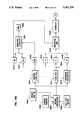
- FIGS. 16A and 16Billustrate a preferred relationship between the design tools 1602, 1604, and 1606, the repository 1608, the construction tools 1610, 1612, 1614, 1630, 1632, 1634, and 1644, and the user application 1646.
- the preferred embodimentprovides a plurality of design tools 1602, 1604, and 1606 for building applications for the run-time execution architecture.
- design toolsinclude the standard tools familiar to those skilled in the art, for example, a Structure Chart Editor 1604, a General Document Editor 1606, etc.
- the functions performed by the design toolswere discussed in more detail hereinbefore in conjunction with FIG. 3. Further information is also available in the FOUNDATION® DESIGN/1® manual.
- the definitions created by these design toolsare stored in a repository 1608.
- the repository 1608provides means for categorizing, indexing, and cross-referencing the specifications for user applications.
- the repository 1608supports the informational entities necessary to define the operations to be performed by the Presentation Services, Distribution Services, and Database Access Services.
- a Window Painter 1602defines user interfaces in windowing systems, so that the applications may take advantage of windowing features comprising entry fields, static text, group boxes, radio buttons, check boxes, list boxes, lines, icons, and rectangles.
- the Window Painter 1602stores these user interface definitions in the repository 1608.
- FIG. 17describes the preferred structure of a Window Definition entity 1700.
- the Window Painter 1602creates this entity 1700 to store window and dialogue box attributes.
- the Window Definition entity 1700is comprised of the fields Window Name 1702, Window Class Name 1704, Default Modality 1706, Create On Startup Flag 1708, Menu Indicator 1707, Icon Name 1712, Title 1714, Default Origin 1716, Size 1718, PM Style Bits 1720, Frame Creation Flags 1722, and Initial Focus Widget ID 1724.
- FIG. 18describes the preferred structure of a Window - Menu Relationship entity 1800.
- the Window Painter 1602create this entity 1800 to establish the relationship between a window and its pull-down menus or menu items.
- the Window - Menu Relationship entity 1800is comprised of the fields of Window Name 1802, Sequence 1804, Menu Type (pull-down or menu item) 1806, and the Name Of The Pull-Down Menu Or Menu Item 1808.
- FIG. 19describes the preferred structure of a Window - Widget Relationship entity 1900.
- the Window Painter 1602creates this entity 1900 to establish a relationship between a window and its widgets.
- the Window - Widget Relationship entity 1900is comprised of the fields of Window Name 1902, Widget Name 1902, Widget Origin 1906, Widget Size Override 1908, Widget PM Style Attributes Override 1910, Default Attribute, Status, and State 1912, Default Color and Font 1914, Default Message ID 1916, On-Line Help Link 1918, Widget Specific Attributes and Overrides 1920, and C Variable Name Override 1922.
- FIG. 20describes the preferred structure of a Window - Widget - Callback Relationship entity 2000.
- the Window Painter 1602creates this entity 2000 to establish a tie between a callback function and widget-level events for a specific window.
- the Window - Widget - Callback Relationship entity 2000is comprised of the fields of Window Name 2002, Widget Name 2004, Widget Event ID 2006, and Callback Function Pointer 2008.
- FIG. 21describes the preferred structure of a Window - Callback Relationship entity 2100.
- the Window Painter 1602creates this entity 2100 to establish a tie between a callback function and a widget-level event.
- the Window - Callback Relationship entity 2100is comprised of the fields of Window Name 2102, Window Event ID 2104, and Callback Function Pointer 2106.
- FIG. 22describes the preferred structure of a Listbox Definition entity 2200.
- the Window Painter 1602creates this entity 2200 to define a listbox and its default attributes.
- the Listbox Definition entity 2200is comprised of the fields of Listbox Name 2202, Default Size 2204, Default PM Style Attributes 2206, Multiple Selection Flag 2208, Required Field Flag 2210, the Number Of Rows in the "master list” array 2212, and a Default C Variable Name 2214.
- FIG. 23describes the preferred structure of a Listbox - Element Relationship entity 2300.
- the Window Painter 1602creates this entity 2300 to establish a tie between the listbox and the element definitions for its columns.
- the Listbox - Element Relationship entity 2300is comprised of the fields of Listbox Name 2302 and Element Name 2304.
- FIG. 24describes the preferred structure of a Push-Button Definition entity 2400.
- the Window Painter 1602creates this entity 2400 to define a push-button and is similar to a function key definition.
- the Push-Button Definition entity 2400is comprised of the fields of Push-Button Name 2402, Default Size 2404, Default PM Style Attributes 2406, Push-Button Text 2408, Mnemonic Character 2410, Function/Event ID 2412, Preemptive Function Flag 2414, and Default Function State and Attribute 2416.
- FIG. 25describes the preferred structure of a Menu Definition entity 2500.
- the Window Painter 1602creates this entity 2500 to define a menu item.
- the Menu Definition entity 2500is comprised of the fields of Menu Name 2502, Default PM Style Attributes 2504, Menu Text 2506, Mnemonic Character 2508, Command/Event ID 2510, Preemptive Command Flag 2512, Default Command State and Attribute 2514, Accelerator Character 2516, and Parent Menu Name 2518.
- FIG. 26describes the preferred structure of an Icon Definition entity 2600.
- the Window Painter 1602creates this entity 2600 to define a icon.
- the Icon Definition entity 2608is comprised of the fields of Icon Type 2602, Resource ID 2604, Filename 2606, and Loading Option 2610.
- the Icon Type field 2602identifies the icon.
- the Resource ID field 2604is a numeric identifier for the icon.
- the Filename field 2606identifies the physical file containing the bit mapped graphic for display.
- the Loading Option field 2608specifies dynamic or static linking.
- the Window Painter 1602is used to define, during the design phase, the window layout, window attributes, literal attributes, widget attributes and callback functions for user applications.
- the preferred embodimentprovides Construction Tools 1610, 1612, 1614, 1630, 1632, 1634 and 1644 for generating code shells, executable object modules, and tables for the client and server applications 1646.
- a Window Generator 1610reads window and widget definitions, and other entities, (previously described in FIGS. 17 through 26) from the repository 1608 and generates a number of tables for use by the pre-programmed presentation services, including a Dialogue file 1618, a WES Control Table 1620 (previously described in FIGS. 10A, 10B, and 10C), and a WESMap, Window Dispatch Table (previously described in FIG. 13), Widget Dispatch Table (previously described in FIG. 12), and a Window Definition Table entry (previously described in FIG. 14), all of which are identified by reference number 1622.
- the Window Generator 1610generates tables in a format specific to each targeted platform, whereas the Window Painter 1602 creates definitions for the repository 1608 independent of the targeted platform.
- the Dialogue file 1618is preferably a free-form text file containing English-like descriptions of the windows. The descriptions are, in fact, a command language used to define the window.
- the Dialogue file 1618contains the OS/2 Presentation Manager resource file definition and control information for each window.
- the Dialogue file 1618contains formatting information for the window as a whole and for each of the items painted on the window, including position, size, default behavior, font information, and other formatting data.
- the command languageis comprised of mnemonics for defining the window title, window id, x and y coordinates on the screen for initial placement, width and height of the window, and other attributes. Those skilled in the art will recognize that other means of generating such resource files could also be used.
- the Dialogue file 1618is used to generate a resource file 1636, which was described hereinbefore by reference number 410 in FIG. 4.
- resource filesare well known to those knowledgeable about the IBM OS/2 Presentation Manager operating system and will not be discussed further herein.
- other environmentsmay use other techniques in place of the resource file 1636.
- the preferred embodimentwill support analogous techniques appropriate for each particular environment.
- the Window Generator 1610uses the Window Definition entity 1700 of FIG. 17 to create the corresponding fields of the Window Definition Table 1400 of FIG. 14.
- the Window Definition entity 1700 of FIG. 17provides the Window Definition Table 1400 of FIG. 14 with the fields of Window Name 1702 (Window ID 1408 of FIG. 14), Window Class Name 1704 (Window Class Name 1410 of FIG. 14), Default Modality 1706 (Modality 1414 of FIG. 14), Create On Startup Flag 1708 (Create At Startup 1416), Menu Indicator 1710 (Menu ID 1422 of FIG. 14), and Icon Name 1712 (Icon ID 1424 of FIG. 14).
- the remaining fields, Title 1714, Default Origin 1716, Size, 1718, PM Style Bits 1720, and Frame Creation Flags 1722,are used to build commands in the dialogue file 1618 of FIG. 16A.
- the Window Generator 1610uses the Window - Menu Relationship entity 1800 of FIG. 18 to create the corresponding fields of the Command Table 1100 of FIG. 11.
- the Window - Menu Relationship entity 1800provides the fields of Sequence 1804 (Widget ID 1108 of FIG. 11) and Menu Type 1086 (Widget Type 1110 of FIG. 11).
- the remaining fields, Window Name 1802 and Name Of Pull Down Menu Or Menu Item 1808,are used to build commands in the dialogu file 1618 of FIG. 16A.
- the Window Generator 1610uses the Window - Widget Relationship entity 1900 of FIG. 19 to create the corresponding fields of the WES Control Table 1000 of FIGS. 10A, 10B, and 10C.
- the Window - Widget Relationship entity 1900provides the fields of Window Name 1902 (Window ID 1002 of FIG. 10A), Widget Name 1904 (Widget Type 1024 of FIG. 10B), and On-Line Help Link 1918 (Help Link 1034 of FIG. 10B).
- Widget Origin 1906Widget Size Override 1908
- Widget PM Style Attributes Override 1910Default Attribute, Status, and State 1912
- Default Color And Font Information 1914Default Message ID 1916
- Widget Specific Attributes And Overrides 1920are used to build commands in the dialogue file 1618 of FIG. 16A.
- the C Variable Name Override 1922is used within a WESMap to identify a data location therein.
- the Window Generator 1610uses the Window - Widget - Callback Relationship entity 2000 of FIG. 20 to create the corresponding fields of the Widget Dispatch Table 1200 of FIG. 12, which is pointed to by the Window Definition Table 1400 of FIG. 14.
- the Window - Widget - Callback Relationship entity 2000provides the fields of Widget Name 2004 (Widget ID 1206 of FIG. 12), Widget Event ID 2006 (Event ID 1208 of FIG. 12), and Callback Function Pointer 2008 (Callback Function Pointer 1210 of FIG. 12)
- the Window Name 2002 of the Window - Widget - Callback Relationship entity 2000provides the link between a Window Definition Table 1400 of FIG. 14 and the Widget Dispatch Table 1200 of FIG. 12.
- the Window Generator 1610uses the Window - Callback Relationship entity 2100 of FIG. 21 to create the corresponding fields of the Window Dispatch Table 1300 of FIG. 13, which is pointed to by the Window Definition Table 1400 of FIG. 14.
- the Window - Callback Relationship entity 2100provides the fields of Window Event ID 2104 (Event ID 1306 of FIG. 13) and Callback Function Pointer 2106 (Callback Function Pointer 1308 of FIG. 13).
- the Window Name 2102 of the Window - Callback Relationship entity 2100provides the link between a Window Definition Table 1400 of FIG. 14 and the Window Dispatch Table 1300 of FIG. 13.
- the Window Generator 1610uses the Listbox Definition entity 2200 of FIG. 22 to create the corresponding fields of the WES Control Table 1000 of FIGS. 10A, 10B, and 10C.
- the Listbox Definition entity 2200provides the fields of Listbox Name 2202 (Widget Type 1024 of FIG. 10B), Default Size 2204 (WESMap Length 1028 of FIG. 10A), Multiple Selection Flag 2208 (Multiple Selection Flag 1062 of FIG. 10C), Required Field Flag 2210 (Required Field Flag 1054 of FIG. 10C), and the Number Of Rows In Master List Array 2212 (Number Of Rows In Master List Array 1058 of FIG. 10C).
- the remaining fields, Default Size 2204 and Default PM Style Attributes 2206are used to build commands in the dialogue file 1618 of FIG. 16A.
- the Default C Variable Name 2214is used within a WESMap to identify a data location therein.
- the Window Generator 1610uses the Listbox - Element Relationship entity 2300 of FIG. 23 to create corresponding fields in the dialogue file 1618 of FIG. 16A.
- the Listbox Name 2302provides a link to the Listbox Definition entity 2200 of FIG. 22.
- the Element Name 2304provides a name for the entry in the dialogue file 1618 of FIG. 16A.
- the Window Generator 1610uses the Push-Button Definition entity 2400 of FIG. 24 to create the corresponding fields of the Command Table 1100 of FIG. 11.
- the Push-Button Definition entity 2400provides the fields of Push-Button Name 2402 (Widget ID 1108 of FIG. 11), Preemptive Command Flag 2414 (Preemptive Command Flag 1112 of FIG. 11), and Default Command State and Attribute 2416 (Command Attribute 1116 of FIG. 11).
- the remaining fields, Default Size 2404, Default PM Style Attributes 2406, Push-Button Text 2408, and Mnemonic Character 2410are used to build commands in the dialogue file 1618 of FIG. 16A.
- the Window Generator 1610uses the Menu Definition entity 2500 of FIG. 25 to create the corresponding fields of the Command Table 1000 of FIG. 11.
- the Menu Definition entity 2500provides the fields of Menu Name 2502 (Widget ID 1108 of FIG. 11), Command/Event ID 2510 (Command Id 1106 of FIG. 11), Preemptive Command Flag 2512 (Preemptive Command Flag 1112 of FIG. 11), and Default Command State and Attribute 2514 (Command Attribute 1116 of FIG. 11).
- the Menu Parent Name 2518provides link for the different levels of menus, sub-menus, etc.
- the Window Generator 1610uses the Icon Definition entity 2800 of FIG. 28 to create the corresponding fields of the Window Definition Table 1400 of FIG. 14.
- the Icon Definition entity 2800provides the fields of Icon Type 2802 (Icon ID 1424 of FIG. 14) and Resource ID 2804 (Dialogue Resource ID 1420 of FIG. 14).
- the remaining fields, Filename 2806 and Loading Option 2808,are used to build commands in the dialogue file 1618 of FIG. 16A.
- a Code Generator 1612uses the structure charts stored in the repository 1608 to generate the functions found in the application callback source code 1624.
- usersmay also manually program functions into the application callback source code at point 1626 in FIG. 16A.
- Functionsare typically designed using the FOUNDATION® Structure Chart Editor. Once the user has completed the Structure Charts for the required functions, the native source code for these functions can be generated.
- the process of generating native source codeconsists of reading the Structure Chart definitions from the repository 1608, then translating those definitions using a Spec-Language Translator.
- the Translatorfunctions logically within the Code Generator 1612 according to FIG. 16A, but in the preferred embodiment actually is a physically distinct program.
- the Spec-Language Translatorgenerates a standard language equivalent, e.g., C, COBOL, etc. Thus, it is the responsibility of the Code Generator 1612 to build the file used to create the actual executable code.
- the output file of the Code Generator 1612is the source file for the user application.
- usersmay enter native source code manually.
- a standard programming languagesuch as COBOL, C, etc.
- usersthus eliminate the need for the Spec-Language Translator.
- the specifications for data structuresare created by the FOUNDATION® Dataflow Diagrammer and then stored in the repository 1608.
- the specifications for data structurescan be created using a general document editor without diagramming.
- a Copybook Generator 1614reads data structure specifications and other entities from the repository 1608 and generates language-specific copybooks 1628. These copybooks 1628 contain the source code structures for using the Message Header, data structures, etc.
- a Backbone Generator 1632combines the Window Dispatch Table, Widget Dispatch Table, Window Definition Table and a WESMap structure, together referred to as 1622, the application callback source code 1624, and the copybooks 1628 to create the command files used to create the actual executable code.
- the output files of Backbone Generatorare the source file with include references and a ⁇ make ⁇ file (on workstations and other platforms where they are used) for compiling each module of the program, which is input to the Compiler 1634 and an application resource file 1616.
- a standard Compiler 1634takes the output file from the Backbone Generator and creates the program object code 1638 for the user application.
- a Resource Compiler 1630uses the application resource file 1616 and dialogue file 1618 to create an Resource File 1636.
- the application resource file 1616indicates which window definitions should be extracted from the dialogue file 1618 for inclusion in the Resource File 1636.
- the dialogue file 1618contains formatting information for the window as a whole and for each of the items painted on the window. As described above, formatting information includes position, size, default behavior, font information, and other formatting data.
- the Resource Compiler 1630is used only for applications which have a user interface, i.e., a client application. For some applications which do not have a user interface, e.g., server applications, the Resource Compiler 1630 may not be required.
- a standard Linker 1644joins the program object 1638, a shell object 1640, and an application library object 1642 into an application executable object module 1646.
- the shell object 1640is a standard object module containing the "main" procedure of the application and global data pointers.
- the application library object 1642is a standard object module containing commonly-used functions.
- the executable object module 1646includes the modules or routines to access them described hereinbefore in FIG. 3, including the pre-programmed presentation services (if a client application), the user-specified functions, the pre-programmed distribution services, the pre-programmed server-front end (if a server application), and the database access services (if a server application).
- FIGS. 27, 28, and 29shows the preferred structure of the user applications as they are generated by the construction tools.
- FIG. 27shows the preferred run-time structure for a client application 2702.
- the client application 2702is comprised of headers 2704, data 2706, initialization 2708, processing loop 2710, callback functions 2712, common functions 2714, error handlers 2716, and cleanup 2718.
- the headers 2704are declarations of constants and data structures. These declarations come primarily from the copybooks.
- the data 2706is working storage variables.
- the initialization 2708is comprised of setup routines.
- the processing loop 2710is a loop which performs two functions: (1) retrieving messages from the Distribution Services, and (2) dispatching messages based on the function requested.
- the callback functions 2712are the functions called by WES or by the run-time execution architecture in response to events not originating from the user interface.
- the common functions 2714are functions not directly called by the user interface, i.e., WES.
- the error handlers 2716are functions which perform error processing.
- the cleanup 2718performs various cleanup routines pending the termination of a client 2702.
- FIG. 28describes the preferred run-time structure 2802 for an OS/2 server application.
- the run-time structure 2802comprises headers 2804, data 2806, initialization 2808, processing loop 2809, request handlers 2810, common functions 2812, error handlers 2814, and cleanup 2816. These functions are similar to those described in the client run-time structure 2702 of FIG. 27. The differences are in the processing loop 2810, request handlers 2812, and common functions 2814.
- the processing loop 2810reads a request queue and invokes a procedure based on the type of request received.
- the request handlers 2812are the functions called by the processing loop 2810 used on the type of request.
- the common functions 2814are functions not directly called by the processing loop 2810.
- FIG. 29describes the preferred run-time structure 2902 for a CICS server application.
- the run-time structure 2902includes headers 2904, data 2906, initialization 2908, process requests 2910, request handlers 2912, common functions 2914, error handlers 2916, and cleanup 2918.
- This run-time structure 2902is similar in function to the OS/2 run-time structure 2702 described in FIG. 27.
- FIG. 30describes a Shared Data Manager (SDM) 3002 facility, which in the preferred embodiment provides applications 3004 in the execution architecture with an ability to access a common pool of information.
- SDM 3002stores information in the form of ⁇ objects ⁇ classified by a business function, class and instance.
- applications 3004can also register interest in them so that if an object data is updated or deleted, the interested applications are notified of the change.
- SDM described hereinis just one possible implementation, and those skilled in the art will readily recognize that other implementations could be used.
- the SDM 3002is a ⁇ server ⁇ application.
- Objects and the associated dataare maintained internally in the SDM 3002 in various tables and linked lists. These tables and liked lists preferably comprise an object table 3008, an interest table 3010, and an active application list 3012.
- the object table 3008typically maintains a copy of the desired data object.
- the interest table 3010typically maintains an indicator of an application's interest in a particular object.
- the active application table 3012typically maintains a list of all active applications 3004 having access to the SDM 3002.
- the tables and lists 3008, 3010, and 3012are organized into a key-sequenced hierarchical data access structure. Those skilled in the art will recognize that other data access structures may be substituted therefor.
- the tables and lists 3008, 3010, and 3012are resident in memory, thus permitting fast access to object data.
- the SDM 3002also preferably makes an efficient use of the available memory by initially allocating only enough memory to hold a limited number of objects and then dynamically resizing its internal tables 3008, 3010, and 3012 to hold more data if necessary.
- the SDM 3002takes sufficient precautions to maintain the integrity of the internal tables 3008, 3010, and 3012, and to prevent data from being manipulated by multiple requests at the same time.
- each object in the object table 3008is uniquely identified by business function, class and instance.
- the SDM 3002may also permit objects to be identified non-uniquely.
- operationsmay be performed on multiple objects at a time, thus eliminating the need for the application to identify an object by its unique identification.
- This alternative embodimentcould support operations on multiple objects by accepting partial identification of classes of objects.
- an application 3004communicates with the SDM 3002 by sending it a message via the SDM queue 3006.
- a return message 3016is sent by the SDM 3002 to the requesting application 3004 upon completion of the request. This return message 3016 tells the application 3004 whether the SDM 3002 was able to carry out the requested service successfully.
- the return message 3016also contains any data 3018 requested by the application 3004, if the service performed was successful.
- a message between an application 3004 and the SDM 3002preferably consists of two parts: (1) a parameter block which identifies the service to be performed by SDM, and (2) an area containing additional information (e.g., object data) required to perform the requested service.
- the SDM 3002can perform a number of operations on its table of objects including: Read, Write, Rewrite, Delete, and Unregister Interest.
- the Read serviceallows an application 3004 to read an existing object 3008 from the SDM 3002.
- An object in the object table 3008is uniquely identified by its Business Function, Class and Instance key. If the requested object is present in the object table 3008, a copy of the object data is sent to the requesting application 3004.
- the application 3004also becomes implicitly ⁇ interested ⁇ in that object, wherein that interest is recorded in the interest table 3010.
- the Write serviceallows applications 3004 to add an object to the object table 3008. If the object does not already exist in the object table 3008, it is added thereto. The requesting application 3004 also becomes automatically ⁇ interested ⁇ in that object, wherein that interest is recorded in the interest table 3010.
- the Rewrite servicepermits an existing object to be modified in the object table 3008. Note that all interested applications 3004 are notified of this change, except for the requesting application 3004. Applications 3004 are notified by receiving a message from the SDM 3002, with the message indicating the object's new value. Alternative embodiments could use alternative techniques of notification.
- the Delete serviceallows an object to be deleted from the object table 3008. As with the Rewrite service, all interested applications 3004 are notified of this change, except for the requesting application 3004.
- the Unregister Interest servicepermits an application 3004 which is no longer ⁇ interested ⁇ in a particular object to ⁇ unregister ⁇ itself from the interest table 3010.
- the application 3004will not receive any further notification of change in that particular object in the object table 3008. If there are no interested applications 3004 in an object, then the object is deleted from the object table 3010.
- Applications 3004can also unregister themselves from all the objects they are interested in by specifying a ⁇ null ⁇ Business Function, Class and Instance with this service, thereby signifying all objects.
- a Browser Toolis provided to allow a programmer to open a window to the SDM internal tables 3008, 3010, and 3012 and view the contents thereof.
- the Browser Toolcan retrieve a list of user applications 3012, interests of the applications 3010, and data objects 3008 from the SDM 3002.
- the Browser Toolallows a programmer to change data values dynamically during execution using a modify function. Such an action triggers the notification facilities of the SDM so that all interested applications 3004 are notified of the change.
- the Browser Toolcommunicates with the SDM 3002 in a manner similar to user applications 3004.
- the run-time execution architecturealso has a feature for parameterizing applications.
- a data itemis identified as an element of a "codes table" wherein values of the element are maintained in the codes tables.
- An applicationrequests a "decode” by passing an identifier of the element to the codes table and a function to be performed thereon.
- the codes tableperforms the desired operation.
- the codes tableprovides a central control point for messages, data and validation operations. Any number of codes tables can be automatically invoked by the application during the editing and validation of data.
- the preferred embodimentalso provides tools for maintaining the codes tables.
- codes tables 3104are typically used by applications 3102 to "decode" requests for commonly used data and provide validation. Some typical uses of a codes table 3104 are:
- a return codeis set by the codes tables facility to the status of the operation. For example, a successful completion would be given a 0, warnings a 4, etc.
- error messagesmay be sent to an operator's console.
- the timestamp of the codes tablemay be automatically checked and a new codes table copied over it if necessary. This would avoid having to request the decode from a remote server residing on another computer system for every decode request.
- the decision to place all of the codes table information on the local computer system where the application residesdepends on the size of the table.
- the codes table facilityis called by the application program and based on the requested decode, it is determine whether a remote server should be accessed to perform the decode.
- the Codes Table Maintenance facilityprovides an interface to the elements of the codes table.
- Each decode record or element of the codes tablepreferably contains the following fields:
- parameter listThe type of data (string, integer, byte, word, pointer . . . ) and a required parameter flag associated with each parameter.
- the Codes Table Maintenance Facilityprovides a way for users to modify codes tables. For example, a list of codes table decode elements and their associated descriptions can be scrolled through on a display screen. Selecting a modify function allows the attributes of a decode element in a codes table to be changed.
- a different workstation environmentsuch as UNIX could be substituted for the OS/2 environment described.
- a different mainframe or minicomputer environmentcould also be substituted for the IBM CICS environment described.
- a computer-assisted software engineering systemwhich facilitates the design, implementation, and execution of applications in cooperative processing environments.
- Design toolsare provided for creating, storing, retrieving, and editing system specifications in a repository.
- Construction toolsare provided for generating applications from the systems specification created by the design tools.
- a run-time execution architectureis provided for executing the applications on a plurality of computer hardware and operating system platforms and for easily porting applications between different platforms.
- the run-time execution architecturecomprises pre-programmed presentation services for interacting with the user and pre-programmed distribution services for routing and transferring messages between applications.
Landscapes
- Engineering & Computer Science (AREA)
- Software Systems (AREA)
- General Engineering & Computer Science (AREA)
- Theoretical Computer Science (AREA)
- Physics & Mathematics (AREA)
- General Physics & Mathematics (AREA)
- Stored Programmes (AREA)
Abstract
Description
______________________________________ Function Results ______________________________________ Get Unique Returns desired element. Get Next Returns next element. Get Multiple If full key exists, the element identified thereby will be returned. Otherwise, the next element is returned. Get Decode Returns decode field. Write Insert new element. Rewrite Modify the specified element. Delete Delete the specified element. ______________________________________
Claims (15)
Priority Applications (3)
| Application Number | Priority Date | Filing Date | Title |
|---|---|---|---|
| US07/452,673US5301270A (en) | 1989-12-18 | 1989-12-18 | Computer-assisted software engineering system for cooperative processing environments |
| PCT/US1990/007490WO1991009365A2 (en) | 1989-12-18 | 1990-12-18 | Computer-assisted software engineering for cooperative processing |
| CA002077189ACA2077189A1 (en) | 1989-12-18 | 1990-12-18 | Computer-assisted software engineering for cooperative processing |
Applications Claiming Priority (1)
| Application Number | Priority Date | Filing Date | Title |
|---|---|---|---|
| US07/452,673US5301270A (en) | 1989-12-18 | 1989-12-18 | Computer-assisted software engineering system for cooperative processing environments |
Publications (1)
| Publication Number | Publication Date |
|---|---|
| US5301270Atrue US5301270A (en) | 1994-04-05 |
Family
ID=23797434
Family Applications (1)
| Application Number | Title | Priority Date | Filing Date |
|---|---|---|---|
| US07/452,673Expired - LifetimeUS5301270A (en) | 1989-12-18 | 1989-12-18 | Computer-assisted software engineering system for cooperative processing environments |
Country Status (3)
| Country | Link |
|---|---|
| US (1) | US5301270A (en) |
| CA (1) | CA2077189A1 (en) |
| WO (1) | WO1991009365A2 (en) |
Cited By (158)
| Publication number | Priority date | Publication date | Assignee | Title |
|---|---|---|---|---|
| US5440739A (en)* | 1992-06-11 | 1995-08-08 | Beck Systems, Inc. | Method of maintaining updated set-up configurations in workgroups on a network |
| US5485567A (en)* | 1991-12-09 | 1996-01-16 | International Business Machines Corporation | Iconic table of database information |
| US5495610A (en)* | 1989-11-30 | 1996-02-27 | Seer Technologies, Inc. | Software distribution system to build and distribute a software release |
| US5497334A (en)* | 1993-02-19 | 1996-03-05 | International Business Machines Corporation | Application generator for use in verifying a hierarchical circuit design |
| US5544320A (en)* | 1993-01-08 | 1996-08-06 | Konrad; Allan M. | Remote information service access system based on a client-server-service model |
| US5555369A (en)* | 1994-02-14 | 1996-09-10 | Apple Computer, Inc. | Method of creating packages for a pointer-based computer system |
| US5586314A (en)* | 1990-05-02 | 1996-12-17 | Electronic Data Systems Corporation | Graphic information modeling and icon-based intermediate text language generation |
| US5625823A (en)* | 1994-07-22 | 1997-04-29 | Debenedictis; Erik P. | Method and apparatus for controlling connected computers without programming |
| US5644718A (en)* | 1994-11-10 | 1997-07-01 | At&T Corporation | Apparatus using circuit manager to associate a single circuit with each host application where the circuit is shared by a plurality of client applications |
| WO1997024671A1 (en)* | 1995-12-29 | 1997-07-10 | Powertv, Inc. | Event filtering feature for a computer operating system in a home communications terminal |
| US5689671A (en)* | 1991-11-27 | 1997-11-18 | Icl Systems Ab | System for reducing quantity of data transmitted to a user unit by transmitting only an identifier which points to pre-stored information in the user unit |
| US5692179A (en)* | 1994-04-22 | 1997-11-25 | Sharp Kabushiki Kaisha | Information retrieving apparatus |
| US5706454A (en)* | 1995-04-26 | 1998-01-06 | International Business Machines Corporation | Changeable live icon with visual state indicator option |
| US5737737A (en)* | 1992-05-22 | 1998-04-07 | Canon Kabushiki Kaisha | Data management method and apparatus |
| US5751595A (en)* | 1996-03-14 | 1998-05-12 | International Business Machines Corporation | Method for building and verifying authenticity of a rule system |
| US5751966A (en)* | 1993-01-22 | 1998-05-12 | International Business Machines Corporation | Notification of disconnected service machines that have stopped running |
| US5754890A (en)* | 1996-02-01 | 1998-05-19 | Microsoft Corporation | System for automatic identification of a computer data entry device interface type using a transistor to sense the voltage generated by the interface and output a matching voltage level |
| US5767849A (en)* | 1995-08-18 | 1998-06-16 | International Business Machines Corporation | Personality neutral window management subsystem |
| US5774720A (en)* | 1995-08-18 | 1998-06-30 | International Business Machines Corporation | Personality neutral graphics subsystem |
| US5786815A (en)* | 1996-05-31 | 1998-07-28 | Sun Microsystems, Inc. | Configurable runtime graphical user interface widget management |
| US5862377A (en)* | 1994-05-26 | 1999-01-19 | Bay Networks Groups, Inc. | Technique for sharing information between applications |
| US5867596A (en)* | 1991-11-14 | 1999-02-02 | Hitachi Software Engineering Co., Ltd. | Method for diagram recognition by using recognizing rules and system for implementing the method |
| US5926637A (en)* | 1997-08-20 | 1999-07-20 | Bea Systems, Inc. | Service interface repository code generation data |
| US5936623A (en)* | 1996-11-18 | 1999-08-10 | International Business Machines Corporation | Method and apparatus for selecting a particular object from among a large number of objects |
| US6038379A (en)* | 1993-11-09 | 2000-03-14 | Seagate Technology, Inc. | Data backup and restore system for a computer network having generic remote file system agents for providing backup and restore operations |
| US6098073A (en)* | 1991-05-31 | 2000-08-01 | International Business Machines Corporation | System for designing and implementing a graphical user interface |
| US6157647A (en)* | 1996-11-06 | 2000-12-05 | 3Com Corporation | Direct addressing between VLAN subnets |
| US6158903A (en)* | 1993-02-26 | 2000-12-12 | Object Technology Licensing Corporation | Apparatus and method for allowing computer systems with different input/output devices to collaboratively edit data |
| US6202212B1 (en)* | 1997-04-01 | 2001-03-13 | Compaq Computer Corporation | System for changing modalities |
| US6230117B1 (en)* | 1997-03-27 | 2001-05-08 | International Business Machines Corporation | System for automated interface generation for computer programs operating in different environments |
| US6285977B1 (en)* | 1993-04-20 | 2001-09-04 | Mitsubishi Denki Kabushiki Kaisha | Multi-agents cooperating method and system |
| US20010019614A1 (en)* | 2000-10-20 | 2001-09-06 | Medna, Llc | Hidden Link Dynamic Key Manager for use in Computer Systems with Database Structure for Storage and Retrieval of Encrypted Data |
| US20010047251A1 (en)* | 2000-03-03 | 2001-11-29 | Kemp William H. | CAD system which designs 3-D models |
| US6341276B1 (en) | 1995-03-01 | 2002-01-22 | Ibm Corporation | System for selecting a computer solution from a pre-defined set |
| US20020049788A1 (en)* | 2000-01-14 | 2002-04-25 | Lipkin Daniel S. | Method and apparatus for a web content platform |
| US20020049603A1 (en)* | 2000-01-14 | 2002-04-25 | Gaurav Mehra | Method and apparatus for a business applications server |
| US6393435B1 (en)* | 1999-09-22 | 2002-05-21 | International Business Machines, Corporation | Method and means for evaluating the performance of a database system referencing files external to the database system |
| US6441833B1 (en)* | 1993-12-20 | 2002-08-27 | Lucent Technologies Inc. | Dynamically specifying invocations in compiled objects |
| US20020120859A1 (en)* | 2000-01-14 | 2002-08-29 | Lipkin Daniel S. | Method and apparatus for an improved security system mechanism in a business applications management system platform |
| US6467080B1 (en)* | 1999-06-24 | 2002-10-15 | International Business Machines Corporation | Shared, dynamically customizable user documentation |
| US20020184353A1 (en)* | 2001-05-31 | 2002-12-05 | International Business Machines Corporation | Remote administration and monitoring of a service component in a service logic execution environment |
| US20020184268A1 (en)* | 2001-05-30 | 2002-12-05 | International Business Machines Corporation | Method of changing service attributes in a service logic execution environment |
| US20020196279A1 (en)* | 1995-11-13 | 2002-12-26 | Marc Bloomfield | Interacting with software applications displayed in a web page |
| US6513154B1 (en) | 1996-10-21 | 2003-01-28 | John R. Porterfield | System and method for testing of computer programs in programming effort |
| US20030021417A1 (en)* | 2000-10-20 | 2003-01-30 | Ognjen Vasic | Hidden link dynamic key manager for use in computer systems with database structure for storage of encrypted data and method for storage and retrieval of encrypted data |
| US20030033038A1 (en)* | 2001-08-10 | 2003-02-13 | Paris John Kenneth Floyd | Method and architecture for automated analysis and design |
| US20030046578A1 (en)* | 2001-09-05 | 2003-03-06 | International Business Machines Incorporation | Apparatus and method for providing access rights information in metadata of a file |
| US20030046548A1 (en)* | 2001-09-05 | 2003-03-06 | International Business Machines Corporation | Apparatus and method for providing a user interface based on access rights information |
| US20030050919A1 (en)* | 2001-09-05 | 2003-03-13 | International Business Machines Corporation | Apparatus and method for providing access rights information in a portion of a file |
| US20030051039A1 (en)* | 2001-09-05 | 2003-03-13 | International Business Machines Corporation | Apparatus and method for awarding a user for accessing content based on access rights information |
| US20030061567A1 (en)* | 2001-09-05 | 2003-03-27 | International Business Machines Corporation | Apparatus and method for protecting entries in a form using access rights information |
| US6549932B1 (en)* | 1998-06-03 | 2003-04-15 | International Business Machines Corporation | System, method and computer program product for discovery in a distributed computing environment |
| US6549949B1 (en) | 1999-08-31 | 2003-04-15 | Accenture Llp | Fixed format stream in a communication services patterns environment |
| US6553403B1 (en)* | 1998-06-03 | 2003-04-22 | International Business Machines Corporation | System, method and computer program product for monitoring in a distributed computing environment |
| US6571282B1 (en) | 1999-08-31 | 2003-05-27 | Accenture Llp | Block-based communication in a communication services patterns environment |
| US6578068B1 (en) | 1999-08-31 | 2003-06-10 | Accenture Llp | Load balancer in environment services patterns |
| US6601192B1 (en) | 1999-08-31 | 2003-07-29 | Accenture Llp | Assertion component in environment services patterns |
| US6601234B1 (en) | 1999-08-31 | 2003-07-29 | Accenture Llp | Attribute dictionary in a business logic services environment |
| US6603487B1 (en)* | 1996-10-31 | 2003-08-05 | International Business Machines Corporation | System for electronically developing and processing a document |
| US6615253B1 (en) | 1999-08-31 | 2003-09-02 | Accenture Llp | Efficient server side data retrieval for execution of client side applications |
| US20030177248A1 (en)* | 2001-09-05 | 2003-09-18 | International Business Machines Corporation | Apparatus and method for providing access rights information on computer accessible content |
| US20030191001A1 (en)* | 2000-07-06 | 2003-10-09 | Bernard Guiot | Sheet processing machine for making packages |
| US6636242B2 (en) | 1999-08-31 | 2003-10-21 | Accenture Llp | View configurer in a presentation services patterns environment |
| US6640244B1 (en) | 1999-08-31 | 2003-10-28 | Accenture Llp | Request batcher in a transaction services patterns environment |
| US6640249B1 (en) | 1999-08-31 | 2003-10-28 | Accenture Llp | Presentation services patterns in a netcentric environment |
| US6640238B1 (en) | 1999-08-31 | 2003-10-28 | Accenture Llp | Activity component in a presentation services patterns environment |
| US6643652B2 (en) | 2000-01-14 | 2003-11-04 | Saba Software, Inc. | Method and apparatus for managing data exchange among systems in a network |
| US20030212586A1 (en)* | 2002-05-09 | 2003-11-13 | International Business Machines Corporation | Automatic project documentation updates |
| US20030229529A1 (en)* | 2000-02-25 | 2003-12-11 | Yet Mui | Method for enterprise workforce planning |
| US20040015821A1 (en)* | 2001-05-01 | 2004-01-22 | Tonbu, Inc. | System and method for interactive collaborative process management and project management |
| US6715145B1 (en) | 1999-08-31 | 2004-03-30 | Accenture Llp | Processing pipeline in a base services pattern environment |
| EP1146461A3 (en)* | 2000-03-22 | 2004-04-07 | David Lim | Computer software collaboration platform |
| US6721747B2 (en) | 2000-01-14 | 2004-04-13 | Saba Software, Inc. | Method and apparatus for an information server |
| US6742015B1 (en) | 1999-08-31 | 2004-05-25 | Accenture Llp | Base services patterns in a netcentric environment |
| US20040133637A1 (en)* | 1996-02-06 | 2004-07-08 | Wesinger Ralph E. | Web server employing multi-homed, modular framework |
| USRE38633E1 (en) | 1994-03-17 | 2004-10-19 | Srinivasan Seshan R | Automated, electronic network based, project management server system |
| US6842906B1 (en) | 1999-08-31 | 2005-01-11 | Accenture Llp | System and method for a refreshable proxy pool in a communication services patterns environment |
| US20050010316A1 (en)* | 2001-11-23 | 2005-01-13 | Siemens Aktiengesellschaft | Engineering and automation system |
| US20050055330A1 (en)* | 2001-05-15 | 2005-03-10 | Britton Colin P. | Surveillance, monitoring and real-time events platform |
| US20050198292A1 (en)* | 1998-12-29 | 2005-09-08 | Citrix Systems, Inc. | An apparatus and method for determining a program neighborhood for a client node in a client-server network |
| US6954220B1 (en) | 1999-08-31 | 2005-10-11 | Accenture Llp | User context component in environment services patterns |
| US20050228805A1 (en)* | 2001-05-15 | 2005-10-13 | Metatomix, Inc. | Methods and apparatus for real-time business visibility using persistent schema-less data storage |
| US20050283620A1 (en)* | 2004-06-17 | 2005-12-22 | Bassam Khulusi | System and method for dis-identifying sensitive information and associated records |
| US7000220B1 (en)* | 2001-02-15 | 2006-02-14 | Booth Thomas W | Networked software development environment allowing simultaneous clients with combined run mode and design mode |
| US20060036620A1 (en)* | 2002-05-03 | 2006-02-16 | Metatomix, Inc. | Methods and apparatus for visualizing relationships among triples of resource description framework (RDF) data sets |
| US20060173724A1 (en)* | 2005-01-28 | 2006-08-03 | Pegasystems, Inc. | Methods and apparatus for work management and routing |
| US20060195547A1 (en)* | 2004-12-30 | 2006-08-31 | Prabakar Sundarrajan | Systems and methods for providing client-side accelerated access to remote applications via TCP multiplexing |
| US20060235732A1 (en)* | 2001-12-07 | 2006-10-19 | Accenture Global Services Gmbh | Accelerated process improvement framework |
| US20060247805A1 (en)* | 2005-01-27 | 2006-11-02 | Neil Thomson | Process automation |
| US20060271563A1 (en)* | 2001-05-15 | 2006-11-30 | Metatomix, Inc. | Appliance for enterprise information integration and enterprise resource interoperability platform and methods |
| US20060277227A1 (en)* | 2001-05-15 | 2006-12-07 | Metatomix, Inc. | Methods and apparatus for enterprise application integration |
| US20070130167A1 (en)* | 2005-12-02 | 2007-06-07 | Citrix Systems, Inc. | Systems and methods for providing authentication credentials across application environments |
| US7243334B1 (en)* | 2002-01-16 | 2007-07-10 | Prelude Systems, Inc. | System and method for generating user interface code |
| US20070198454A1 (en)* | 2002-10-07 | 2007-08-23 | Metatomix, Inc. | Methods and apparatus for identifying related nodes in a directed graph having named arcs |
| US7289964B1 (en) | 1999-08-31 | 2007-10-30 | Accenture Llp | System and method for transaction services patterns in a netcentric environment |
| US20080033950A1 (en)* | 2006-08-04 | 2008-02-07 | Stephen Lemay | Methods and systems for managing to do items or notes or electronic messages |
| US20080034110A1 (en)* | 2006-08-03 | 2008-02-07 | Citrix Systems, Inc. | Systems and methods for routing vpn traffic around network disruption |
| US20080034315A1 (en)* | 2006-08-04 | 2008-02-07 | Brendan Langoulant | Methods and systems for managing to do items or notes or electronic messages |
| US20080034072A1 (en)* | 2006-08-03 | 2008-02-07 | Citrix Systems, Inc. | Systems and methods for bypassing unavailable appliance |
| US20080109420A1 (en)* | 2001-05-15 | 2008-05-08 | Metatomix, Inc. | Methods and apparatus for querying a relational data store using schema-less queries |
| US20080306963A1 (en)* | 2007-06-10 | 2008-12-11 | Scott Joseph Adler | Calendaring techniques and interfaces |
| US20090099981A1 (en)* | 2007-10-12 | 2009-04-16 | The Pnc Financial Services Group, Inc. | Mainframe-based business rules engine construction tool |
| US20090100344A1 (en)* | 2007-10-12 | 2009-04-16 | The Pnc Financial Services Group, Inc. | Mainframe-based browser |
| US20090099982A1 (en)* | 2007-10-12 | 2009-04-16 | The Pnc Financial Services Group, Inc. | Self-modification of a mainframe-based business rules engine construction tool |
| US20090282065A1 (en)* | 2008-05-08 | 2009-11-12 | Oracle International Corporation | Metadata to technical design review document process |
| US20100094805A1 (en)* | 2008-10-09 | 2010-04-15 | Metatomix, Inc. | User interface apparatus and methods |
| US20100107137A1 (en)* | 2004-05-26 | 2010-04-29 | Pegasystems Inc. | Methods and apparatus for integration of declarative rule-based processing with procedural programming in a digital data-processing evironment |
| US20100192335A1 (en)* | 2009-01-19 | 2010-08-05 | Daiwa Kasei Kogyo Kabushiki Kaisha | Cushion clip |
| US20110161918A1 (en)* | 2009-12-29 | 2011-06-30 | Microgen Plc | Applying rules to data |
| US20110161886A1 (en)* | 2009-12-29 | 2011-06-30 | Microgen Plc | Transformation of hierarchical data formats using graphical rules |
| US20110161371A1 (en)* | 2009-12-29 | 2011-06-30 | Microgen Plc | Sql generation |
| US20110161941A1 (en)* | 2009-12-29 | 2011-06-30 | Microgen Plc | Creation of form-based applications |
| US20110161917A1 (en)* | 2009-12-29 | 2011-06-30 | Microgen Plc | Processing collections of data items |
| US20110161916A1 (en)* | 2009-12-29 | 2011-06-30 | Microgen Plc | Transformation of data between hierarchical data formats |
| US20110161946A1 (en)* | 2009-12-29 | 2011-06-30 | Microgen Plc | Batch data processing |
| US20110283212A1 (en)* | 2010-05-13 | 2011-11-17 | Nokia Corporation | User Interface |
| US8117298B1 (en) | 1996-02-26 | 2012-02-14 | Graphon Corporation | Multi-homed web server |
| US8140894B2 (en) | 2009-12-29 | 2012-03-20 | Microgen Aptitude Limited | Transaction regions in graphical computer-implemented methods of processing data |
| US8250525B2 (en) | 2007-03-02 | 2012-08-21 | Pegasystems Inc. | Proactive performance management for multi-user enterprise software systems |
| US8255456B2 (en) | 2005-12-30 | 2012-08-28 | Citrix Systems, Inc. | System and method for performing flash caching of dynamically generated objects in a data communication network |
| US8261057B2 (en) | 2004-06-30 | 2012-09-04 | Citrix Systems, Inc. | System and method for establishing a virtual private network |
| US8285782B2 (en) | 1995-11-13 | 2012-10-09 | Citrix Systems, Inc. | Methods and apparatus for making a hypermedium interactive |
| US8291119B2 (en) | 2004-07-23 | 2012-10-16 | Citrix Systems, Inc. | Method and systems for securing remote access to private networks |
| US8301839B2 (en) | 2005-12-30 | 2012-10-30 | Citrix Systems, Inc. | System and method for performing granular invalidation of cached dynamically generated objects in a data communication network |
| US20120304120A1 (en)* | 2011-05-25 | 2012-11-29 | Amx Llc | Data-driven menuing system for providing a flexible user interface on an electronic device |
| US8351333B2 (en) | 2004-07-23 | 2013-01-08 | Citrix Systems, Inc. | Systems and methods for communicating a lossy protocol via a lossless protocol using false acknowledgements |
| US8392473B2 (en) | 2010-09-07 | 2013-03-05 | Microgen Aptitude Limited | Fast hierarchical enrichment |
| US8479175B1 (en) | 2007-10-12 | 2013-07-02 | The Pnc Financial Services Group, Inc. | Mainframe-based web service development accelerator |
| US8495305B2 (en) | 2004-06-30 | 2013-07-23 | Citrix Systems, Inc. | Method and device for performing caching of dynamically generated objects in a data communication network |
| US8499057B2 (en) | 2005-12-30 | 2013-07-30 | Citrix Systems, Inc | System and method for performing flash crowd caching of dynamically generated objects in a data communication network |
| US8510707B1 (en) | 2007-10-12 | 2013-08-13 | The Pnc Financial Services Group, Inc. | Mainframe-based web service development accelerator |
| US8555239B1 (en) | 2007-10-12 | 2013-10-08 | The Pnc Financial Services Group, Inc. | Mainframe-based web service development accelerator |
| US8559449B2 (en) | 2003-11-11 | 2013-10-15 | Citrix Systems, Inc. | Systems and methods for providing a VPN solution |
| US8700695B2 (en) | 2004-12-30 | 2014-04-15 | Citrix Systems, Inc. | Systems and methods for providing client-side accelerated access to remote applications via TCP pooling |
| US8706877B2 (en) | 2004-12-30 | 2014-04-22 | Citrix Systems, Inc. | Systems and methods for providing client-side dynamic redirection to bypass an intermediary |
| US8739274B2 (en) | 2004-06-30 | 2014-05-27 | Citrix Systems, Inc. | Method and device for performing integrated caching in a data communication network |
| US8856777B2 (en) | 2004-12-30 | 2014-10-07 | Citrix Systems, Inc. | Systems and methods for automatic installation and execution of a client-side acceleration program |
| US8880487B1 (en) | 2011-02-18 | 2014-11-04 | Pegasystems Inc. | Systems and methods for distributed rules processing |
| US8924335B1 (en) | 2006-03-30 | 2014-12-30 | Pegasystems Inc. | Rule-based user interface conformance methods |
| US8954595B2 (en) | 2004-12-30 | 2015-02-10 | Citrix Systems, Inc. | Systems and methods for providing client-side accelerated access to remote applications via TCP buffering |
| US8955013B2 (en) | 1996-06-14 | 2015-02-10 | Rovi Guides, Inc. | Television schedule system and method of operation for multiple program occurrences |
| US9021538B2 (en) | 1998-07-14 | 2015-04-28 | Rovi Guides, Inc. | Client-server based interactive guide with server recording |
| US9071872B2 (en) | 2003-01-30 | 2015-06-30 | Rovi Guides, Inc. | Interactive television systems with digital video recording and adjustable reminders |
| US9125169B2 (en) | 2011-12-23 | 2015-09-01 | Rovi Guides, Inc. | Methods and systems for performing actions based on location-based rules |
| US9195936B1 (en) | 2011-12-30 | 2015-11-24 | Pegasystems Inc. | System and method for updating or modifying an application without manual coding |
| US9294799B2 (en) | 2000-10-11 | 2016-03-22 | Rovi Guides, Inc. | Systems and methods for providing storage of data on servers in an on-demand media delivery system |
| US9678719B1 (en) | 2009-03-30 | 2017-06-13 | Pegasystems Inc. | System and software for creation and modification of software |
| US9872087B2 (en) | 2010-10-19 | 2018-01-16 | Welch Allyn, Inc. | Platform for patient monitoring |
| US10007918B1 (en)* | 2014-12-26 | 2018-06-26 | Sprint Communications Company L.P. | Customer care automation system |
| US10063934B2 (en) | 2008-11-25 | 2018-08-28 | Rovi Technologies Corporation | Reducing unicast session duration with restart TV |
| US20190102218A1 (en)* | 2017-09-29 | 2019-04-04 | Red Hat, Inc. | Automatic synopsis generation for command-line interfaces |
| US10467200B1 (en) | 2009-03-12 | 2019-11-05 | Pegasystems, Inc. | Techniques for dynamic data processing |
| US10469396B2 (en) | 2014-10-10 | 2019-11-05 | Pegasystems, Inc. | Event processing with enhanced throughput |
| EP1763234B2 (en)† | 1994-05-20 | 2020-01-15 | Rovi Guides, Inc. | Improved electronic television program schedule guide system and method |
| US10698647B2 (en) | 2016-07-11 | 2020-06-30 | Pegasystems Inc. | Selective sharing for collaborative application usage |
| US10698599B2 (en) | 2016-06-03 | 2020-06-30 | Pegasystems, Inc. | Connecting graphical shapes using gestures |
| US11048488B2 (en) | 2018-08-14 | 2021-06-29 | Pegasystems, Inc. | Software code optimizer and method |
| US11567945B1 (en) | 2020-08-27 | 2023-01-31 | Pegasystems Inc. | Customized digital content generation systems and methods |
Families Citing this family (2)
| Publication number | Priority date | Publication date | Assignee | Title |
|---|---|---|---|---|
| IT1255832B (en)* | 1992-09-25 | 1995-11-17 | Ibm | METHOD AND SYSTEM FOR USER INTERFACE |
| US6199193B1 (en)* | 1997-03-18 | 2001-03-06 | Fujitsu Limited | Method and system for software development and software design evaluation server |
Citations (6)
| Publication number | Priority date | Publication date | Assignee | Title |
|---|---|---|---|---|
| US4488331A (en)* | 1983-10-20 | 1984-12-18 | Ward Edward L | Pest vacuum device |
| US4688167A (en)* | 1984-09-27 | 1987-08-18 | Wang Laboratories, Inc. | Screen manager for data processing system |
| US4953080A (en)* | 1988-04-25 | 1990-08-28 | Hewlett-Packard Company | Object management facility for maintaining data in a computer system |
| US4984180A (en)* | 1985-10-09 | 1991-01-08 | Hitachi, Ltd. | Method for computer aided generator of design reference and apparatus therefor |
| US5008853A (en)* | 1987-12-02 | 1991-04-16 | Xerox Corporation | Representation of collaborative multi-user activities relative to shared structured data objects in a networked workstation environment |
| US5123086A (en)* | 1987-02-06 | 1992-06-16 | Hitachi, Ltd. | Method and system of hierarchical assistance |
Family Cites Families (1)
| Publication number | Priority date | Publication date | Assignee | Title |
|---|---|---|---|---|
| WO1985005204A1 (en)* | 1984-05-04 | 1985-11-21 | Analysts International Corporation | Automated application program development system and method |
- 1989
- 1989-12-18USUS07/452,673patent/US5301270A/ennot_activeExpired - Lifetime
- 1990
- 1990-12-18CACA002077189Apatent/CA2077189A1/ennot_activeAbandoned
- 1990-12-18WOPCT/US1990/007490patent/WO1991009365A2/enactiveApplication Filing
Patent Citations (6)
| Publication number | Priority date | Publication date | Assignee | Title |
|---|---|---|---|---|
| US4488331A (en)* | 1983-10-20 | 1984-12-18 | Ward Edward L | Pest vacuum device |
| US4688167A (en)* | 1984-09-27 | 1987-08-18 | Wang Laboratories, Inc. | Screen manager for data processing system |
| US4984180A (en)* | 1985-10-09 | 1991-01-08 | Hitachi, Ltd. | Method for computer aided generator of design reference and apparatus therefor |
| US5123086A (en)* | 1987-02-06 | 1992-06-16 | Hitachi, Ltd. | Method and system of hierarchical assistance |
| US5008853A (en)* | 1987-12-02 | 1991-04-16 | Xerox Corporation | Representation of collaborative multi-user activities relative to shared structured data objects in a networked workstation environment |
| US4953080A (en)* | 1988-04-25 | 1990-08-28 | Hewlett-Packard Company | Object management facility for maintaining data in a computer system |
Non-Patent Citations (22)
| Title |
|---|
| Arthur Andersen & Co., "Design/1® Enhancing Your Systems Analysis And Design Potential Through Automated Design", 1988. |
| Arthur Andersen & Co., "Foundation®-Design/1®, General Description Version 4.1", 1988. |
| Arthur Andersen & Co., "Foundation®-Install/1®, General Description Version 1.2", 1989. |
| Arthur Andersen & Co., "Install/1®, Managing Systems Implementation and Support Through Automated Application Generation", 1988. |
| Arthur Andersen & Co., "Install/1®-PC", 1989. |
| Arthur Andersen & Co., "Method/1®, Optimizing Systems Development Through Automated Methodology and Project Management", 1988. |
| Arthur Andersen & Co., Design/1 Enhancing Your Systems Analysis And Design Potential Through Automated Design , 1988.* |
| Arthur Andersen & Co., Foundation Design/1 , General Description Version 4.1 , 1988.* |
| Arthur Andersen & Co., Foundation Install/1 , General Description Version 1.2 , 1989.* |
| Arthur Andersen & Co., Install/1 , Managing Systems Implementation and Support Through Automated Application Generation , 1988.* |
| Arthur Andersen & Co., Install/1 PC , 1989.* |
| Arthur Andersen & Co., Method/1 , Optimizing Systems Development Through Automated Methodology and Project Management , 1988.* |
| B. Francis, "Client/Server: The Model For The 90's", Datamation, Feb. 15, 1990, pp. 34-40. |
| B. Francis, Client/Server: The Model For The 90 s , Datamation, Feb. 15, 1990, pp. 34 40.* |
| Carma McClure, "Case Is Software Automation", Prentice Hall, 1989. |
| Carma McClure, Case Is Software Automation , Prentice Hall, 1989.* |
| H. Edelstein, "Cooperative Options Expanding in Number", Sofware Magazine, Dec. 1989, pp. 39-46. |
| H. Edelstein, Cooperative Options Expanding in Number , Sofware Magazine, Dec. 1989, pp. 39 46.* |
| N. Nilekani, "It'll Fly With A Little Help From Its Friends", Computerworld, Feb. 20, 1989, pp. 75-78. |
| N. Nilekani, It ll Fly With A Little Help From Its Friends , Computerworld, Feb. 20, 1989, pp. 75 78.* |
| P. C. Tinnirello, "Handbook of Systems Management Development and Support", 1989, pp. 287-311. |
| P. C. Tinnirello, Handbook of Systems Management Development and Support , 1989, pp. 287 311.* |
Cited By (251)
| Publication number | Priority date | Publication date | Assignee | Title |
|---|---|---|---|---|
| US5495610A (en)* | 1989-11-30 | 1996-02-27 | Seer Technologies, Inc. | Software distribution system to build and distribute a software release |
| US5586314A (en)* | 1990-05-02 | 1996-12-17 | Electronic Data Systems Corporation | Graphic information modeling and icon-based intermediate text language generation |
| US6098073A (en)* | 1991-05-31 | 2000-08-01 | International Business Machines Corporation | System for designing and implementing a graphical user interface |
| US5867596A (en)* | 1991-11-14 | 1999-02-02 | Hitachi Software Engineering Co., Ltd. | Method for diagram recognition by using recognizing rules and system for implementing the method |
| US5689671A (en)* | 1991-11-27 | 1997-11-18 | Icl Systems Ab | System for reducing quantity of data transmitted to a user unit by transmitting only an identifier which points to pre-stored information in the user unit |
| US5485567A (en)* | 1991-12-09 | 1996-01-16 | International Business Machines Corporation | Iconic table of database information |
| US5737737A (en)* | 1992-05-22 | 1998-04-07 | Canon Kabushiki Kaisha | Data management method and apparatus |
| US5440739A (en)* | 1992-06-11 | 1995-08-08 | Beck Systems, Inc. | Method of maintaining updated set-up configurations in workgroups on a network |
| US5544320A (en)* | 1993-01-08 | 1996-08-06 | Konrad; Allan M. | Remote information service access system based on a client-server-service model |
| US5696901A (en)* | 1993-01-08 | 1997-12-09 | Konrad; Allan M. | Remote information service access system based on a client-server-service model |
| US5751966A (en)* | 1993-01-22 | 1998-05-12 | International Business Machines Corporation | Notification of disconnected service machines that have stopped running |
| US5497334A (en)* | 1993-02-19 | 1996-03-05 | International Business Machines Corporation | Application generator for use in verifying a hierarchical circuit design |
| US6158903A (en)* | 1993-02-26 | 2000-12-12 | Object Technology Licensing Corporation | Apparatus and method for allowing computer systems with different input/output devices to collaboratively edit data |
| US6285977B1 (en)* | 1993-04-20 | 2001-09-04 | Mitsubishi Denki Kabushiki Kaisha | Multi-agents cooperating method and system |
| US6038379A (en)* | 1993-11-09 | 2000-03-14 | Seagate Technology, Inc. | Data backup and restore system for a computer network having generic remote file system agents for providing backup and restore operations |
| US6441833B1 (en)* | 1993-12-20 | 2002-08-27 | Lucent Technologies Inc. | Dynamically specifying invocations in compiled objects |
| US5555369A (en)* | 1994-02-14 | 1996-09-10 | Apple Computer, Inc. | Method of creating packages for a pointer-based computer system |
| USRE38633E1 (en) | 1994-03-17 | 2004-10-19 | Srinivasan Seshan R | Automated, electronic network based, project management server system |
| US5692179A (en)* | 1994-04-22 | 1997-11-25 | Sharp Kabushiki Kaisha | Information retrieving apparatus |
| EP1763234B2 (en)† | 1994-05-20 | 2020-01-15 | Rovi Guides, Inc. | Improved electronic television program schedule guide system and method |
| US5862377A (en)* | 1994-05-26 | 1999-01-19 | Bay Networks Groups, Inc. | Technique for sharing information between applications |
| US5625823A (en)* | 1994-07-22 | 1997-04-29 | Debenedictis; Erik P. | Method and apparatus for controlling connected computers without programming |
| US5644718A (en)* | 1994-11-10 | 1997-07-01 | At&T Corporation | Apparatus using circuit manager to associate a single circuit with each host application where the circuit is shared by a plurality of client applications |
| US6341276B1 (en) | 1995-03-01 | 2002-01-22 | Ibm Corporation | System for selecting a computer solution from a pre-defined set |
| US5706454A (en)* | 1995-04-26 | 1998-01-06 | International Business Machines Corporation | Changeable live icon with visual state indicator option |
| US5767849A (en)* | 1995-08-18 | 1998-06-16 | International Business Machines Corporation | Personality neutral window management subsystem |
| US5774720A (en)* | 1995-08-18 | 1998-06-30 | International Business Machines Corporation | Personality neutral graphics subsystem |
| US20020196279A1 (en)* | 1995-11-13 | 2002-12-26 | Marc Bloomfield | Interacting with software applications displayed in a web page |
| US8285782B2 (en) | 1995-11-13 | 2012-10-09 | Citrix Systems, Inc. | Methods and apparatus for making a hypermedium interactive |
| US6950991B2 (en)* | 1995-11-13 | 2005-09-27 | Citrix Systems, Inc. | Interacting with software applications displayed in a web page |
| WO1997024671A1 (en)* | 1995-12-29 | 1997-07-10 | Powertv, Inc. | Event filtering feature for a computer operating system in a home communications terminal |
| US5754890A (en)* | 1996-02-01 | 1998-05-19 | Microsoft Corporation | System for automatic identification of a computer data entry device interface type using a transistor to sense the voltage generated by the interface and output a matching voltage level |
| US20040133637A1 (en)* | 1996-02-06 | 2004-07-08 | Wesinger Ralph E. | Web server employing multi-homed, modular framework |
| US7386880B2 (en) | 1996-02-06 | 2008-06-10 | Graphon Corporation | Web server employing multi-homed, modular framework |
| US8356073B1 (en) | 1996-02-26 | 2013-01-15 | Graphon Corporation | Multi-homed web server with animation player and programmable functionality |
| US8359368B1 (en) | 1996-02-26 | 2013-01-22 | Graphon Corporation | Multi-homed web server with animation player |
| US20060015628A1 (en)* | 1996-02-26 | 2006-01-19 | Wesinger Ralph E Jr | Multi-homed web server |
| US8117298B1 (en) | 1996-02-26 | 2012-02-14 | Graphon Corporation | Multi-homed web server |
| US20060047834A1 (en)* | 1996-02-26 | 2006-03-02 | Graphon Corporation | Multi-homed Web server |
| US8346890B1 (en) | 1996-02-26 | 2013-01-01 | Graphon Corporation | Multi-homed web server with compiled animation server |
| US8346861B1 (en) | 1996-02-26 | 2013-01-01 | Graphon Corporation | Web server with animation player |
| US8370476B1 (en) | 1996-02-26 | 2013-02-05 | Graphon Corporation | Modular multi-homed web server with animation player |
| US8370453B1 (en) | 1996-02-26 | 2013-02-05 | Graphon Corporation | Modular multi-homed web server with compiled animation server |
| US8364754B1 (en) | 1996-02-26 | 2013-01-29 | Graphon Corporation | Multi-homed web server with compiled animation server and programmable functionality |
| US5751595A (en)* | 1996-03-14 | 1998-05-12 | International Business Machines Corporation | Method for building and verifying authenticity of a rule system |
| US5786815A (en)* | 1996-05-31 | 1998-07-28 | Sun Microsystems, Inc. | Configurable runtime graphical user interface widget management |
| US8955013B2 (en) | 1996-06-14 | 2015-02-10 | Rovi Guides, Inc. | Television schedule system and method of operation for multiple program occurrences |
| US6513154B1 (en) | 1996-10-21 | 2003-01-28 | John R. Porterfield | System and method for testing of computer programs in programming effort |
| US6603487B1 (en)* | 1996-10-31 | 2003-08-05 | International Business Machines Corporation | System for electronically developing and processing a document |
| US6157647A (en)* | 1996-11-06 | 2000-12-05 | 3Com Corporation | Direct addressing between VLAN subnets |
| US5936623A (en)* | 1996-11-18 | 1999-08-10 | International Business Machines Corporation | Method and apparatus for selecting a particular object from among a large number of objects |
| US6230117B1 (en)* | 1997-03-27 | 2001-05-08 | International Business Machines Corporation | System for automated interface generation for computer programs operating in different environments |
| US6202212B1 (en)* | 1997-04-01 | 2001-03-13 | Compaq Computer Corporation | System for changing modalities |
| US5926637A (en)* | 1997-08-20 | 1999-07-20 | Bea Systems, Inc. | Service interface repository code generation data |
| US6549932B1 (en)* | 1998-06-03 | 2003-04-15 | International Business Machines Corporation | System, method and computer program product for discovery in a distributed computing environment |
| US6553403B1 (en)* | 1998-06-03 | 2003-04-22 | International Business Machines Corporation | System, method and computer program product for monitoring in a distributed computing environment |
| US9055318B2 (en) | 1998-07-14 | 2015-06-09 | Rovi Guides, Inc. | Client-server based interactive guide with server storage |
| US9154843B2 (en) | 1998-07-14 | 2015-10-06 | Rovi Guides, Inc. | Client-server based interactive guide with server recording |
| US9226006B2 (en) | 1998-07-14 | 2015-12-29 | Rovi Guides, Inc. | Client-server based interactive guide with server recording |
| US9021538B2 (en) | 1998-07-14 | 2015-04-28 | Rovi Guides, Inc. | Client-server based interactive guide with server recording |
| US9055319B2 (en) | 1998-07-14 | 2015-06-09 | Rovi Guides, Inc. | Interactive guide with recording |
| US9118948B2 (en) | 1998-07-14 | 2015-08-25 | Rovi Guides, Inc. | Client-server based interactive guide with server recording |
| US10075746B2 (en) | 1998-07-14 | 2018-09-11 | Rovi Guides, Inc. | Client-server based interactive television guide with server recording |
| US9232254B2 (en) | 1998-07-14 | 2016-01-05 | Rovi Guides, Inc. | Client-server based interactive television guide with server recording |
| US8527615B2 (en) | 1998-12-29 | 2013-09-03 | Citrix Systems, Inc | Apparatus and method for determining a program neighborhood for a client node in a client-server network |
| US20050198292A1 (en)* | 1998-12-29 | 2005-09-08 | Citrix Systems, Inc. | An apparatus and method for determining a program neighborhood for a client node in a client-server network |
| US6467080B1 (en)* | 1999-06-24 | 2002-10-15 | International Business Machines Corporation | Shared, dynamically customizable user documentation |
| US6636242B2 (en) | 1999-08-31 | 2003-10-21 | Accenture Llp | View configurer in a presentation services patterns environment |
| US6742015B1 (en) | 1999-08-31 | 2004-05-25 | Accenture Llp | Base services patterns in a netcentric environment |
| US6571282B1 (en) | 1999-08-31 | 2003-05-27 | Accenture Llp | Block-based communication in a communication services patterns environment |
| US6640238B1 (en) | 1999-08-31 | 2003-10-28 | Accenture Llp | Activity component in a presentation services patterns environment |
| US6715145B1 (en) | 1999-08-31 | 2004-03-30 | Accenture Llp | Processing pipeline in a base services pattern environment |
| US6640249B1 (en) | 1999-08-31 | 2003-10-28 | Accenture Llp | Presentation services patterns in a netcentric environment |
| US6640244B1 (en) | 1999-08-31 | 2003-10-28 | Accenture Llp | Request batcher in a transaction services patterns environment |
| US6601192B1 (en) | 1999-08-31 | 2003-07-29 | Accenture Llp | Assertion component in environment services patterns |
| US6549949B1 (en) | 1999-08-31 | 2003-04-15 | Accenture Llp | Fixed format stream in a communication services patterns environment |
| US7289964B1 (en) | 1999-08-31 | 2007-10-30 | Accenture Llp | System and method for transaction services patterns in a netcentric environment |
| US6615253B1 (en) | 1999-08-31 | 2003-09-02 | Accenture Llp | Efficient server side data retrieval for execution of client side applications |
| US6842906B1 (en) | 1999-08-31 | 2005-01-11 | Accenture Llp | System and method for a refreshable proxy pool in a communication services patterns environment |
| US6954220B1 (en) | 1999-08-31 | 2005-10-11 | Accenture Llp | User context component in environment services patterns |
| US6578068B1 (en) | 1999-08-31 | 2003-06-10 | Accenture Llp | Load balancer in environment services patterns |
| US6601234B1 (en) | 1999-08-31 | 2003-07-29 | Accenture Llp | Attribute dictionary in a business logic services environment |
| US6393435B1 (en)* | 1999-09-22 | 2002-05-21 | International Business Machines, Corporation | Method and means for evaluating the performance of a database system referencing files external to the database system |
| US6850893B2 (en) | 2000-01-14 | 2005-02-01 | Saba Software, Inc. | Method and apparatus for an improved security system mechanism in a business applications management system platform |
| US7072934B2 (en) | 2000-01-14 | 2006-07-04 | Saba Software, Inc. | Method and apparatus for a business applications server management system platform |
| US20020120859A1 (en)* | 2000-01-14 | 2002-08-29 | Lipkin Daniel S. | Method and apparatus for an improved security system mechanism in a business applications management system platform |
| US6643652B2 (en) | 2000-01-14 | 2003-11-04 | Saba Software, Inc. | Method and apparatus for managing data exchange among systems in a network |
| US20090192847A1 (en)* | 2000-01-14 | 2009-07-30 | Lipkin Daniel S | Method and apparatus for an improved security system mechanism in a business applications management system platform |
| US20050154699A1 (en)* | 2000-01-14 | 2005-07-14 | Saba Software, Inc. | Method and apparatus for an improved security system mechanism in a business applications management system platform |
| US20020049603A1 (en)* | 2000-01-14 | 2002-04-25 | Gaurav Mehra | Method and apparatus for a business applications server |
| US7089583B2 (en) | 2000-01-14 | 2006-08-08 | Saba Software, Inc. | Method and apparatus for a business applications server |
| US20020049788A1 (en)* | 2000-01-14 | 2002-04-25 | Lipkin Daniel S. | Method and apparatus for a web content platform |
| US6721747B2 (en) | 2000-01-14 | 2004-04-13 | Saba Software, Inc. | Method and apparatus for an information server |
| US20030229529A1 (en)* | 2000-02-25 | 2003-12-11 | Yet Mui | Method for enterprise workforce planning |
| US20010047251A1 (en)* | 2000-03-03 | 2001-11-29 | Kemp William H. | CAD system which designs 3-D models |
| EP1146461A3 (en)* | 2000-03-22 | 2004-04-07 | David Lim | Computer software collaboration platform |
| US6773384B2 (en)* | 2000-07-06 | 2004-08-10 | Rapidex S.M. | Sheet processing machine for making packages |
| US20030191001A1 (en)* | 2000-07-06 | 2003-10-09 | Bernard Guiot | Sheet processing machine for making packages |
| US9294799B2 (en) | 2000-10-11 | 2016-03-22 | Rovi Guides, Inc. | Systems and methods for providing storage of data on servers in an on-demand media delivery system |
| US20010019614A1 (en)* | 2000-10-20 | 2001-09-06 | Medna, Llc | Hidden Link Dynamic Key Manager for use in Computer Systems with Database Structure for Storage and Retrieval of Encrypted Data |
| US7362868B2 (en) | 2000-10-20 | 2008-04-22 | Eruces, Inc. | Hidden link dynamic key manager for use in computer systems with database structure for storage of encrypted data and method for storage and retrieval of encrypted data |
| US20030021417A1 (en)* | 2000-10-20 | 2003-01-30 | Ognjen Vasic | Hidden link dynamic key manager for use in computer systems with database structure for storage of encrypted data and method for storage and retrieval of encrypted data |
| US7885413B2 (en) | 2000-10-20 | 2011-02-08 | Eruces, Inc. | Hidden link dynamic key manager for use in computer systems with database structure for storage of encrypted data and method for storage and retrieval of encrypted data |
| US7000220B1 (en)* | 2001-02-15 | 2006-02-14 | Booth Thomas W | Networked software development environment allowing simultaneous clients with combined run mode and design mode |
| US20040015821A1 (en)* | 2001-05-01 | 2004-01-22 | Tonbu, Inc. | System and method for interactive collaborative process management and project management |
| US20050055330A1 (en)* | 2001-05-15 | 2005-03-10 | Britton Colin P. | Surveillance, monitoring and real-time events platform |
| US8412720B2 (en) | 2001-05-15 | 2013-04-02 | Colin P. Britton | Methods and apparatus for querying a relational data store using schema-less queries |
| US20080109420A1 (en)* | 2001-05-15 | 2008-05-08 | Metatomix, Inc. | Methods and apparatus for querying a relational data store using schema-less queries |
| US8572059B2 (en) | 2001-05-15 | 2013-10-29 | Colin P. Britton | Surveillance, monitoring and real-time events platform |
| US7640239B2 (en) | 2001-05-15 | 2009-12-29 | Metatomix, Inc. | Methods and apparatus for real-time business visibility using persistent schema-less data storage |
| US20050228805A1 (en)* | 2001-05-15 | 2005-10-13 | Metatomix, Inc. | Methods and apparatus for real-time business visibility using persistent schema-less data storage |
| US7831604B2 (en) | 2001-05-15 | 2010-11-09 | Britton Colin P | Methods and apparatus for enterprise application integration |
| US20080109485A1 (en)* | 2001-05-15 | 2008-05-08 | Metatomix, Inc. | Methods and apparatus for enterprise application integration |
| US20060277227A1 (en)* | 2001-05-15 | 2006-12-07 | Metatomix, Inc. | Methods and apparatus for enterprise application integration |
| US20060271563A1 (en)* | 2001-05-15 | 2006-11-30 | Metatomix, Inc. | Appliance for enterprise information integration and enterprise resource interoperability platform and methods |
| US8335792B2 (en) | 2001-05-15 | 2012-12-18 | Britton Colin P | Methods and apparatus for enterprise application integration |
| US7890517B2 (en) | 2001-05-15 | 2011-02-15 | Metatomix, Inc. | Appliance for enterprise information integration and enterprise resource interoperability platform and methods |
| US7100107B2 (en) | 2001-05-30 | 2006-08-29 | International Business Machines Corporation | Method of changing service attributes in a service logic execution environment |
| US20020184268A1 (en)* | 2001-05-30 | 2002-12-05 | International Business Machines Corporation | Method of changing service attributes in a service logic execution environment |
| US20020184353A1 (en)* | 2001-05-31 | 2002-12-05 | International Business Machines Corporation | Remote administration and monitoring of a service component in a service logic execution environment |
| US7072957B2 (en) | 2001-05-31 | 2006-07-04 | International Business Machines Corporation | Remote administration and monitoring of a service component in a service logic execution environment |
| US20030033038A1 (en)* | 2001-08-10 | 2003-02-13 | Paris John Kenneth Floyd | Method and architecture for automated analysis and design |
| US6966053B2 (en)* | 2001-08-10 | 2005-11-15 | The Boeing Company | Architecture for automated analysis and design with read only structure |
| US20030046548A1 (en)* | 2001-09-05 | 2003-03-06 | International Business Machines Corporation | Apparatus and method for providing a user interface based on access rights information |
| US20030050919A1 (en)* | 2001-09-05 | 2003-03-13 | International Business Machines Corporation | Apparatus and method for providing access rights information in a portion of a file |
| US7171562B2 (en) | 2001-09-05 | 2007-01-30 | International Business Machines Corporation | Apparatus and method for providing a user interface based on access rights information |
| US20030046578A1 (en)* | 2001-09-05 | 2003-03-06 | International Business Machines Incorporation | Apparatus and method for providing access rights information in metadata of a file |
| US6892201B2 (en)* | 2001-09-05 | 2005-05-10 | International Business Machines Corporation | Apparatus and method for providing access rights information in a portion of a file |
| US20030051039A1 (en)* | 2001-09-05 | 2003-03-13 | International Business Machines Corporation | Apparatus and method for awarding a user for accessing content based on access rights information |
| US20030061567A1 (en)* | 2001-09-05 | 2003-03-27 | International Business Machines Corporation | Apparatus and method for protecting entries in a form using access rights information |
| US20030177248A1 (en)* | 2001-09-05 | 2003-09-18 | International Business Machines Corporation | Apparatus and method for providing access rights information on computer accessible content |
| US20050010316A1 (en)* | 2001-11-23 | 2005-01-13 | Siemens Aktiengesellschaft | Engineering and automation system |
| US7181301B2 (en)* | 2001-11-23 | 2007-02-20 | Siemens Aktiengesellschaft | Engineering and automation system |
| US7937281B2 (en) | 2001-12-07 | 2011-05-03 | Accenture Global Services Limited | Accelerated process improvement framework |
| US8504405B2 (en) | 2001-12-07 | 2013-08-06 | Accenture Global Services Limited | Accelerated process improvement framework |
| US20060235732A1 (en)* | 2001-12-07 | 2006-10-19 | Accenture Global Services Gmbh | Accelerated process improvement framework |
| US7243334B1 (en)* | 2002-01-16 | 2007-07-10 | Prelude Systems, Inc. | System and method for generating user interface code |
| US20070168933A1 (en)* | 2002-01-16 | 2007-07-19 | Berger Kenneth A | System and method for generating user interface code |
| US20060036620A1 (en)* | 2002-05-03 | 2006-02-16 | Metatomix, Inc. | Methods and apparatus for visualizing relationships among triples of resource description framework (RDF) data sets |
| US20080021757A1 (en)* | 2002-05-09 | 2008-01-24 | International Business Machines Corporation | integrated project management and development environment for determining the time expended on project tasks |
| US7286999B2 (en)* | 2002-05-09 | 2007-10-23 | International Business Machines Corporation | Integrated project management and development environment for determining the time expended on project tasks |
| US20030212586A1 (en)* | 2002-05-09 | 2003-11-13 | International Business Machines Corporation | Automatic project documentation updates |
| US7562029B2 (en) | 2002-05-09 | 2009-07-14 | International Business Machines Corporation | Integrated project management and development environment for determining the time expended on project tasks |
| US7613712B2 (en) | 2002-10-07 | 2009-11-03 | Metatomix, Inc. | Methods and apparatus for identifying related nodes in a directed graph having named arcs |
| US20070198454A1 (en)* | 2002-10-07 | 2007-08-23 | Metatomix, Inc. | Methods and apparatus for identifying related nodes in a directed graph having named arcs |
| US9071872B2 (en) | 2003-01-30 | 2015-06-30 | Rovi Guides, Inc. | Interactive television systems with digital video recording and adjustable reminders |
| US9369741B2 (en) | 2003-01-30 | 2016-06-14 | Rovi Guides, Inc. | Interactive television systems with digital video recording and adjustable reminders |
| US8559449B2 (en) | 2003-11-11 | 2013-10-15 | Citrix Systems, Inc. | Systems and methods for providing a VPN solution |
| US20100107137A1 (en)* | 2004-05-26 | 2010-04-29 | Pegasystems Inc. | Methods and apparatus for integration of declarative rule-based processing with procedural programming in a digital data-processing evironment |
| US8959480B2 (en) | 2004-05-26 | 2015-02-17 | Pegasystems Inc. | Methods and apparatus for integration of declarative rule-based processing with procedural programming in a digital data-processing environment |
| US8479157B2 (en) | 2004-05-26 | 2013-07-02 | Pegasystems Inc. | Methods and apparatus for integration of declarative rule-based processing with procedural programming in a digital data-processing evironment |
| US20050283620A1 (en)* | 2004-06-17 | 2005-12-22 | Bassam Khulusi | System and method for dis-identifying sensitive information and associated records |
| US7681042B2 (en) | 2004-06-17 | 2010-03-16 | Eruces, Inc. | System and method for dis-identifying sensitive information and associated records |
| US8726006B2 (en) | 2004-06-30 | 2014-05-13 | Citrix Systems, Inc. | System and method for establishing a virtual private network |
| US8261057B2 (en) | 2004-06-30 | 2012-09-04 | Citrix Systems, Inc. | System and method for establishing a virtual private network |
| US8739274B2 (en) | 2004-06-30 | 2014-05-27 | Citrix Systems, Inc. | Method and device for performing integrated caching in a data communication network |
| US8495305B2 (en) | 2004-06-30 | 2013-07-23 | Citrix Systems, Inc. | Method and device for performing caching of dynamically generated objects in a data communication network |
| US8363650B2 (en) | 2004-07-23 | 2013-01-29 | Citrix Systems, Inc. | Method and systems for routing packets from a gateway to an endpoint |
| US8892778B2 (en) | 2004-07-23 | 2014-11-18 | Citrix Systems, Inc. | Method and systems for securing remote access to private networks |
| US8897299B2 (en) | 2004-07-23 | 2014-11-25 | Citrix Systems, Inc. | Method and systems for routing packets from a gateway to an endpoint |
| US8291119B2 (en) | 2004-07-23 | 2012-10-16 | Citrix Systems, Inc. | Method and systems for securing remote access to private networks |
| US8634420B2 (en) | 2004-07-23 | 2014-01-21 | Citrix Systems, Inc. | Systems and methods for communicating a lossy protocol via a lossless protocol |
| US8351333B2 (en) | 2004-07-23 | 2013-01-08 | Citrix Systems, Inc. | Systems and methods for communicating a lossy protocol via a lossless protocol using false acknowledgements |
| US9219579B2 (en) | 2004-07-23 | 2015-12-22 | Citrix Systems, Inc. | Systems and methods for client-side application-aware prioritization of network communications |
| US8549149B2 (en) | 2004-12-30 | 2013-10-01 | Citrix Systems, Inc. | Systems and methods for providing client-side accelerated access to remote applications via TCP multiplexing |
| US20060195547A1 (en)* | 2004-12-30 | 2006-08-31 | Prabakar Sundarrajan | Systems and methods for providing client-side accelerated access to remote applications via TCP multiplexing |
| US8700695B2 (en) | 2004-12-30 | 2014-04-15 | Citrix Systems, Inc. | Systems and methods for providing client-side accelerated access to remote applications via TCP pooling |
| US8954595B2 (en) | 2004-12-30 | 2015-02-10 | Citrix Systems, Inc. | Systems and methods for providing client-side accelerated access to remote applications via TCP buffering |
| US8706877B2 (en) | 2004-12-30 | 2014-04-22 | Citrix Systems, Inc. | Systems and methods for providing client-side dynamic redirection to bypass an intermediary |
| US8856777B2 (en) | 2004-12-30 | 2014-10-07 | Citrix Systems, Inc. | Systems and methods for automatic installation and execution of a client-side acceleration program |
| US8788581B2 (en) | 2005-01-24 | 2014-07-22 | Citrix Systems, Inc. | Method and device for performing caching of dynamically generated objects in a data communication network |
| US8848710B2 (en) | 2005-01-24 | 2014-09-30 | Citrix Systems, Inc. | System and method for performing flash caching of dynamically generated objects in a data communication network |
| US20060247805A1 (en)* | 2005-01-27 | 2006-11-02 | Neil Thomson | Process automation |
| US8392013B2 (en) | 2005-01-27 | 2013-03-05 | Microgen Aptitude Limited | Business process automation |
| US8335704B2 (en) | 2005-01-28 | 2012-12-18 | Pegasystems Inc. | Methods and apparatus for work management and routing |
| US20060173724A1 (en)* | 2005-01-28 | 2006-08-03 | Pegasystems, Inc. | Methods and apparatus for work management and routing |
| US20070130167A1 (en)* | 2005-12-02 | 2007-06-07 | Citrix Systems, Inc. | Systems and methods for providing authentication credentials across application environments |
| US7685298B2 (en) | 2005-12-02 | 2010-03-23 | Citrix Systems, Inc. | Systems and methods for providing authentication credentials across application environments |
| US8499057B2 (en) | 2005-12-30 | 2013-07-30 | Citrix Systems, Inc | System and method for performing flash crowd caching of dynamically generated objects in a data communication network |
| US8255456B2 (en) | 2005-12-30 | 2012-08-28 | Citrix Systems, Inc. | System and method for performing flash caching of dynamically generated objects in a data communication network |
| US8301839B2 (en) | 2005-12-30 | 2012-10-30 | Citrix Systems, Inc. | System and method for performing granular invalidation of cached dynamically generated objects in a data communication network |
| US8924335B1 (en) | 2006-03-30 | 2014-12-30 | Pegasystems Inc. | Rule-based user interface conformance methods |
| US9658735B2 (en) | 2006-03-30 | 2017-05-23 | Pegasystems Inc. | Methods and apparatus for user interface optimization |
| US10838569B2 (en) | 2006-03-30 | 2020-11-17 | Pegasystems Inc. | Method and apparatus for user interface non-conformance detection and correction |
| US7953889B2 (en) | 2006-08-03 | 2011-05-31 | Citrix Systems, Inc. | Systems and methods for routing VPN traffic around network disruption |
| US20110222535A1 (en)* | 2006-08-03 | 2011-09-15 | Josephine Suganthi | Systems and Methods for Routing VPN Traffic Around Network Distribution |
| US20080034110A1 (en)* | 2006-08-03 | 2008-02-07 | Citrix Systems, Inc. | Systems and methods for routing vpn traffic around network disruption |
| US20080034072A1 (en)* | 2006-08-03 | 2008-02-07 | Citrix Systems, Inc. | Systems and methods for bypassing unavailable appliance |
| US8621105B2 (en) | 2006-08-03 | 2013-12-31 | Citrix Systems, Inc. | Systems and methods for routing VPN traffic around network distribution |
| US8677007B2 (en) | 2006-08-03 | 2014-03-18 | Citrix Systems, Inc. | Systems and methods for bypassing an appliance |
| US20080034315A1 (en)* | 2006-08-04 | 2008-02-07 | Brendan Langoulant | Methods and systems for managing to do items or notes or electronic messages |
| US10068203B2 (en) | 2006-08-04 | 2018-09-04 | Apple Inc. | Methods and systems for managing to do items or notes or electronic messages |
| US8261197B2 (en) | 2006-08-04 | 2012-09-04 | Apple Inc. | Methods and systems for managing to do items or notes or electronic messages |
| US20080033950A1 (en)* | 2006-08-04 | 2008-02-07 | Stephen Lemay | Methods and systems for managing to do items or notes or electronic messages |
| US8219920B2 (en) | 2006-08-04 | 2012-07-10 | Apple Inc. | Methods and systems for managing to do items or notes or electronic messages |
| US9189361B2 (en) | 2007-03-02 | 2015-11-17 | Pegasystems Inc. | Proactive performance management for multi-user enterprise software systems |
| US8250525B2 (en) | 2007-03-02 | 2012-08-21 | Pegasystems Inc. | Proactive performance management for multi-user enterprise software systems |
| US20080306963A1 (en)* | 2007-06-10 | 2008-12-11 | Scott Joseph Adler | Calendaring techniques and interfaces |
| US8037021B2 (en)* | 2007-06-10 | 2011-10-11 | Apple Inc. | Calendaring techniques and interfaces |
| US8370281B2 (en) | 2007-10-12 | 2013-02-05 | The Pnc Financial Services Group, Inc. | Self-modification of a mainframe-based business rules engine construction tool |
| US8555239B1 (en) | 2007-10-12 | 2013-10-08 | The Pnc Financial Services Group, Inc. | Mainframe-based web service development accelerator |
| US8510707B1 (en) | 2007-10-12 | 2013-08-13 | The Pnc Financial Services Group, Inc. | Mainframe-based web service development accelerator |
| US9116705B2 (en) | 2007-10-12 | 2015-08-25 | The Pnc Financial Services Group, Inc. | Mainframe-based browser |
| US20090099981A1 (en)* | 2007-10-12 | 2009-04-16 | The Pnc Financial Services Group, Inc. | Mainframe-based business rules engine construction tool |
| US8479175B1 (en) | 2007-10-12 | 2013-07-02 | The Pnc Financial Services Group, Inc. | Mainframe-based web service development accelerator |
| US20090100344A1 (en)* | 2007-10-12 | 2009-04-16 | The Pnc Financial Services Group, Inc. | Mainframe-based browser |
| US20090099982A1 (en)* | 2007-10-12 | 2009-04-16 | The Pnc Financial Services Group, Inc. | Self-modification of a mainframe-based business rules engine construction tool |
| US8364625B2 (en) | 2007-10-12 | 2013-01-29 | The Pnc Financial Services Group, Inc. | Mainframe-based business rules engine construction tool |
| US8103701B2 (en)* | 2008-05-08 | 2012-01-24 | Oracle International Corporation | Metadata to technical design review document process |
| US20090282065A1 (en)* | 2008-05-08 | 2009-11-12 | Oracle International Corporation | Metadata to technical design review document process |
| US20100094805A1 (en)* | 2008-10-09 | 2010-04-15 | Metatomix, Inc. | User interface apparatus and methods |
| US10481878B2 (en) | 2008-10-09 | 2019-11-19 | Objectstore, Inc. | User interface apparatus and methods |
| USRE50355E1 (en) | 2008-11-25 | 2025-03-25 | Adeia Technologies Inc. | Reducing unicast session duration with restart TV |
| US10063934B2 (en) | 2008-11-25 | 2018-08-28 | Rovi Technologies Corporation | Reducing unicast session duration with restart TV |
| US20100192335A1 (en)* | 2009-01-19 | 2010-08-05 | Daiwa Kasei Kogyo Kabushiki Kaisha | Cushion clip |
| US10467200B1 (en) | 2009-03-12 | 2019-11-05 | Pegasystems, Inc. | Techniques for dynamic data processing |
| US9678719B1 (en) | 2009-03-30 | 2017-06-13 | Pegasystems Inc. | System and software for creation and modification of software |
| US20110161946A1 (en)* | 2009-12-29 | 2011-06-30 | Microgen Plc | Batch data processing |
| US8549353B2 (en) | 2009-12-29 | 2013-10-01 | Microgen Aptitutde Limited | Batch processing error handling modes |
| US8140894B2 (en) | 2009-12-29 | 2012-03-20 | Microgen Aptitude Limited | Transaction regions in graphical computer-implemented methods of processing data |
| US8438534B2 (en) | 2009-12-29 | 2013-05-07 | Microgen Aptitude Limited | Transformation of data between hierarchical data formats |
| US20110161918A1 (en)* | 2009-12-29 | 2011-06-30 | Microgen Plc | Applying rules to data |
| US8732596B2 (en) | 2009-12-29 | 2014-05-20 | Microgen Aptitude Limited | Transformation of hierarchical data formats using graphical rules |
| US20110161886A1 (en)* | 2009-12-29 | 2011-06-30 | Microgen Plc | Transformation of hierarchical data formats using graphical rules |
| US8464229B2 (en) | 2009-12-29 | 2013-06-11 | Microgen Aptitude Limited | Creation of form-based software application in a graphical user interface (GUI) environment |
| US8683431B2 (en) | 2009-12-29 | 2014-03-25 | Microgen Aptitude Limited | Applying rules to data |
| US20110161371A1 (en)* | 2009-12-29 | 2011-06-30 | Microgen Plc | Sql generation |
| US20110161916A1 (en)* | 2009-12-29 | 2011-06-30 | Microgen Plc | Transformation of data between hierarchical data formats |
| US20110161917A1 (en)* | 2009-12-29 | 2011-06-30 | Microgen Plc | Processing collections of data items |
| US20110161941A1 (en)* | 2009-12-29 | 2011-06-30 | Microgen Plc | Creation of form-based applications |
| US20110283212A1 (en)* | 2010-05-13 | 2011-11-17 | Nokia Corporation | User Interface |
| US8392473B2 (en) | 2010-09-07 | 2013-03-05 | Microgen Aptitude Limited | Fast hierarchical enrichment |
| US9872087B2 (en) | 2010-10-19 | 2018-01-16 | Welch Allyn, Inc. | Platform for patient monitoring |
| US8880487B1 (en) | 2011-02-18 | 2014-11-04 | Pegasystems Inc. | Systems and methods for distributed rules processing |
| US9270743B2 (en) | 2011-02-18 | 2016-02-23 | Pegasystems Inc. | Systems and methods for distributed rules processing |
| US20170097813A1 (en)* | 2011-05-25 | 2017-04-06 | Amx Llc | Data-driven menuing system for providing a flexible user interface on an electronic device |
| US20120304120A1 (en)* | 2011-05-25 | 2012-11-29 | Amx Llc | Data-driven menuing system for providing a flexible user interface on an electronic device |
| US10048950B2 (en)* | 2011-05-25 | 2018-08-14 | Amx Llc | Data-driven menuing system for providing a flexible user interface on an electronic device |
| US9563410B2 (en)* | 2011-05-25 | 2017-02-07 | Amx Llc | Data-driven menuing system for providing a flexible user interface on an electronic device |
| US9125169B2 (en) | 2011-12-23 | 2015-09-01 | Rovi Guides, Inc. | Methods and systems for performing actions based on location-based rules |
| US9195936B1 (en) | 2011-12-30 | 2015-11-24 | Pegasystems Inc. | System and method for updating or modifying an application without manual coding |
| US10572236B2 (en) | 2011-12-30 | 2020-02-25 | Pegasystems, Inc. | System and method for updating or modifying an application without manual coding |
| US10469396B2 (en) | 2014-10-10 | 2019-11-05 | Pegasystems, Inc. | Event processing with enhanced throughput |
| US11057313B2 (en) | 2014-10-10 | 2021-07-06 | Pegasystems Inc. | Event processing with enhanced throughput |
| US10007918B1 (en)* | 2014-12-26 | 2018-06-26 | Sprint Communications Company L.P. | Customer care automation system |
| US10698599B2 (en) | 2016-06-03 | 2020-06-30 | Pegasystems, Inc. | Connecting graphical shapes using gestures |
| US10698647B2 (en) | 2016-07-11 | 2020-06-30 | Pegasystems Inc. | Selective sharing for collaborative application usage |
| US10635483B2 (en)* | 2017-09-29 | 2020-04-28 | Red Hat, Inc. | Automatic synopsis generation for command-line interfaces |
| US20190102218A1 (en)* | 2017-09-29 | 2019-04-04 | Red Hat, Inc. | Automatic synopsis generation for command-line interfaces |
| US11048488B2 (en) | 2018-08-14 | 2021-06-29 | Pegasystems, Inc. | Software code optimizer and method |
| US11567945B1 (en) | 2020-08-27 | 2023-01-31 | Pegasystems Inc. | Customized digital content generation systems and methods |
Also Published As
| Publication number | Publication date |
|---|---|
| CA2077189A1 (en) | 1991-06-19 |
| WO1991009365A3 (en) | 1991-10-31 |
| WO1991009365A2 (en) | 1991-06-27 |
Similar Documents
| Publication | Publication Date | Title |
|---|---|---|
| US5301270A (en) | Computer-assisted software engineering system for cooperative processing environments | |
| US5920868A (en) | Cataloging apparatus for facilitating the re-use of distributed objects in a distributed object system | |
| US5991535A (en) | Visual composition tool for constructing application programs using distributed objects on a distributed object network | |
| US6334158B1 (en) | User-interactive system and method for integrating applications | |
| US6115710A (en) | Portable and dynamic distributed transaction management method | |
| US6268852B1 (en) | System and method for facilitating generation and editing of event handlers | |
| US6810522B2 (en) | Method and system for associating parameters of containers and contained objects | |
| US5893106A (en) | Object oriented server process framework with interdependent-object creation | |
| US7827527B1 (en) | System and method of application development | |
| US7555706B2 (en) | Human machine interface | |
| US6342907B1 (en) | Specification language for defining user interface panels that are platform-independent | |
| US6990652B1 (en) | System and method for determining methods and properties to be invoked on objects in a graphical program | |
| US6466973B2 (en) | Method and system for managing storage devices over a network | |
| US6804686B1 (en) | System and methodology for providing fixed UML layout for an object oriented class browser | |
| US6499036B1 (en) | Method and apparatus for data item movement between disparate sources and hierarchical, object-oriented representation | |
| US6102967A (en) | Testing a help system of a computer software application without executing the computer software application | |
| US5896532A (en) | Objects with run-time classes and methods of making them | |
| EP0786109A2 (en) | Object-oriented system for configuration history management | |
| US20050114479A1 (en) | System and method for hierarchically representing configuration items | |
| Clement | A distributed architecture for programming environments | |
| EP0692112B1 (en) | Dynamic browser system | |
| DeLine et al. | Lessons on converting batch systems to support interaction: Experience report | |
| Smith | System support for design and development environments | |
| Sipos et al. | TeamSo-A Software Development and Maintenance Support System | |
| JP2002082796A (en) | Data display method and data display device |
Legal Events
| Date | Code | Title | Description |
|---|---|---|---|
| AS | Assignment | Owner name:ANDERSEN CONSULTING, A PARTNERSHIP OF IL., ILLINOI Free format text:ASSIGNMENT OF ASSIGNORS INTEREST.;ASSIGNORS:LOCKNECKER, CARL G. JR.;STEINBERG, STEVEN G.;ZUCKER, ELIZABETH A.;AND OTHERS;REEL/FRAME:005365/0113;SIGNING DATES FROM 19900323 TO 19900606 | |
| STCF | Information on status: patent grant | Free format text:PATENTED CASE | |
| CC | Certificate of correction | ||
| AS | Assignment | Owner name:ANDERSEN CONSULTING LLP, ILLINOIS Free format text:CHANGE OF NAME;ASSIGNOR:ANDERSEN CONSULTING;REEL/FRAME:007379/0802 Effective date:19940901 | |
| FEPP | Fee payment procedure | Free format text:PAYOR NUMBER ASSIGNED (ORIGINAL EVENT CODE: ASPN); ENTITY STATUS OF PATENT OWNER: LARGE ENTITY | |
| FPAY | Fee payment | Year of fee payment:4 | |
| SULP | Surcharge for late payment | ||
| AS | Assignment | Owner name:ACCENTURE LLP, ILLINOIS Free format text:CHANGE OF NAME;ASSIGNOR:ANDERSEN CONSULTING LLP;REEL/FRAME:011474/0302 Effective date:20010102 | |
| FPAY | Fee payment | Year of fee payment:8 | |
| FPAY | Fee payment | Year of fee payment:12 | |
| AS | Assignment | Owner name:ACCENTURE GLOBAL SERVICES GMBH, SWITZERLAND Free format text:CONFIRMATORY ASSIGNMENT;ASSIGNOR:ACCENTURE LLP;REEL/FRAME:024946/0971 Effective date:20100831 | |
| AS | Assignment | Owner name:ACCENTURE GLOBAL SERVICES LIMITED, IRELAND Free format text:ASSIGNMENT OF ASSIGNORS INTEREST;ASSIGNOR:ACCENTURE GLOBAL SERVICES GMBH;REEL/FRAME:025700/0287 Effective date:20100901 |