US5301092A - Display case with lens lighting system - Google Patents
Display case with lens lighting systemDownload PDFInfo
- Publication number
- US5301092A US5301092AUS08/032,549US3254993AUS5301092AUS 5301092 AUS5301092 AUS 5301092AUS 3254993 AUS3254993 AUS 3254993AUS 5301092 AUS5301092 AUS 5301092A
- Authority
- US
- United States
- Prior art keywords
- display case
- light
- shelves
- shelf
- lens
- Prior art date
- Legal status (The legal status is an assumption and is not a legal conclusion. Google has not performed a legal analysis and makes no representation as to the accuracy of the status listed.)
- Expired - Lifetime
Links
- 238000005286illuminationMethods0.000abstractdescription6
- 235000013365dairy productNutrition0.000description2
- 239000011521glassSubstances0.000description2
- 238000004519manufacturing processMethods0.000description2
- 238000012986modificationMethods0.000description2
- 230000004048modificationEffects0.000description2
- NIXOWILDQLNWCW-UHFFFAOYSA-Nacrylic acid groupChemical groupC(C=C)(=O)ONIXOWILDQLNWCW-UHFFFAOYSA-N0.000description1
- 230000004075alterationEffects0.000description1
- 239000011248coating agentSubstances0.000description1
- 238000000576coating methodMethods0.000description1
- 238000010276constructionMethods0.000description1
- 235000013611frozen foodNutrition0.000description1
- 238000002347injectionMethods0.000description1
- 239000007924injectionSubstances0.000description1
- 239000000463materialSubstances0.000description1
- 239000002184metalSubstances0.000description1
- 230000003287optical effectEffects0.000description1
Images


Classifications
- F—MECHANICAL ENGINEERING; LIGHTING; HEATING; WEAPONS; BLASTING
- F21—LIGHTING
- F21V—FUNCTIONAL FEATURES OR DETAILS OF LIGHTING DEVICES OR SYSTEMS THEREOF; STRUCTURAL COMBINATIONS OF LIGHTING DEVICES WITH OTHER ARTICLES, NOT OTHERWISE PROVIDED FOR
- F21V33/00—Structural combinations of lighting devices with other articles, not otherwise provided for
- F21V33/0004—Personal or domestic articles
- F21V33/0012—Furniture
- A—HUMAN NECESSITIES
- A47—FURNITURE; DOMESTIC ARTICLES OR APPLIANCES; COFFEE MILLS; SPICE MILLS; SUCTION CLEANERS IN GENERAL
- A47F—SPECIAL FURNITURE, FITTINGS, OR ACCESSORIES FOR SHOPS, STOREHOUSES, BARS, RESTAURANTS OR THE LIKE; PAYING COUNTERS
- A47F11/00—Arrangements in shop windows, shop floors or show cases
- A47F11/06—Means for bringing about special optical effects
- A47F11/10—Arrangements of light sources
- A—HUMAN NECESSITIES
- A47—FURNITURE; DOMESTIC ARTICLES OR APPLIANCES; COFFEE MILLS; SPICE MILLS; SUCTION CLEANERS IN GENERAL
- A47F—SPECIAL FURNITURE, FITTINGS, OR ACCESSORIES FOR SHOPS, STOREHOUSES, BARS, RESTAURANTS OR THE LIKE; PAYING COUNTERS
- A47F3/00—Show cases or show cabinets
- A47F3/001—Devices for lighting, humidifying, heating, ventilation
- F—MECHANICAL ENGINEERING; LIGHTING; HEATING; WEAPONS; BLASTING
- F21—LIGHTING
- F21S—NON-PORTABLE LIGHTING DEVICES; SYSTEMS THEREOF; VEHICLE LIGHTING DEVICES SPECIALLY ADAPTED FOR VEHICLE EXTERIORS
- F21S8/00—Lighting devices intended for fixed installation
- F—MECHANICAL ENGINEERING; LIGHTING; HEATING; WEAPONS; BLASTING
- F21—LIGHTING
- F21S—NON-PORTABLE LIGHTING DEVICES; SYSTEMS THEREOF; VEHICLE LIGHTING DEVICES SPECIALLY ADAPTED FOR VEHICLE EXTERIORS
- F21S8/00—Lighting devices intended for fixed installation
- F21S8/03—Lighting devices intended for fixed installation of surface-mounted type
- F21S8/033—Lighting devices intended for fixed installation of surface-mounted type the surface being a wall or like vertical structure, e.g. building facade
- F21S8/037—Lighting devices intended for fixed installation of surface-mounted type the surface being a wall or like vertical structure, e.g. building facade for mounting in a corner, i.e. between adjacent walls or wall and ceiling
- F—MECHANICAL ENGINEERING; LIGHTING; HEATING; WEAPONS; BLASTING
- F21—LIGHTING
- F21V—FUNCTIONAL FEATURES OR DETAILS OF LIGHTING DEVICES OR SYSTEMS THEREOF; STRUCTURAL COMBINATIONS OF LIGHTING DEVICES WITH OTHER ARTICLES, NOT OTHERWISE PROVIDED FOR
- F21V17/00—Fastening of component parts of lighting devices, e.g. shades, globes, refractors, reflectors, filters, screens, grids or protective cages
- F21V17/04—Fastening of component parts of lighting devices, e.g. shades, globes, refractors, reflectors, filters, screens, grids or protective cages the fastening being onto or by the light source
- F—MECHANICAL ENGINEERING; LIGHTING; HEATING; WEAPONS; BLASTING
- F21—LIGHTING
- F21V—FUNCTIONAL FEATURES OR DETAILS OF LIGHTING DEVICES OR SYSTEMS THEREOF; STRUCTURAL COMBINATIONS OF LIGHTING DEVICES WITH OTHER ARTICLES, NOT OTHERWISE PROVIDED FOR
- F21V17/00—Fastening of component parts of lighting devices, e.g. shades, globes, refractors, reflectors, filters, screens, grids or protective cages
- F21V17/10—Fastening of component parts of lighting devices, e.g. shades, globes, refractors, reflectors, filters, screens, grids or protective cages characterised by specific fastening means or way of fastening
- F21V17/16—Fastening of component parts of lighting devices, e.g. shades, globes, refractors, reflectors, filters, screens, grids or protective cages characterised by specific fastening means or way of fastening by deformation of parts; Snap action mounting
- F21V17/164—Fastening of component parts of lighting devices, e.g. shades, globes, refractors, reflectors, filters, screens, grids or protective cages characterised by specific fastening means or way of fastening by deformation of parts; Snap action mounting the parts being subjected to bending, e.g. snap joints
- F—MECHANICAL ENGINEERING; LIGHTING; HEATING; WEAPONS; BLASTING
- F21—LIGHTING
- F21V—FUNCTIONAL FEATURES OR DETAILS OF LIGHTING DEVICES OR SYSTEMS THEREOF; STRUCTURAL COMBINATIONS OF LIGHTING DEVICES WITH OTHER ARTICLES, NOT OTHERWISE PROVIDED FOR
- F21V5/00—Refractors for light sources
- F21V5/04—Refractors for light sources of lens shape
- F—MECHANICAL ENGINEERING; LIGHTING; HEATING; WEAPONS; BLASTING
- F21—LIGHTING
- F21W—INDEXING SCHEME ASSOCIATED WITH SUBCLASSES F21K, F21L, F21S and F21V, RELATING TO USES OR APPLICATIONS OF LIGHTING DEVICES OR SYSTEMS
- F21W2121/00—Use or application of lighting devices or systems for decorative purposes, not provided for in codes F21W2102/00 – F21W2107/00
- F—MECHANICAL ENGINEERING; LIGHTING; HEATING; WEAPONS; BLASTING
- F21—LIGHTING
- F21W—INDEXING SCHEME ASSOCIATED WITH SUBCLASSES F21K, F21L, F21S and F21V, RELATING TO USES OR APPLICATIONS OF LIGHTING DEVICES OR SYSTEMS
- F21W2131/00—Use or application of lighting devices or systems not provided for in codes F21W2102/00-F21W2121/00
- F21W2131/40—Lighting for industrial, commercial, recreational or military use
- F21W2131/405—Lighting for industrial, commercial, recreational or military use for shop-windows or displays
- F—MECHANICAL ENGINEERING; LIGHTING; HEATING; WEAPONS; BLASTING
- F21—LIGHTING
- F21Y—INDEXING SCHEME ASSOCIATED WITH SUBCLASSES F21K, F21L, F21S and F21V, RELATING TO THE FORM OR THE KIND OF THE LIGHT SOURCES OR OF THE COLOUR OF THE LIGHT EMITTED
- F21Y2103/00—Elongate light sources, e.g. fluorescent tubes
Definitions
- the present inventionrelates generally to lighted display cases, and more particularly to display cases having light sources that direct light toward the display case shelves.
- Products located near the middle of display shelvesare difficult to light when vertical, fluorescent tubes or other lights located near the ends of the shelves are used to light or illuminate the interior of a display case. In such a case, the products located near the lights receive more light or illumination than products located near the front and middle of the shelves. As a result, products near the middle of the shelves are insufficiently illuminated.
- a display casehaving lenses mounted in the case that distribute or direct light emitted by fluorescent tubes located near the ends of display shelves toward the shelves in order to provide a more uniform light distribution along the length of the shelves.
- the lensesfacilitate the illumination of items placed on the shelves near the front and middle of the shelves.
- Light-directing portions of the lensesdistribute or direct light emitted from the fluorescent tubes located inside the lenses toward the display case shelves.
- light-directed portions located on opposite sides of a fluorescent tubeare used to direct light toward shelves located on opposite sides of the tube.
- Another embodiment of the lensesuses only one light-directing portion. Such an embodiment may be used at the end of a shelf located near the side of a display case.
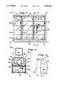
- FIG. 1is an elevational view of a display case of the present invention having doors mounted thereon and shelves mounted inside the case;
- FIG. 2is a partial cross-sectional view taken in the direction of arrows 2--2 of FIG. 1 showing lenses, for directing light, mounted on a surrounding frame near ends of one of the shelves;
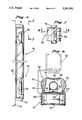
- FIG. 3is an enlarged cross-sectional view taken like FIG. 8, showing one of the lenses mounted on the frame, surrounding a fluorescent light tube;
- FIG. 4is a schematic view representing a portion of one of the lenses used to direct light
- FIG. 5is an enlarged, partial cross-sectional view showing portions of the surrounding frame and of a shelf, and schematically how the light-directing portion of one of the lenses directs light toward the shelf in order to more uniformly distribute light along the length of the shelf;
- FIG. 6is a side elevational view of upper and lower portions of one of the lenses shown surrounding a vertically-oriented fluorescent tube (middle portions of the lens and tube being omitted)
- FIG. 7is an enlarged, detailed front view of the upper end of the lens of FIG. 6;
- FIG. 8is an enlarged cross-sectional view of another embodiment of the lens taken in the direction of arrows 8--8 shown in FIG. 7;
- FIG. 9is an enlarged cross-sectional view of another embodiment of the lens taken like FIG. 8 having only one light-directing portion;
- FIG. 10is a graph schematically representing how light is distributed along the length of a shelf from a light source, such as a fluorescent light tube, located at one end of the shelf, and ideally distributed uniformly along the length of the shelf.
- a light sourcesuch as a fluorescent light tube
- a display case 10 of the present inventionhaving doors 12 mounted on a surrounding frame 14.
- the doors 12have glass panels 16, which allow someone, such as a customer in a supermarket, to look through the panels 16 at items 18 (see FIG. 2) displayed on shelves 20 inside the case 10.
- the items 18 inside the display case 10may or may not be refrigerated items 18, such as frozen foods.
- FIG. 2shows adjacent shelves 20 mounted at the same height or level within the display case 10.
- Each of the shelves 20has vertical supporting rods 22 and 24, horizontal supporting rods 26, and end rods 27.
- the end rods 27are mounted in column supports 28 and the back wall (not shown) of the display case 10.
- Front plates 30are mounted to rods 24 at the front of the shelves 20 and to the column supports 28 by hook members 32.
- the shelves 20may be constructed from sheet metal, may be injection molded, or the like.
- items 18 placed near the front and middle of shelves 20 in the display case 10are difficult to light or illuminate when vertical fluorescent lights or tubes 34, used to light the case 10, are located near the ends of the shelves 20, or near the front end corners of the shelves 20, as shown in FIG. 2.
- items 18 located near the front of the shelves 20 and close to the fluorescent tubes 34will be illuminated better than items 18 which are placed farther away from the tubes 34 and near the front and middle of the shelves 20.
- Items 18 placed near the front and middle of the shelves 20are not adequately illuminated by the light emitted from the tubes 34 because light from light sources such as tubes 34 follows the inverse-square law.
- the illuminance provided to each item 18 located along the front of one of the shelves 20 by a light source (tube 34)will be inversely proportional to the distance between the item 18 on the shelf 20 and the light source.
- the angle of incidence at which light rays strike the items 18will be greater for items 18 located near the tubes 34 than for items 18 located near the front and middle of the shelves 20. Therefore, more light will be reflected toward the eyes of customers from items 18 near the tubes 34.
- the present inventionprovides better lighting or illumination, or a more uniform lighting distribution along the length of the shelves 20, and provides more illumination for items 18 located near the front and middle of the shelves 20 than they would otherwise receive without the lens 36 of this invention.
- FIG. 2shows lenses 36 mounted on the frame 14 of the display case 10 near the ends or front end corners of the display shelves 20.
- the lenses 36are mounted about the fluorescent tubes 44 and are used to direct light beams 38 toward the shelves 20 (see FIG. 5) in order to provide better lighting or illumination for items 18 located near the front and middle of the shelves 20, and to distribute the light more uniformly along the length of the shelves 20.
- each lens 36has light-directing portions 40, connected by a top portion 42, which are located on opposite sides of one fluorescent tube 34.
- the lens 36is mounted to the frame 14 by end portions 44 which releasably engage channels 46 in a mullion cover 48 which is connected to a mullion 50 of the frame 14.
- the lens 36is sufficiently flexible to allow end portions 44 to releasably engage channels 46.
- a front plate 52is attached to the mullion 50.
- only one light-directing portion 40may be used for the lens 36, if shelves 20 on only one side of the tube 34 are to be illuminated (see FIG. 9).
- the light-directing portions 40 of the lenses 36are designed to direct light beams 38 toward the shelves as illustrated in FIG. 5, or to alter the light distribution along the length of the shelves 20 in a manner which shifts an amount of the light nearer the light source (tubes 34) to areas located farther from the light source.
- the lens 36is designed and mounted on the frame 14 so that the focal point 54 of each of the light-directing portions 40 of the lens 36 approximately falls on, or is coaxial with, the longitudinal axis of the fluorescent tube 34 surrounded by the lens 36.
- light rays emitted by the tube 34will be focused as substantially parallel light rays, or collimated light, directed along the length of the shelf 20 in a light beam 38 focused as substantially parallel light rays (see FIG. 5).
- the focused, substantially parallel light beam 38will not follow the inverse-square law, and items 18 located near the front and middle of the shelf 20 will be adequately illuminated.
- the lens 36may be designed to produce any desirable width for the beam 38.
- the lens 36is preferably made out of acrylic or plastic having an index of refraction (N d ) of 1.4917, and an Aberration (or Abbey) No. (V) of 57.2.
- N dindex of refraction
- VAberration (or Abbey) No.
- any suitable optical materialmay be used for the lens 36 such as glass, or the like.
- the lens 36is relatively compact, and may be easily fit between the frame 14 and columns 32.
- Parabolic reflectorsmay be used to direct parallel light rays. However, it would be difficult to fit larger size parabolic reflectors between the frame 14 and columns 32.
- reflectors 66may be mounted on the mullion cover 48 under the fluorescent tube 34 in order to reflect light upward or toward the light-directing portions 40.
- a reflector 68may also be attached to top portion 42 of the lens 36 to prevent too much light from exiting through the top of the lens 36, eliminating bright or hot spots near the ends of the shelves 20.
- the reflector 68which may be a reflective coating or a reflecting tape, or the like, reflects light downward and toward portions 40.
- part of top portion 42 of the lens 36may be glazed or otherwise prepared to prevent too much light from escaping or exiting through the top of the lens 36, or in order to diffuse light passing through the lens 36.
- intermediate top portions 70 of the lens 36, between top portion 42 and the light-directing portions 40,are not glazed or covered by reflector 68 (as shown in FIG. 3) in order to allow some light to exit the top of the lens 36 for the purpose of lighting the shelves 20 near the columns 28.
- FIG. 3shows a transverse cross-section of the lens 36.
- the lens 36may have a longitudinal length approximating the longitudinal length of the tube 34 it surrounds (see FIG. 6), or may be comprised of a number of shorter longitudinal segments or lengths having a combined length equalling that of the tube 34.
- the lights 34may be a number of separate tubes used for each level of shelves, or other types of lights used at different heights of the display case 10.
- a shorter version of the lens 36may be used with a spherical-shaped bulb instead of a tube.
- lens 36refers to any lens that directs or distributes light from a light source, such as tube 34, more uniformly over the length of a shelf.
- the light beam directed by the lensdoes not have to be a focused, substantially parallel light beam like beam 38 shown in FIG. 5.
- the lenses 36direct light toward the shelves 20, and more uniformly distribute light along the length of the shelves 20, or better illuminate items 18 placed toward the middle of the shelves 20. If lenses 36 are used at both ends of a shelf 20, then the corresponding light-directing portions 40 of both lenses 36 at the opposite ends of the shelf 20 will both direct light along the length of the shelf 20, combining to increase the illuminance along the shelf length and near the middle of the shelf 20. As such, the light-directing portions 40 of each lens 36 direct light toward adjacent shelves 20, or toward shelves 20 on both sides of the lens 36.
- FIG. 10is a graph schematically representing how light is distributed along the length of the shelf 20 by one of the tubes 34 located at one end of the shelf 20 following the inverse-square law (graph 72).
- graph 74 shown in FIG. 13ideally represents a uniform light distribution over the shelf 20 that is the goal of the present invention.
- FIGS. 6 and 7show how the elongated lens 36 fits around the fluorescent tube 34 which is connected to sockets 76 at the ends of the tube 34.
- FIG. 8shows the preferred embodiment of the lens 36 having elongated cylindrical portions 78, attached to end portions 44, that engage elongated apertures 80 in elongated extensions 82 of mullion cover 84.
- the lens 36is sufficiently flexible to allow portions 78 to engage apertures 80.
- any desirable meansmay be used to attach the end portions 44 of the lens 36 to the mullion cover 84. It is intended that the present invention not be limited by the means used to attach the lens 36 to the mullion covers 48 and 84, or to the surrounding frame 14.
- FIG. 9shows another embodiment of the lens 36 having only one light-directing portion 40.
- a lens designmay be used, for example, near the end of a shelf 20 located adjacent the side of the display case 10, or if it is desirable to direct light only toward one of two adjacent shelves 20.
- Light-directing portion 40has end portion 44 with elongated cylindrical portion 78 which engages elongated aperture 80 in elongated extension 82 of mullion cover 86 attached to mullion 88.
- Portion 40also has an elongated end portion 90 with elongated cylindrical portion 78 which engages elongated aperture 80 in elongated extension 92 of an upright portion 94 of the cover 86.
- the lens 36 of FIG. 9preferably has reflectors 98 and 100.
- Reflector 100directs light toward portion 40, and reflector 98 prevents light from exiting through elongated end portion 90 of the lens 36 and causing bright spots near the end of the shelf 20.
- reflector 98is sized so as to not cover portion 96 of the lens 36 between portions 40 and 90, allowing sufficient light to exit through portion 96 for the purpose of lighting or illuminating the end of the shelf 20.
- elongated end portion 90may be glazed or otherwise prepared to diffuse light through portion 90, if desired.
- the lens design shown in FIG. 9may be used in any combination with the lens designs shown in FIGS. 3 and 8. As such, any combination of features disclosed in this application may be combined in any desirable manner.
- the front portions of items positioned near the front and middle of display shelves, such as the flat front sides of box-shaped containers,will not be adequately illuminated by lights such as fluorescent tubes located at the ends of the shelves.
- the display case 10may have some shelves 20 that use lenses 36, and other shelves 20 for which lenses 36 are not used. As a result, certain items 18 on some of the shelves 20 will be lighted better than other items 18 on other shelves 20. This may be desirable, for example, if a store owner wishes to draw customers' attention to the items that are illuminated better by the lenses 36. Also, it may be desirable to provide better lighting for more popular items 18 located on waist-high shelves 20 within easy reach of customers. Less popular items 18 may be placed on the shelves that do not use lenses 36. Also, some of the adjacent shelves at the same height or level in the display case 10 (having more than one door 12) may use lenses 36, and some may not use lenses 36.
- the fluorescent tubes 34 and lenses 36do not have to be located exactly at the ends of the shelves 20 of the display case 10. As such, the tubes 34 and lenses 36 may be moved closer to or farther away from the middle of the shelves 20. In addition, the fluorescent tubes 34 and lenses 36 may be mounted on any part of the display case 10.
Landscapes
- Engineering & Computer Science (AREA)
- General Engineering & Computer Science (AREA)
- Architecture (AREA)
- Health & Medical Sciences (AREA)
- Public Health (AREA)
- Freezers Or Refrigerated Showcases (AREA)
- Arrangement Of Elements, Cooling, Sealing, Or The Like Of Lighting Devices (AREA)
- Illuminated Signs And Luminous Advertising (AREA)
- Circuit Arrangements For Discharge Lamps (AREA)
- Non-Portable Lighting Devices Or Systems Thereof (AREA)
- Securing Globes, Refractors, Reflectors Or The Like (AREA)
Abstract
Description
Claims (20)
Priority Applications (7)
| Application Number | Priority Date | Filing Date | Title |
|---|---|---|---|
| US08/032,549US5301092A (en) | 1992-04-08 | 1993-03-12 | Display case with lens lighting system |
| US08/163,276US5902034A (en) | 1992-04-08 | 1993-12-06 | Display case with lens lighting system |
| US08/486,523US5895111A (en) | 1992-04-08 | 1995-06-07 | Display case with lens lighting system |
| US09/294,449US6302557B1 (en) | 1992-04-08 | 1999-04-19 | Display case with lens lighting system |
| US09/417,614US6325523B1 (en) | 1992-04-08 | 1999-10-13 | Display case with lens lighting system |
| US09/977,480US20020089842A1 (en) | 1992-04-08 | 2001-10-15 | Display case with lens lighting system |
| US10/005,221US20020109980A1 (en) | 1992-04-08 | 2001-12-04 | Display case with lens lighting system |
Applications Claiming Priority (2)
| Application Number | Priority Date | Filing Date | Title |
|---|---|---|---|
| US86509692A | 1992-04-08 | 1992-04-08 | |
| US08/032,549US5301092A (en) | 1992-04-08 | 1993-03-12 | Display case with lens lighting system |
Related Parent Applications (1)
| Application Number | Title | Priority Date | Filing Date |
|---|---|---|---|
| US86509692AContinuation | 1992-04-08 | 1992-04-08 |
Related Child Applications (2)
| Application Number | Title | Priority Date | Filing Date |
|---|---|---|---|
| US08/163,276Continuation-In-PartUS5902034A (en) | 1992-04-08 | 1993-12-06 | Display case with lens lighting system |
| US08/486,523Continuation-In-PartUS5895111A (en) | 1992-04-08 | 1995-06-07 | Display case with lens lighting system |
Publications (1)
| Publication Number | Publication Date |
|---|---|
| US5301092Atrue US5301092A (en) | 1994-04-05 |
Family
ID=25344707
Family Applications (1)
| Application Number | Title | Priority Date | Filing Date |
|---|---|---|---|
| US08/032,549Expired - LifetimeUS5301092A (en) | 1992-04-08 | 1993-03-12 | Display case with lens lighting system |
Country Status (10)
| Country | Link |
|---|---|
| US (1) | US5301092A (en) |
| EP (1) | EP0637925B1 (en) |
| JP (1) | JPH07505302A (en) |
| CN (1) | CN1080154A (en) |
| AT (1) | ATE166771T1 (en) |
| AU (1) | AU3791693A (en) |
| DE (1) | DE69318980T2 (en) |
| DK (1) | DK0637925T3 (en) |
| ES (1) | ES2118943T3 (en) |
| WO (1) | WO1993020733A1 (en) |
Cited By (21)
| Publication number | Priority date | Publication date | Assignee | Title |
|---|---|---|---|---|
| US5471372A (en)* | 1993-12-06 | 1995-11-28 | Ardco, Inc. | Lighting system for commercial refrigerator doors |
| US5879070A (en)* | 1995-06-07 | 1999-03-09 | Anthony's Manufacturing Company, Inc. | Louvered lighting system |
| US5895111A (en)* | 1992-04-08 | 1999-04-20 | Anthony's Manufacturing Company, Inc. | Display case with lens lighting system |
| US5902034A (en)* | 1992-04-08 | 1999-05-11 | Anthony's Manufacturing Company, Inc. | Display case with lens lighting system |
| US5937666A (en)* | 1995-09-29 | 1999-08-17 | True Manufacturing Company, Inc. | Refrigerator unit with lighted door |
| US6148563A (en)* | 1999-03-25 | 2000-11-21 | Hussmann Corporation | Reach-in door for refrigerated merchandiser |
| US6406108B1 (en) | 1999-11-05 | 2002-06-18 | Specialty Equipment Companies, Inc. | Display case with door-mounted internal lighting |
| US6467859B2 (en) | 1999-12-08 | 2002-10-22 | Specialty Equipment Companies, Inc. | Environmentally controlled cabinet with sliding door within hinged door |
| US6578978B1 (en)* | 1999-06-07 | 2003-06-17 | Specialty Equipment Companies, Inc. | Display case having a mullion with recessed light fixtures |
| AT500642B1 (en)* | 1998-09-01 | 2006-07-15 | Prograph Graphische Produktion | LIGHTING DEVICE |
| US20070171647A1 (en)* | 2006-01-25 | 2007-07-26 | Anthony, Inc. | Control system for illuminated display case |
| US20080158858A1 (en)* | 2006-12-29 | 2008-07-03 | Hussmann Corporation | Refrigerated merchandiser with led lighting |
| US20080211359A1 (en)* | 2005-04-28 | 2008-09-04 | Carrier Corporation | Frameless Door Suspension |
| US20090021125A1 (en)* | 2007-07-20 | 2009-01-22 | Albert Weiss | Structure for Presenting and Displaying Goods |
| US20110051401A1 (en)* | 2009-08-27 | 2011-03-03 | Innovative Lighting, Inc. | Lighting system for cabinet display case |
| US7950833B1 (en)* | 2008-06-17 | 2011-05-31 | Genlyte Thomas Group Llc | Splay frame luminaire |
| US20110304253A1 (en)* | 2010-06-09 | 2011-12-15 | Hill Phoenix, Inc. | Refrigerated case with thermal door frame |
| US20140225485A1 (en)* | 2008-11-17 | 2014-08-14 | Versatility Tool Works & Manufacturing Company | Tool cabinet with downward opening transparent front door |
| US8845045B2 (en) | 2010-06-09 | 2014-09-30 | Hill Phoenix, Inc. | Door closing control and electrical connectivity system for refrigerated case |
| US20170370539A1 (en)* | 2016-06-22 | 2017-12-28 | Wanjiong Lin | Led bar lighting and exhibition cabinet having same |
| US10539316B2 (en)* | 2017-11-28 | 2020-01-21 | Self Electronics Co., Ltd. | Light distribution system for freezer |
Families Citing this family (9)
| Publication number | Priority date | Publication date | Assignee | Title |
|---|---|---|---|---|
| AUPR149200A0 (en)* | 2000-11-15 | 2000-12-07 | Checkmate International Pty Ltd | Shelving system |
| DE10223238B4 (en)* | 2002-05-24 | 2014-05-15 | Carrier Corporation | Goods presentation floor with lighting rail |
| WO2005119124A2 (en)* | 2004-05-26 | 2005-12-15 | Gelcore Llc | Led lighting systems for product display cases |
| KR100576061B1 (en)* | 2004-08-24 | 2006-05-03 | 주식회사 시공테크 | Illumination of showcase for cultural property |
| KR100576060B1 (en)* | 2004-08-24 | 2006-05-03 | 주식회사 시공테크 | Illumination of showcase for cultural property |
| EP2732729B1 (en)* | 2012-11-16 | 2018-12-26 | Diam UK Ltd | Shelf tray with lighting unit |
| CN104433522A (en)* | 2014-11-17 | 2015-03-25 | 刘桂芹 | Transparent showcase |
| CN107105907B (en)* | 2014-12-23 | 2020-03-10 | 开利公司 | Refrigerated goods showcase |
| CN106931352B (en)* | 2015-12-31 | 2020-01-21 | 赛尔富电子有限公司 | Exhibition cabinet |
Citations (31)
| Publication number | Priority date | Publication date | Assignee | Title |
|---|---|---|---|---|
| US2248638A (en)* | 1937-02-22 | 1941-07-08 | Merton Thomas Ralph | Sheet material with prismatic surfaces |
| US2293924A (en)* | 1941-09-08 | 1942-08-25 | Swanson Carl Edward | Fluorescent table lamp construction |
| US2476352A (en)* | 1946-04-24 | 1949-07-19 | Crouse Hinds Co | Lighting fixture |
| US2533661A (en)* | 1948-03-18 | 1950-12-12 | Patent License Corp | Fixture assembly for elongated tubular lamps |
| US2551710A (en)* | 1945-05-04 | 1951-05-08 | Extruded Plastics Inc | Light diffusing thermoplastic tube to encircle an elongated lighting element |
| US2563635A (en)* | 1947-07-18 | 1951-08-07 | Morris W Askin | Lighting fixture for elongated tubular lamps |
| US2583939A (en)* | 1948-08-28 | 1952-01-29 | Plasti Cation Corp | Light-diffusing shield for elongated tubular lamps |
| US2807710A (en)* | 1956-07-30 | 1957-09-24 | Fred E Williams | Inspection lamp |
| US3242331A (en)* | 1964-01-27 | 1966-03-22 | Wray K Behringer | Portable light |
| US3808495A (en)* | 1972-08-21 | 1974-04-30 | Malcolite Corp | Guard for illumination tubes |
| US4017130A (en)* | 1975-11-06 | 1977-04-12 | Structural Concepts Corporation | Display case |
| US4390930A (en)* | 1981-04-15 | 1983-06-28 | Herst Lighting Co. | Indirect lighting fixture with improved light control |
| US4393323A (en)* | 1981-01-23 | 1983-07-12 | Plascore, Inc. | Fluorescent lamp shield |
| US4432044A (en)* | 1981-03-26 | 1984-02-14 | Steelcase Inc. | Task lighting system |
| US4450509A (en)* | 1982-08-17 | 1984-05-22 | Thorn Emi Plc | Lanterns for area lighting |
| US4496216A (en)* | 1982-12-30 | 1985-01-29 | Polaroid Corporation | Method and apparatus for exposing photosensitive material |
| US4609978A (en)* | 1983-05-09 | 1986-09-02 | President of Yamagata University | Lighting apparatus with illuminance equalizing lens |
| US4611266A (en)* | 1985-07-19 | 1986-09-09 | Cable Electric Products, Inc. | Refractor for electric light wall unit |
| US4660934A (en)* | 1984-03-21 | 1987-04-28 | Kokusai Denshin Denwa Kabushiki Kaisha | Method for manufacturing diffraction grating |
| US4734836A (en)* | 1984-09-29 | 1988-03-29 | Masataka Negishi | Lighting apparatus |
| US4792197A (en)* | 1985-07-19 | 1988-12-20 | Hitachi, Ltd. | Fabrication method and equipment for diffraction gratings |
| US4793680A (en)* | 1986-04-25 | 1988-12-27 | Stc Plc | Induced grating devices and method of making same |
| US4806454A (en)* | 1984-12-27 | 1989-02-21 | Sharp Kabushiki Kaisha | Method for the formation of a diffraction grating |
| US4858087A (en)* | 1987-05-01 | 1989-08-15 | Lee Vande Sande | Universal circular enclosure for standard strip fluorescent fixture |
| US4924368A (en)* | 1989-01-06 | 1990-05-08 | Duro-Test Corporation | Fluorescent lamp with protective shield |
| US4979078A (en)* | 1989-07-17 | 1990-12-18 | Amstore Corporation | Lighted display case |
| US5016146A (en)* | 1989-10-10 | 1991-05-14 | Ardco, Inc. | Refrigerator light assembly with bulb insulating and protective sleeve |
| US5022720A (en)* | 1990-04-30 | 1991-06-11 | Structural Concepts Corporation | Display case |
| US5034861A (en)* | 1989-12-22 | 1991-07-23 | Raytheon Company | Shelf track lighting |
| US5080465A (en)* | 1988-03-18 | 1992-01-14 | Instruments S.A. | Diffraction grating and method of making |
| US5116461A (en)* | 1991-04-22 | 1992-05-26 | Motorola, Inc. | Method for fabricating an angled diffraction grating |
Family Cites Families (5)
| Publication number | Priority date | Publication date | Assignee | Title |
|---|---|---|---|---|
| DE491082C (en)* | 1928-01-27 | 1930-02-07 | Gaz Et D Electricite Du Sud Es | Gas lighting body with hanging glow stems and facilities to increase their efficiency |
| DE3541573A1 (en)* | 1985-11-25 | 1987-05-27 | Roland Weis | Lighting device for a plurality of display items |
| FR2654602B1 (en)* | 1989-11-22 | 1994-06-03 | Couthier Philippe | DISPLAY CABINET. |
| DE4003692A1 (en)* | 1990-02-07 | 1991-08-08 | Linde Ag | GOODS SALES SHELF |
| US5040101A (en)* | 1990-04-19 | 1991-08-13 | Aspenwall John E | Lighting system for display cabinet |
- 1993
- 1993-03-05AUAU37916/93Apatent/AU3791693A/ennot_activeAbandoned
- 1993-03-05ATAT93907239Tpatent/ATE166771T1/ennot_activeIP Right Cessation
- 1993-03-05WOPCT/US1993/001997patent/WO1993020733A1/enactiveIP Right Grant
- 1993-03-05DEDE69318980Tpatent/DE69318980T2/ennot_activeExpired - Fee Related
- 1993-03-05JPJP5516884Apatent/JPH07505302A/enactivePending
- 1993-03-05EPEP93907239Apatent/EP0637925B1/ennot_activeExpired - Lifetime
- 1993-03-05ESES93907239Tpatent/ES2118943T3/ennot_activeExpired - Lifetime
- 1993-03-05DKDK93907239Tpatent/DK0637925T3/enactive
- 1993-03-12USUS08/032,549patent/US5301092A/ennot_activeExpired - Lifetime
- 1993-03-15CNCN93104485Apatent/CN1080154A/enactivePending
Patent Citations (32)
| Publication number | Priority date | Publication date | Assignee | Title |
|---|---|---|---|---|
| US2248638A (en)* | 1937-02-22 | 1941-07-08 | Merton Thomas Ralph | Sheet material with prismatic surfaces |
| US2293924A (en)* | 1941-09-08 | 1942-08-25 | Swanson Carl Edward | Fluorescent table lamp construction |
| US2551710A (en)* | 1945-05-04 | 1951-05-08 | Extruded Plastics Inc | Light diffusing thermoplastic tube to encircle an elongated lighting element |
| US2476352A (en)* | 1946-04-24 | 1949-07-19 | Crouse Hinds Co | Lighting fixture |
| US2563635A (en)* | 1947-07-18 | 1951-08-07 | Morris W Askin | Lighting fixture for elongated tubular lamps |
| US2533661A (en)* | 1948-03-18 | 1950-12-12 | Patent License Corp | Fixture assembly for elongated tubular lamps |
| US2583939A (en)* | 1948-08-28 | 1952-01-29 | Plasti Cation Corp | Light-diffusing shield for elongated tubular lamps |
| US2807710A (en)* | 1956-07-30 | 1957-09-24 | Fred E Williams | Inspection lamp |
| US3242331A (en)* | 1964-01-27 | 1966-03-22 | Wray K Behringer | Portable light |
| US3808495A (en)* | 1972-08-21 | 1974-04-30 | Malcolite Corp | Guard for illumination tubes |
| US4017130A (en)* | 1975-11-06 | 1977-04-12 | Structural Concepts Corporation | Display case |
| US4393323A (en)* | 1981-01-23 | 1983-07-12 | Plascore, Inc. | Fluorescent lamp shield |
| US4432044A (en)* | 1981-03-26 | 1984-02-14 | Steelcase Inc. | Task lighting system |
| US4390930A (en)* | 1981-04-15 | 1983-06-28 | Herst Lighting Co. | Indirect lighting fixture with improved light control |
| US4450509A (en)* | 1982-08-17 | 1984-05-22 | Thorn Emi Plc | Lanterns for area lighting |
| US4496216A (en)* | 1982-12-30 | 1985-01-29 | Polaroid Corporation | Method and apparatus for exposing photosensitive material |
| US4609978A (en)* | 1983-05-09 | 1986-09-02 | President of Yamagata University | Lighting apparatus with illuminance equalizing lens |
| US4660934A (en)* | 1984-03-21 | 1987-04-28 | Kokusai Denshin Denwa Kabushiki Kaisha | Method for manufacturing diffraction grating |
| US4734836A (en)* | 1984-09-29 | 1988-03-29 | Masataka Negishi | Lighting apparatus |
| US4806454A (en)* | 1984-12-27 | 1989-02-21 | Sharp Kabushiki Kaisha | Method for the formation of a diffraction grating |
| US4997747A (en)* | 1984-12-27 | 1991-03-05 | Sharp Kabushiki Kaisha | Method for the formation of a diffraction grating |
| US4792197A (en)* | 1985-07-19 | 1988-12-20 | Hitachi, Ltd. | Fabrication method and equipment for diffraction gratings |
| US4611266A (en)* | 1985-07-19 | 1986-09-09 | Cable Electric Products, Inc. | Refractor for electric light wall unit |
| US4793680A (en)* | 1986-04-25 | 1988-12-27 | Stc Plc | Induced grating devices and method of making same |
| US4858087A (en)* | 1987-05-01 | 1989-08-15 | Lee Vande Sande | Universal circular enclosure for standard strip fluorescent fixture |
| US5080465A (en)* | 1988-03-18 | 1992-01-14 | Instruments S.A. | Diffraction grating and method of making |
| US4924368A (en)* | 1989-01-06 | 1990-05-08 | Duro-Test Corporation | Fluorescent lamp with protective shield |
| US4979078A (en)* | 1989-07-17 | 1990-12-18 | Amstore Corporation | Lighted display case |
| US5016146A (en)* | 1989-10-10 | 1991-05-14 | Ardco, Inc. | Refrigerator light assembly with bulb insulating and protective sleeve |
| US5034861A (en)* | 1989-12-22 | 1991-07-23 | Raytheon Company | Shelf track lighting |
| US5022720A (en)* | 1990-04-30 | 1991-06-11 | Structural Concepts Corporation | Display case |
| US5116461A (en)* | 1991-04-22 | 1992-05-26 | Motorola, Inc. | Method for fabricating an angled diffraction grating |
Non-Patent Citations (6)
| Title |
|---|
| Book: Eugene Hecht and Alfred Zajac, Addison Wesley Publishing Company, Inc., Optics, Geometrical Optics, pp. 108 110 and 167 169, Redding, Massachusetts, 1979.* |
| Book: Eugene Hecht and Alfred Zajac, Addison-Wesley Publishing Company, Inc., Optics, "Geometrical Optics," pp. 108-110 and 167-169, Redding, Massachusetts, 1979. |
| Book: Laurin Publishing Co., The Photonics Dictonary, p. D 23, Pittsfield, Massachusetts, 1991.* |
| Book: Laurin Publishing Co., The Photonics Dictonary, p. D-23, Pittsfield, Massachusetts, 1991. |
| Paper: Technical Education Research Center SW, Course VI Laser and Electro Optic Components, pp. 20 21, Waco, Texas, Aug. 1980.* |
| Paper: Technical Education Research Center-SW, "Course VI Laser and Electro-Optic Components," pp. 20-21, Waco, Texas, Aug. 1980. |
Cited By (29)
| Publication number | Priority date | Publication date | Assignee | Title |
|---|---|---|---|---|
| US6302557B1 (en) | 1992-04-08 | 2001-10-16 | New Anthony, Inc. | Display case with lens lighting system |
| US5895111A (en)* | 1992-04-08 | 1999-04-20 | Anthony's Manufacturing Company, Inc. | Display case with lens lighting system |
| US5902034A (en)* | 1992-04-08 | 1999-05-11 | Anthony's Manufacturing Company, Inc. | Display case with lens lighting system |
| US5471372A (en)* | 1993-12-06 | 1995-11-28 | Ardco, Inc. | Lighting system for commercial refrigerator doors |
| US5879070A (en)* | 1995-06-07 | 1999-03-09 | Anthony's Manufacturing Company, Inc. | Louvered lighting system |
| US5937666A (en)* | 1995-09-29 | 1999-08-17 | True Manufacturing Company, Inc. | Refrigerator unit with lighted door |
| AT500642B1 (en)* | 1998-09-01 | 2006-07-15 | Prograph Graphische Produktion | LIGHTING DEVICE |
| US6393768B1 (en) | 1999-03-25 | 2002-05-28 | Hussmann Corporation | Method of making reach-in door for refrigerated merchandiser |
| US6401399B1 (en) | 1999-03-25 | 2002-06-11 | Hussmann Corporation | Reach-in refrigerated merchandiser |
| US6148563A (en)* | 1999-03-25 | 2000-11-21 | Hussmann Corporation | Reach-in door for refrigerated merchandiser |
| US6578978B1 (en)* | 1999-06-07 | 2003-06-17 | Specialty Equipment Companies, Inc. | Display case having a mullion with recessed light fixtures |
| US6406108B1 (en) | 1999-11-05 | 2002-06-18 | Specialty Equipment Companies, Inc. | Display case with door-mounted internal lighting |
| US6467859B2 (en) | 1999-12-08 | 2002-10-22 | Specialty Equipment Companies, Inc. | Environmentally controlled cabinet with sliding door within hinged door |
| US20080211359A1 (en)* | 2005-04-28 | 2008-09-04 | Carrier Corporation | Frameless Door Suspension |
| US20070171647A1 (en)* | 2006-01-25 | 2007-07-26 | Anthony, Inc. | Control system for illuminated display case |
| US20080158858A1 (en)* | 2006-12-29 | 2008-07-03 | Hussmann Corporation | Refrigerated merchandiser with led lighting |
| US7824056B2 (en) | 2006-12-29 | 2010-11-02 | Hussmann Corporation | Refrigerated merchandiser with LED lighting |
| US20090021125A1 (en)* | 2007-07-20 | 2009-01-22 | Albert Weiss | Structure for Presenting and Displaying Goods |
| US7950833B1 (en)* | 2008-06-17 | 2011-05-31 | Genlyte Thomas Group Llc | Splay frame luminaire |
| US20140225485A1 (en)* | 2008-11-17 | 2014-08-14 | Versatility Tool Works & Manufacturing Company | Tool cabinet with downward opening transparent front door |
| US9089963B2 (en)* | 2008-11-17 | 2015-07-28 | Versatility Tool Works & Manufacturing Company | Tool cabinet with downward opening transparent front door |
| US9523469B2 (en)* | 2009-08-27 | 2016-12-20 | Innovative Lighting, Inc. | Lighting system for cabinet display case |
| US20110051401A1 (en)* | 2009-08-27 | 2011-03-03 | Innovative Lighting, Inc. | Lighting system for cabinet display case |
| US8845045B2 (en) | 2010-06-09 | 2014-09-30 | Hill Phoenix, Inc. | Door closing control and electrical connectivity system for refrigerated case |
| US20110304253A1 (en)* | 2010-06-09 | 2011-12-15 | Hill Phoenix, Inc. | Refrigerated case with thermal door frame |
| US9157675B2 (en)* | 2010-06-09 | 2015-10-13 | Hill Phoenix, Inc. | Insulated case construction |
| US20170370539A1 (en)* | 2016-06-22 | 2017-12-28 | Wanjiong Lin | Led bar lighting and exhibition cabinet having same |
| US10156328B2 (en)* | 2016-06-22 | 2018-12-18 | Self Electronics Co., Ltd. | LED bar lighting and exhibition cabinet having same |
| US10539316B2 (en)* | 2017-11-28 | 2020-01-21 | Self Electronics Co., Ltd. | Light distribution system for freezer |
Also Published As
| Publication number | Publication date |
|---|---|
| DE69318980T2 (en) | 1998-09-24 |
| EP0637925B1 (en) | 1998-06-03 |
| DK0637925T3 (en) | 1999-02-01 |
| AU3791693A (en) | 1993-11-18 |
| ES2118943T3 (en) | 1998-10-01 |
| ATE166771T1 (en) | 1998-06-15 |
| CN1080154A (en) | 1994-01-05 |
| EP0637925A4 (en) | 1995-05-24 |
| EP0637925A1 (en) | 1995-02-15 |
| JPH07505302A (en) | 1995-06-15 |
| DE69318980D1 (en) | 1998-07-09 |
| WO1993020733A1 (en) | 1993-10-28 |
Similar Documents
| Publication | Publication Date | Title |
|---|---|---|
| US5301092A (en) | Display case with lens lighting system | |
| US5902034A (en) | Display case with lens lighting system | |
| US5895111A (en) | Display case with lens lighting system | |
| US6325523B1 (en) | Display case with lens lighting system | |
| US5471372A (en) | Lighting system for commercial refrigerator doors | |
| US6726341B2 (en) | LED illumination for cold storage compartments | |
| US6578978B1 (en) | Display case having a mullion with recessed light fixtures | |
| US4989948A (en) | Reflective sheeting material | |
| US20110058357A1 (en) | Led lighting assembly with leds having different viewing angles | |
| US5722747A (en) | Merchandising display | |
| US4148533A (en) | Display rack for packaged and dispensable beverages | |
| US5297863A (en) | Display case with shaped lighted shelves | |
| US6533130B1 (en) | Illuminated chip rack | |
| US20190239660A1 (en) | Product display and method of manufacture | |
| JP2010082115A (en) | Showcase | |
| US3823500A (en) | Advertising and promotional display apparatus | |
| NL1022656C2 (en) | Display device, e.g. showcase for use in shop, has optical redirection components provided on front edges of shelves | |
| EP2168461A1 (en) | Display apparatus | |
| JP2004533085A (en) | Lighting fixture with elongated light source and back reflector | |
| EP2098140A1 (en) | Display apparatus and method of illuminating | |
| JPH0720805Y2 (en) | Lighting equipment in the freezer refrigeration showcase | |
| JP2000237012A (en) | Illumination device for freezing, refrigerating and non- refrigerating showcase | |
| JPH07151454A (en) | Display case | |
| JP2003217015A (en) | Product sample display device and product sample | |
| JPH0633272U (en) | vending machine |
Legal Events
| Date | Code | Title | Description |
|---|---|---|---|
| STPP | Information on status: patent application and granting procedure in general | Free format text:APPLICATION UNDERGOING PREEXAM PROCESSING | |
| AS | Assignment | Owner name:CHEMICAL BANK, NEW YORK Free format text:SECURITY INTEREST;ASSIGNOR:ANTHONY'S MANUFACTURING COMPANY, INC.;REEL/FRAME:007437/0368 Effective date:19950331 | |
| AS | Assignment | Owner name:FIRST NATIONAL BANK OF BOSTON, THE, MASSACHUSETTS Free format text:SECURITY AGREEMENT;ASSIGNOR:ANTHONY'S MANUFACTURING COMPANY, INC.;REEL/FRAME:008545/0385 Effective date:19970221 | |
| FPAY | Fee payment | Year of fee payment:4 | |
| AS | Assignment | Owner name:NEW ANTHONY, INC., CALIFORNIA Free format text:ASSIGNMENT OF ASSIGNORS INTEREST;ASSIGNOR:ANTHONY'S MANUFACTURING COMPANY, INC.;REEL/FRAME:009703/0895 Effective date:19981222 Owner name:ANTHONY'S MANUFACTURING COMPANY, INC., CALIFORNIA Free format text:TERMINATION OF SECURITY INTEREST;ASSIGNOR:CHASE-MANHATTAN BANK, SUCCESSOR BY MERGER TO CHEMICAL BANK, SBM MANUFACTURER'S HANOVER TRUST COMPANY;REEL/FRAME:009719/0230 Effective date:19981221 | |
| AS | Assignment | Owner name:ANTHONY'S MANUFACTURING COMPANY, INC., CALIFORNIA Free format text:TERMINATION OF SECURITY INTEREST AND QUITCLAIM;ASSIGNOR:BANKBOSTON, N.A. F/K/A THE FIRST NATIONAL BANK OF BOSTON;REEL/FRAME:009737/0089 Effective date:19981222 | |
| AS | Assignment | Owner name:SUNTRUST BANK, ATLANTA, GEORGIA Free format text:ASSIGNMENT & SECURITY AGREEMENT;ASSIGNOR:NEW ANTHONY, INC.;REEL/FRAME:010977/0740 Effective date:19981222 | |
| FPAY | Fee payment | Year of fee payment:8 | |
| AS | Assignment | Owner name:MERRILL LYNCH CAPITAL, ILLINOIS Free format text:SECURITY INTEREST;ASSIGNOR:ANTHONY, INC.;REEL/FRAME:015127/0399 Effective date:20040901 | |
| AS | Assignment | Owner name:ANTHONY, INC. (FKA NEW ANTHONY, INC.), CALIFORNIA Free format text:RELEASE OF SECURITY INTEREST;ASSIGNOR:GENERAL ELECTRIC CAPITAL CORPORATION, AS AGENT (FKA SUN TRUST BANK, ATLANTA);REEL/FRAME:015156/0782 Effective date:20040901 | |
| FPAY | Fee payment | Year of fee payment:12 | |
| AS | Assignment | Owner name:ANTHONY, INC., CALIFORNIA Free format text:CHANGE OF NAME;ASSIGNOR:NEW ANTHONY, INC.;REEL/FRAME:026405/0720 Effective date:19990126 | |
| AS | Assignment | Owner name:ARES CAPITAL CORPORATION, NEW YORK Free format text:SECURITY AGREEMENT;ASSIGNORS:ANTHONY, INC.;PIKE MACHINE PRODUCTS, INC.;EQUIPMENT BROKERS, INC.;REEL/FRAME:026465/0010 Effective date:20110615 | |
| AS | Assignment | Owner name:ANTHONY, INC., CALIFORNIA Free format text:RELEASE BY SECURED PARTY;ASSIGNOR:ARES CAPITAL CORPORATION;REEL/FRAME:026801/0284 Effective date:20110824 Owner name:PIKE MACHINE PRODUCTS, INC., CALIFORNIA Free format text:RELEASE BY SECURED PARTY;ASSIGNOR:ARES CAPITAL CORPORATION;REEL/FRAME:026801/0284 Effective date:20110824 Owner name:EQUIPMENT BROKERS, INC., CALIFORNIA Free format text:RELEASE BY SECURED PARTY;ASSIGNOR:ARES CAPITAL CORPORATION;REEL/FRAME:026801/0284 Effective date:20110824 | |
| AS | Assignment | Owner name:GENERAL ELECTRIC CAPITAL CORPORATION, ILLINOIS Free format text:SECURITY AGREEMENT;ASSIGNORS:ANTHONY, INC.;PIKE MACHINE PRODUCTS, INC.;EQUIPMENT BROKERS, INC.;REEL/FRAME:026812/0917 Effective date:20110824 | |
| AS | Assignment | Owner name:PIKE MACHINE PRODUCTS, INC., CALIFORNIA Free format text:TERMINATION AND RELEASE OF PATENT SECURITY AGREEMENT RECORDED ON AUGUST 26, 2011 AT REEL/FRAME 26812/0917;ASSIGNOR:GENERAL ELECTRIC CAPITAL CORPORATION, AS ADMINISTRATIVE AGENT;REEL/FRAME:029396/0766 Effective date:20121130 Owner name:ANTHONY, INC., CALIFORNIA Free format text:TERMINATION AND RELEASE OF PATENT SECURITY AGREEMENT RECORDED ON AUGUST 26, 2011 AT REEL/FRAME 26812/0917;ASSIGNOR:GENERAL ELECTRIC CAPITAL CORPORATION, AS ADMINISTRATIVE AGENT;REEL/FRAME:029396/0766 Effective date:20121130 Owner name:EQUIPMENT BROKERS, INC., CALIFORNIA Free format text:TERMINATION AND RELEASE OF PATENT SECURITY AGREEMENT RECORDED ON AUGUST 26, 2011 AT REEL/FRAME 26812/0917;ASSIGNOR:GENERAL ELECTRIC CAPITAL CORPORATION, AS ADMINISTRATIVE AGENT;REEL/FRAME:029396/0766 Effective date:20121130 |