US5301036A - Image orientation control - Google Patents
Image orientation controlDownload PDFInfo
- Publication number
- US5301036A US5301036AUS07/862,916US86291692AUS5301036AUS 5301036 AUS5301036 AUS 5301036AUS 86291692 AUS86291692 AUS 86291692AUS 5301036 AUS5301036 AUS 5301036A
- Authority
- US
- United States
- Prior art keywords
- orientation
- image
- input
- output
- document
- Prior art date
- Legal status (The legal status is an assumption and is not a legal conclusion. Google has not performed a legal analysis and makes no representation as to the accuracy of the status listed.)
- Expired - Lifetime
Links
Images


Classifications
- G—PHYSICS
- G06—COMPUTING OR CALCULATING; COUNTING
- G06T—IMAGE DATA PROCESSING OR GENERATION, IN GENERAL
- G06T3/00—Geometric image transformations in the plane of the image
- G06T3/60—Rotation of whole images or parts thereof
- G06T3/606—Rotation of whole images or parts thereof by memory addressing or mapping
- H—ELECTRICITY
- H04—ELECTRIC COMMUNICATION TECHNIQUE
- H04N—PICTORIAL COMMUNICATION, e.g. TELEVISION
- H04N1/00—Scanning, transmission or reproduction of documents or the like, e.g. facsimile transmission; Details thereof
- H04N1/387—Composing, repositioning or otherwise geometrically modifying originals
- H04N1/3877—Image rotation
Definitions
- the inventionrelates to electronic printers and printing systems, and more particularly, to accomplishment of certain jobs in such devices which provide automatic rotation of images.
- the Xerox DocuTechprovides a feature that allows specification of input orientation of an image and separately allows specification of output plex, independently of input orientation. Additionally, DocuTech allows printing signatures, which are always duplexed sheets, and requires specification of input orientation and plex and a limited selection of output orientation. Users, however, have difficulties in relating the selection of plex of a document with its image orientation. Accordingly, it is desirable to have full control of specifying input orientation and plex, as well as output orientation and plex, and provide operator understandable indicia of the same.
- the present inventionis directed to a rotation/page placement method, which the operator selects by providing information about orientation of an input image and desired output orientation and placement, from a group of given options.
- rotation of the image as requiredis made.
- a digital copierhaving an image input for receiving digitally represented images from a source of input information such as an image input scanner; a controller having the capability of rotating an image in at least 90° increments and which can provide such rotation in accordance with a preprogrammed set of commands; a user interface, connected to the controller, and for directing information about the orientation of the input image, and information about output orientation and placement in accordance with one of a plurality of selectable output orientation; and an output, such as a binary printer, to which the controller may direct reoriented image data.
- orientationwhen printing signatures, orientation can be accomplished based on known information about the input orientation, signature format, and output print sheet size and orientation.
- FIG. 1is a view depicting an electronic printing system incorporating the present invention
- FIG. 2is a block diagram depicting the major elements of the printing system shown in FIG. 1;
- FIG. 3is a frontal view illustrating the principal mechanical components of the printing system shown in FIG. 1;
- FIG. 4is a schematic view showing certain construction details of the document scanner for the printing system shown in FIG. 1;
- FIGS. 5A, 5B, and 5Ccomprise a schematic block diagram showing the major parts of the control section for the printing system shown in FIG. 1;
- FIG. 6is a block diagram of the Operating System, together with Printed Wiring Boards and shared line connections for the printing system shown in FIG. 1;
- FIG. 7is a view depicting an exemplary job programming ticket and job scorecard displayed on the User Interface (UI) touchscreen of the printing system shown in FIG. 1;
- UIUser Interface
- FIG. 8Ais a view depicting standard plex selection
- FIG. 8Bis a view depicting plex selection with orientation selection
- FIG. 9is a view illustrating duplex output print selection with orientation selection
- FIG. 10is a view depicting signature (book) output print selection with orientation selection.
- FIG. 11is a view showing how rotation must occur in standard sets of signatures.
- image input section 4has both remote and on-site image inputs, enabling system 2 to provide network, scan, and print services.
- Other system combinationsmay be envisioned such as a stand alone printing system with on-site image input (i.e., a scanner), controller, and printer; a network printing system with remote input, controller, and printer; etc. While a specific printing system is shown and described, the present invention may be used with other types of printing systems.
- printer section 8may instead use a different printer type such as ink jet, ionographic, thermal, photographic, etc., and furthermore may be incorporated in electronic display systems, such as CRTs, LCDs, LEDs, etc. or else other image scanning/processing/recording systems, or else other signal transmitting/receiving, recording systems, etc. as well.
- printer typesuch as ink jet, ionographic, thermal, photographic, etc.
- electronic display systemssuch as CRTs, LCDs, LEDs, etc. or else other image scanning/processing/recording systems, or else other signal transmitting/receiving, recording systems, etc. as well.
- image input section 4has a network 5 with a suitable communication channel such as a telephone line or Local Area Network (LAN) connection enabling image data in the form of image signals or pixels from one or more remote sources to be input to system 2 for processing.
- a suitable communication channelsuch as a telephone line or Local Area Network (LAN) connection
- PDLPage Description Language
- suitable conversion means(not shown) are provided.
- Other remote sources of image datasuch as streaming tape, floppy disk, etc. may be envisioned.
- section 4has a document scanner section 6 with a Universal Document Handler (UDH) 35 for the purpose of automatically and sequentially placing and locating sets of multiple documents 22 for scanning on a transparent platen 20.
- UDHUniversal Document Handler
- One or more linear light sensitive arrays 24are supported for reciprocating scanning movement below platen 20.
- CCDCharge-Coupled Device
- Scanning system processor 25communicates with the system controller 54 (described below) and includes a scanner system control 25a, an automatic gain control printing wiring board (AGCPWB) 25b, and a processor 25c.
- AGCPWB 25bconverts the analog image signals output by array 24 to digitally represented facsimile signals and processor 25c processes the digital image signals as required to enable controller section 7 to store and handle the image in the form and order required to carry out the job programmed. After processing, the image signals are output to controller section 7. Image pixels derived from net 5 are similarly input to processor 25.
- Processor 25also provides enhancements and changes to the image signals such as filtering, thresholding, screening, cropping, scaling (reduction/enlargement), etc. Following any changes and adjustments in the job program which affect these image processing parameters, the document must be rescanned to capture the specified modification within scan processor 25.
- UDH 35Universal Document Handler
- RDHRecirculating Document Handling
- SADHSemi-Automatic Document Handling
- a manual mode including a Book mode and a Computer Forms Feeder (CFF) modeare also provided, the latter to accommodate documents in the form of computer fanfold.
- UDH 35has a document tray 37 in which documents 22 are arranged in stacks or batches. The documents 22 in tray 37 are advanced by vacuum feed belt 40 and document feed rolls 41 and document feed belt 42 onto platen 20 where the document is scanned by array 24. Following scanning, the document is removed from platen 20 by belt 42 and returned to tray 37 by document feed rolls 44.
- a document entry slot 46provides access to the document feed belt 42 between tray 37 and platen 20 through which individual documents may be inserted manually for transport to platen 20. Feed rolls 49 behind slot 46 form a nip for engaging and feeding the document to feed belt 42 and onto platen 20. Following scanning, the document is removed from platen 20 and discharged into catch tray 48.
- computer forms materialis fed through slot 46 and advanced by feed rolls 49 to document feed belt 42 which in turn advances a page of the fanfold material into position on platen 20.
- printer section 8comprises a laser type printer, and for purposes of explanation, is separated into a Raster Output Scanner (ROS) section 87, Print Module Section 95, Paper Supply section 107, Finisher 120, and Printer System Control 128.
- ROS 95has a laser 91, the beam of which is split into two imaging beams 94 (only one shown for description purposes). Each beam 94 is modulated in accordance with the content of an image signal input by acousto-optic modulator 92 to provide dual imaging beams 94.
- Beams 94are scanned across a moving photoreceptor 98 of Print Module 95 by the mirrored facets of a rotating polygon 100 to expose two image lines on photoreceptor 98 with each scan, and create the latent electrostatic images represented by the image signal input to modulator 92.
- Photoreceptor 98is uniformly charged by corotrons 102 at a charging station preparatory to exposure by imaging beams 94.
- the latent electrostatic imagesare developed by developer 104 and transferred at transfer station 106 to a print media 108 delivered by Paper Supply section 107.
- Media 108may comprise any of a variety of sheet sizes, types, and colors.
- the print mediais brought forward in timed registration with the developed image on photoreceptor 98 from either a main paper tray 110 or from auxiliary paper trays 112 or 114.
- the developed image transferred to the print media 108is permanently fixed or fused by fuser 116 and the resulting prints discharged to either output tray 118, or to finisher 120.
- Finisher 120includes a stitcher 122 for stitching or stapling the prints together to form books and a thermal binder 124 for adhesively binding the prints into books.
- Other finishing optionssuch as slitting, perforating, saddle stitching, folding, trimming, or the like, either singly or in combination may also be accommodated in alternate finishing modules.
- controller section 7is, for explanation purposes, divided into an image input controller 50, User Interface (UI) 52, system controller 54, main memory 56, image manipulation section 58, and image output controller 60.
- the units 50, 54, 56, 58, 60comprise a system 55 which may also generally be referred to as the "Electronic Subsystem” (ESS).
- ESSElectronic Subsystem
- the scanned image data input from processor 25 of scanner section 6 to controller section 7is compressed by image compressor processor 51 of image input controller 50 on PWB 70-3.
- image compressor/processor 51As the image data passes through compressor/processor 51, it is segmented into slices N scanlines wide, each slice having a slice pointer.
- the compressed image data together with slice pointers and any related image descriptors providing image specific informationare placed in an image file.
- the image files, which represent different print jobs,are temporarily stored in system memory 61 which comprises a Random Access Memory or RAM pending transfer to main memory 56 where the data is held pending use.
- UI 52includes a combined operator controller/CRT display consisting of an interactive touchscreen 62, keyboard 64, and mouse 66.
- UI 52interfaces the operator with printing system 2, enabling the operator to program print jobs and other instructions, to obtain system operating information, visual document facsimile display, programming information and icons, diagnostic information and pictorial views, etc.
- Items displayed on touchscreen 62such as files and icons are actuated by either touching the displayed item on screen 62 with a finger or by using mouse 66 to point a cursor to the item selected and keying the mouse.
- Main memory 56has plural hard disks 90-1, 90-2, 90-3 for storing machine Operating System software, machine operating data, and the scanned image data currently being processed.
- main memory 56When the compressed image data in main memory 56 requires further processing, or is required for display on touchscreen 62 of UI 52, or is required by printer section 8, the data is accessed in main memory 56. Where further processing other than that provided by processor 25 is required, the data is transferred to image manipulation section 58 on PWB 70-6 where the additional processing steps such as collation, make ready (document editing), decomposition, rotation, etc are carried out. Following processing, the data may be returned to main memory 56, sent to UI 52 for display on touchscreen 62, or sent to image output controller 60.
- Rotationis accomplished at image manipulation section 58 on PWB 70-6 in accordance with U.S. patent application Ser. Nos. 07/453,738 filed Dec. 20, 1989, and 07/721,797 filed Jun. 26, 1991, herein specifically incorporated by reference.
- an algorithm for rotating an image 90 degreesstarts with an array of r rows and c columns of pixels. Each column of the pixel array is partitioned into words of w pixels each, and the rows, the columns, the words in each column, and the pixels in each word of the pixel array are all numbered starting at zero.
- hc/w .
- the algorithmstores words of the original pixel array into a linear word organized memory at image manipulation section 58 as follows: it circular right-shifts each word i of column j by (j)mod w pixel positions and then writes in parallel this modified word into word address vj+i of the memory.
- the algorithmfetches words of the stored pixel array from this memory rotating this pixel array 90 degrees as follows: it reads a whole word in parallel such that each pixel p of this word comes from pixel p of word address wvi+v((p+j+1)mod w)+ (wv-j-1/w) and then circular right-shifts this word by (j+1)mod w pixel positions, thereby delivering word i of column j of a 90 degree rotated version of the original pixel array. The process may be repeated for multiples of 90° rotations.
- Image data output to image output controller 60is decompressed and readied for printing by image generating processors 86 of PWBs 70-7, 70-8 (seen in FIG. 5A). Following this, the data is output by dispatch processors 88, 89 on PWB 70-9 to printer section 8. Image data sent to printer section 8 for printing is normally purged from memory 56 to make room for new image data.
- control section 7includes a plurality of Printed Wiring Boards (PWBs) 70, PWBs 70 being coupled with one another and with System Memory 61 by a pair of memory buses 72, 74.
- Memory controller 76couples System Memory 61 with buses 72, 74.
- PWBs 70include system processor PWB 70-1 having plural system processors 78; low speed I/O processor PWB 70-2 having UI communication controller 80 for transmitting data to and from UI 52; PWBs 70-3, 70-4, 70-5 having disk drive controller/processors 82 for transmitting data to and from disks 90-1, 90-2, 90-3 respectively of main memory 56 (image compressor/processor 51 for compressing the image data is on PWB 70-3); image manipulation PWB 70-6 with image manipulation processors of image manipulation section 58; image generation processor PWBs 70-7, 70-8 with image generation processors 86 for processing the image data for printing by printer section 8; dispatch processor PWB 70-9 having dispatch processors 88, 89 for controlling transmission of data to and from printer section 8; and boot control-arbitration-scheduler PWB 70-10.
- system processor PWB 70-1having plural system processors 78
- low speed I/O processor PWB 70-2having UI communication controller 80 for transmitting data to and from UI
- printer system controller 128to automatically and precisely control all the printer functions and operations in accordance with job program parameters received from system control 54 of controller section 7, as well as from internally derived signals from sensors and processes within the printer section 8.
- Printer system control signalsare derived and distributed via a plurality of printed wiring boards (PWBs) in a multi-processor architecture characterized by multiple microprocessor controller cores, serially interconnected, and also serially linked to more numerous input/output processing circuit PWBs.
- PWBsprinted wiring boards
- EDN core PWB 130Marking Imaging core PWB 132, Paper Handling core PWB 134, and Finisher Binder core PWB 136 together with various Input/Output (I/O) PWBs 138.
- a system bus 140couples the core PWBs 130, 132, 134, 136 with each other and with controller section 7, while local serial buses 142 serve to couple the I/O PWBs 138 with each other and with their associated core PWB.
- the I/O PWBsmay be classified into a generic standardized category 137, generally adapted to handle the normal and common signal I/O functions, or otherwise a category 139 of unique, custom I/O controller PWBs which are designed to handle specialized, complex I/O functions requiring dedicated high-performance processing of critical signals.
- the categoriesmay be further characterized as: Analog-Digital/Digital-Analog (ADA) type 137-1, containing A/D and D/A conversion circuitry in order to handle and process multiple analog input signals and provide plural analog output voltages as needed; Digital Input/Output (DIO) type 137-2, which directly capture numerous digital (binary) input signals and drive a variety of digital output devices; special coprocessor 139-1-Scan Line Buffer/ROS Diagnostic Remote (SLB/RDR)-designed to process and manage the very high speed video image data retrieved from system controller (ESS) 55 and to control and synchronize the image data and the ROS subsystem 87 to the printer activity; special coprocessor 139-2-Registration Servo Controller (REG.SERVO)-adapted to drive precision servo-systems in order to provide critical motion and positioning drive systems within the paper handling subsystem 107; special coprocessor 139-3-Finisher/Binder I/O Processor (FBIOP)-which contains servo-system controllers and
- PIXEL CLOCK PWB 160which contains very high speed signal generation and processing circuits including a phase-locked loop (PLL) circuit and other functions to generate a video data "PIXEL" clock for retrieving and presenting image data to ROS 87 in precise synchronism with the aerial scanning activity of the laser beams 94a and 94b impinging upon photoreceptor surface 98; and an Expanded Polygon Motor Driver (EPMD) PWB 162 which comprises the precision velocity servo control and drivers for the ROS scan-polygon motor as well as many ancillary control I/O circuits and functions related to operating the high performance dual-beam ROS 87.
- PLLphase-locked loop
- EPMDExpanded Polygon Motor Driver
- the Operating System softwareis loaded from memory 56 to EDN core PWB 130 and from there to the remaining core PWBs 132, 134, 136 via bus 140, each core PWB 130, 132, 134, 136 having a boot ROM 147 for controlling downloading of Operating System software to the PWB, fault detection, etc.
- Boot ROMs 147also enable transmission of Operating System software and control data to and from PWBs 130, 132, 134, 136 via bus 140 and control data to and from I/O PWBs 138 via local buses 142.
- Additional ROM, RAM, and NVM memory types 148are resident at various locations within system 2 to accommodate the plurality of operational tasks, algorithms, and activities which must occur concurrently in real time within printer system 8.
- Controllers 149which encompass integral ROM and RAM (memory), and universal asynchronous receive-transmit (UART) circuitry, together with communications operating software, handle the serial message handling and distribution over the serial communications busses. Controllers 149-1 are adapted for the shared-line bus 140, while controllers 149-2 process local bus 142 data.
- jobsare programmed in a Job Program mode in which there is displayed on touchscreen 62 a Job Ticket 150 and a Job Scorecard 152 for the job being programmed.
- Job Ticket 150displays various job selections programmed while Job Scorecards 152 displays the basic instructions to the system for printing the job.
- Various Job Ticket typesare provided, with access by means of Job Ticket Auxiliary Icon 157.
- Job Tickets 150have two programming levels, referred to as “Job Level”, and “Page Level”, each having a series of icons for accessing the various programming selections available at that level.
- Each programming levelhas a Scorecard 152 associated with it.
- print jobsmay be derived from multiple sources, i.e., jobs scanned in using scanner 6 for printing; jobs scanned in, stored, and then edited or added to for printing later; jobs remotely scanned in and submitted to the system as, for example, through net 5; jobs remotely developed and then submitted to the system for printing, etc.
- the effectiveness of simple rotation features present in the described apparatusis enhanced by requiring the operator to provide complete information about the input image orientation and a desired output orientation. In effect the operator is asked what is about to be directed into the system, and what should be obtained at the output. Rotation decisions are then made for the operator in accordance with a preselected group of possible options.
- a user interface screen for image orientation and plex selection 190is presented at UI 62, divided into two sections 202, and 204, respectively labeled "Input Documents” and "Output Prints".
- An option selection 200provides a choice of "Basic” or “Special”, where the basic selection simply provides for one-sided input (simplex icon 192, two-sided input (duplex icon 194) one-sided output, (simplex icon 196) and two-sided output (duplex icon 198).
- the iconsare designed in a manner which will not give the operator false information about the orientation of any documents, while making these selections. In the "Basic" set of options, no orientation selections are provided.
- plex selectionrequires that the input plex be identified as one or two sided by selection respectively of input document icons 192 or 194, and requires that output plex be identified by selection of output print documents 196 and 198.
- plex selectiondoes not provide orientation selection. Accordingly, output prints are at the same orientation as input documents.
- image orientation icon 210for operator selection of the orientation of the image on the input document.
- Plex selectionresults in the display of a number of possible orientation selections, perhaps 0°, 90°, 180° and 270°.
- Image orientation icon 210provides a degree of orientation indication associated with the image orientation representation, varied by repetitively selecting image orientation icon 210, which in the present embodiment, increments the displayed degree of rotation by 90° increments, until the operator is satisfied that the degree indicated best represents the image orientation.
- an output image orientation icon 212is provided, indicating the orientation of the output print.
- indication of rotationis made by rotating the letter represented on the icons.
- a duplex output print orientation icon 216is produced in section 204, representing orientation of each side of the document with respect to the other and, upon repetitive selection, displaying possible orientations for each side.
- Image orientation icon 195provides degree of orientation indications 195a and 195b (the "A" and "B" images, respectively) associated with the image orientation of each side of the input document, each of which is varied by repetitively selecting orientation indications 195a and 195b, which in the present embodiment, increments the displayed degree of rotation by 90°, until the operator is satisfied that the degree indicated best represents the image orientation of each side of the input image.
- Image orientation icon 216provides degree of orientation indications 222 and 224 (the "A” and “B” images, respectively) associated with the image orientation of each side of the output document, each of which is varied by repetitive selection, which in the present embodiment, increments the displayed degree of rotation by 90°, until the operator is satisfied that the degree indicated best represents the image orientation of each side of the output image.
- degree of orientation indications 222 and 224the “A” and "B” images, respectively
- the phrase “Head to Toe”appears, as this has been shown a preference by users.
- the arrangement describeddoes not allow the final rotation of A and B images from input to output to be independent.
- the difference between input document A and output print Ashould be either the same as the difference between input document B and output print B, or 180° different. This is referred to as "being in phase".
- output print Bmust be either 0° or 180°, or else a conflict will be raised.
- FIG. 10shows the Image Orientation frame 300 for signature creation, accessed via auxiliary icon 157 in FIG. 7.
- signature printingrefers to the capability to place image from separate documents onto a single side by side arrangement on a print or sheet.
- a "Book”is a signature, and as used herein, refers to a sheet containing plural, usually 4, printed page images, two on each side of the sheet, with a page arrangement such that when such sheets are center folded and nested inside of the other with other signature sheets in a set, they become a collated pamphlet or book, or a quire (quire refers to a collection of sheets) forming one section of a larger book.
- a Calendaris a similar sheet or set of sheets, in which two page images are arranged on each side of a sheet having a co-aligned to bottom axes, with the bottom edge of one image arranged adjacent to the top edge of the second image.
- Image Orientation frame 300provides icons for directing input image orientation into the system, two "plex selections", including 1-sided or simplex icon 306, 2-sided or duplex icon 310.
- Orientations of the actual documentmay be input as orientation information, as described above, or determined by the document handler device, in its sensing arrangement for determining document orientation.
- Orientation of the image on the documentis entered at Input Image Orientation section 302.
- output section 304instead of plex selection as previously described, the operator is provided with the choice of either Book icon 316 or Calendar icon 318, selection of one or the other causing an appropriate image rotation icon to appear.
- the orientation selection of the Output Printsmay be constrained to a limited number of selections such as 0°, 0°, 0°, 270°, 270°, or otherwise as preferred.
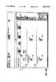
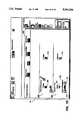
- FIG. 11is a chart showing a likely set of potential orientations for signatures such as Calendars and Books.
- Column 1gives a set of example output print copy sheet sizes (with size given as process direction length ⁇ cross process direction length).
- Column 2describes how those copy sheets travel through a reproduction device such as the Xerox Docutech Publishing System, with arrows 400(a)-(d) showing the direction of travel of the sheets in the process direction.
- Column 4shows the orientation of images placed on the copy sheets (output prints) if the input images are oriented at 0°.
- Column 5shows how the printed stock is usually used, which for example, for 17 ⁇ 11 calendar output prints, will be incorrect. Accordingly, Column 6 shows the required rotations. It will no doubt be appreciated that constraints may be placed on rotation based on this chart, and the combination of information about 1) sheet size; 2) signature format, and whether the sheet is long edge first or short edge first.
Landscapes
- Engineering & Computer Science (AREA)
- Physics & Mathematics (AREA)
- General Physics & Mathematics (AREA)
- Theoretical Computer Science (AREA)
- Multimedia (AREA)
- Signal Processing (AREA)
- Editing Of Facsimile Originals (AREA)
- Record Information Processing For Printing (AREA)
Abstract
Description
Claims (9)
Priority Applications (1)
| Application Number | Priority Date | Filing Date | Title |
|---|---|---|---|
| US07/862,916US5301036A (en) | 1992-04-06 | 1992-04-06 | Image orientation control |
Applications Claiming Priority (1)
| Application Number | Priority Date | Filing Date | Title |
|---|---|---|---|
| US07/862,916US5301036A (en) | 1992-04-06 | 1992-04-06 | Image orientation control |
Publications (1)
| Publication Number | Publication Date |
|---|---|
| US5301036Atrue US5301036A (en) | 1994-04-05 |
Family
ID=25339733
Family Applications (1)
| Application Number | Title | Priority Date | Filing Date |
|---|---|---|---|
| US07/862,916Expired - LifetimeUS5301036A (en) | 1992-04-06 | 1992-04-06 | Image orientation control |
Country Status (1)
| Country | Link |
|---|---|
| US (1) | US5301036A (en) |
Cited By (61)
| Publication number | Priority date | Publication date | Assignee | Title |
|---|---|---|---|---|
| US5461459A (en)* | 1993-08-02 | 1995-10-24 | Minolta Co., Ltd. | Digital copying apparatus capable of forming a binding at an appropriate position |
| US5508810A (en)* | 1991-10-17 | 1996-04-16 | Ricoh Company, Ltd. | Image recorder for properly orienting output images |
| US5526137A (en)* | 1993-01-11 | 1996-06-11 | Fuji Xerox Co., Ltd. | Image processing system and diagnosing method thereof |
| US5530517A (en)* | 1995-01-09 | 1996-06-25 | Eastman Kodak Company | Method for communicating scene orientation of camera film to photo finishing equipment |
| US5600429A (en)* | 1992-02-24 | 1997-02-04 | Canon Kabushiki Kaisha | Image copying apparatus |
| US5625466A (en)* | 1994-03-04 | 1997-04-29 | Minolta Co., Ltd. | Image forming apparatus providing landscape or portrait image format based on detected size of original |
| US5627650A (en)* | 1993-09-24 | 1997-05-06 | Kabushiki Kaisha Toshiba | Image forming apparatus having electronic sorting by image rotation |
| US5638181A (en)* | 1993-07-05 | 1997-06-10 | Ricoh Company, Ltd. | Duplex copier capable of digitally rotating an image on at least one side of a duplex copy sheet |
| US5694486A (en)* | 1994-02-07 | 1997-12-02 | Canon Kabushiki Kaisha | Image processing apparatus and method for designating one of a plurality of operating modes |
| GB2313728A (en)* | 1996-05-30 | 1997-12-03 | Eastman Kodak Co | Multiple page printing |
| WO1997050243A1 (en)* | 1996-06-25 | 1997-12-31 | Casio Computer Co., Ltd. | Printing apparatus and printing system |
| EP0791862A3 (en)* | 1996-02-26 | 1998-05-06 | Kabushiki Kaisha Toshiba | Image data processor |
| US5768488A (en)* | 1995-02-24 | 1998-06-16 | International Business Machines Corporation | Enhanced page placement for multiple-up presentation |
| US5790768A (en)* | 1992-07-24 | 1998-08-04 | Francotyp-Postalia Ag & Co. | Process and configuration for an internal cost accounting printout |
| NL1006250C2 (en)* | 1997-06-06 | 1998-12-08 | Oce Tech Bv | Digital image reproduction device with virtual copy sheet reservoir. |
| US5857209A (en)* | 1996-04-02 | 1999-01-05 | R. R. Donnelley & Sons Company | Efficient imposition of arbitrary postscript® files without preprocessing by defining a virtual device that specifies a desired position of a page on an output device while redefining postscript save and restore operators |
| US5875035A (en)* | 1995-11-13 | 1999-02-23 | Minolta Co., Ltd. | Image processing device with original image determination means |
| US5896202A (en)* | 1995-08-02 | 1999-04-20 | Canon Kabushiki Kaisha | Information processing apparatus and method for rotating an image based on an intended process |
| US5930005A (en)* | 1992-09-25 | 1999-07-27 | Canon Kabushiki Kaisha | Facsimile apparatus |
| EP0830011A3 (en)* | 1996-09-13 | 1999-07-28 | Eastman Kodak Company | A computer program product for selectively displaying an image positioned in a frame |
| US6088710A (en)* | 1997-10-29 | 2000-07-11 | R.R. Donnelley & Sons Company | Apparatus and method for producing fulfillment pieces on demand in a variable imaging system |
| US6137905A (en)* | 1995-08-31 | 2000-10-24 | Canon Kabushiki Kaisha | System for discriminating document orientation |
| US6148119A (en)* | 1995-02-01 | 2000-11-14 | Canon Kabushiki Kaisha | Character recognition in input images divided into areas |
| US6151423A (en)* | 1998-03-04 | 2000-11-21 | Canon Kabushiki Kaisha | Character recognition with document orientation determination |
| US6205452B1 (en) | 1997-10-29 | 2001-03-20 | R. R. Donnelley & Sons Company | Method of reproducing variable graphics in a variable imaging system |
| US6246993B1 (en) | 1997-10-29 | 2001-06-12 | R. R. Donnelly & Sons Company | Reorder system for use with an electronic printing press |
| US6275622B1 (en)* | 1998-06-30 | 2001-08-14 | Canon Kabushiki Kaisha | Image rotation system |
| US20010026379A1 (en)* | 2000-03-22 | 2001-10-04 | Collard Rene Francois Albert | Determination of image orientation in a digital copying apparatus |
| US6314213B1 (en)* | 1996-09-19 | 2001-11-06 | Canon Kabushiki Kaisha | Image processing apparatus and method which process image on the basis of direction of document |
| US20010051964A1 (en)* | 1995-06-07 | 2001-12-13 | R.R. Donnelley & Sons Company | Imposition process and apparatus for variable imaging system |
| US6332149B1 (en) | 1995-06-07 | 2001-12-18 | R. R. Donnelley & Sons | Imposition process and apparatus for variable imaging system |
| US6336011B1 (en)* | 1998-04-06 | 2002-01-01 | Canon Kabushiki Kaisha | Sheet binding system for an image forming apparatus |
| US6360028B1 (en)* | 1996-12-27 | 2002-03-19 | Canon Kabushiki Kaisha | Image processing apparatus and method |
| US6369915B1 (en)* | 1995-02-22 | 2002-04-09 | Canon Kabushiki Kaisha | Image processing apparatus for rotating an input image |
| US6411400B1 (en)* | 1998-07-14 | 2002-06-25 | Canon Kabushiki Kaisha | Data processing apparatus, data processing method therefor, and storage medium for storing computer-readable program |
| US20030008040A1 (en)* | 1996-01-08 | 2003-01-09 | Ajinomoto Co., Inc. | Edible microcapsule and food containing the same |
| US6633393B1 (en)* | 1998-12-10 | 2003-10-14 | Seiko Epson Coprporation | Printer, a control method therefor, and a control method storage medium |
| US20040012818A1 (en)* | 2002-07-19 | 2004-01-22 | Bauer Stephen W. | Reducing artifacts in printing |
| US6697091B1 (en)* | 2000-01-19 | 2004-02-24 | Xerox Corporation | Systems, methods and graphical user interfaces for indicating a desired original document orientation for image capture devices |
| US6741270B1 (en)* | 2000-01-19 | 2004-05-25 | Xerox Corporation | Systems and methods scaling a captured image using predetermined scale information |
| EP1469668A2 (en)* | 2003-04-15 | 2004-10-20 | Sony Corporation | Print terminal, print system and storage medium |
| US6850259B1 (en)* | 2000-01-19 | 2005-02-01 | Xerox Corporation | Systems and methods for providing original document orientation, tone reproduction curves and task specific user instructions based on displayed portions of a graphical user interface |
| US6885478B1 (en)* | 1999-11-23 | 2005-04-26 | Xerox Corporation | Image transfer device with automatic image adjustment |
| US20050105116A1 (en)* | 2003-11-13 | 2005-05-19 | Canon Kabushiki Kaisha | Document processing apparatus and document processing method |
| US20050105947A1 (en)* | 2003-11-17 | 2005-05-19 | Kim So-Hye | Method of indicating a paper insertion direction and a printer driver using the same |
| US20050254105A1 (en)* | 2004-05-17 | 2005-11-17 | Xerox Corporation | Image scanning apparatus that scans both sides of an input sheet |
| US20050280835A1 (en)* | 2004-06-17 | 2005-12-22 | Debusschere Eric T | Mouse support for a printing device |
| US7065716B1 (en)* | 2000-01-19 | 2006-06-20 | Xerox Corporation | Systems, methods and graphical user interfaces for previewing image capture device output results |
| US20070014611A1 (en)* | 2005-07-15 | 2007-01-18 | Konica Minolta Business Technologies, Inc. | Image forming system, image forming method and image forming program |
| US20070211262A1 (en)* | 2006-03-09 | 2007-09-13 | Kabushiki Kaisha Toshiba | Image forming apparatus |
| US7278094B1 (en) | 2000-05-03 | 2007-10-02 | R. R. Donnelley & Sons Co. | Variable text processing for an electronic press |
| US20090009788A1 (en)* | 2007-07-04 | 2009-01-08 | Yuki Mizobuchi | Image processing apparatus |
| US20090207435A1 (en)* | 2008-02-15 | 2009-08-20 | Kabushiki Kaisha Toshiba | Image scanning apparatus, image forming apparatus and image scanning method |
| US7609228B1 (en) | 2003-01-28 | 2009-10-27 | Pixelworks, Inc. | Automatic keystone correction system and method |
| US20100079821A1 (en)* | 2008-09-30 | 2010-04-01 | Oki Data Corporation | Image processing device and method of the same |
| US20100123928A1 (en)* | 2008-11-17 | 2010-05-20 | Atsuhisa Morimoto | Image processing apparatus, image forming apparatus, image processing method, and recording medium |
| US20100316295A1 (en)* | 2009-06-15 | 2010-12-16 | Atsuhisa Morimoto | Image processing method, image processing apparatus, image forming apparatus, and storage medium |
| US20110235118A1 (en)* | 2009-01-05 | 2011-09-29 | Gideon Amir | Printing method using a dual-engine printing system |
| US20130033731A1 (en)* | 2008-06-23 | 2013-02-07 | Sharp Kabushiki Kaisha | Image processing apparatus, image forming apparatus, image processing method, and storage medium |
| US20150047524A1 (en)* | 2012-02-21 | 2015-02-19 | Cristian Todie | Method for creating designs and raised patterns on the folds, recessed portions, and edge surfaces of objects consisting of sheets |
| US9679356B2 (en) | 2015-03-19 | 2017-06-13 | Xerox Corporation | Vectorized two stage tile-based scaling |
Citations (11)
| Publication number | Priority date | Publication date | Assignee | Title |
|---|---|---|---|---|
| JPS58222382A (en)* | 1982-06-18 | 1983-12-24 | Ricoh Co Ltd | Image tilt correction method |
| JPS5923670A (en)* | 1982-07-29 | 1984-02-07 | Yokogawa Hokushin Electric Corp | Tilt correction method when inputting digital images |
| US4754269A (en)* | 1984-03-05 | 1988-06-28 | Fanuc Ltd | Graphic display method for displaying a perspective view of an object on a CRT |
| US4929085A (en)* | 1986-09-30 | 1990-05-29 | Kabushiki Kaisha Toshiba | Image data rotation processing method and apparatus therefor |
| US4947344A (en)* | 1986-09-12 | 1990-08-07 | International Business Machines Corporation | Method of rotating image data in a partitioned display buffer |
| US5001574A (en)* | 1982-10-08 | 1991-03-19 | Canon Kabushiki Kaisha | Image processing system |
| US5021976A (en)* | 1988-11-14 | 1991-06-04 | Microelectronics And Computer Technology Corporation | Method and system for generating dynamic, interactive visual representations of information structures within a computer |
| US5038218A (en)* | 1990-10-10 | 1991-08-06 | Fuji Xerox Co., Ltd. | Image processing assembly with conversion and rotation of input image data or predetermined data to match data resolution and orientation |
| US5050225A (en)* | 1989-04-28 | 1991-09-17 | International Business Machines Corporation | Image processing apparatus and method |
| US5075785A (en)* | 1987-03-03 | 1991-12-24 | Canon Kk | mage processing apparatus |
| US5204916A (en)* | 1991-08-06 | 1993-04-20 | Eastman Kodak Company | Tile-oriented technique for collectively performing image rotation, scaling and digital halftone screening |
- 1992
- 1992-04-06USUS07/862,916patent/US5301036A/ennot_activeExpired - Lifetime
Patent Citations (11)
| Publication number | Priority date | Publication date | Assignee | Title |
|---|---|---|---|---|
| JPS58222382A (en)* | 1982-06-18 | 1983-12-24 | Ricoh Co Ltd | Image tilt correction method |
| JPS5923670A (en)* | 1982-07-29 | 1984-02-07 | Yokogawa Hokushin Electric Corp | Tilt correction method when inputting digital images |
| US5001574A (en)* | 1982-10-08 | 1991-03-19 | Canon Kabushiki Kaisha | Image processing system |
| US4754269A (en)* | 1984-03-05 | 1988-06-28 | Fanuc Ltd | Graphic display method for displaying a perspective view of an object on a CRT |
| US4947344A (en)* | 1986-09-12 | 1990-08-07 | International Business Machines Corporation | Method of rotating image data in a partitioned display buffer |
| US4929085A (en)* | 1986-09-30 | 1990-05-29 | Kabushiki Kaisha Toshiba | Image data rotation processing method and apparatus therefor |
| US5075785A (en)* | 1987-03-03 | 1991-12-24 | Canon Kk | mage processing apparatus |
| US5021976A (en)* | 1988-11-14 | 1991-06-04 | Microelectronics And Computer Technology Corporation | Method and system for generating dynamic, interactive visual representations of information structures within a computer |
| US5050225A (en)* | 1989-04-28 | 1991-09-17 | International Business Machines Corporation | Image processing apparatus and method |
| US5038218A (en)* | 1990-10-10 | 1991-08-06 | Fuji Xerox Co., Ltd. | Image processing assembly with conversion and rotation of input image data or predetermined data to match data resolution and orientation |
| US5204916A (en)* | 1991-08-06 | 1993-04-20 | Eastman Kodak Company | Tile-oriented technique for collectively performing image rotation, scaling and digital halftone screening |
Cited By (85)
| Publication number | Priority date | Publication date | Assignee | Title |
|---|---|---|---|---|
| US5508810A (en)* | 1991-10-17 | 1996-04-16 | Ricoh Company, Ltd. | Image recorder for properly orienting output images |
| US5600429A (en)* | 1992-02-24 | 1997-02-04 | Canon Kabushiki Kaisha | Image copying apparatus |
| US5790768A (en)* | 1992-07-24 | 1998-08-04 | Francotyp-Postalia Ag & Co. | Process and configuration for an internal cost accounting printout |
| US5930005A (en)* | 1992-09-25 | 1999-07-27 | Canon Kabushiki Kaisha | Facsimile apparatus |
| US5526137A (en)* | 1993-01-11 | 1996-06-11 | Fuji Xerox Co., Ltd. | Image processing system and diagnosing method thereof |
| US5638181A (en)* | 1993-07-05 | 1997-06-10 | Ricoh Company, Ltd. | Duplex copier capable of digitally rotating an image on at least one side of a duplex copy sheet |
| US5461459A (en)* | 1993-08-02 | 1995-10-24 | Minolta Co., Ltd. | Digital copying apparatus capable of forming a binding at an appropriate position |
| US5627650A (en)* | 1993-09-24 | 1997-05-06 | Kabushiki Kaisha Toshiba | Image forming apparatus having electronic sorting by image rotation |
| US5694486A (en)* | 1994-02-07 | 1997-12-02 | Canon Kabushiki Kaisha | Image processing apparatus and method for designating one of a plurality of operating modes |
| US5625466A (en)* | 1994-03-04 | 1997-04-29 | Minolta Co., Ltd. | Image forming apparatus providing landscape or portrait image format based on detected size of original |
| US5694634A (en)* | 1995-01-09 | 1997-12-02 | Eastman Kodak Company | Method for communicating scene orientation of camera film to photo finishing equipment |
| US5530517A (en)* | 1995-01-09 | 1996-06-25 | Eastman Kodak Company | Method for communicating scene orientation of camera film to photo finishing equipment |
| US6148119A (en)* | 1995-02-01 | 2000-11-14 | Canon Kabushiki Kaisha | Character recognition in input images divided into areas |
| US6369915B1 (en)* | 1995-02-22 | 2002-04-09 | Canon Kabushiki Kaisha | Image processing apparatus for rotating an input image |
| US5768488A (en)* | 1995-02-24 | 1998-06-16 | International Business Machines Corporation | Enhanced page placement for multiple-up presentation |
| US6332149B1 (en) | 1995-06-07 | 2001-12-18 | R. R. Donnelley & Sons | Imposition process and apparatus for variable imaging system |
| US6844940B2 (en) | 1995-06-07 | 2005-01-18 | Rr Donnelley & Sons Company | Imposition process and apparatus for variable imaging system |
| US20040216046A1 (en)* | 1995-06-07 | 2004-10-28 | R.R. Donnelley & Sons Company | Imposition process and apparatus for variable imaging system |
| US6952801B2 (en) | 1995-06-07 | 2005-10-04 | R.R. Donnelley | Book assembly process and apparatus for variable imaging system |
| US20010051964A1 (en)* | 1995-06-07 | 2001-12-13 | R.R. Donnelley & Sons Company | Imposition process and apparatus for variable imaging system |
| US5896202A (en)* | 1995-08-02 | 1999-04-20 | Canon Kabushiki Kaisha | Information processing apparatus and method for rotating an image based on an intended process |
| US6137905A (en)* | 1995-08-31 | 2000-10-24 | Canon Kabushiki Kaisha | System for discriminating document orientation |
| US5875035A (en)* | 1995-11-13 | 1999-02-23 | Minolta Co., Ltd. | Image processing device with original image determination means |
| US20030008040A1 (en)* | 1996-01-08 | 2003-01-09 | Ajinomoto Co., Inc. | Edible microcapsule and food containing the same |
| EP0791862A3 (en)* | 1996-02-26 | 1998-05-06 | Kabushiki Kaisha Toshiba | Image data processor |
| US5857209A (en)* | 1996-04-02 | 1999-01-05 | R. R. Donnelley & Sons Company | Efficient imposition of arbitrary postscript® files without preprocessing by defining a virtual device that specifies a desired position of a page on an output device while redefining postscript save and restore operators |
| US6175846B1 (en) | 1996-04-02 | 2001-01-16 | R. R. Donnelley & Sons Company | Efficient imposition of arbitrary postscript files without preprocessing |
| GB2313728B (en)* | 1996-05-30 | 2000-11-08 | Eastman Kodak Co | Apparatus and method for production of signatures |
| US5808747A (en)* | 1996-05-30 | 1998-09-15 | Eastman Kodak Company | Apparatus and method for production of signatures |
| GB2313728A (en)* | 1996-05-30 | 1997-12-03 | Eastman Kodak Co | Multiple page printing |
| WO1997050243A1 (en)* | 1996-06-25 | 1997-12-31 | Casio Computer Co., Ltd. | Printing apparatus and printing system |
| EP0830011A3 (en)* | 1996-09-13 | 1999-07-28 | Eastman Kodak Company | A computer program product for selectively displaying an image positioned in a frame |
| US6314213B1 (en)* | 1996-09-19 | 2001-11-06 | Canon Kabushiki Kaisha | Image processing apparatus and method which process image on the basis of direction of document |
| US6360028B1 (en)* | 1996-12-27 | 2002-03-19 | Canon Kabushiki Kaisha | Image processing apparatus and method |
| NL1006250C2 (en)* | 1997-06-06 | 1998-12-08 | Oce Tech Bv | Digital image reproduction device with virtual copy sheet reservoir. |
| US6236473B1 (en)* | 1997-06-06 | 2001-05-22 | Oce-Technologies B.V. | Digital image reproduction apparatus with a virtual copy sheet reservoir |
| EP0886434A1 (en)* | 1997-06-06 | 1998-12-23 | Océ-Technologies B.V. | Digital image reproduction apparatus with a virtual copy sheet reservoir |
| US6205452B1 (en) | 1997-10-29 | 2001-03-20 | R. R. Donnelley & Sons Company | Method of reproducing variable graphics in a variable imaging system |
| US6246993B1 (en) | 1997-10-29 | 2001-06-12 | R. R. Donnelly & Sons Company | Reorder system for use with an electronic printing press |
| US6088710A (en)* | 1997-10-29 | 2000-07-11 | R.R. Donnelley & Sons Company | Apparatus and method for producing fulfillment pieces on demand in a variable imaging system |
| US6151423A (en)* | 1998-03-04 | 2000-11-21 | Canon Kabushiki Kaisha | Character recognition with document orientation determination |
| US6336011B1 (en)* | 1998-04-06 | 2002-01-01 | Canon Kabushiki Kaisha | Sheet binding system for an image forming apparatus |
| US6275622B1 (en)* | 1998-06-30 | 2001-08-14 | Canon Kabushiki Kaisha | Image rotation system |
| US6411400B1 (en)* | 1998-07-14 | 2002-06-25 | Canon Kabushiki Kaisha | Data processing apparatus, data processing method therefor, and storage medium for storing computer-readable program |
| US6633393B1 (en)* | 1998-12-10 | 2003-10-14 | Seiko Epson Coprporation | Printer, a control method therefor, and a control method storage medium |
| US6885478B1 (en)* | 1999-11-23 | 2005-04-26 | Xerox Corporation | Image transfer device with automatic image adjustment |
| US6697091B1 (en)* | 2000-01-19 | 2004-02-24 | Xerox Corporation | Systems, methods and graphical user interfaces for indicating a desired original document orientation for image capture devices |
| US7065716B1 (en)* | 2000-01-19 | 2006-06-20 | Xerox Corporation | Systems, methods and graphical user interfaces for previewing image capture device output results |
| US6850259B1 (en)* | 2000-01-19 | 2005-02-01 | Xerox Corporation | Systems and methods for providing original document orientation, tone reproduction curves and task specific user instructions based on displayed portions of a graphical user interface |
| US6741270B1 (en)* | 2000-01-19 | 2004-05-25 | Xerox Corporation | Systems and methods scaling a captured image using predetermined scale information |
| US20010026379A1 (en)* | 2000-03-22 | 2001-10-04 | Collard Rene Francois Albert | Determination of image orientation in a digital copying apparatus |
| US7278094B1 (en) | 2000-05-03 | 2007-10-02 | R. R. Donnelley & Sons Co. | Variable text processing for an electronic press |
| US7949945B2 (en) | 2000-05-03 | 2011-05-24 | Rr Donnelley & Sons | Variable text processing for an electronic press |
| US20040012818A1 (en)* | 2002-07-19 | 2004-01-22 | Bauer Stephen W. | Reducing artifacts in printing |
| US7609228B1 (en) | 2003-01-28 | 2009-10-27 | Pixelworks, Inc. | Automatic keystone correction system and method |
| US7808513B1 (en)* | 2003-01-28 | 2010-10-05 | Pixelworks, Inc. | Automatic keystone correction system and method |
| US8269988B2 (en)* | 2003-04-15 | 2012-09-18 | Sony Corporation | Print terminal, print system, storage medium, and program |
| US20040252318A1 (en)* | 2003-04-15 | 2004-12-16 | Tatsuya Kuroda | Print terminal, print system, storage medium, and program |
| EP1469668A2 (en)* | 2003-04-15 | 2004-10-20 | Sony Corporation | Print terminal, print system and storage medium |
| US20050105116A1 (en)* | 2003-11-13 | 2005-05-19 | Canon Kabushiki Kaisha | Document processing apparatus and document processing method |
| US20050105947A1 (en)* | 2003-11-17 | 2005-05-19 | Kim So-Hye | Method of indicating a paper insertion direction and a printer driver using the same |
| US7248809B2 (en)* | 2003-11-17 | 2007-07-24 | Samsung Electronics Co., Ltd. | Method of indicating a paper insertion direction and a printer driver using the same |
| US20050254105A1 (en)* | 2004-05-17 | 2005-11-17 | Xerox Corporation | Image scanning apparatus that scans both sides of an input sheet |
| US7511864B2 (en)* | 2004-05-17 | 2009-03-31 | Xerox Corporation | Image scanning apparatus that scans both sides of an input sheet |
| US20050280835A1 (en)* | 2004-06-17 | 2005-12-22 | Debusschere Eric T | Mouse support for a printing device |
| US20070014611A1 (en)* | 2005-07-15 | 2007-01-18 | Konica Minolta Business Technologies, Inc. | Image forming system, image forming method and image forming program |
| US8115961B2 (en)* | 2005-07-15 | 2012-02-14 | Konica Minolta Business Technologies, Inc. | Method and apparatus providing consistent rotation for pages in a job in accordance with post-processing requirements |
| US7782497B2 (en)* | 2006-03-09 | 2010-08-24 | Kabushiki Kaisha Toshiba | Image forming apparatus that displays icons in a selectable state according to draft setting direction |
| US20070211262A1 (en)* | 2006-03-09 | 2007-09-13 | Kabushiki Kaisha Toshiba | Image forming apparatus |
| US20110007335A1 (en)* | 2006-03-09 | 2011-01-13 | Kabushiki Kaisha Toshiba | Image forming apparatus that displays icons in a selectable state according to draft setting direction |
| US8054480B2 (en)* | 2007-07-04 | 2011-11-08 | Sharp Kabushiki Kaisha | Image processing apparatus |
| US20090009788A1 (en)* | 2007-07-04 | 2009-01-08 | Yuki Mizobuchi | Image processing apparatus |
| US20090207435A1 (en)* | 2008-02-15 | 2009-08-20 | Kabushiki Kaisha Toshiba | Image scanning apparatus, image forming apparatus and image scanning method |
| US8203763B2 (en)* | 2008-02-15 | 2012-06-19 | Kabushiki Kaisha Toshiba | Image scanning apparatus and method for aligning a stack of scanned images using the stack orientation indicated by a user and an automatically determined image orientation |
| US20130033731A1 (en)* | 2008-06-23 | 2013-02-07 | Sharp Kabushiki Kaisha | Image processing apparatus, image forming apparatus, image processing method, and storage medium |
| US8537443B2 (en)* | 2008-06-23 | 2013-09-17 | Sharp Kabushiki Kaisha | Image processing apparatus, image forming apparatus, image processing method, and storage medium |
| US20100079821A1 (en)* | 2008-09-30 | 2010-04-01 | Oki Data Corporation | Image processing device and method of the same |
| US8462396B2 (en)* | 2008-09-30 | 2013-06-11 | Oki Data Corporation | Image processing device and method for rotating a scanned image |
| US20100123928A1 (en)* | 2008-11-17 | 2010-05-20 | Atsuhisa Morimoto | Image processing apparatus, image forming apparatus, image processing method, and recording medium |
| US20110235118A1 (en)* | 2009-01-05 | 2011-09-29 | Gideon Amir | Printing method using a dual-engine printing system |
| US20100316295A1 (en)* | 2009-06-15 | 2010-12-16 | Atsuhisa Morimoto | Image processing method, image processing apparatus, image forming apparatus, and storage medium |
| US8532434B2 (en)* | 2009-06-15 | 2013-09-10 | Sharp Kabushiki Kaisha | Image processing method and apparatus for determining orientations based on reliabilities of a plurality of portions into which image has been divided or for determining orientations of portions of image divided by user's input so as to recognize characters for each divided portion of image, image forming apparatus, and storage medium |
| US20150047524A1 (en)* | 2012-02-21 | 2015-02-19 | Cristian Todie | Method for creating designs and raised patterns on the folds, recessed portions, and edge surfaces of objects consisting of sheets |
| US10759161B2 (en)* | 2012-02-21 | 2020-09-01 | Cristian Todie | Method for creating designs and raised patterns on the folds, recessed portions, and edge surfaces of objects consisting of sheets |
| US9679356B2 (en) | 2015-03-19 | 2017-06-13 | Xerox Corporation | Vectorized two stage tile-based scaling |
Similar Documents
| Publication | Publication Date | Title |
|---|---|---|
| US5301036A (en) | Image orientation control | |
| US5260805A (en) | Process for identifying programming conflicts in electronic printing systems | |
| EP0606131B1 (en) | Method for compiling multiple jobs with job reference sheets | |
| EP1257894B1 (en) | Method and apparatus for tab printing | |
| EP0478970B1 (en) | An electronic printing process for printing multiple up images | |
| US5398289A (en) | Process for programming and producing one or more signature prints in an electronic printing system | |
| US5337161A (en) | Tab image extraction and placement | |
| US5521710A (en) | Method of applying electronically stored labels from a source job to a destination job in a printing system | |
| US5631747A (en) | Apparatus and method for applying trim marks to a print media sheet | |
| US5119206A (en) | System for printing bound documents | |
| AU2001239868A1 (en) | Method and apparatus for tab printing | |
| EP0507562A2 (en) | Process for electronically printing envelopes | |
| EP0479494A2 (en) | Process for printing ordered stock | |
| US6151131A (en) | Print system with deferred job assembly feature | |
| US5309558A (en) | Set addressing for electronic printing machines | |
| EP0476964B1 (en) | Method and apparatus for scanning a signature document | |
| US5450541A (en) | Method of applying electronically stored labels to a print job | |
| EP0461920B1 (en) | Printing systems | |
| EP0488814B1 (en) | System for scanning signature pages | |
| EP0478351A2 (en) | Page number generation and formatting in electronic reprographic/printing products | |
| US5832193A (en) | Method and apparatus for printing a label on the spine of a bound document | |
| EP0478335A2 (en) | Electronic printing system |
Legal Events
| Date | Code | Title | Description |
|---|---|---|---|
| AS | Assignment | Owner name:XEROX CORPORATION A CORPORATION OF NEW YORK Free format text:ASSIGNMENT OF ASSIGNORS INTEREST.;ASSIGNORS:BARRETT, MICHAEL W.;SMITH, CYNTHIA A.;PARSONS THOMAS, CAROL P.;AND OTHERS;REEL/FRAME:006081/0712 Effective date:19920331 | |
| STCF | Information on status: patent grant | Free format text:PATENTED CASE | |
| FPAY | Fee payment | Year of fee payment:4 | |
| FPAY | Fee payment | Year of fee payment:8 | |
| AS | Assignment | Owner name:BANK ONE, NA, AS ADMINISTRATIVE AGENT, ILLINOIS Free format text:SECURITY INTEREST;ASSIGNOR:XEROX CORPORATION;REEL/FRAME:013153/0001 Effective date:20020621 | |
| AS | Assignment | Owner name:JPMORGAN CHASE BANK, AS COLLATERAL AGENT, TEXAS Free format text:SECURITY AGREEMENT;ASSIGNOR:XEROX CORPORATION;REEL/FRAME:015134/0476 Effective date:20030625 Owner name:JPMORGAN CHASE BANK, AS COLLATERAL AGENT,TEXAS Free format text:SECURITY AGREEMENT;ASSIGNOR:XEROX CORPORATION;REEL/FRAME:015134/0476 Effective date:20030625 | |
| FPAY | Fee payment | Year of fee payment:12 | |
| AS | Assignment | Owner name:XEROX CORPORATION, CONNECTICUT Free format text:RELEASE BY SECURED PARTY;ASSIGNOR:JPMORGAN CHASE BANK, N.A. AS SUCCESSOR-IN-INTEREST ADMINISTRATIVE AGENT AND COLLATERAL AGENT TO JPMORGAN CHASE BANK;REEL/FRAME:066728/0193 Effective date:20220822 |