US5301010A - Interferometer having a short coherence length light source and means for identifying interference fringes - Google Patents
Interferometer having a short coherence length light source and means for identifying interference fringesDownload PDFInfo
- Publication number
- US5301010A US5301010AUS07/752,612US75261291AUS5301010AUS 5301010 AUS5301010 AUS 5301010AUS 75261291 AUS75261291 AUS 75261291AUS 5301010 AUS5301010 AUS 5301010A
- Authority
- US
- United States
- Prior art keywords
- fringes
- series
- interferometer
- signal
- mirror
- Prior art date
- Legal status (The legal status is an assumption and is not a legal conclusion. Google has not performed a legal analysis and makes no representation as to the accuracy of the status listed.)
- Expired - Fee Related
Links
Images


Classifications
- G—PHYSICS
- G01—MEASURING; TESTING
- G01B—MEASURING LENGTH, THICKNESS OR SIMILAR LINEAR DIMENSIONS; MEASURING ANGLES; MEASURING AREAS; MEASURING IRREGULARITIES OF SURFACES OR CONTOURS
- G01B9/00—Measuring instruments characterised by the use of optical techniques
- G01B9/02—Interferometers
- G01B9/02001—Interferometers characterised by controlling or generating intrinsic radiation properties
- G01B9/0201—Interferometers characterised by controlling or generating intrinsic radiation properties using temporal phase variation
- G—PHYSICS
- G01—MEASURING; TESTING
- G01B—MEASURING LENGTH, THICKNESS OR SIMILAR LINEAR DIMENSIONS; MEASURING ANGLES; MEASURING AREAS; MEASURING IRREGULARITIES OF SURFACES OR CONTOURS
- G01B9/00—Measuring instruments characterised by the use of optical techniques
- G01B9/02—Interferometers
- G01B9/02015—Interferometers characterised by the beam path configuration
- G01B9/02027—Two or more interferometric channels or interferometers
- G01B9/02028—Two or more reference or object arms in one interferometer
- G—PHYSICS
- G01—MEASURING; TESTING
- G01B—MEASURING LENGTH, THICKNESS OR SIMILAR LINEAR DIMENSIONS; MEASURING ANGLES; MEASURING AREAS; MEASURING IRREGULARITIES OF SURFACES OR CONTOURS
- G01B9/00—Measuring instruments characterised by the use of optical techniques
- G01B9/02—Interferometers
- G01B9/02055—Reduction or prevention of errors; Testing; Calibration
- G01B9/02056—Passive reduction of errors
- G01B9/02057—Passive reduction of errors by using common path configuration, i.e. reference and object path almost entirely overlapping
- G—PHYSICS
- G01—MEASURING; TESTING
- G01B—MEASURING LENGTH, THICKNESS OR SIMILAR LINEAR DIMENSIONS; MEASURING ANGLES; MEASURING AREAS; MEASURING IRREGULARITIES OF SURFACES OR CONTOURS
- G01B9/00—Measuring instruments characterised by the use of optical techniques
- G01B9/02—Interferometers
- G01B9/02055—Reduction or prevention of errors; Testing; Calibration
- G01B9/02062—Active error reduction, i.e. varying with time
- G01B9/02064—Active error reduction, i.e. varying with time by particular adjustment of coherence gate, i.e. adjusting position of zero path difference in low coherence interferometry
- G01B9/02065—Active error reduction, i.e. varying with time by particular adjustment of coherence gate, i.e. adjusting position of zero path difference in low coherence interferometry using a second interferometer before or after measuring interferometer
- G—PHYSICS
- G01—MEASURING; TESTING
- G01B—MEASURING LENGTH, THICKNESS OR SIMILAR LINEAR DIMENSIONS; MEASURING ANGLES; MEASURING AREAS; MEASURING IRREGULARITIES OF SURFACES OR CONTOURS
- G01B9/00—Measuring instruments characterised by the use of optical techniques
- G01B9/02—Interferometers
- G01B9/02055—Reduction or prevention of errors; Testing; Calibration
- G01B9/0207—Error reduction by correction of the measurement signal based on independently determined error sources, e.g. using a reference interferometer
- G01B9/02072—Error reduction by correction of the measurement signal based on independently determined error sources, e.g. using a reference interferometer by calibration or testing of interferometer
- G—PHYSICS
- G01—MEASURING; TESTING
- G01B—MEASURING LENGTH, THICKNESS OR SIMILAR LINEAR DIMENSIONS; MEASURING ANGLES; MEASURING AREAS; MEASURING IRREGULARITIES OF SURFACES OR CONTOURS
- G01B9/00—Measuring instruments characterised by the use of optical techniques
- G01B9/02—Interferometers
- G01B9/0209—Low-coherence interferometers
- G—PHYSICS
- G01—MEASURING; TESTING
- G01B—MEASURING LENGTH, THICKNESS OR SIMILAR LINEAR DIMENSIONS; MEASURING ANGLES; MEASURING AREAS; MEASURING IRREGULARITIES OF SURFACES OR CONTOURS
- G01B2290/00—Aspects of interferometers not specifically covered by any group under G01B9/02
- G01B2290/30—Grating as beam-splitter
- G—PHYSICS
- G01—MEASURING; TESTING
- G01B—MEASURING LENGTH, THICKNESS OR SIMILAR LINEAR DIMENSIONS; MEASURING ANGLES; MEASURING AREAS; MEASURING IRREGULARITIES OF SURFACES OR CONTOURS
- G01B2290/00—Aspects of interferometers not specifically covered by any group under G01B9/02
- G01B2290/45—Multiple detectors for detecting interferometer signals
Definitions
- This inventionrelates to interferometry and is particularly concerned with methods and apparatus for measuring or tracking variations in a parameter utilising interferometric techniques.
- the range of movement of the movable mirrorrepresents the range of values of the parameter which can be measured, it is necessary, if an absolute value for the parameter is required, to ensure that the mirror is first moved to one of its end positions and then to count fringes from that position, when setting up the apparatus. This is a disadvantage of conventional interferometers.
- the intensities of the bright and dark fringes, and therefore the contrast between those fringesremains substantially uniform as the movable mirror moves.
- a light source having a certain but limited bandwidthwere used instead of the monochromatic light source, the brightness of both the bright and dark fringes and the contrast between them would all vary as the movable mirror moves.
- the contrastwould be a maximum when the optical path length difference in the two arms of the interferometer is zero and would decrease with increasing optical path length difference (or phase difference) in the two arms.
- the brightness of the bright fringes and the darkness of the dark fringeswould be at a maximum when the optical path length difference in the two arms is at or near to zero.
- the contrast between the bright and dark fringeswould have decreased to an extent that the fringes become substantially invisible.
- One object of the inventionis to overcome these problems.
- the inventionprovides an interferometer and a method of interferometry in which a light source of relatively short coherence length is utilised to produce interference fringes having a parameter whose magnitude varies as a function of the variable to be measured, the magnitude of said parameter is detected, and a signal is derived from said magnitude to represent the value of the variable.
- the inventionprovides an interferometer or method of interferometry in which a relatively short coherence length light source is utilised to produce fringes having a contrast which varies as a function of the measurand and the signal representing said measurand is derived from said contrast.
- the inventionprovides an interferometer and a method of interferometry in which a set of interference fringes is produced in sequence as the measurand varies, the fringes in said set are distinguishable from each other and the particular fringe or fringes of the set are detected to provide an indication of the magnitude of the measurand.
- An alternative aspect of the inventionconcerns the problem that in certain applications it would be desirable to be able to make interferometric measurements in a hostile environment.
- a further aspect of the inventionprovides a measuring apparatus comprising an interferometric sensing head, a tracking interferometer and linkage means interconnecting said sensing head and said tracking interferometer for transmitting light from the sensing head to the tracking interferometer for the taking of interferometric measurements.
- the sensing headmay be constructed as a robust unit in order to withstand hostile environments.
- FIG. 1is a diagram of a simple interferometer and is included to assist in understanding the optical principles utilised in the preferred embodiment of the present invention
- FIG. 2is a diagram, not to scale, illustrating variations in light intensity which arise in a beam produced by the interferometer of FIG. 1 under certain conditions;
- FIG. 3is a diagram of a first preferred embodiment of the invention.
- FIG. 4is a graph to illustrate the operation of the apparatus of FIG. 3;
- FIGS. 5 (a-c)are a waveform diagram for understanding the operation of the embodiment of FIG. 3;
- FIG. 6is a block diagram showing part of the embodiment of FIG. 3 in more detail
- FIG. 7is a block diagram showing a modification to the embodiment of FIG. 3 to obtain higher resolution
- FIG. 8is a diagram of another embodiment of the invention.
- FIG. 9illustrates diagrammatically an embodiment of the invention for measuring surface profiles
- FIG. 10is a diagrammatic representation of a further embodiment
- FIG. 11illustrates a modification to the embodiment of FIG. 10
- FIG. 12is a diagrammatic representation of another embodiment
- FIG. 13is a diagrammatic representation of yet a further embodiment
- FIG. 14is a curve for illustrating the operation of the embodiment of FIG. 16;
- FIG. 15is a diagrammatic representation of another embodiment
- FIGS. 16 to 22are diagrams of sensing heads which may be incorporated into the embodiment of FIG. 10;
- FIG. 23is a diagrammatic representation of yet a further embodiment.
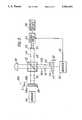
- FIG. 1shows a simple interferometer comprising a light source 2, a beam splitter 4 and two plane mirrors 6,8 which are arranged to reflect the split beams of light 10,12 back to the beam splitter 4 for recombination in a beam 14 which is directed to a detector or observer 16.
- the beams 10 and 12will constructively interfere on recombination and the detector or observer 16 will receive bright light in the beam 14. If one of the mirrors, say mirror 6, is moved away from the beam splitter 4, alternate destructive and constructive interference will arise upon recombination of the beams 10 and 12, assuming the movement is greater than the wavelength of light concerned, and the intensity of the light in the beam will alternate between high and low levels. Thus, the observer or detector 16 would alternately see a bright fringe followed by a dark fringe followed by a bright fringe etc.
- the intensity of the bright and dark fringes and the contrast between these fringeswill be substantially constant as the mirror 6 moves regardless of which direction it moves in and substantially regardless of the distance through which it is moved. Whilst counting these fringes would provide a measure of the distance through which the mirror has moved, without knowledge of the starting point it would not provide an indication of the actual position of the mirror.
- the light source 2were quasi-monochromatic, that is to say non-monochromatic but of limited bandwidth, whilst fringes would be produced, these would be of varying intensity and contrast. More particularly, a fringe of maximum brightness would be observed when the mirrors 6 and 8 are equidistant from the beam splitter 4 and a series of fringes of successively lower contrast would be observed as the distance through which the mirror 6 increases until, at some point dependent upon the bandwidth of the light, the contrast between the bright and dark fringes would become so low that the fringes would cease to be observable. This is illustrated in FIG.
- curve 18(which for clarity is only partly shown) represents the intensity of the light in beam 14 against the position of the mirror 6 when moved through a distance L and curve 20 is the envelope of the maxima in curve 18.
- portion 18b of curve 18illustrates the same effect if the mirror 6 were moved to the right from its centre position as shown in FIG. 1.
- the intensity of the bright fringes as indicated by the maxima in the curve 18decreases with increase in the distance through which the mirror 6 has moved from its centre position and simultaneously the intensity of the dark fringes, represented by the minima of curve 18, increases.
- the contrast between the bright and dark fringes as represented by the amplitude of curve 18decreases with increase in the distance through which the mirror 6 has moved from its centre position until as illustrated by portions 18c and 18d of curve 18 the amplitude of that curve becomes quite small and continued movement of the mirror no longer produces fringes which are easily observable.
- Curve 20 in FIG. 2thus comprises relatively steep portions 20a,20b, relatively flat outer portions 20c and 20d and a peak 20e.
- the contrast of the fringes represented in FIG. 2is representative of the path difference between mirrors 6 and 8 respectively and the beam splitter 4 and this fact is utilised in the preferred embodiment of the invention for obtaining an indication of the actual value of this path difference.
- a light source 30,such as a laser diode, directs non-monochromatic light of limited bandwidth of a beam splitter 32 which splits this light into first and second beams 34,36.
- a plane mirror 38reflects the beam 34 back to the beam splitter 32 and is coupled to a sensor 40 for sensing a parameter to be measured. As the parameter varies, the sensor causes mirror 38 to move towards or away from the beam splitter 32.
- the type of sensor and the means by which this movement is achievedare not described as they form no part of the present invention.
- the beam 36is reflected back to the beam splitter 32 by a mirror 42 which is stepped to provide reflective surfaces 44 and 46 at different distances from the beam splitter 32.
- the beam 36comprises two parts, indicated as 36a and 36b which have different phases as a result of having been reflected from the spaced surfaces 44 and 46.
- Recombination of the beam parts 36a and 36b with the beam 34 at the beam splitter 32produces two output beams 48 and 50 respectively.
- Light sensitive detectors D1 and D2receive the respective beams 48 and 50.
- Mirrors 38 and 42are arranged so that, as mirror 38 moves towards and away from beam splitter 32, interference fringes of varying contrast as described with reference to FIG. 2 are produced both in beam 48 and in beam 50.
- curve 54is the envelope of the intensity maxima of the fringes produced in beam 50
- curve 56is the envelope of the maxima of the fringes produced in beam 48, curves 54 and 56 each corresponding to curve 20 of FIG. 2.
- Curves 54 and 56are displaced relative to each other as a result of the presence of the step in mirror 42. This step height h is chosen so that, although curves 54 and 56 are displaced relative to each other, they overlap in the manner shown.
- curves 54 and 56 in FIG. 4comprise steep and relatively linear portions 54a,54b and 56a,56b, relatively flat portions 54d and 54c (the other relatively flat portions not being visible in FIG. 4) and peaks 54e and 56e.
- the sensor 40is arranged so that variation of the parameter sensed throughout the range to be measured causes movement of the mirror 38 through a distance S between end positions 38a and 38b as indicated in FIG. 3.
- the distance S and end positions 38a and 38bare chosen to correspond to the overlapping relatively linear steep portions 54b,56a of the envelope curves 54 and 56.
- the centre position 38c of the mirror 38is also indicated in both Figures.
- the position of the mirror 38acan be determined by determining the contrast of these fringes.
- the mirror 42is oscillated towards and away from the beam splitter 32 as indicated by double-headed arrow 60 in FIG. 3.
- the amplitude of the oscillationis equal to a few wavelengths of the light emitted by diode 30 (or more accurately a few wavelengths of the light at the centre of the band emitted by laser diode 30) so as to introduce an oscillating phase variation between both beam part 36a and beam 34 and beam part 36b and beam 34.
- the oscillation of mirror 42thus causes the intensity of each beam 48 and 50 to vary as constructive and destructive interference successively takes place, i.e. as bright and dark fringes successively appear.
- detectors D1 and D2will produce outputs with an alternating component whose amplitude is dependent upon the contrast in brightness between the bright and dark fringes.
- the amplitudes of the signals output by detectors D1 and D2will be respectively large and small and each output will be amplitude modulated in accordance with the corresponding portion of the respective envelope curve 54 or 56.
- diagram Ashows a portion of the curve 56 in the region of position 38d and also includes a curve 62 representing the intensity variation (i.e. the fringes) arising in beam 48 as the mirror 42 oscillates.
- the double-headed arrow 60is marked on FIG. 4 and FIG. 5 to represent the oscillation.
- the horizontal axis of the upper diagram (diagram A) in FIG. 5represents the instantaneous position of the mirror 42 as it oscillates and curve 62 is a plot of the intensity of beam 48 against the position of the mirror 42.
- Diagram B in FIG. 5is a plot of the magnitude of the output signal from detector D1 against time and diagram C in FIG. 5 is a plot of the position of oscillating mirror 42 against time.
- the amplitude of oscillation of mirror 42is such that, in each cycle, six fringes appear sequentially in each cycle. The maximum intensities of these six fringes are indicated as amax to fmax respectively and the minimum intensities of these fringes are designated as amin to emin (fmin being out of the range of oscillation of mirror 42).
- the end points of the oscillation of the mirror 42 in the example under discussioncoincide with positions somewhat to the left of amax and somewhat to the right of fmax respectively, these positions being designated by reference characters g and h respectively in FIG. 5A.
- the magnitude of the signal output by detector D1is shown in FIG. 5B.
- the signal output by detector D1varies according to the intensity of the light in beam 48 and the oscillating signal component from detector D1 has peaks corresponding to amax to fmax, troughs corresponding to amin to emin and intermediate values corresponding to points g and h shown in FIG. 5A, these values g and h appearing in signal B at times corresponding to the respective end positions of the oscillation of mirror 42 as illustrated by the curve in FIG. 5C.
- a driver 62for example a piezoelectric crystal device actuated by an alternating voltage, is coupled to the mirror 42 to effect the oscillation 60.
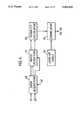
- a signal processor 64which may for example comprise a computer suitably programmed, receives the outputs from the detectors D1 and D2 and also receives on line 66 a signal from driver 62 which corresponds to waveform C in FIG. 5 and represents the oscillation of mirror 42. As seen in FIG.
- the signals from the detectors D1 and D2 and the driver 62are supplied to a data acquisition block 68 and, in this block, the signals may be digitised over a number of cycles of oscillation of the mirror 42, for example several tens or several hundreds of cycles, and the digitised signals stored for further processing.
- noise reductionis performed on the stored signals obtained in data acquisition block 68. This noise reduction is preferably achieved by the following routine:
- the values F1 to Fn and G1 to Gnrepresent the visibility of the fringes observed by detectors D1 and D2 as the mirror 42 oscillates and may be termed "visibility functions".
- the following calculationsare then performed in block 72: ##EQU3##
- H1 to Hnis a set of numbers which uniquely defines each of the possible positions of mirror 38 within its range of operation.
- the numbers H1 to Hn obtained in block 72are then correlated in block 74 with a single set of numbers representing all positions of the mirror 38 within the range S.
- the numbers of the look-up tablemay be derived in a setting up operation when the instrument is prepared for use. This operation may comprise driving the mirror 38 between its end positions by activating the sensor 4.
- the detectors D1 and D2would then (with the source 30 energised of course) produce sets of signals representing the brightness of the fringes as a function of the displacement throughout the range S.
- the mirror 38would be moved between its end positions and samples obtained a large number of times in order that noise reduction may be performed on the signals obtained.
- Visibility calculationswould then be performed on the two sets of noise reduced signals in the manner described above with reference to block 72 except that, in the setting up operation, visibility calculations for all of the fringes within the range S would be produced.
- the individual visibility functions obtained for detector D1would then be divided by the corresponding individual visibility functions obtained from detector D2 and the resulting ratios stored in the look-up table for correlation with H1 to Hn when the instrument is operated. This correlation may be achieved by comparing the numbers H1 to Hn with each successive group of n numbers in the look-up table to determine the best match.
- the number of comparisons performed to obtain the best matchwould then be an indication of the actual position of mirror 38 within its range S and this last-mentioned number may then be output to the output device 78 diagrammatically illustrated in FIG. 3, which device may for example be a printer or display or may alternatively simply be circuitry connected to some other electronic device which utilises the information obtained on the value of the parameter being sensed.
- a corresponding set of numbers indicating half-wavelength displacement in the range Swould, of course, be stored in the look-up table for comparison with the numbers obtained during the measurement operation.
- H'1 to H'nthe system would be highly tolerant to degradation and imperfections and would be particularly insensitive to, for example, variations in the power of the light source. This is because not only are the visibility functions F1 to Fn and G1 to Gn normalised but also further normalisation takes place in the calculation of H'1 to H'n.
- FIG. 7differs from FIG. 6 in that block 80 for sub-wavelength estimation is included and the output of this block is added to the output of correlator 74 in block 82, whose output is supplied to output device 78.
- block 80 for sub-wavelength estimationis included and the output of this block is added to the output of correlator 74 in block 82, whose output is supplied to output device 78.
- phase x of the mid-point 38d of the mirror oscillationcan be calculated to a sub-wavelength resolution from the mean values g and h in addition to the other phase and amplitude data.
- Thismay be achieved, by way of example, as follows: ##EQU5## where it will be recognised that h, g, amin, amax, emin, fmax derive from the fringe geometry at the points of turn round in the phase modulation (as illustrated in FIG. 5) and n corresponds to the fringe order derived from the coherence function measurement and correlation process defined by either H1 to Hn or H'1 to H'n.
- FIG. 8shows part of a further modified embodiment which comprises only two detectors D1 and D2 and in which signal processing may be as described with reference to FIGS. 3 to 7.
- the mirrors 38 and 42are dispensed with and replaced by corner cubes 102 and 104, one of which is connected to a sensor (not shown) and the other of which is vibrated by a driver which is also not shown but may be similar to driver 62. Since the stepped mirror 42 has been omitted, a stepped glass block 106 is included instead to create the required displacement in the coherence functions associated with beams 48 and 50 and as illustrated in FIG. 4.
- the advantage of the arrangement shown in FIG. 8is that the corner cubes are insensitive to alignment errors.
- FIG. 8shows in broken lines an alternative position for detector D1 which might in practice be employed if there is not sufficient room for the detectors D1 and D2 to be positioned next to each other.
- FIG. 9The application of the invention to the measurement of surface profile is illustrated in FIG. 9.
- the embodimentis similar to FIG. 3 except that mirror 38 is omitted and its function in the operation of the apparatus is performed by a surface 110 whose profile is to be measured. Accordingly, the surface 110 must be reflective.
- a lens 112is attached to the beam splitter 32 for focussing the beam 34 on the surface 110 and for collimating the light reflected back from that surface.
- the FIG. 12 embodimentis identical to that in FIG. 3 (although not all parts are shown in FIG. 12) and signal processing may be as described with reference to FIGS. 3 to 7.
- relative movement between the surface 110 and the device of the inventionis effected, which movement should be slow relative to the speed of oscillation of the mirror 42.
- the sensor 40may comprise a stylus which is drawn across the surface whose profile is to be measured and whose movement causes movement of the mirror 38 in accordance with surface profile.
- the arrangement shown in FIG. 3might be used to measure pressure by coupling the movable mirror 38 to a pressure responsive diaphragm, for example.
- a remote sensing head 200 of rugged constructionreceives light from a short coherence source 202 through a semi-reflective mirror 204 and an optical fibre link 206. After reflection in the sensing head 200, light is returned through the optical fibre link 206 to the mirror 204 and reflected into a tracking interferometer 208 whose construction is similar, but not identical, to the interferometer shown in FIG. 3 and is, therefore, in accordance with the present invention.
- the purpose of the arrangement shown in FIG. 10is to separate the sensing head from the tracking interferometer and to provide a sensing head which does not contain any active optical or electronic components but contains only passive optical elements which ma accordingly be highly resistant to hostile environments.
- the sensing head 200comprises a beam splitter 210, a fixed reference mirror 212 and a movable mirror 214 the position of which changes in response to the measurand.
- the optical path lengths between beam splitter 210 and the mirrors 212 and 214are respectively indicated as j and k and the difference between these two path lengths is arranged to be substantially greater than the coherence length of source 202.
- the tracking interferometer 208comprises a beam splitter 216, a fixed mirror 218, a stepped mirror 220 and detectors D1 and D2 which respectively receive light reflected from the surfaces 224 and 226 of the stepped mirror 220 after recombination with the beam reflected from mirror 218 and after reflection from mirrors 228 and 230.
- Mirror 60is oscillated by a driver (not shown but similar to driver 62 of FIG. 3) in the direction of double-headed arrow 60, the amplitude of oscillations being similar to the amplitude of the oscillations of mirror 42 in FIG. 3.
- the optical path length between beam splitter 216 and mirrors 220 and 218is designated in FIG. 13 respectively as n and m. These distances are chosen to satisfy the following relationships:
- Lhas the meaning indicated in FIG. 2 and may be termed the coherence length.
- detectors D1 and D2will produce output signals as described with reference to FIGS. 3 to 5 as the mirror 220 is oscillated in the same manner as mirror 42 and the signals thereby produced can be processed as described with reference to FIG. 6 or 7 to provide an indication of the position of mirror 214 within its range of movement and therefore to provide an indication of the magnitude of the parameter being measured.
- link 206has been described as an optical fibre link in FIG. 10, this could be omitted and instead light could be transmitted between mirror 204 and sensing head 200 through free space.
- FIG. 11shows a modification to the embodiment of FIG. 10 for surface profile measurement.
- the sensing head 200is replaced by a sensing head 231 which comprises a collimating lens 232, a focussing lens 234 for focussing light received from the lens 232 onto a surface 236 whose profile is to be measured and the semi-reflective surface 238 between the lenses 232 and 234 which serves the function of both the beam splitter 210 and the reference surface 212.
- a sensing head 231which comprises a collimating lens 232, a focussing lens 234 for focussing light received from the lens 232 onto a surface 236 whose profile is to be measured and the semi-reflective surface 238 between the lenses 232 and 234 which serves the function of both the beam splitter 210 and the reference surface 212.
- Reference number 239 in FIG. 11indicates diagrammatically such an end facet.
- the light reflected back to the optical fibre link 206is a combination of light reflected from the surface 238 (or 239) and the light reflected from the surface 236 and the distance between these two surfaces has to be substantially greater than the coherence length of source 202.
- the light from the short coherence source 202is split at a beam splitter 240 to form two beams 242 and 244.
- Beam 242passes through a phase modulator 246 and is recombined with beam 244 at a beam combiner 248, beam 244 having been passed to the combiner 248 by reflection at mirrors 250 and 252.
- the sensing head 200is as described with reference to FIG. 13 but the tracking interferometer 208 is modified in that both mirrors 218 and 220 are fixed and the phase modulator 246 is utilised instead of oscillating the mirror 220.
- the frequency and amplitude of the phase modulation produced by modulator 246may be equivalent to the frequency and amplitude of oscillation of mirror 220.
- elements 240, 246, 248, 250 and 252may all be formed as a single integrated optical device.
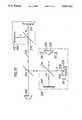
- light from a short coherence length source 260is transmitted through a beam combiner 262 to a beam splitter 264 to a fixed mirror 266 and a further mirror 268 movable in response to a measurand, these mirrors being spaced from the beam splitter 264 by the distances j and k whose difference, as previously described, is substantially greater than the coherence length of source 260.
- the recombined beams reflected from mirrors 266 and 268are transmitted, for example through an optical fibre link 270 to an interferometer 272 comprising a further beam splitter 274, a mirror 276 and a stepped mirror 278
- the beams reflected from the mirrors 276 and 278are recombined at beam splitter 274 and directed to detectors D1 and D2 which respectively receive light from the two stepped surfaces of mirror 278, as in the case of previous embodiments.
- One of the mirrors 276 and 278is oscillated in the same manner as mirror 42 in FIG. 3 so that detectors D1 and D2 produce signals as described with reference to FIGS. 3 to 5. Simplified signal processing is utilised however.
- the two signals output from the detectors D1 and D2are each averaged over a period of time and then the difference between the resulting averaged signals is divided by the sum thereof so that as the measurand varies the result of this computation is a curve as illustrated at 280 in FIG. 14. It can be seen that this is non-linear and, without calibration, cannot accurately represent the displacement of the mirror 268 in absolute units of length.
- a monochromatic light source 282is included with a wavelength substantially different from that of light source 260.
- Light from the source 282is directed to beam splitter 264 via mirror 284 and beam combiner 262.
- the light from source 282is split at beam splitter 264 and reflected from the two mirrors 266 and 268.
- uniform fringesare produced in the light from source 282, preferably a wavelength standard source, upon recombination at beam splitter 264.
- the fringes produced by source 282are detected in a detector D5 which thereby provides a calibration signal to measuring circuit 290, the calibration signal being indicated at 292 in FIG. 10. Since the calibration signal 292 is a series of pulses at constant wavelength intervals, it provides a linear scale against which curve 280 may be calibrated.
- a filter 292prevents light from the source 282 passing to the beam splitter 274 but does not prevent the light from source 260 passing thereto.
- FIG. 15illustrates how the invention may be put into practice utilising integrated optical components.
- Light from a short coherence length source 299is supplied to a waveguide 300 which divides at point 302 into first and second branches 304 and 305.
- Branch 304includes a phase modulator 306 which is utilised as a sensor and introduces a phase modulation representing the parameter being measured.
- An example of such a parameteris temperature.
- a phase oscillationis applied in the phase modulator to serve the same purpose as oscillation of the mirror 42 of FIG. 3.
- the light in branch 304is directed via a lens 308 to a stepped mirror 310 having faces 312 and 314.
- a beam combiner 316receives a beam 318 from branch 306 via a lens 320 and combines the beam 318 with two partial beams 322 and 324 from the respective surfaces 312 and 314 of mirror 310.
- Detectors D1 and D2are arranged to receive the combination of the respective partial beams 322 and 324 with the beam 318. This arrangement produces signals as described with reference to FIGS. 3 to 5 and accordingly signal processing of the outputs of the detectors D1 and D2 may be as described with reference to FIGS. 6 and 7.
- FIG. 15may be modified and could be utilised simply as the tracking interferometer 208 in an arrangement as shown in FIG. 13.
- the light received in the waveguide 300would have come from the passive measuring head 200 and the phase modulator 306 would simply serve the function of the oscillation applied to mirror 42 in FIG. 3.
- FIGS. 16 to 22A variety of passive measuring heads is shown in FIGS. 16 to 22 and each of these may be used in place of the measuring head 200 shown in FIG. 10.
- FIG. 16light from fibre 206 is directed through a collimating lens 350 to beam splitter 210, reference mirror 212 and movable mirror (measurand) 214. Otherwise, this embodiment would be the same as FIG. 13.
- the reference mirror 212is annular and the movable mirror 214 is a diaphragm located in the central opening thereof.
- the beam splitter 210is in the form of an optical grating and the reference mirror 212 is again annular and located at a appropriate angle relative to the grating 210.
- FIG. 19the arrangement is similar to FIG. 16 but a lens 352 is included for focussing light onto a surface 354 whose profile is to be measured, surface 354 replacing the movable mirror 214.
- light from the lens 350is directed at two mirrors 370 and 372 and then returned from mirrors 374 and 376.
- the measurandmay be the difference between two pressures, mirror 374 being arranged to move towards and away from mirror 372 in response to one of the pressures and mirror 376 being arranged to move towards and away from mirror 370 in response to the other pressure.
- FIG. 21shows a further form of sensing head which is for measuring surface characteristics, particularly surface roughness.
- the light output from the fibre link 230is directed to a surface 600 whose roughness is to be measured via a composite lens 602 comprising an inner lens 604 and an annular lens 606 which surrounds the lens 604.
- the length Y of the lens 604 and its refractive index relative to the length and refractive index of lens 606are such as to introduce a phase delay between the light rays 608 which pass through lens 604 (in both directions) between the fibre 230 and the surface 600 and the rays 610 which pass in both directions through the annular lens 606. This phase difference is chosen to satisfy the constraints placed upon dimensions j and k as discussed in connection with FIG. 10.
- the rays 610are substantially focussed on the surface 600 but the rays 608 are out of focus at the surface 600.
- the light reflected back through lens 604will behave as if reflected from a surface positioned at the mean of the roughness variations in surface 600.
- the relative path length variations detected after processing the signals from detectors D1 and D2 in interferometer 208 of FIG. 10 when the head shown in FIG. 21 is usedwill represent height variations in the surface.
- the sensing head shown in FIG. 22comprises an optical fibre 700 provided with a semi-reflective surface 702 on its end, a further fibre or block 704 attached to the semi-reflective surface 702 and a sensing element 706 which is of light transmissive material and is attached to the end of portion 704.
- a reflective surface 708is provided on the end of element 706.
- the element 706is constructed of a material whose light transmissive properties vary in response to such parameter or parameters. For example, refractive index might change. An example of a material which might be used for the element 706 is perspex.
- the distance Z between surfaces 702 and 708is chosen to satisfy the difference between dimensions j and k explained with reference to FIG.
- the sensing head shown in FIG. 22is particularly advantageous where measurements are to be taken in small spaces, such as within the human body in the medical field, and/or where a disposable sensing head is required.
- FIG. 23is a diagrammatic illustration of a distributed sensing system in accordance with the invention.
- Light from a short coherence length source 400is supplied to the input end of an optical fibre 402 which is divided at 404 into two to provide a reference fibre 406 and a measuring fibre 408 for measuring, for example, temperature or strain at a plurality of physically separated locations two of which are designated by the reference numbers 410 and 412.
- the reference fibre 406 and measuring fibre 408must have different refractive indices n r , n m .
- the optical path lengths in the two fibresare as follows:
- the beamsbecome incoherent when
- Lis the source coherence length
- the coherence length Lmaps into significantly larger lengths of distributed sensing medium. This enables discrete sections of the medium to be sensed by the movement through relatively short distances of a tracking mirror in a sensing interferometer as will be more fully described
- the fibre 408would be exposed to the parameter to be measured but otherwise fibres 408 and 406 would be insulated from the effects of parameters which would cause phase modulation of the light travelling along the fibres.
- the fibresare joined and the combined light from fibres 406 and 408 exiting from output end 416 is directed via a lens 417 at a beam splitter 418, from which it is directed to detectors D1 and D2 after reflection at a stepped mirror 420 and a further mirror 422.
- the mirror 420is oscillated by a driver (not shown) in the same manner as mirror 42 of FIG. 3.
- Mirror 422is movable between a number of positions at different distances from beam splitter 418, only two of which positions are indicated in FIG. 21 and designated respectively by reference numbers 422a and 422b.
- Position 422ais selected, together with the other dimensions of the system, so that the interference arising from combination at point 414 of the light from the fibres 406 and 408 and from the combination of the various beams in beam splitter 418 after reflection at mirrors 420 and 422 enables the detectors D1 and D2 to produce signals as described with reference to FIGS. 4 and 5 to provide a measure of phase variations arising from changes in the sensed parameter at point 410 in fibre 408.
- the second position 422b of mirror 422provides for measurement of the parameter at point 412 in fibre 408.
- the phase difference between the light arriving at junction 414 from fibre 406 and that arriving at junction 414 from fibre 408must be substantially greater than the coherence length of the source and in this connection, this phase difference is the equivalent of the above described difference between dimensions j and k described with reference to FIG. 10.
- the points at which measurement is taken along the fibre 408should be spaced from each other by a distance at least several times the coherence length of the source, for example six times the distance L indicated in FIGS. 1 and 2.
- the mirror 422would have an equivalent number of positions each spaced a different distance from the beam splitter 418. In order to monitor the parameters at these different positions along the fibre 408, the mirror 422 may be continuously scanned through its various positions. Further, instead of oscillating the mirror 420, such oscillation could be replaced by an oscillation of the mirror 422, which oscillation would be superimposed on the scanning movement of mirror 422 above referred to where such takes place.
- the reference fibre 406could be dispensed with and, instead, the light from source 400 could be polarised in two directions and the fibre 408 arranged to introduce different propagation delays for the two planes of polarisation.
- Commercially available birefringent fibrewill satisfy these conditions. Means would be provided at the output of the fibre for changing the relative polarisation of the two beams so that they may interfere.
- the inventionmay be put into practice in a number of different ways.
- the mirror 42has been oscillated to introduce a phase modulation and the mirror 38 has been movable in accordance with the parameter being measured
- one of these mirrorscould be fixed and the other could be used both as the measurand and oscillated to provide the required phase modulation.
- the phase modulationcould be achieved by positioning a phase modulator in the path of beam 36 or beam 34 instead of oscillating the mirror 42.
- Laser diodeswhich produce light of short coherence length are commercially available.
- the wavelength of the light from such diodescan be modulated by varying their drive current. The result of such modulation would give an effect equivalent to the oscillation of the stepped mirror previously described, thus eliminating the need for physical movement of an element to achieve this effect.
- the distributed sensor system illustrated in FIG. 21has been shown to comprise optical fibres and the fibre 406 has been described as having a length different from that of the fibre 408 to provide the required phase differences in the light passed thereby, it would alternatively be possible and probably preferable to make the fibres 406 and 408 of materials of different refractive index to achieve the same effect. It would also be possible to provide within the scope of the invention a distributed sensor operating on the principles described with reference to FIG. 21 but utilising optical components other than optical fibres.
- junctions 404 and 414could be replaced by a conventional beam splitter and beam combiner and the fibre 406 could be omitted or replaced with other components such as a solid block of material of appropriate refractive index or other means defining an optical path of appropriate optical length.
- means other than the fibre 408could be provided for transmitting the light between the various distributed measuring points.
- the transducers provided at such measuring pointsmay be of any suitable form and construction, the requirement being that they should introduce a phase change as a function of the measurand.
- the shape of the curve 20 shown in FIG. 2is dependent upon the bandwidth of the light source.
- the narrower the bandwidththe less steep the curve and the greater the distance L over which fringes can be observed.
- bandwidthis narrowed, a point will come at which the difference in contrast between adjacent fringes will not be detectable and resolution will then be impaired because it will not be possible to resolve to one wavelength or less.
- the range over which measurements may be madewill be increased. Accordingly, in practice, the coherence length of the light source will be selected dependent upon the range and resolution required.
- the contrast between adjacent fringeshas been measured, it is possible for other parameters of the fringes to be detected in accordance with the invention.
- the brightness of the bright fringesmight be detected since this varies with the parameter being measured and the resulting signals used to provide an indication of the parameter.
- stepsmay need to be taken to compensate for any such variations in brightness.
- the relatively linear portions of the curve 20 shown in FIG. 2have been employed, modifications may be made to utilise other portions of the curve.
- the inventionmay have wide application and accordingly the measurand may be any physical variable which can be sensed in a manner which produces the optical variations as described in the foregoing.
- meansmay be provided for compensating for such variations in a conventional manner.
Landscapes
- Physics & Mathematics (AREA)
- General Physics & Mathematics (AREA)
- Instruments For Measurement Of Length By Optical Means (AREA)
- Optical Transform (AREA)
- Length Measuring Devices By Optical Means (AREA)
- Investigating Or Analyzing Materials By The Use Of Ultrasonic Waves (AREA)
- Glass Compositions (AREA)
- Measurement Of Mechanical Vibrations Or Ultrasonic Waves (AREA)
- Radio Relay Systems (AREA)
Abstract
Description
|2(k+m)-2(j+n)|<L
|2(k+n)-2(j+m)|>L
reference fibre l.sub.r =n.sub.r l.sub.f
l.sub.r -l.sub.m =l.sub.f (n.sub.r -n.sub.m)
|l.sub.r -l.sub.m |>L
Claims (30)
Applications Claiming Priority (3)
| Application Number | Priority Date | Filing Date | Title |
|---|---|---|---|
| GB898903725AGB8903725D0 (en) | 1989-02-18 | 1989-02-18 | Coherent tracking sensor |
| GB8903725 | 1989-02-18 | ||
| PCT/GB1990/000267WO1990009557A1 (en) | 1989-02-18 | 1990-02-19 | Interferometry |
Publications (1)
| Publication Number | Publication Date |
|---|---|
| US5301010Atrue US5301010A (en) | 1994-04-05 |
Family
ID=10651924
Family Applications (1)
| Application Number | Title | Priority Date | Filing Date |
|---|---|---|---|
| US07/752,612Expired - Fee RelatedUS5301010A (en) | 1989-02-18 | 1989-02-19 | Interferometer having a short coherence length light source and means for identifying interference fringes |
Country Status (8)
| Country | Link |
|---|---|
| US (1) | US5301010A (en) |
| EP (1) | EP0458888B1 (en) |
| JP (1) | JPH04505050A (en) |
| AT (1) | ATE144042T1 (en) |
| CA (1) | CA2046902A1 (en) |
| DE (1) | DE69028846T2 (en) |
| GB (1) | GB8903725D0 (en) |
| WO (1) | WO1990009557A1 (en) |
Cited By (53)
| Publication number | Priority date | Publication date | Assignee | Title |
|---|---|---|---|---|
| US5453833A (en)* | 1992-05-20 | 1995-09-26 | Kabushi Kaisha Topcon | Wavelength stabilizing light source apparatus by maintaining a constant phase difference |
| US5521704A (en)* | 1993-05-03 | 1996-05-28 | Thiel; Jurgen | Apparatus and method for measuring absolute measurements having two measuring interferometers and a tunable laser |
| US5631736A (en)* | 1993-05-03 | 1997-05-20 | Dr. Johannes Heidenhain Gmbh | Absolute interferometer measuring process and apparatus having a measuring interferometer, control interferometer and tunable laser |
| US6064481A (en)* | 1996-08-27 | 2000-05-16 | Agency Of Industrial Science & Technology | Method and apparatus for positioning object in space using a low-coherence laser beam which is reflected by two references to sharpen the interference fringe lines |
| US6525824B1 (en)* | 1999-06-29 | 2003-02-25 | California Institute Of Technology | Dual beam optical interferometer |
| US6618523B2 (en)* | 1997-06-06 | 2003-09-09 | Litton Systems, Inc. | Unbalanced fiber optic Michelson interferometer as an optical pick-off |
| US6693743B2 (en)* | 2000-06-07 | 2004-02-17 | Cirvine Corporation | Birefringent devices |
| WO2003086180A3 (en)* | 2002-04-18 | 2004-02-26 | Haag Ag Streit | Measurement of optical properties |
| US20040075902A1 (en)* | 2001-12-27 | 2004-04-22 | Tomomi Sano | Optical filter, interleaver, and optical communication system |
| US20040075841A1 (en)* | 2002-10-16 | 2004-04-22 | Fiso Technologies, Inc. | System and method for measuring an optical path difference in a sensing interferometer |
| US20040085544A1 (en)* | 2002-09-09 | 2004-05-06 | De Groot Peter J. | Interferometry method for ellipsometry, reflectometry, and scatterometry measurements, including characterization of thin film structures |
| US20040189999A1 (en)* | 2003-03-06 | 2004-09-30 | De Groot Peter J. | Profiling complex surface structures using scanning interferometry |
| US20050057757A1 (en)* | 2003-09-15 | 2005-03-17 | Xavier Colonna De Lega | Low coherence grazing incidence interferometry systems and methods |
| US20050073692A1 (en)* | 2003-03-06 | 2005-04-07 | De Groot Peter J. | Profiling complex surface structures using scanning interferometry |
| US20050088663A1 (en)* | 2003-10-27 | 2005-04-28 | De Groot Peter J. | Scanning interferometry for thin film thickness and surface measurements |
| US20050140981A1 (en)* | 2002-04-18 | 2005-06-30 | Rudolf Waelti | Measurement of optical properties |
| US20050248770A1 (en)* | 2004-05-10 | 2005-11-10 | Chroma Ate Inc. | Interferometric apparatus and method for surface profile detection |
| US20060012582A1 (en)* | 2004-07-15 | 2006-01-19 | De Lega Xavier C | Transparent film measurements |
| US20060146339A1 (en)* | 2004-12-06 | 2006-07-06 | Fujinon Corporation | Optical tomographic apparatus |
| US20060158659A1 (en)* | 2005-01-20 | 2006-07-20 | Xavier Colonna De Lega | Interferometer for determining characteristics of an object surface |
| US20060192974A1 (en)* | 2005-02-01 | 2006-08-31 | Chian Chiu Li | Interferometric MOEMS Sensor |
| US20060262321A1 (en)* | 2005-05-19 | 2006-11-23 | De Groot Peter | Method and system for analyzing low-coherence interferometry signals for information about thin film structures |
| US20070046953A1 (en)* | 2003-03-06 | 2007-03-01 | De Groot Peter | Interferometer and method for measuring characteristics of optically unresolved surface features |
| US20070086013A1 (en)* | 2005-10-11 | 2007-04-19 | Zygo Corporation | Interferometry method and system including spectral decomposition |
| EP1785690A1 (en) | 2005-11-10 | 2007-05-16 | Haag-Streit Ag | Method and device for determining an object s geometric characteristics |
| US20080018901A1 (en)* | 2006-07-21 | 2008-01-24 | Zygo Corporation | Compensation of systematic effects in low coherence interferometry |
| US20080049233A1 (en)* | 2002-09-09 | 2008-02-28 | Zygo Corporation | Multiple-Angle Multiple-Wavelength Interferometer Using High-NA Imaging and Spectral Analysis |
| US20080088849A1 (en)* | 2005-01-20 | 2008-04-17 | Zygo Corporation | Interferometry for determining characteristics of an object surface, with spatially coherent illumination |
| US20080117436A1 (en)* | 2005-03-30 | 2008-05-22 | Carl Zeiss Smt Ag | Method of manufacturing an optical element |
| US20080174784A1 (en)* | 2006-12-22 | 2008-07-24 | Zygo Corporation | Apparatus and method for measuring characteristics of surface features |
| US20080180685A1 (en)* | 2007-01-31 | 2008-07-31 | Zygo Corporation | Interferometry for lateral metrology |
| US20090021723A1 (en)* | 2007-07-19 | 2009-01-22 | Zygo Corporation | Generating model signals for interferometry |
| US20090033916A1 (en)* | 2007-08-03 | 2009-02-05 | Chung Yuan Christian University | System and Method for Measuring Interferences |
| US20090128827A1 (en)* | 2007-11-13 | 2009-05-21 | De Groot Peter | Interferometer utilizing polarization scanning |
| US20090147268A1 (en)* | 2007-10-12 | 2009-06-11 | Zygo Corporation | Interferometric analysis of under-resolved features |
| US20090161067A1 (en)* | 2007-12-21 | 2009-06-25 | Gerhard Youssefi | Ophthalmic Instrument Alignment Apparatus and Method of Using Same |
| US20090182528A1 (en)* | 2007-12-14 | 2009-07-16 | De Groot Peter | Analyzing surface structure using scanning interferometry |
| US20090225420A1 (en)* | 2002-04-18 | 2009-09-10 | General Photonics Corporation | Optical Depolarizers and DGD Generators Based on Optical Delay |
| US20100128278A1 (en)* | 2008-11-26 | 2010-05-27 | Zygo Corporation | Fiber-based interferometer system for monitoring an imaging interferometer |
| US20100157403A1 (en)* | 2008-12-18 | 2010-06-24 | Ming Lai | Apparatus Comprising an Optical Path Delay Scanner |
| US20100182609A1 (en)* | 2007-06-06 | 2010-07-22 | Ruikang Wang | Method and apparatus for localized polarization sensitive imaging |
| DE102009022958A1 (en)* | 2009-05-28 | 2010-12-02 | Carl Zeiss Meditec Ag | Device and method for the optical measurement of relative distances |
| US20110122413A1 (en)* | 2008-07-11 | 2011-05-26 | Optopol Technology S.A. | Spectral optical coherence tomography |
| US20110181890A1 (en)* | 2010-01-27 | 2011-07-28 | Chung Yuan Christian University | Imaging and measuring apparatus for surface and internal interface of object |
| US20120206730A1 (en)* | 2009-03-30 | 2012-08-16 | Tatsutoshi Shioda | Interferometer |
| US20130044329A1 (en)* | 2011-07-22 | 2013-02-21 | Insight Photonic Solutions, Inc. | System and Method for Interlacing Differing Coherence Length Sweeps to Improve OCT Image Quality |
| US20130242312A1 (en)* | 2009-06-15 | 2013-09-19 | Artur G. Olszak | Optical coherence tomography using spectrally controlled interferometry |
| US20140125983A1 (en)* | 2011-05-31 | 2014-05-08 | Tornado Medical Systems, Inc. | Interferometery on a planar substrate |
| US20140160430A1 (en)* | 2008-07-21 | 2014-06-12 | Optovue, Inc. | Extended range imaging |
| RU173567U1 (en)* | 2016-12-26 | 2017-08-30 | Федеральное государственное автономное образовательное учреждение высшего образования "Дальневосточный федеральный университет" (ДВФУ) | Optical pressure meter |
| US10642014B2 (en) | 2015-03-12 | 2020-05-05 | Purdue Research Foundation | Biodynamic microscopes and methods of use thereof |
| US10725073B2 (en) | 2014-02-21 | 2020-07-28 | Abb Power Grids Switzerland Ag | Interferometric sensor |
| US20230013339A1 (en)* | 2019-12-06 | 2023-01-19 | Adige S.P.A. | Method and system for determining the position of an element of an optical system in an assembly for processing or measuring an object, as well as the position of said object relative to said assembly, by parallel interferometric measurements |
Families Citing this family (7)
| Publication number | Priority date | Publication date | Assignee | Title |
|---|---|---|---|---|
| GB9026622D0 (en)* | 1990-12-07 | 1991-01-23 | Ometron Limited | Apparatus for the measurement of surface shape |
| US5218423A (en)* | 1991-09-27 | 1993-06-08 | Hughes Aircraft Company | Method and apparatus for generating a plurality of radiation beams from incident radiation in a multiple wavelength interferometer |
| DE4306756A1 (en)* | 1993-03-04 | 1994-09-08 | Sios Mestechnik Gmbh | Temperature measuring device coupled by an optical waveguide |
| GB9324926D0 (en)* | 1993-12-04 | 1994-01-26 | Renishaw Plc | Combined interferometer and refractometer |
| DE10041041A1 (en)* | 2000-08-22 | 2002-03-07 | Zeiss Carl | Interferometer device e.g. for eye surgery has beam guide which directs superimposed beam onto surfaces |
| WO2011076503A1 (en)* | 2009-12-23 | 2011-06-30 | Endress+Hauser Gmbh+Co.Kg | Interferometer and pressure sensor assembly having such an interferometer |
| JP2011220912A (en)* | 2010-04-13 | 2011-11-04 | Mitsutoyo Corp | Interference objective lens and light interference measuring device including the same |
Citations (5)
| Publication number | Priority date | Publication date | Assignee | Title |
|---|---|---|---|---|
| DE1937355A1 (en)* | 1968-07-26 | 1970-01-29 | Abramson Nils Hugo Leopold | Length measurement with a laser interferometer |
| US4596466A (en)* | 1980-11-24 | 1986-06-24 | Reinhard Ulrich | Method for the measurement of lengths and displacements |
| US4636076A (en)* | 1983-07-30 | 1987-01-13 | Dr. Johannes Heidenhain Gmbh | Displacement measuring apparatus and method |
| DE3623265A1 (en)* | 1986-07-10 | 1988-01-21 | Siemens Ag | Method and arrangement for fibre-optic measurement of a path length or a change in path length |
| US5037206A (en)* | 1988-07-27 | 1991-08-06 | Horst Etzkorn | Optical position transmitter having a movable code element with optical path difference generating structure which is greater than the coherence length of the source |
- 1989
- 1989-02-18GBGB898903725Apatent/GB8903725D0/enactivePending
- 1989-02-19USUS07/752,612patent/US5301010A/ennot_activeExpired - Fee Related
- 1990
- 1990-02-19WOPCT/GB1990/000267patent/WO1990009557A1/enactiveIP Right Grant
- 1990-02-19JPJP2503930Apatent/JPH04505050A/enactivePending
- 1990-02-19CACA002046902Apatent/CA2046902A1/ennot_activeAbandoned
- 1990-02-19EPEP90903881Apatent/EP0458888B1/ennot_activeExpired - Lifetime
- 1990-02-19ATAT90903881Tpatent/ATE144042T1/ennot_activeIP Right Cessation
- 1990-02-19DEDE69028846Tpatent/DE69028846T2/ennot_activeExpired - Fee Related
Patent Citations (5)
| Publication number | Priority date | Publication date | Assignee | Title |
|---|---|---|---|---|
| DE1937355A1 (en)* | 1968-07-26 | 1970-01-29 | Abramson Nils Hugo Leopold | Length measurement with a laser interferometer |
| US4596466A (en)* | 1980-11-24 | 1986-06-24 | Reinhard Ulrich | Method for the measurement of lengths and displacements |
| US4636076A (en)* | 1983-07-30 | 1987-01-13 | Dr. Johannes Heidenhain Gmbh | Displacement measuring apparatus and method |
| DE3623265A1 (en)* | 1986-07-10 | 1988-01-21 | Siemens Ag | Method and arrangement for fibre-optic measurement of a path length or a change in path length |
| US5037206A (en)* | 1988-07-27 | 1991-08-06 | Horst Etzkorn | Optical position transmitter having a movable code element with optical path difference generating structure which is greater than the coherence length of the source |
Non-Patent Citations (2)
| Title |
|---|
| Conference Proceedings OFS 1984, 2nd International Conference on Optical Fiber Sensors, Sep. 5 7, 1984, Stuttgart, VDE Verglag GmbH, High Accuracy Position Sensing with Fibert Coupled White Light Interferometers .* |
| Conference Proceedings OFS 1984, 2nd International Conference on Optical Fiber Sensors, Sep. 5-7, 1984, Stuttgart, VDE-Verglag GmbH, "High-Accuracy Position-Sensing with Fibert-Coupled White-Light Interferometers". |
Cited By (134)
| Publication number | Priority date | Publication date | Assignee | Title |
|---|---|---|---|---|
| US5453833A (en)* | 1992-05-20 | 1995-09-26 | Kabushi Kaisha Topcon | Wavelength stabilizing light source apparatus by maintaining a constant phase difference |
| US5521704A (en)* | 1993-05-03 | 1996-05-28 | Thiel; Jurgen | Apparatus and method for measuring absolute measurements having two measuring interferometers and a tunable laser |
| US5631736A (en)* | 1993-05-03 | 1997-05-20 | Dr. Johannes Heidenhain Gmbh | Absolute interferometer measuring process and apparatus having a measuring interferometer, control interferometer and tunable laser |
| US6064481A (en)* | 1996-08-27 | 2000-05-16 | Agency Of Industrial Science & Technology | Method and apparatus for positioning object in space using a low-coherence laser beam which is reflected by two references to sharpen the interference fringe lines |
| US6618523B2 (en)* | 1997-06-06 | 2003-09-09 | Litton Systems, Inc. | Unbalanced fiber optic Michelson interferometer as an optical pick-off |
| US6525824B1 (en)* | 1999-06-29 | 2003-02-25 | California Institute Of Technology | Dual beam optical interferometer |
| US6693743B2 (en)* | 2000-06-07 | 2004-02-17 | Cirvine Corporation | Birefringent devices |
| US6965479B2 (en)* | 2001-12-27 | 2005-11-15 | Sumitomo Electric Industries, Ltd. | Optical filter, interleaver, and optical communication system |
| US20040075902A1 (en)* | 2001-12-27 | 2004-04-22 | Tomomi Sano | Optical filter, interleaver, and optical communication system |
| US8164831B2 (en)* | 2002-04-18 | 2012-04-24 | General Photonics Corporation | Optical depolarizers and DGD generators based on optical delay |
| US20050140981A1 (en)* | 2002-04-18 | 2005-06-30 | Rudolf Waelti | Measurement of optical properties |
| US20090225420A1 (en)* | 2002-04-18 | 2009-09-10 | General Photonics Corporation | Optical Depolarizers and DGD Generators Based on Optical Delay |
| WO2003086180A3 (en)* | 2002-04-18 | 2004-02-26 | Haag Ag Streit | Measurement of optical properties |
| US7403289B2 (en) | 2002-09-09 | 2008-07-22 | Zygo Corporation | Interferometry method for ellipsometry, reflectometry, and scatterometry measurements, including characterization of thin film structures |
| US7315382B2 (en) | 2002-09-09 | 2008-01-01 | Zygo Corporation | Interferometry method for ellipsometry, reflectometry, and scatterometry measurements, including characterization of thin film structures |
| US20070247637A1 (en)* | 2002-09-09 | 2007-10-25 | De Groot Peter J | Interferometry Method for Ellipsometry, Reflectometry, and Scatterometry Measurements, Including Characterization of Thin Film Structures |
| US20090015844A1 (en)* | 2002-09-09 | 2009-01-15 | De Groot Peter J | Interferometry Method for Ellipsometry, Reflectometry, and Scatterometry Measurements, Including Characterization of Thin Film Structures |
| US7812963B2 (en) | 2002-09-09 | 2010-10-12 | Zygo Corporation | Interferometry method for ellipsometry, reflectometry, and scatterometry measurements, including characterization of thin film structures |
| US20040085544A1 (en)* | 2002-09-09 | 2004-05-06 | De Groot Peter J. | Interferometry method for ellipsometry, reflectometry, and scatterometry measurements, including characterization of thin film structures |
| US20070081167A1 (en)* | 2002-09-09 | 2007-04-12 | De Groot Peter J | Interferometry method for ellipsometry, reflectometry, and scatterometry measurements, including characterization of thin film structures |
| US7139081B2 (en) | 2002-09-09 | 2006-11-21 | Zygo Corporation | Interferometry method for ellipsometry, reflectometry, and scatterometry measurements, including characterization of thin film structures |
| US20080049233A1 (en)* | 2002-09-09 | 2008-02-28 | Zygo Corporation | Multiple-Angle Multiple-Wavelength Interferometer Using High-NA Imaging and Spectral Analysis |
| US7869057B2 (en) | 2002-09-09 | 2011-01-11 | Zygo Corporation | Multiple-angle multiple-wavelength interferometer using high-NA imaging and spectral analysis |
| US20040075841A1 (en)* | 2002-10-16 | 2004-04-22 | Fiso Technologies, Inc. | System and method for measuring an optical path difference in a sensing interferometer |
| US6842254B2 (en)* | 2002-10-16 | 2005-01-11 | Fiso Technologies Inc. | System and method for measuring an optical path difference in a sensing interferometer |
| US7948636B2 (en) | 2003-03-06 | 2011-05-24 | Zygo Corporation | Interferometer and method for measuring characteristics of optically unresolved surface features |
| US7271918B2 (en) | 2003-03-06 | 2007-09-18 | Zygo Corporation | Profiling complex surface structures using scanning interferometry |
| US7684049B2 (en) | 2003-03-06 | 2010-03-23 | Zygo Corporation | Interferometer and method for measuring characteristics of optically unresolved surface features |
| US20080065350A1 (en)* | 2003-03-06 | 2008-03-13 | De Groot Peter J | Profiling complex surface structures using scanning interferometry |
| US7106454B2 (en) | 2003-03-06 | 2006-09-12 | Zygo Corporation | Profiling complex surface structures using scanning interferometry |
| US20040189999A1 (en)* | 2003-03-06 | 2004-09-30 | De Groot Peter J. | Profiling complex surface structures using scanning interferometry |
| US7324214B2 (en) | 2003-03-06 | 2008-01-29 | Zygo Corporation | Interferometer and method for measuring characteristics of optically unresolved surface features |
| US20070046953A1 (en)* | 2003-03-06 | 2007-03-01 | De Groot Peter | Interferometer and method for measuring characteristics of optically unresolved surface features |
| US20080266574A1 (en)* | 2003-03-06 | 2008-10-30 | Groot Peter De | Interferometer and method for measuring characteristics of optically unresolved surface features |
| US20050073692A1 (en)* | 2003-03-06 | 2005-04-07 | De Groot Peter J. | Profiling complex surface structures using scanning interferometry |
| US20100265516A1 (en)* | 2003-03-06 | 2010-10-21 | De Groot Peter | Interferometer and method for measuring characteristics of optically unresolved surface features |
| US7466429B2 (en) | 2003-03-06 | 2008-12-16 | Zygo Corporation | Profiling complex surface structures using scanning interferometry |
| US7239398B2 (en) | 2003-03-06 | 2007-07-03 | Zygo Corporation | Profiling complex surface structures using height scanning interferometry |
| US7298494B2 (en) | 2003-09-15 | 2007-11-20 | Zygo Corporation | Methods and systems for interferometric analysis of surfaces and related applications |
| US7456975B2 (en) | 2003-09-15 | 2008-11-25 | Zygo Corporation | Methods and systems for interferometric analysis of surfaces and related applications |
| US20050078318A1 (en)* | 2003-09-15 | 2005-04-14 | De Groot Peter J. | Methods and systems for interferometric analysis of surfaces and related applications |
| US7289224B2 (en) | 2003-09-15 | 2007-10-30 | Zygo Corporation | Low coherence grazing incidence interferometry for profiling and tilt sensing |
| US7289225B2 (en) | 2003-09-15 | 2007-10-30 | Zygo Corporation | Surface profiling using an interference pattern matching template |
| US7292346B2 (en) | 2003-09-15 | 2007-11-06 | Zygo Corporation | Triangulation methods and systems for profiling surfaces through a thin film coating |
| US20050078319A1 (en)* | 2003-09-15 | 2005-04-14 | De Groot Peter J. | Surface profiling using an interference pattern matching template |
| US20050068540A1 (en)* | 2003-09-15 | 2005-03-31 | De Groot Peter J. | Triangulation methods and systems for profiling surfaces through a thin film coating |
| WO2005029193A3 (en)* | 2003-09-15 | 2005-10-06 | Zygo Corp | Interferometric analysis of surfaces. |
| US20050057757A1 (en)* | 2003-09-15 | 2005-03-17 | Xavier Colonna De Lega | Low coherence grazing incidence interferometry systems and methods |
| US7586620B2 (en) | 2003-09-15 | 2009-09-08 | Zygo Corporation | Methods and systems for interferometric analysis of surfaces and related applications |
| US20080068614A1 (en)* | 2003-09-15 | 2008-03-20 | De Groot Peter J | Methods and systems for interferometric analysis of surfaces and related applications |
| US8107085B2 (en) | 2003-09-15 | 2012-01-31 | Zygo Corporation | Methods and systems for interferometric analysis of surfaces and related applications |
| US7468799B2 (en) | 2003-10-27 | 2008-12-23 | Zygo Corporation | Scanning interferometry for thin film thickness and surface measurements |
| US20050088663A1 (en)* | 2003-10-27 | 2005-04-28 | De Groot Peter J. | Scanning interferometry for thin film thickness and surface measurements |
| US7324210B2 (en) | 2003-10-27 | 2008-01-29 | Zygo Corporation | Scanning interferometry for thin film thickness and surface measurements |
| US7277181B2 (en)* | 2004-05-10 | 2007-10-02 | Chroma Ate Inc. | Interferometric apparatus and method for surface profile detection |
| US20050248770A1 (en)* | 2004-05-10 | 2005-11-10 | Chroma Ate Inc. | Interferometric apparatus and method for surface profile detection |
| US20060012582A1 (en)* | 2004-07-15 | 2006-01-19 | De Lega Xavier C | Transparent film measurements |
| US7372575B2 (en)* | 2004-12-06 | 2008-05-13 | Fujinon Corporation | Optical tomographic apparatus |
| US20060146339A1 (en)* | 2004-12-06 | 2006-07-06 | Fujinon Corporation | Optical tomographic apparatus |
| US7446882B2 (en) | 2005-01-20 | 2008-11-04 | Zygo Corporation | Interferometer for determining characteristics of an object surface |
| US7428057B2 (en) | 2005-01-20 | 2008-09-23 | Zygo Corporation | Interferometer for determining characteristics of an object surface, including processing and calibration |
| US20060158659A1 (en)* | 2005-01-20 | 2006-07-20 | Xavier Colonna De Lega | Interferometer for determining characteristics of an object surface |
| US7952724B2 (en) | 2005-01-20 | 2011-05-31 | Zygo Corporation | Interferometer with multiple modes of operation for determining characteristics of an object surface |
| US7884947B2 (en) | 2005-01-20 | 2011-02-08 | Zygo Corporation | Interferometry for determining characteristics of an object surface, with spatially coherent illumination |
| US20060158657A1 (en)* | 2005-01-20 | 2006-07-20 | De Lega Xavier C | Interferometer for determining characteristics of an object surface, including processing and calibration |
| US7616323B2 (en) | 2005-01-20 | 2009-11-10 | Zygo Corporation | Interferometer with multiple modes of operation for determining characteristics of an object surface |
| US20060158658A1 (en)* | 2005-01-20 | 2006-07-20 | Xavier Colonna De Lega | Interferometer with multiple modes of operation for determining characteristics of an object surface |
| US20080088849A1 (en)* | 2005-01-20 | 2008-04-17 | Zygo Corporation | Interferometry for determining characteristics of an object surface, with spatially coherent illumination |
| US7518731B2 (en)* | 2005-02-01 | 2009-04-14 | Chian Chiu Li | Interferometric MOEMS sensor |
| US20060192974A1 (en)* | 2005-02-01 | 2006-08-31 | Chian Chiu Li | Interferometric MOEMS Sensor |
| US7738117B2 (en)* | 2005-03-30 | 2010-06-15 | Carl Zeiss Smt Ag | Method of manufacturing an optical element |
| US20080117436A1 (en)* | 2005-03-30 | 2008-05-22 | Carl Zeiss Smt Ag | Method of manufacturing an optical element |
| US7321431B2 (en) | 2005-05-19 | 2008-01-22 | Zygo Corporation | Method and system for analyzing low-coherence interferometry signals for information about thin film structures |
| US20060262321A1 (en)* | 2005-05-19 | 2006-11-23 | De Groot Peter | Method and system for analyzing low-coherence interferometry signals for information about thin film structures |
| US20080221837A1 (en)* | 2005-05-19 | 2008-09-11 | Zygo Corporation | Method and system for analyzing low-coherence interferometry signals for information about thin film structures |
| US7564566B2 (en) | 2005-05-19 | 2009-07-21 | Zygo Corporation | Method and system for analyzing low-coherence interferometry signals for information about thin film structures |
| US7636168B2 (en) | 2005-10-11 | 2009-12-22 | Zygo Corporation | Interferometry method and system including spectral decomposition |
| US20070086013A1 (en)* | 2005-10-11 | 2007-04-19 | Zygo Corporation | Interferometry method and system including spectral decomposition |
| US8049899B2 (en) | 2005-11-10 | 2011-11-01 | Haag-Streit Ag | Method and apparatus for determination of geometric values on a transparent or diffusive object |
| US20090268209A1 (en)* | 2005-11-10 | 2009-10-29 | Haag-Streit Ag | Method and Apparatus for Determination of Geometric Values on an Object |
| EP1785690A1 (en) | 2005-11-10 | 2007-05-16 | Haag-Streit Ag | Method and device for determining an object s geometric characteristics |
| WO2007053971A1 (en)* | 2005-11-10 | 2007-05-18 | Haag-Streit Ag | Method and apparatus for determination of geometric values on an object |
| US20080018901A1 (en)* | 2006-07-21 | 2008-01-24 | Zygo Corporation | Compensation of systematic effects in low coherence interferometry |
| US7522288B2 (en) | 2006-07-21 | 2009-04-21 | Zygo Corporation | Compensation of systematic effects in low coherence interferometry |
| US7924435B2 (en) | 2006-12-22 | 2011-04-12 | Zygo Corporation | Apparatus and method for measuring characteristics of surface features |
| US20080174784A1 (en)* | 2006-12-22 | 2008-07-24 | Zygo Corporation | Apparatus and method for measuring characteristics of surface features |
| US7889355B2 (en) | 2007-01-31 | 2011-02-15 | Zygo Corporation | Interferometry for lateral metrology |
| US20080180685A1 (en)* | 2007-01-31 | 2008-07-31 | Zygo Corporation | Interferometry for lateral metrology |
| US9025162B2 (en) | 2007-01-31 | 2015-05-05 | Zygo Corporation | Interferometry for lateral metrology |
| US9086264B2 (en)* | 2007-06-06 | 2015-07-21 | Oregon Health & Science University | Polarization sensitive spectral domain OCT using an interference signal modulated at a constant frequency and a two-path reference arm with a single reference mirror |
| US20100182609A1 (en)* | 2007-06-06 | 2010-07-22 | Ruikang Wang | Method and apparatus for localized polarization sensitive imaging |
| US20090021723A1 (en)* | 2007-07-19 | 2009-01-22 | Zygo Corporation | Generating model signals for interferometry |
| US7619746B2 (en) | 2007-07-19 | 2009-11-17 | Zygo Corporation | Generating model signals for interferometry |
| US20090033916A1 (en)* | 2007-08-03 | 2009-02-05 | Chung Yuan Christian University | System and Method for Measuring Interferences |
| US7920269B2 (en)* | 2007-08-03 | 2011-04-05 | Chung Yuan Christian University | System and method for measuring interferences |
| US8072611B2 (en) | 2007-10-12 | 2011-12-06 | Zygo Corporation | Interferometric analysis of under-resolved features |
| US20090147268A1 (en)* | 2007-10-12 | 2009-06-11 | Zygo Corporation | Interferometric analysis of under-resolved features |
| US20090128827A1 (en)* | 2007-11-13 | 2009-05-21 | De Groot Peter | Interferometer utilizing polarization scanning |
| US7978337B2 (en) | 2007-11-13 | 2011-07-12 | Zygo Corporation | Interferometer utilizing polarization scanning |
| US20090182528A1 (en)* | 2007-12-14 | 2009-07-16 | De Groot Peter | Analyzing surface structure using scanning interferometry |
| US8126677B2 (en) | 2007-12-14 | 2012-02-28 | Zygo Corporation | Analyzing surface structure using scanning interferometry |
| US20090161067A1 (en)* | 2007-12-21 | 2009-06-25 | Gerhard Youssefi | Ophthalmic Instrument Alignment Apparatus and Method of Using Same |
| US9186059B2 (en) | 2007-12-21 | 2015-11-17 | Bausch & Lomb Incorporated | Ophthalmic instrument alignment apparatus and method of using same |
| US8786862B2 (en)* | 2008-07-11 | 2014-07-22 | Optopol Technology SP. Z O.O | Spectral optical coherence tomography |
| US20110122413A1 (en)* | 2008-07-11 | 2011-05-26 | Optopol Technology S.A. | Spectral optical coherence tomography |
| US9492078B2 (en)* | 2008-07-21 | 2016-11-15 | Optovue, Inc. | Extended range imaging |
| US20140160430A1 (en)* | 2008-07-21 | 2014-06-12 | Optovue, Inc. | Extended range imaging |
| US8004688B2 (en) | 2008-11-26 | 2011-08-23 | Zygo Corporation | Scan error correction in low coherence scanning interferometry |
| US20100128280A1 (en)* | 2008-11-26 | 2010-05-27 | Zygo Corporation | Scan error correction in low coherence scanning interferometry |
| US8120781B2 (en) | 2008-11-26 | 2012-02-21 | Zygo Corporation | Interferometric systems and methods featuring spectral analysis of unevenly sampled data |
| US20100128276A1 (en)* | 2008-11-26 | 2010-05-27 | Zygo Corporation | Compound reference interferometer |
| US20100128283A1 (en)* | 2008-11-26 | 2010-05-27 | Zygo Corporation | Interferometric systems and methods featuring spectral analysis of unevenly sampled data |
| US8902431B2 (en) | 2008-11-26 | 2014-12-02 | Zygo Corporation | Low coherence interferometry with scan error correction |
| US20100128278A1 (en)* | 2008-11-26 | 2010-05-27 | Zygo Corporation | Fiber-based interferometer system for monitoring an imaging interferometer |
| US7978338B2 (en) | 2008-11-26 | 2011-07-12 | Zygo Corporation | Compound reference interferometer |
| US8379218B2 (en) | 2008-11-26 | 2013-02-19 | Zygo Corporation | Fiber-based interferometer system for monitoring an imaging interferometer |
| US8294971B2 (en) | 2008-12-18 | 2012-10-23 | Bausch • Lomb Incorporated | Apparatus comprising an optical path delay scanner |
| US20100157403A1 (en)* | 2008-12-18 | 2010-06-24 | Ming Lai | Apparatus Comprising an Optical Path Delay Scanner |
| US20120206730A1 (en)* | 2009-03-30 | 2012-08-16 | Tatsutoshi Shioda | Interferometer |
| DE102009022958A1 (en)* | 2009-05-28 | 2010-12-02 | Carl Zeiss Meditec Ag | Device and method for the optical measurement of relative distances |
| US20100302550A1 (en)* | 2009-05-28 | 2010-12-02 | Carl Zeiss Meditec Ag | Device and method for the optical measurement of relative distances |
| US8675205B2 (en)* | 2009-06-15 | 2014-03-18 | Artur G. Olszak | Optical coherence tomography using spectrally controlled interferometry |
| US20130242312A1 (en)* | 2009-06-15 | 2013-09-19 | Artur G. Olszak | Optical coherence tomography using spectrally controlled interferometry |
| US8379220B2 (en)* | 2010-01-27 | 2013-02-19 | Chung Yuan Christian University | Imaging and measuring apparatus for surface and internal interface of object |
| US20110181890A1 (en)* | 2010-01-27 | 2011-07-28 | Chung Yuan Christian University | Imaging and measuring apparatus for surface and internal interface of object |
| JP2014520258A (en)* | 2011-05-31 | 2014-08-21 | トルネード メディカル システムズ,インコーポレイテッド | Interferometry on planar substrates |
| US20140125983A1 (en)* | 2011-05-31 | 2014-05-08 | Tornado Medical Systems, Inc. | Interferometery on a planar substrate |
| US20130044329A1 (en)* | 2011-07-22 | 2013-02-21 | Insight Photonic Solutions, Inc. | System and Method for Interlacing Differing Coherence Length Sweeps to Improve OCT Image Quality |
| US9482511B2 (en)* | 2011-07-22 | 2016-11-01 | Insight Photonic Solutions, Inc. | System and method for interlacing differing coherence length sweeps to improve OCT image quality |
| US10725073B2 (en) | 2014-02-21 | 2020-07-28 | Abb Power Grids Switzerland Ag | Interferometric sensor |
| US10642014B2 (en) | 2015-03-12 | 2020-05-05 | Purdue Research Foundation | Biodynamic microscopes and methods of use thereof |
| RU173567U1 (en)* | 2016-12-26 | 2017-08-30 | Федеральное государственное автономное образовательное учреждение высшего образования "Дальневосточный федеральный университет" (ДВФУ) | Optical pressure meter |
| US20230013339A1 (en)* | 2019-12-06 | 2023-01-19 | Adige S.P.A. | Method and system for determining the position of an element of an optical system in an assembly for processing or measuring an object, as well as the position of said object relative to said assembly, by parallel interferometric measurements |
| US12298131B2 (en)* | 2019-12-06 | 2025-05-13 | Adige S.P.A. | Method and system for determining the position of an element of an optical system in an assembly for processing or measuring an object, as well as the position of said object relative to said assembly, by parallel interferometric measurements |
Also Published As
| Publication number | Publication date |
|---|---|
| WO1990009557A1 (en) | 1990-08-23 |
| ATE144042T1 (en) | 1996-10-15 |
| JPH04505050A (en) | 1992-09-03 |
| CA2046902A1 (en) | 1990-08-19 |
| GB8903725D0 (en) | 1989-04-05 |
| EP0458888A1 (en) | 1991-12-04 |
| DE69028846T2 (en) | 1997-04-30 |
| EP0458888B1 (en) | 1996-10-09 |
| DE69028846D1 (en) | 1996-11-14 |
Similar Documents
| Publication | Publication Date | Title |
|---|---|---|
| US5301010A (en) | Interferometer having a short coherence length light source and means for identifying interference fringes | |
| US10545035B2 (en) | Optical sensor with one or more sensing interference elements | |
| US4428239A (en) | Differential pressure measuring apparatus | |
| US5541730A (en) | Interferometric measuring apparatus for making absolute measurements of distance or refractive index | |
| US6836578B2 (en) | System and method for measuring physical stimuli using vertical cavity surface emitting lasers with integrated tuning means | |
| US7259862B2 (en) | Low-coherence interferometry optical sensor using a single wedge polarization readout interferometer | |
| EP0023345B1 (en) | Optical sensing system | |
| JP2716207B2 (en) | Interferometer sensor and use of the sensor in an interferometer device | |
| US4715706A (en) | Laser doppler displacement measuring system and apparatus | |
| EP0321252B1 (en) | Optical fiber sensor | |
| US5933237A (en) | Interferometric instrument | |
| EP0124533A1 (en) | Fiber optic displacement sensor with built-in reference | |
| US4995697A (en) | Fiber optic sensing system | |
| US20050231730A1 (en) | Interferometric signal conditioner for measurement of the absolute length of gaps in a fiber optic fabry-perot interferometer | |
| EP0347215A2 (en) | Proximity sensor | |
| IL101159A (en) | Optical thickness profiler and method for its use | |
| US4958929A (en) | Optical fiber sensor | |
| EP0168182B1 (en) | Optical measurement apparatus | |
| EP0260894A1 (en) | Optical fibre measuring system | |
| US5929989A (en) | Optical pressure detection method and apparatus | |
| US9945740B2 (en) | Two wavelength optical interferometric pressure switch and pressure transducers | |
| GB2086572A (en) | Differential pressure measuring apparatus | |
| CN115900535B (en) | Interference demodulation device and interference measurement system | |
| US5555470A (en) | Single wave linear interferometric force transducer | |
| US6064482A (en) | Interferometric measuring device for form measurement on rough surfaces |
Legal Events
| Date | Code | Title | Description |
|---|---|---|---|
| AS | Assignment | Owner name:CAMBRIDGE CONSULTANTS LIMITED A CORPORATION OF Free format text:ASSIGNMENT OF ASSIGNORS INTEREST.;ASSIGNORS:JONES, ROBERT;WELFORD, ROBERT J.;HAZELL, MICHAEL S.;REEL/FRAME:005871/0697;SIGNING DATES FROM 19910820 TO 19910902 | |
| CC | Certificate of correction | ||
| FPAY | Fee payment | Year of fee payment:4 | |
| SULP | Surcharge for late payment | ||
| AS | Assignment | Owner name:ABLECO FINANCE LLC, AS AGENT, NEW YORK Free format text:SECURITY AGREEMENT;ASSIGNOR:CAMBRIDGE CONSULTANTS LIMITED;REEL/FRAME:011967/0886 Effective date:20010611 | |
| REMI | Maintenance fee reminder mailed | ||
| LAPS | Lapse for failure to pay maintenance fees | ||
| LAPS | Lapse for failure to pay maintenance fees | Free format text:PATENT EXPIRED FOR FAILURE TO PAY MAINTENANCE FEES (ORIGINAL EVENT CODE: EXP.); ENTITY STATUS OF PATENT OWNER: LARGE ENTITY | |
| STCH | Information on status: patent discontinuation | Free format text:PATENT EXPIRED DUE TO NONPAYMENT OF MAINTENANCE FEES UNDER 37 CFR 1.362 | |
| FP | Lapsed due to failure to pay maintenance fee | Effective date:20020405 | |
| AS | Assignment | Owner name:ARTHUR D. LITTLE, INC., MASSACHUSETTS Free format text:TERMINATION AND RELEASE OF SECURITY INTEREST;ASSIGNOR:ABLECO FINANCE LLC;REEL/FRAME:013089/0838 Effective date:20020531 Owner name:ARTHUR D. LITTLE ENTERPRISES, INC., A MASSACHUSETT Free format text:TERMINATION AND RELEASE OF SECURITY INTEREST;ASSIGNOR:ABLECO FINANCE LLC;REEL/FRAME:013089/0838 Effective date:20020531 Owner name:CAMBRIDGE CONSULTANTS, LTD., A UNITED KINGDOM CORP Free format text:TERMINATION AND RELEASE OF SECURITY INTEREST;ASSIGNOR:ABLECO FINANCE LLC;REEL/FRAME:013089/0838 Effective date:20020531 Owner name:ENTERPRISE MEDICAL TECHNOLOGIES, INC., A MASSACHUS Free format text:TERMINATION AND RELEASE OF SECURITY INTEREST;ASSIGNOR:ABLECO FINANCE LLC;REEL/FRAME:013089/0838 Effective date:20020531 |