US5300936A - Multiple band antenna - Google Patents
Multiple band antennaDownload PDFInfo
- Publication number
- US5300936A US5300936AUS07/954,274US95427492AUS5300936AUS 5300936 AUS5300936 AUS 5300936AUS 95427492 AUS95427492 AUS 95427492AUS 5300936 AUS5300936 AUS 5300936A
- Authority
- US
- United States
- Prior art keywords
- radiator
- planar
- loop
- planar radiator
- rod
- Prior art date
- Legal status (The legal status is an assumption and is not a legal conclusion. Google has not performed a legal analysis and makes no representation as to the accuracy of the status listed.)
- Expired - Lifetime
Links
- 230000005855radiationEffects0.000claimsdescription36
- 230000005540biological transmissionEffects0.000claimsdescription25
- 230000008878couplingEffects0.000claimsdescription17
- 238000010168coupling processMethods0.000claimsdescription17
- 238000005859coupling reactionMethods0.000claimsdescription17
- 239000012777electrically insulating materialSubstances0.000claimsdescription3
- 230000005670electromagnetic radiationEffects0.000claimsdescription3
- 230000001681protective effectEffects0.000claimsdescription2
- 238000004891communicationMethods0.000abstractdescription3
- 239000004020conductorSubstances0.000description18
- 230000001413cellular effectEffects0.000description6
- 238000010276constructionMethods0.000description6
- 230000010363phase shiftEffects0.000description6
- 125000006850spacer groupChemical group0.000description6
- 229910052751metalInorganic materials0.000description3
- 239000002184metalSubstances0.000description3
- 230000005404monopoleEffects0.000description3
- 230000010287polarizationEffects0.000description3
- 238000010396two-hybrid screeningMethods0.000description3
- RYGMFSIKBFXOCR-UHFFFAOYSA-NCopperChemical compound[Cu]RYGMFSIKBFXOCR-UHFFFAOYSA-N0.000description2
- 229910052782aluminiumInorganic materials0.000description2
- XAGFODPZIPBFFR-UHFFFAOYSA-NaluminiumChemical compound[Al]XAGFODPZIPBFFR-UHFFFAOYSA-N0.000description2
- 230000008901benefitEffects0.000description2
- 229910052802copperInorganic materials0.000description2
- 239000010949copperSubstances0.000description2
- 230000003993interactionEffects0.000description2
- 238000001228spectrumMethods0.000description2
- 230000003213activating effectEffects0.000description1
- 230000004913activationEffects0.000description1
- PNEYBMLMFCGWSK-UHFFFAOYSA-Naluminium oxideInorganic materials[O-2].[O-2].[O-2].[Al+3].[Al+3]PNEYBMLMFCGWSK-UHFFFAOYSA-N0.000description1
- 230000003466anti-cipated effectEffects0.000description1
- 239000000919ceramicSubstances0.000description1
- 230000009849deactivationEffects0.000description1
- 238000013461designMethods0.000description1
- 238000010292electrical insulationMethods0.000description1
- 230000003028elevating effectEffects0.000description1
- 238000005530etchingMethods0.000description1
- 238000005286illuminationMethods0.000description1
- 238000009434installationMethods0.000description1
- 238000012423maintenanceMethods0.000description1
- 238000004519manufacturing processMethods0.000description1
- 238000000034methodMethods0.000description1
- 238000012986modificationMethods0.000description1
- 230000004048modificationEffects0.000description1
- 238000000206photolithographyMethods0.000description1
- 230000008439repair processEffects0.000description1
- 230000004044responseEffects0.000description1
- 238000004904shorteningMethods0.000description1
- 238000010399three-hybrid screeningMethods0.000description1
Images


Classifications
- H—ELECTRICITY
- H01—ELECTRIC ELEMENTS
- H01Q—ANTENNAS, i.e. RADIO AERIALS
- H01Q9/00—Electrically-short antennas having dimensions not more than twice the operating wavelength and consisting of conductive active radiating elements
- H01Q9/04—Resonant antennas
- H01Q9/30—Resonant antennas with feed to end of elongated active element, e.g. unipole
- H—ELECTRICITY
- H01—ELECTRIC ELEMENTS
- H01Q—ANTENNAS, i.e. RADIO AERIALS
- H01Q1/00—Details of, or arrangements associated with, antennas
- H—ELECTRICITY
- H01—ELECTRIC ELEMENTS
- H01Q—ANTENNAS, i.e. RADIO AERIALS
- H01Q1/00—Details of, or arrangements associated with, antennas
- H01Q1/27—Adaptation for use in or on movable bodies
- H01Q1/32—Adaptation for use in or on road or rail vehicles
- H—ELECTRICITY
- H01—ELECTRIC ELEMENTS
- H01Q—ANTENNAS, i.e. RADIO AERIALS
- H01Q1/00—Details of, or arrangements associated with, antennas
- H01Q1/27—Adaptation for use in or on movable bodies
- H01Q1/32—Adaptation for use in or on road or rail vehicles
- H01Q1/325—Adaptation for use in or on road or rail vehicles characterised by the location of the antenna on the vehicle
- H01Q1/3275—Adaptation for use in or on road or rail vehicles characterised by the location of the antenna on the vehicle mounted on a horizontal surface of the vehicle, e.g. on roof, hood, trunk
- H—ELECTRICITY
- H01—ELECTRIC ELEMENTS
- H01Q—ANTENNAS, i.e. RADIO AERIALS
- H01Q21/00—Antenna arrays or systems
- H01Q21/28—Combinations of substantially independent non-interacting antenna units or systems
- H—ELECTRICITY
- H01—ELECTRIC ELEMENTS
- H01Q—ANTENNAS, i.e. RADIO AERIALS
- H01Q7/00—Loop antennas with a substantially uniform current distribution around the loop and having a directional radiation pattern in a plane perpendicular to the plane of the loop
Definitions
- This inventionrelates to portable antennas such as a vehicular antenna and, more particularly, to a unitary antenna structure having separate portions configured for reception of signals in different frequency bands.
- Vehicular antenna systemssuch as those mounted on automotive vehicles including cars and trucks, may be employed to provide a radio link for various electronic systems providing a number of functions, such as the keyless entry to the vehicle for remotely locking and unlocking the vehicle as well as turning lights and possibly the engine on and off. Additional functions include alarm activation and deactivation, cellular telephony, and radio including both AM and FM radio. Yet another function which may be employed is reception of signals received from a global positioning satellite (GPS) for navigating an automobile and for trip planning.
- GPSglobal positioning satellite
- the radio link for the various functionsis accomplished by use of separate frequency bands designated for the individual functions.
- the frequency bands for these functionsare as follows.
- the global positioning satelliteoperates in a frequency band of 1.2-1.6 GHz (gigahertz) with a nominal wavelength of 8.5 inches, the transmission of the GPS signal being in the nature of a spread spectrum modulation.
- the cellular telephonyoperates at a frequency of approximately 860 MHz (megahertz) and has a nominal wavelength of 14 inches. In the future, there may be microwave operation at L-Band and S-Band for satellite based cellular telephone.
- the AM radiooperates in a frequency band 540-1600 KHz (kilohertz) and has a nominal wavelength of 1100 inches.
- the FM radiooperates in a frequency band of 88-108 MHz, and has a nominal wavelength of 120 inches.
- the keyless vehicle entryoperates at a nominal frequency of 315 MHz and has a nominal wavelength of 37.5 inches. It is anticipated that other functions facilitating the use and safety of motor vehicles will also become available, and that such functions will be allocated a specific band of the electromagnetic spectrum for communication with the vehicle. Presently, separate antennas are provided for accomplishing some of these functions. Some functions, such as the AM radio and the FM radio may be combined to operate with a single telescoping pole, or mast, operative as a monopole antenna.
- an antenna system of the inventionwhich is constructed as a unitary antenna assembly having separate portions, or components, which are operative in respective ones of the foregoing frequency bands designated for providing the functions of keyless entry, GPS, AM-FM radio, and cellular telephony. It is noted that the foregoing set of designated frequency bands is based on the present construction of such vehicular systems, and that other frequency bands may be employed for portable systems with their antennas, and various vehicular functions in the future.
- the unitary antenna structureincludes a telescoping pole, or rod, operative as a monopole radiator, for reception of AM - FM radio signals, and for reception of cellular telephony.
- a microstrip patch antennais provided for the GPS at a base of the telescoping pole.
- the poleis positioned directly in a metallic surface, of the vehicle, the metallic surface serving as a ground plane for radiation patterns produced by the components of the unitary antenna structure.
- a loop antennawhich encircles the patch antenna, and is employed for the keyless-entry function.
- the pole antennahas a length less than approximately one-half wavelength of the FM signal.
- the patch antenna for the GPShas a size measuring approximately four inches, this being equal approximately to half wavelength of the GPS signal, the patch antenna being designed to radiate at a desired resonant mode.
- the loop antennahas a circumference only slightly larger than that of the microstrip patch antenna and, accordingly, has a cross-sectional dimension significantly smaller than one-quarter wavelength of the keyless-entry signal.
- the loop antennais designed to radiate at a desired resonant mode for its geometry.
- the GPS microstrip patch antennais designed to provide a generally hemispherical form of radiation pattern.
- the radiation pattern of telescoping poleis omnidirectional in a horizontal plane perpendicular to the pole.
- the loop antennaprovides a radiation pattern having the form of a torus distributed symmetrically about an axis of the group antenna.
- the foregoing radiation patternsare understood to be measured at the far field, a distance of many wavelengths, from the antenna structure.
- the components of the antenna structuremay be on the order of a wavelength of some of the radiations, it is apparent that any electromagnetic interaction among components of the antenna system occur in the near field of various radiation patterns associated with each of the antenna components.
- inductance and capacitance between the various antenna componentsconstitute factors determining the mutual impedance and loading of each antenna component upon an external circuit which either drives a component of the antenna or receives signals from a component of the antenna.
- the configuration and the arrangement of the antenna componentspermit the antenna components to receive their designated signals, essentially without significant interference from other ones of the signals, so that all of the foregoing functions can be performed adequately.
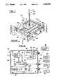
- FIG. 1is a perspective view, partially diagrammatic, of a antenna assembly incorporating the invention, a portion of a cover layer being partially cut away to expose components of the antenna assembly;
- FIG. 2is a plan view, partially diagrammatic, of the antenna assembly taken along the line 2--2 in FIG. 1, the view of FIG. 2 also showing external electronic equipment connected to the antenna assembly, the line 2--2 extending along a bottom surface of a ground plate of the antenna assembly;
- FIG. 3is a fragmentary portion of a sectional view taken along the line 3--3 in FIG. 1, FIG. 3 showing diagrammatically also a connection to electronic circuitry;
- FIG. 4is a stylized view of a motor vehicle with the antenna assembly of FIG. 1 mounted to an exterior surface of the vehicle;
- FIG. 5shows deployment of the antenna assembly of FIG. 1, in stylized fashion, upon the surface of the earth
- FIG. 6shows an alternative form of construction of the antenna assembly wherein portions of a loop component of the antenna assembly jump over feeds for a patch radiator of the assembly;
- FIGS. 7, 8 and 9show simplified fragmentary perspective views of alternative embodiments of the antenna assembly providing respectively for a circular patch and loop radiators, orthogonally disposed dipole radiators encircled by a rectangular loop and a dipole spiral configuration of radiator;
- FIG. 10is a sectional view, similar to that of FIG. 3, for a further embodiment of the invention employing a stack of three patch radiators for multiple frequency band use, FIG. 10 also showing diagrammatically a coupling of the patch radiators to electronic circuitry;
- FIG. 11shows a radiation pattern for a patch radiator of an antenna assembly of FIG. 1;
- FIG. 12shows a radiation pattern for a rod radiator of a patch antenna assembly of FIG. 1;
- FIG. 13shows a radiation pattern for a loop radiator of an antenna assembly of FIG. 1;
- FIG. 14is a fragmentary view of an alternative embodiment of the antenna assembly of FIG. 1 wherein a rod radiator incorporates a coil section.
- FIGS. 1-3show an antenna assembly 20 comprising a telescoping rod shaped radiator 22, a planar radiator 24 in the shape of a patch disposed about a base of the rod radiator 22, and a loop radiator 26 encircling both the planar radiator 24 and the rod radiator 22.
- the rod radiator 22, the planar radiator 24, and the loop radiator 26are supported upon a metallic, electrically-conducting plate 28 which serves as a ground plane of the antenna assembly 20, and also forms the top of a metallic box 30 which serves as a base of the antenna assembly 20.
- the box 30encloses coupling circuitry 32 by which external electronic components are coupled to the planar radiator 24 and the loop radiator 26, and to the body of the vehicle 30 as extended ground plane.
- the planar radiator 24is supported by a dielectric layer 34 which rests upon the plate 28 and serves as a spacer for providing a desired spacing between the planar radiator 24 and the plate 28.
- the dielectric layer 34extends outward beyond the planar radiator 24 to support the loop radiator 26 and to serve as a spacer between the loop radiator 26 and the plate 28.
- This form of constructionis recognized as the microstrip form of construction and, accordingly, both the planar radiator 24 and the loop radiator 26 are microstrip radiating components.
- a protective cover layer of an electrically insulating materialmay be provided on top of the planar radiator 24, the radiator 26 and exposed portions of the top surface of the plate 28.
- the planar radiator 24 and the loop radiator 26are fabricated of electrically conductive material, preferably a metal such as copper or aluminum which can be deposited on the dielectric layer and configured with a desired shape by photolithography and well-known etching procedures.
- the box 30 including both the plate 28 and sidewalls 38 of the box 30are fabricated of a metal such as copper or aluminum.
- the dielectric layer 34may be fabricated of a ceramic, electrically-insulating material such as alumina.
- the rod radiator 22is fabricated of a plurality of elongated cylindrical elements of which two such elements 40 and 42 are shown by way of example, the element 42 telescoping within the element 40.
- the rod radiatormay be fabricated with a choke to vary its electrical length, in terms of the number of wavelengths or fractional wavelength of received radiation, to accommodate various frequencies.
- the rod radiator 22is surrounded by a dielectric, electrically-insulating cuff 44 which encircles the base of the rod radiator 22 for positioning the rod radiator 22 upon the plate 28.
- the cuff 44allows the rod radiator 22 to pass through the planar radiator 24, the dielectric layer 34, and the plate 28 while maintaining electrical insulation between the rod radiator 22 and the planar radiator 24 as well as between the rod radiator 22 and the plate 28.
- a telescope drive 46is mounted on a bottom side of the plate 28, and is connected by mechanical links 48 and 50, indicated diagrammatically in FIG. 2, to the elements 40 and 42, respectively, of the rod radiator 22 for elevating the radiator 22 to a desired height, and for retracting the radiator 22 via a telescoping of the radiator 22.
- Electric signals for activating the drive 46are provided by an external source (such as a radio, telephone and/or ignition circuit, not shown) by wires 52.
- the planar radiator 24is provided with two terminals 54 and 56 which extend, respectively from sides 58 and 60 of the planar radiator 24, the two sides 58 and 60 being perpendicular.
- the terminal 54is located at the center of the side 58, and the terminal 56 is located at the center of the side 60.
- This arrangement of the terminals 54 and 56allows for a space-quadrature energization of the planar radiator 24 to produce a circularly polarized electromagnetic wave upon introduction of a phase shift of 90 degrees between signals applied to the terminals 54 and 56.
- the radiator 24can receive circularly polarized radiation with orthogonal components of the radiation appearing at the terminals 54 and 56.
- the terminals 54 and 56connect with the coupling circuitry 32 by means of coaxial transmission lines 62 and 64, respectively.
- Each of the transmission lines 62 and 64comprises an outer electrically-conductive metallic shell 66 and an inner central conductor 68 which are spaced apart by a dielectric, electrically-insulating cylinder 70.
- the central conductor 68connects with the terminal 54.
- the central conductor 68connects with the terminal 56.
- the central conductor 68for each of the transmission lines 62 and 64, passes through an aperture 72 in the plate 28 to make connection with the respective one of the terminals 54 and 56, the apertures 72 having the same diameters as the inner diameter of the shells 66.
- the loop radiator 26is cut to form two loop terminals 74 and 76 which connect via electrically-conductive rod elements 78, or insulated plated through holes (not shown), to the coupling circuitry 32.
- the rod elements 78pass via an aperture 80 (FIG. 2) in the plate 28.
- the coupling circuitry 32includes a hybrid circuit 82 for receipt of signals of a global positioning satellite (GPS), the hybrid circuit 82 combining the signals received by the transmission lines 62 and 64 into a single signal which is outputted via a coaxial connector 84 to electrical circuitry operative with a GPS system 86, the connector 84 being mounted in a sidewall 38 of the box 30.
- the hybrid circuit 82provides for a phase shift of 90 degrees between components of the circularly polarized signals communicated via the transmission lines 62 and 64 from the planar radiator 24 so as to combine the two components into a single output signal which is applied to the GPS system 86.
- the hybrid circuit 82is constructed in a well-known fashion, and may be realized as a microstrip circuit.
- the hybrid circuit 82is positioned at a location of convenience, such as by being mounted to a bottom surface of the plate 28, as indicated in FIG. 2, or by being placed directly on the top surface (not shown) of the dielectric layer 34 and connected to the terminals 54 and 56 by microstrip feed lines (not shown).
- the coupling circuitry 32comprises a further hybrid circuit 88 connecting via the rod elements 78 to the loop radiator 26.
- the hybrid circuit 88includes a balun 90 for coupling signals via a coaxial connector 92 to circuitry of a keyless entry system 94.
- the coaxial connector 92is mounted in a sidewall 38 of the box 30.
- An electromagnetic signal received by the loop radiator 26induces a phase shift of 90 degrees between the terminals 72 and 76 of the loop radiator 26 and, accordingly, the hybrid circuit 88 introduces a further phase of 90 degrees between these two signals so as to combine the two signals at the balun 90 for outputting to the keyless entry system 94.
- the hybrid circuit 88is fabricated of well-known circuitry, and is positioned at a location of convenience, such as by a mounting on the bottom surface of the plate 28, as is indicated in FIG. 2. It is to be understood that, with respect to both of the hybrid circuits 82 ad 88, the presentation of the circuits in FIG. 2 is diagrammatic and has been simplified by omitting well-known components such as terminating resistors for unused ports of the hybrid circuits.
- the coupling circuit 32also provides for connection of the element 42 of the rod radiator 22 via a coaxial connector 96 (FIG. 2) and a diplexer 98 for communication of signals to a telephone 100 and a radio 102.
- the center conductor of the connector 96is connected to the antenna elements 40 and 42.
- the diplexer 98is operative to separate signals in different frequency bands, thereby to apply telephone signals to the telephone 100 and radio signals to the radio 102.
- the diplexer 98operates in reciprocal fashion so as to communicate outgoing telephony signals from the telephone 100 to the rod radiator 22 for transmission therefrom.
- the ground plane of the plate 28cooperates with the rod radiator 22 in developing its monopole radiation pattern, the ground plane being connected via the box 30 to the outer conductor of the connector 96 by virtue of a mounting of the connector 96 to a sidewall 38 of the box 30.
- the antenna assembly 20is portable, as is shown in FIGS. 4 and 5.
- the antenna assembly 20is mounted in a depression in the fender of an automobile 104.
- the circuits of the keyless entry system 94, the GPS system 86, the telephone 100 and the radio 102are carried within the vehicle 104 and connected to the antenna assembly 20 as disclosed in FIG. 2.
- the automobile 104is understood to be fabricated of metal, particularly the outer surface thereof being formed as a metallic surface.
- the metallic surface of the automobile 104serves as a continuation of the ground plane of the plate 28 of the antenna assembly 20.
- the antenna assembly 20is mounted directly on the earth's surface, on the ground 106 which, by virtue of its electrical conductivity, serves as an extension of the ground plane provided by the plate 28 of the antenna assembly 20.
- the GPS system 86(not shown in FIG. 5) may be connected to the antenna assembly 20 so as to allow a hiker to determine his location in the forest.
- the telephone 100may be connected to the antenna system 20 to enable the hiker to communicate with people at distant locations.
- the antenna assembly 20 with its associated circuitrywould be operated by battery electric power (not shown).
- FIG. 6shows a fragmentary view of a antenna assembly 20A which is an alternative embodiment to the antenna assembly 20 of FIG. 1.
- the planar radiator 24is provided with microstrip feeds 108 connected to the terminals 54 and 56 for coupling signals between the planar patch radiator 24 and a hybrid circuit (not shown) such as the hybrid circuit 82 (FIG. 2), the hybrid circuit being positioned at a location of convenience either on top of the dielectric layer 34, or below the plate 28.
- the antenna assembly 20Aincludes a loop radiator 26A provided with wire sections 110 which jump over the feeds 108.
- the loop radiator 26Ais similar in both shape and function to that of the loop radiator 26 of FIG. 1.
- FIG. 7shows a fragmentary view of an antenna assembly 20B which is an alternative embodiment to the assembly of FIG. 1.
- the assembly 20Bincludes the planar radiator 24A configured as a circular patch and having the terminals 54 and 56, previously described, for coupling of signals from the planar radiator 24A.
- the planar radiator 24Ais encircled by a loop radiator 26B of circular configuration, in contrast to the square configuration of the loop radiator of FIG. 1.
- the planar radiator 24 and a loop radiator 26Bare supported by the dielectric layer 34 which, in turn, rests upon the plate 28 in the same manner as has been described above with reference to the antenna assembly of FIG. 1.
- Included in the assembly 20B of FIG. 7is the rod radiator 22 which functions in the same manner as described above with reference to FIG. 1.
- circular polarizationis produced and, with respect to the loop radiator 26B, the radiation pattern is essentially the same as that produced by the loop radiator 26 of FIG. 1.
- FIG. 8shows an antenna assembly 20C which is an alternative embodiment to the assembly of FIG. 1.
- the antenna assembly 20Ccomprises a planar radiator 24B comprising an array of four longitudinal radiating elements 112 forming two orthogonally positioned pairs of dipole radiators enclosed by the loop radiator 26.
- the radiating elements 112 and the loop radiator 26are supported by the dielectric layer 34 which, in turn, rests upon the plate 28.
- the rod radiator 22is located along a central axis of the antenna assembly 20C.
- the radiating elements 112 in each pairare colinear.
- the antenna assembly 20Cfurther comprises two hybrid circuits 114, indicated in phantom view, which function in a manner similar to that of the hybrid circuit 82 (FIG.
- the hybrid circuits 114are secured to the bottom surface of the plate 28 in the same fashion as has been described above for the hybrid circuit 82 in FIG. 2.
- the hybrid circuits 114serve the function of combining the signals of the paired radiating elements 112, and for introducing a phase shift of 180 degrees to accomplish the combining of the two signals.
- Output signals of the two hybrid circuits 114are, in turn, combined by a third hybrid circuit 118 which introduces a ninety degree phase shift between signals of the two hybrid circuits 114 to receive circularly polarized signals.
- a third hybrid circuit 118which introduces a ninety degree phase shift between signals of the two hybrid circuits 114 to receive circularly polarized signals.
- FIG. 9shows an antenna assembly 20D which is an alternative embodiment of the assembly of FIG. 1.
- the assembly 20Dincludes a planar radiator 24C comprising two spiral arms 120 spaced apart from and positioned symmetrically about the rod radiator 22.
- the spiral arms 120are surrounded by the loop radiator 26.
- the spiral arms 120 and the loop radiator 26are disposed upon the dielectric layer 34.
- Inboard ends of the spiral arms 120, facing the rod radiator 22,are connected by conductors 122, shown in phantom view, to a hybrid circuit 124.
- the conductors 122are oriented parallel to the rod radiator 22, and pass through the dielectric layer 34 and the plate 28 (not shown in FIG. 9) in the same fashion as disclosed for the conductors 68 of FIG. 1.
- the hybrid circuit 124is positioned at a location of convenience, such as by being mounted to the bottom surface of the plate 28.
- the hybrid circuit 124is operative to combine electromagnetic signals received by each of the arms 120 to provide a single output signal, as does the hybrid circuit 82 of FIG. 2.
- the hybrid circuit 124introduces a phase shift of 180 degrees between the arms 120 so as to accomplish the combining of the signals received by the two arms 120.
- an operating charaoteristic of a pair of spiral radiating elements, such as the two arms 120is the capacity to receive circularly polarized radiation, and the capacity to generate circularly polarized radiation upon a transmitting of an electromagnetic signal.
- the antenna assembly 20D of FIG. 9is capable of operating with the same radiation patterns and polarization as does the assembly 20 of FIG. 1.
- FIG. 10shows an antenna assembly 20E which is a further embodiment of the assembly of FIG. 1.
- the assembly 20E of FIG. 10differs from that of FIG. 1 in that the assembly 20E comprises a stack of three patch radiators 126, 128, and 130 which are stacked one upon the other instead of the single planar radiator 24 of FIG. 1.
- the assembly 20E of FIG. 10includes the loop radiator 26 and the rod radiator 22 which are constructed and function in the same fashion as has been described with reference to the assembly 20 of FIG. 1.
- the assembly 20E of FIG. 10also includes the cover layer 36, the cover layer 36 being partially cutaway to facilitate a showing of the components of the assembly 20E.
- the stack of the patch radiators 126, 128, and 130are configured as a pyramid 132 with the largest of the patch radiators 126 being at the bottom of the pyramid 132. The smallest of the patch radiators 130 is at the top of the pyramid 132, the remaining patch radiator 128 being of intermediate size and being disposed between the radiators 126 and 130.
- Each of the radiators 126, 128 and 130has a planar form, and is disposed parallel to the plate 28.
- the dielectric layer 34serves as a spacer between the bottom radiator 126 and the plate 28.
- a second dielectric layer 134serves as a spacer between the radiators 126 and 128.
- a third dielectric layer 136serves as a spacer between the radiators 128 and 130.
- Three hybrid circuits 13S, 140, and 142connect the patch radiators of the pyramid 132 to the GPS system 86.
- the stack of path radiators of FIG. 10provides for a greater bandwidth than the single planar radiator 24 of FIG. 1.
- the spiral arm configuration of FIG. 9also provides for a greater bandwidth than does the single planar patch radiator 24 of FIG. 1.
- the hybrid circuit 138connects via a coaxial. transmission line 144 to the bottom and largest patch radiator 126 for reception of electromagnetic signals at a lower frequency band F1.
- the hybrid circuit 140connects via a coaxial transmission line 146 to the middle patch radiator 128 for reception of electromagnetic signals at a middle frequency band F2.
- the hybrid circuit 142connects the top and smallest patch radiator 130 via a coaxial transmission line 148 for reception of electromagnetic signals at a higher frequency band F3.
- the three coaxial transmission lines 144, 146, and 148are constructed in the same general fashion as has been disclosed for the transmission lines 62 and 64 of FIG. 3.
- all of the transmission lines 144, 146, and 148comprises an outer shell 150, a central conductor 152, and a dielectric cylindrical spacer 154 which centers the conductor 152 within the shell 150 and insulates the conductor 152 from the shell 150.
- Each of the shellsconnects with the plate 28.
- the central conductors 152extend from the patch radiators 126, 128, and 130, respectively, to the hybrid circuits 138, 140, and 142, respectively.
- the shell 150extends up to the second dielectric layer 134, and is insulated from the radiator 126 by virtue of an aperture 156 in the radiator 126.
- the shell 150extends up to the third dielectric layer 132, and is insulated from the radiators 126 and 128 by virtue of apertures 158 and 160 respectively, within the radiators 126 and 128.
- the planar patch radiator 24has two terminals 54 and 56 which connect with two input terminals of the hybrid circuit 82 for reception of an electromagnetic signal.
- each of the patch radiators 126, 128, and 130are provided with two terminals for connection with the hybrid circuits 138, 140, and 142, respectively.
- FIG. 10only one terminal of respective ones of the patch radiators 126, 128, and 130 are shown connected via their respective transmission lines 144, 146, and 148 to their respective hybrid circuits 138, 140, and 142.
- a further set of three transmission linesconnects the second terminal (not shown) in each of the patch radiators 126, 128, and 130 to the remaining terminals 162 in each of the hybrid circuits 138, 140, and 142.
- a fourth terminal in each of the hybrid circuits 138, 140, and 142is shown terminated by a resistor 164.
- each of the hybrid couplers 138, 140, and 142is operative, during reception of circularly polarized electromagnetic signals, to combine the two orthogonal components of a received electromagnetic signal into a single output signal, respectively, for the patch radiators 126, 128, and 130.
- the patch radiators of the pyramid 132are operative to receive circularly polarized signals for operation of the GPS system 86.
- the loop radiator 26 and the rod radiator 22operate as has been described above with reference to FIGS. 1-3. Therefore, the antenna assembly 20E of FIG. 10 is operative with radiation patterns and polarizations in a manner similar to that described above with reference to the antenna assembly 20 of FIGS. 1-3.
- the patch radiators 126, 128, and 130may have a square shape, or a circular shape, or may be elongated in one direction such as in the case of a rectangular or elliptical shape should it be desired to alter the radiation pattern in one direction from that of the perpendicular direction.
- FIGS. 11, 12 and 13show radiation patterns for the three components of the antenna assembly 20 of FIG. 1, these figures being applicable also to the alternative embodiments of the antenna assembly disclosed in FIGS. 6-10.
- An XYZ coordinate axes systemis shown at 166 in FIG. 9, these coordinate axes being applicable also to the other embodiments of the antenna system.
- FIGS. 11, 12, and 13there is a graph presenting the intensity of the radiation patterns as a function of the coordinate axes X, Y, and Z. The intensity is represented by the length of a radius vector R in each graph.
- FIG. 11shows the radiation pattern provided by the planar patch radiator 24 of FIG. 1, and the corresponding embodiments thereof in FIGS. 6-10 for operation of the GPS system 86.
- FIG. 12shows the radiation pattern produced by the rod radiator 22 for operation of the telephone and the radio.
- FIG. 13shows the radiation pattern of the loop radiator for operation of the keyless entry system.
- FIG. 14shows an alternative embodiment of the antenna assembly of FIG. 1 wherein, instead of the rod radiator 22, there is provided a rod radiator 22A which incorporates a choke or coil section 168.
- the coil section 168loads the rod radiator 22A electrically so as to allow a shortening of its physical length, and also enhances reception of an electromagnetic signal in the event that the rod radiator 22A is inclined at an angle to the vertical. While the rod radiator 22A has been described with reference to the construction of the antenna assembly 20 of FIG. 1, it is to be understood that the rod radiator 22A may be incorporated into other ones of the antenna assembly of FIGS. 6-10.
- the rod radiatorhas an overall length which is greater than a cross-sectional dimension of the loop radiator, but is less than or equal to approximately one-half wavelength of the electromagnetic signal for the cellular telephony, and a much smaller fraction of a wavelength of the radio frequencies of both AM and FM reception.
- the size and the length of an antennaare important design parameters since an antenna is designed to radiate at a given desired mode for which a specific size and dimension is selected. Therefor, this embodiment could have various sizes to accomplish the same end result.
- a diameter of the loopis in the range of 4-6 percent of a wavelength of the electromagnetic signal.
- the planar radiatorwhether in the shape of the patch radiator of FIGS. 1-3, or the alternative embodiments of FIGS. 6-9, has a length on a side of approximately one-half wavelength of the electromagnetic signal for the global positioning satellite.
- each of the patch radiators of the pyramid 132has a length on a side of approximately one-half wavelength for the specific frequency band of the electromagnetic signal being received for the ground positioning system.
Landscapes
- Engineering & Computer Science (AREA)
- Remote Sensing (AREA)
- Waveguide Aerials (AREA)
- Variable-Direction Aerials And Aerial Arrays (AREA)
- Details Of Aerials (AREA)
- Mobile Radio Communication Systems (AREA)
Abstract
Description
This invention relates to portable antennas such as a vehicular antenna and, more particularly, to a unitary antenna structure having separate portions configured for reception of signals in different frequency bands.
Vehicular antenna systems, such as those mounted on automotive vehicles including cars and trucks, may be employed to provide a radio link for various electronic systems providing a number of functions, such as the keyless entry to the vehicle for remotely locking and unlocking the vehicle as well as turning lights and possibly the engine on and off. Additional functions include alarm activation and deactivation, cellular telephony, and radio including both AM and FM radio. Yet another function which may be employed is reception of signals received from a global positioning satellite (GPS) for navigating an automobile and for trip planning.
All of these functions are implemented with the aid of some type of a radio link requiring a transmitter and/or a receiver installed within the vehicle. The radio link for the various functions is accomplished by use of separate frequency bands designated for the individual functions. The frequency bands for these functions are as follows. The global positioning satellite operates in a frequency band of 1.2-1.6 GHz (gigahertz) with a nominal wavelength of 8.5 inches, the transmission of the GPS signal being in the nature of a spread spectrum modulation. The cellular telephony operates at a frequency of approximately 860 MHz (megahertz) and has a nominal wavelength of 14 inches. In the future, there may be microwave operation at L-Band and S-Band for satellite based cellular telephone. The AM radio operates in a frequency band 540-1600 KHz (kilohertz) and has a nominal wavelength of 1100 inches. The FM radio operates in a frequency band of 88-108 MHz, and has a nominal wavelength of 120 inches. The keyless vehicle entry operates at a nominal frequency of 315 MHz and has a nominal wavelength of 37.5 inches. It is anticipated that other functions facilitating the use and safety of motor vehicles will also become available, and that such functions will be allocated a specific band of the electromagnetic spectrum for communication with the vehicle. Presently, separate antennas are provided for accomplishing some of these functions. Some functions, such as the AM radio and the FM radio may be combined to operate with a single telescoping pole, or mast, operative as a monopole antenna.
A problem arises in that, heretofore, a vehicle, such as an automobile, must carry a variety of antennas to provide the benefits of the aforementioned functions. This is inconvenient from a point of view of manufacture and installation, as well as aesthetic appearance, and maintenance or repair of breakage or vandalism.
The aforementioned problem is overcome and other advantages are provided by an antenna system of the invention which is constructed as a unitary antenna assembly having separate portions, or components, which are operative in respective ones of the foregoing frequency bands designated for providing the functions of keyless entry, GPS, AM-FM radio, and cellular telephony. It is noted that the foregoing set of designated frequency bands is based on the present construction of such vehicular systems, and that other frequency bands may be employed for portable systems with their antennas, and various vehicular functions in the future.
In accordance with the invention, the unitary antenna structure includes a telescoping pole, or rod, operative as a monopole radiator, for reception of AM - FM radio signals, and for reception of cellular telephony. A microstrip patch antenna is provided for the GPS at a base of the telescoping pole. The pole is positioned directly in a metallic surface, of the vehicle, the metallic surface serving as a ground plane for radiation patterns produced by the components of the unitary antenna structure. Also included within the unitary antenna structure is a loop antenna which encircles the patch antenna, and is employed for the keyless-entry function. The pole antenna has a length less than approximately one-half wavelength of the FM signal. The patch antenna for the GPS has a size measuring approximately four inches, this being equal approximately to half wavelength of the GPS signal, the patch antenna being designed to radiate at a desired resonant mode. The loop antenna has a circumference only slightly larger than that of the microstrip patch antenna and, accordingly, has a cross-sectional dimension significantly smaller than one-quarter wavelength of the keyless-entry signal. The loop antenna is designed to radiate at a desired resonant mode for its geometry.
Each portion of the unitary antenna structure provides a desired shape of radiation pattern. The GPS microstrip patch antenna is designed to provide a generally hemispherical form of radiation pattern. The radiation pattern of telescoping pole is omnidirectional in a horizontal plane perpendicular to the pole. The loop antenna provides a radiation pattern having the form of a torus distributed symmetrically about an axis of the group antenna. The foregoing radiation patterns are understood to be measured at the far field, a distance of many wavelengths, from the antenna structure. However, since the components of the antenna structure may be on the order of a wavelength of some of the radiations, it is apparent that any electromagnetic interaction among components of the antenna system occur in the near field of various radiation patterns associated with each of the antenna components. Because of the near field coupling, and/or interaction, among the relatively small-closely-spaced-antenna components, inductance and capacitance between the various antenna components constitute factors determining the mutual impedance and loading of each antenna component upon an external circuit which either drives a component of the antenna or receives signals from a component of the antenna. In accordance with a feature of the invention, the configuration and the arrangement of the antenna components permit the antenna components to receive their designated signals, essentially without significant interference from other ones of the signals, so that all of the foregoing functions can be performed adequately.
The aforementioned aspects and other features of the invention are explained in the following description, taken in connection with the accompanying drawing wherein:
FIG. 1 is a perspective view, partially diagrammatic, of a antenna assembly incorporating the invention, a portion of a cover layer being partially cut away to expose components of the antenna assembly;
FIG. 2 is a plan view, partially diagrammatic, of the antenna assembly taken along theline 2--2 in FIG. 1, the view of FIG. 2 also showing external electronic equipment connected to the antenna assembly, theline 2--2 extending along a bottom surface of a ground plate of the antenna assembly;
FIG. 3 is a fragmentary portion of a sectional view taken along theline 3--3 in FIG. 1, FIG. 3 showing diagrammatically also a connection to electronic circuitry;
FIG. 4 is a stylized view of a motor vehicle with the antenna assembly of FIG. 1 mounted to an exterior surface of the vehicle;
FIG. 5 shows deployment of the antenna assembly of FIG. 1, in stylized fashion, upon the surface of the earth;
FIG. 6 shows an alternative form of construction of the antenna assembly wherein portions of a loop component of the antenna assembly jump over feeds for a patch radiator of the assembly;
FIGS. 7, 8 and 9 show simplified fragmentary perspective views of alternative embodiments of the antenna assembly providing respectively for a circular patch and loop radiators, orthogonally disposed dipole radiators encircled by a rectangular loop and a dipole spiral configuration of radiator;
FIG. 10 is a sectional view, similar to that of FIG. 3, for a further embodiment of the invention employing a stack of three patch radiators for multiple frequency band use, FIG. 10 also showing diagrammatically a coupling of the patch radiators to electronic circuitry;
FIG. 11 shows a radiation pattern for a patch radiator of an antenna assembly of FIG. 1;
FIG. 12 shows a radiation pattern for a rod radiator of a patch antenna assembly of FIG. 1;
FIG. 13 shows a radiation pattern for a loop radiator of an antenna assembly of FIG. 1; and
FIG. 14 is a fragmentary view of an alternative embodiment of the antenna assembly of FIG. 1 wherein a rod radiator incorporates a coil section.
FIGS. 1-3 show anantenna assembly 20 comprising a telescoping rod shapedradiator 22, aplanar radiator 24 in the shape of a patch disposed about a base of therod radiator 22, and aloop radiator 26 encircling both theplanar radiator 24 and therod radiator 22. Therod radiator 22, theplanar radiator 24, and theloop radiator 26 are supported upon a metallic, electrically-conductingplate 28 which serves as a ground plane of theantenna assembly 20, and also forms the top of ametallic box 30 which serves as a base of theantenna assembly 20. Thebox 30 enclosescoupling circuitry 32 by which external electronic components are coupled to theplanar radiator 24 and theloop radiator 26, and to the body of thevehicle 30 as extended ground plane.
Theplanar radiator 24 is supported by adielectric layer 34 which rests upon theplate 28 and serves as a spacer for providing a desired spacing between theplanar radiator 24 and theplate 28. Thedielectric layer 34 extends outward beyond theplanar radiator 24 to support theloop radiator 26 and to serve as a spacer between theloop radiator 26 and theplate 28. This form of construction is recognized as the microstrip form of construction and, accordingly, both theplanar radiator 24 and theloop radiator 26 are microstrip radiating components. If desired, a protective cover layer of an electrically insulating material may be provided on top of theplanar radiator 24, theradiator 26 and exposed portions of the top surface of theplate 28. Theplanar radiator 24 and theloop radiator 26 are fabricated of electrically conductive material, preferably a metal such as copper or aluminum which can be deposited on the dielectric layer and configured with a desired shape by photolithography and well-known etching procedures. Similarly, thebox 30 including both theplate 28 andsidewalls 38 of thebox 30 are fabricated of a metal such as copper or aluminum. Thedielectric layer 34 may be fabricated of a ceramic, electrically-insulating material such as alumina.
Therod radiator 22 is fabricated of a plurality of elongated cylindrical elements of which twosuch elements element 42 telescoping within theelement 40. By way of example in the construction of an alternative embodiment of the rod radiator, as will be described with reference to FIG. 14, the rod radiator may be fabricated with a choke to vary its electrical length, in terms of the number of wavelengths or fractional wavelength of received radiation, to accommodate various frequencies. Therod radiator 22 is surrounded by a dielectric, electrically-insulatingcuff 44 which encircles the base of therod radiator 22 for positioning therod radiator 22 upon theplate 28. Thecuff 44 allows therod radiator 22 to pass through theplanar radiator 24, thedielectric layer 34, and theplate 28 while maintaining electrical insulation between therod radiator 22 and theplanar radiator 24 as well as between therod radiator 22 and theplate 28. Atelescope drive 46 is mounted on a bottom side of theplate 28, and is connected bymechanical links elements rod radiator 22 for elevating theradiator 22 to a desired height, and for retracting theradiator 22 via a telescoping of theradiator 22. Electric signals for activating thedrive 46 are provided by an external source (such as a radio, telephone and/or ignition circuit, not shown) bywires 52.
Theplanar radiator 24 is provided with twoterminals sides planar radiator 24, the twosides side 58, and the terminal 56 is located at the center of theside 60. This arrangement of theterminals planar radiator 24 to produce a circularly polarized electromagnetic wave upon introduction of a phase shift of 90 degrees between signals applied to theterminals planar radiator 24, theradiator 24 can receive circularly polarized radiation with orthogonal components of the radiation appearing at theterminals terminals coupling circuitry 32 by means ofcoaxial transmission lines transmission lines metallic shell 66 and an innercentral conductor 68 which are spaced apart by a dielectric, electrically-insulatingcylinder 70. In thetransmission line 62, thecentral conductor 68 connects with the terminal 54. In thetransmission line 64, thecentral conductor 68 connects with the terminal 56. Thecentral conductor 68, for each of thetransmission lines aperture 72 in theplate 28 to make connection with the respective one of theterminals apertures 72 having the same diameters as the inner diameter of theshells 66. In similar fashion, theloop radiator 26 is cut to form twoloop terminals conductive rod elements 78, or insulated plated through holes (not shown), to thecoupling circuitry 32. Therod elements 78 pass via an aperture 80 (FIG. 2) in theplate 28.
Thecoupling circuitry 32 includes ahybrid circuit 82 for receipt of signals of a global positioning satellite (GPS), thehybrid circuit 82 combining the signals received by thetransmission lines coaxial connector 84 to electrical circuitry operative with aGPS system 86, theconnector 84 being mounted in asidewall 38 of thebox 30. Thehybrid circuit 82 provides for a phase shift of 90 degrees between components of the circularly polarized signals communicated via thetransmission lines planar radiator 24 so as to combine the two components into a single output signal which is applied to theGPS system 86. Thehybrid circuit 82 is constructed in a well-known fashion, and may be realized as a microstrip circuit. Thehybrid circuit 82 is positioned at a location of convenience, such as by being mounted to a bottom surface of theplate 28, as indicated in FIG. 2, or by being placed directly on the top surface (not shown) of thedielectric layer 34 and connected to theterminals
Thecoupling circuitry 32 comprises afurther hybrid circuit 88 connecting via therod elements 78 to theloop radiator 26. Thehybrid circuit 88 includes abalun 90 for coupling signals via acoaxial connector 92 to circuitry of akeyless entry system 94. Thecoaxial connector 92 is mounted in asidewall 38 of thebox 30. An electromagnetic signal received by theloop radiator 26 induces a phase shift of 90 degrees between theterminals loop radiator 26 and, accordingly, thehybrid circuit 88 introduces a further phase of 90 degrees between these two signals so as to combine the two signals at thebalun 90 for outputting to thekeyless entry system 94. Thehybrid circuit 88 is fabricated of well-known circuitry, and is positioned at a location of convenience, such as by a mounting on the bottom surface of theplate 28, as is indicated in FIG. 2. It is to be understood that, with respect to both of thehybrid circuits 82ad 88, the presentation of the circuits in FIG. 2 is diagrammatic and has been simplified by omitting well-known components such as terminating resistors for unused ports of the hybrid circuits.
Thecoupling circuit 32 also provides for connection of theelement 42 of therod radiator 22 via a coaxial connector 96 (FIG. 2) and adiplexer 98 for communication of signals to atelephone 100 and aradio 102. The center conductor of theconnector 96 is connected to theantenna elements diplexer 98 is operative to separate signals in different frequency bands, thereby to apply telephone signals to thetelephone 100 and radio signals to theradio 102. Thediplexer 98 operates in reciprocal fashion so as to communicate outgoing telephony signals from thetelephone 100 to therod radiator 22 for transmission therefrom. The ground plane of theplate 28 cooperates with therod radiator 22 in developing its monopole radiation pattern, the ground plane being connected via thebox 30 to the outer conductor of theconnector 96 by virtue of a mounting of theconnector 96 to asidewall 38 of thebox 30.
Theantenna assembly 20 is portable, as is shown in FIGS. 4 and 5. In FIG. 4, theantenna assembly 20 is mounted in a depression in the fender of anautomobile 104. The circuits of thekeyless entry system 94, theGPS system 86, thetelephone 100 and the radio 102 (shown in FIG. 2 but not in FIG. 4) are carried within thevehicle 104 and connected to theantenna assembly 20 as disclosed in FIG. 2. Theautomobile 104 is understood to be fabricated of metal, particularly the outer surface thereof being formed as a metallic surface. The metallic surface of theautomobile 104 serves as a continuation of the ground plane of theplate 28 of theantenna assembly 20. In FIG. 5, theantenna assembly 20 is mounted directly on the earth's surface, on theground 106 which, by virtue of its electrical conductivity, serves as an extension of the ground plane provided by theplate 28 of theantenna assembly 20. By way of example in the use of theantenna assembly 20 of FIG. 5, the GPS system 86 (not shown in FIG. 5) may be connected to theantenna assembly 20 so as to allow a hiker to determine his location in the forest. Also, if desired, thetelephone 100 may be connected to theantenna system 20 to enable the hiker to communicate with people at distant locations. In the situation of FIG. 5, theantenna assembly 20 with its associated circuitry would be operated by battery electric power (not shown).
FIG. 6 shows a fragmentary view of aantenna assembly 20A which is an alternative embodiment to theantenna assembly 20 of FIG. 1. In FIG. 6, theplanar radiator 24 is provided with microstrip feeds 108 connected to theterminals planar patch radiator 24 and a hybrid circuit (not shown) such as the hybrid circuit 82 (FIG. 2), the hybrid circuit being positioned at a location of convenience either on top of thedielectric layer 34, or below theplate 28. Theantenna assembly 20A includes aloop radiator 26A provided withwire sections 110 which jump over thefeeds 108. In other respects, theloop radiator 26A is similar in both shape and function to that of theloop radiator 26 of FIG. 1.
FIG. 7 shows a fragmentary view of anantenna assembly 20B which is an alternative embodiment to the assembly of FIG. 1. In FIG. 7, theassembly 20B includes theplanar radiator 24A configured as a circular patch and having theterminals planar radiator 24A. Theplanar radiator 24A is encircled by aloop radiator 26B of circular configuration, in contrast to the square configuration of the loop radiator of FIG. 1. Theplanar radiator 24 and aloop radiator 26B are supported by thedielectric layer 34 which, in turn, rests upon theplate 28 in the same manner as has been described above with reference to the antenna assembly of FIG. 1. Included in theassembly 20B of FIG. 7 is therod radiator 22 which functions in the same manner as described above with reference to FIG. 1. In the operation of theplanar radiator 24A, circular polarization is produced and, with respect to theloop radiator 26B, the radiation pattern is essentially the same as that produced by theloop radiator 26 of FIG. 1.
FIG. 8 shows anantenna assembly 20C which is an alternative embodiment to the assembly of FIG. 1. In FIG. 8, theantenna assembly 20C comprises aplanar radiator 24B comprising an array of fourlongitudinal radiating elements 112 forming two orthogonally positioned pairs of dipole radiators enclosed by theloop radiator 26. The radiatingelements 112 and theloop radiator 26 are supported by thedielectric layer 34 which, in turn, rests upon theplate 28. Therod radiator 22 is located along a central axis of theantenna assembly 20C. The radiatingelements 112 in each pair are colinear. Theantenna assembly 20C further comprises twohybrid circuits 114, indicated in phantom view, which function in a manner similar to that of the hybrid circuit 82 (FIG. 2) for providing output signals in response to illumination of the dipoles of the pairedelements 112 during reception of an electromagnetic signal. The inboard ends of the radiatingelements 112, facing therod radiator 22, connect viaconductors 116 to terminals of thehybrid circuits 114. Theconductors 116 are parallel to therod radiator 22. Theconductors 116 pass through thedielectric layer 34 and theplate 28 in the same manner as do theconductors 68 of FIG. 2. Thehybrid circuits 114 are secured to the bottom surface of theplate 28 in the same fashion as has been described above for thehybrid circuit 82 in FIG. 2. Thehybrid circuits 114 serve the function of combining the signals of the paired radiatingelements 112, and for introducing a phase shift of 180 degrees to accomplish the combining of the two signals. Output signals of the twohybrid circuits 114 are, in turn, combined by a thirdhybrid circuit 118 which introduces a ninety degree phase shift between signals of the twohybrid circuits 114 to receive circularly polarized signals. Thus, the operation of theantenna assembly 20C of FIG. 8 is in accord with that of the antenna assembly 14 of FIG. 1.
FIG. 9 shows anantenna assembly 20D which is an alternative embodiment of the assembly of FIG. 1. In FIG. 9, theassembly 20D includes a planar radiator 24C comprising twospiral arms 120 spaced apart from and positioned symmetrically about therod radiator 22. Thespiral arms 120 are surrounded by theloop radiator 26. Thespiral arms 120 and theloop radiator 26 are disposed upon thedielectric layer 34. Inboard ends of thespiral arms 120, facing therod radiator 22, are connected byconductors 122, shown in phantom view, to ahybrid circuit 124. Theconductors 122 are oriented parallel to therod radiator 22, and pass through thedielectric layer 34 and the plate 28 (not shown in FIG. 9) in the same fashion as disclosed for theconductors 68 of FIG. 1. Thehybrid circuit 124 is positioned at a location of convenience, such as by being mounted to the bottom surface of theplate 28. Thehybrid circuit 124 is operative to combine electromagnetic signals received by each of thearms 120 to provide a single output signal, as does thehybrid circuit 82 of FIG. 2. In addition, thehybrid circuit 124 introduces a phase shift of 180 degrees between thearms 120 so as to accomplish the combining of the signals received by the twoarms 120. As is well known, an operating charaoteristic of a pair of spiral radiating elements, such as the twoarms 120, is the capacity to receive circularly polarized radiation, and the capacity to generate circularly polarized radiation upon a transmitting of an electromagnetic signal. Thus, theantenna assembly 20D of FIG. 9 is capable of operating with the same radiation patterns and polarization as does theassembly 20 of FIG. 1.
FIG. 10 shows anantenna assembly 20E which is a further embodiment of the assembly of FIG. 1. Theassembly 20E of FIG. 10 differs from that of FIG. 1 in that theassembly 20E comprises a stack of threepatch radiators planar radiator 24 of FIG. 1. Theassembly 20E of FIG. 10 includes theloop radiator 26 and therod radiator 22 which are constructed and function in the same fashion as has been described with reference to theassembly 20 of FIG. 1. Theassembly 20E of FIG. 10 also includes thecover layer 36, thecover layer 36 being partially cutaway to facilitate a showing of the components of theassembly 20E. The stack of thepatch radiators pyramid 132 with the largest of thepatch radiators 126 being at the bottom of thepyramid 132. The smallest of thepatch radiators 130 is at the top of thepyramid 132, the remainingpatch radiator 128 being of intermediate size and being disposed between theradiators radiators plate 28.
Thedielectric layer 34 serves as a spacer between thebottom radiator 126 and theplate 28. Asecond dielectric layer 134 serves as a spacer between theradiators third dielectric layer 136 serves as a spacer between theradiators hybrid circuits pyramid 132 to theGPS system 86.
The stack of path radiators of FIG. 10 provides for a greater bandwidth than the singleplanar radiator 24 of FIG. 1. The spiral arm configuration of FIG. 9 also provides for a greater bandwidth than does the singleplanar patch radiator 24 of FIG. 1. In FIG. 10, thehybrid circuit 138 connects via a coaxial.transmission line 144 to the bottom andlargest patch radiator 126 for reception of electromagnetic signals at a lower frequency band F1. Thehybrid circuit 140 connects via acoaxial transmission line 146 to themiddle patch radiator 128 for reception of electromagnetic signals at a middle frequency band F2. Thehybrid circuit 142 connects the top andsmallest patch radiator 130 via acoaxial transmission line 148 for reception of electromagnetic signals at a higher frequency band F3.
The threecoaxial transmission lines transmission lines transmission lines outer shell 150, acentral conductor 152, and a dielectriccylindrical spacer 154 which centers theconductor 152 within theshell 150 and insulates theconductor 152 from theshell 150. Each of the shells connects with theplate 28. In thetransmission lines central conductors 152 extend from thepatch radiators hybrid circuits transmission line 146, theshell 150 extends up to thesecond dielectric layer 134, and is insulated from theradiator 126 by virtue of anaperture 156 in theradiator 126. In thetransmission line 148, theshell 150 extends up to the thirddielectric layer 132, and is insulated from theradiators apertures radiators
As has been disclosed in the embodiment of the antenna assembly of FIGS. 1-3, theplanar patch radiator 24 has twoterminals hybrid circuit 82 for reception of an electromagnetic signal. In similar fashion, in FIG. 10, each of thepatch radiators hybrid circuits antenna assembly 20E, in FIG. 10, only one terminal of respective ones of thepatch radiators respective transmission lines hybrid circuits patch radiators terminals 162 in each of thehybrid circuits hybrid circuits resistor 164.
In operation, each of thehybrid couplers patch radiators pyramid 132 are operative to receive circularly polarized signals for operation of theGPS system 86. Theloop radiator 26 and therod radiator 22 operate as has been described above with reference to FIGS. 1-3. Therefore, theantenna assembly 20E of FIG. 10 is operative with radiation patterns and polarizations in a manner similar to that described above with reference to theantenna assembly 20 of FIGS. 1-3. Thepatch radiators
FIGS. 11, 12 and 13 show radiation patterns for the three components of theantenna assembly 20 of FIG. 1, these figures being applicable also to the alternative embodiments of the antenna assembly disclosed in FIGS. 6-10. An XYZ coordinate axes system is shown at 166 in FIG. 9, these coordinate axes being applicable also to the other embodiments of the antenna system. In each of FIGS. 11, 12, and 13, there is a graph presenting the intensity of the radiation patterns as a function of the coordinate axes X, Y, and Z. The intensity is represented by the length of a radius vector R in each graph. FIG. 11 shows the radiation pattern provided by theplanar patch radiator 24 of FIG. 1, and the corresponding embodiments thereof in FIGS. 6-10 for operation of theGPS system 86. FIG. 12 shows the radiation pattern produced by therod radiator 22 for operation of the telephone and the radio. FIG. 13 shows the radiation pattern of the loop radiator for operation of the keyless entry system.
FIG. 14 shows an alternative embodiment of the antenna assembly of FIG. 1 wherein, instead of therod radiator 22, there is provided arod radiator 22A which incorporates a choke orcoil section 168. Thecoil section 168 loads therod radiator 22A electrically so as to allow a shortening of its physical length, and also enhances reception of an electromagnetic signal in the event that therod radiator 22A is inclined at an angle to the vertical. While therod radiator 22A has been described with reference to the construction of theantenna assembly 20 of FIG. 1, it is to be understood that therod radiator 22A may be incorporated into other ones of the antenna assembly of FIGS. 6-10.
With respect to the physical sizes of the radiators of theantenna assembly 20, and of the various embodiments thereof, the rod radiator has an overall length which is greater than a cross-sectional dimension of the loop radiator, but is less than or equal to approximately one-half wavelength of the electromagnetic signal for the cellular telephony, and a much smaller fraction of a wavelength of the radio frequencies of both AM and FM reception. The size and the length of an antenna are important design parameters since an antenna is designed to radiate at a given desired mode for which a specific size and dimension is selected. Therefor, this embodiment could have various sizes to accomplish the same end result. In the case of the loop radiator for reception of signals for the keyless entry system, a diameter of the loop is in the range of 4-6 percent of a wavelength of the electromagnetic signal. The planar radiator, whether in the shape of the patch radiator of FIGS. 1-3, or the alternative embodiments of FIGS. 6-9, has a length on a side of approximately one-half wavelength of the electromagnetic signal for the global positioning satellite. In the case of the antenna assembly of
FIG. 10, each of the patch radiators of thepyramid 132 has a length on a side of approximately one-half wavelength for the specific frequency band of the electromagnetic signal being received for the ground positioning system.
It is to be understood that the above described embodiments of the invention are illustrative only, and that modifications thereof may occur to those skilled in the art. Accordingly, this invention is not to be regarded as limited to the embodiments disclosed herein, but is to be limited only as defined by the appended claims.
Claims (18)
1. A multiple band antenna comprising:
an electrically conductive plate serving as a ground plane;
a first planar electrically conductive radiator disposed parallel to said ground plane, and a first dielectric layer interposed between said first planar radiator and said ground plane;
an elongated electrically conductive rod radiator extending through a central portion of said planar radiator and oriented normally to said planar radiator;
means for insulating said rod radiator from said planar radiator;
a loop radiator encircling said planar radiator and being electrically insulated from said planar radiator;
a second planar electrically conductive radiator disposed parallel to said first planar radiator and being located on a side of said first planar radiator opposite said ground plane;
a second dielectric layer interposed between said second planar radiator and said first planar radiator;
a first transmission line extending through said ground plane and said first dielectric layer to couple with said first planar radiator for coupling a first electromagnetic signal from said first planar radiator upon reception of electromagnetic radiation by said antenna;
a second transmission line extending through said ground plane and said first dielectric layer and said first planar radiator and said second dielectric layer to couple with said second planar radiator for coupling a second electromagnetic signal from said second planar radiator, said second planar radiator being smaller than said first planar radiator, and said second electromagnetic signal having a smaller wavelength than said first electromagnetic signal;
wherein a diameter of said first planar radiator and of said loop radiator is less than or equal approximately to one-half of a wavelength of radiation to be received respectively by said first planar radiator and said loop radiator; and
said rod radiator has an electrical length greater than a cross-sectional dimension of said loop radiator for reception of radiation having a longer wavelength than radiation for said first planar radiator and for said loop radiator.
2. An antenna according to claim 1 wherein said loop radiator is disposed in a plane parallel to said ground plane, and said first dielectric layer extends between said loop radiator and said ground plane.
3. An antenna according to claim 2 wherein said loop radiator has a configuration which is square, said loop radiator having a first terminal and a second terminal adjacent to said first terminal, said loop radiator extending from said first terminal around said first planar radiator to said second terminal.
4. An antenna according to claim 1 wherein said insulating means comprises a dielectric cylinder disposed about said rod radiator.
5. An antenna according to claim 4 wherein said ground plane has an aperture therein for receiving said dielectric cylinder for supporting said rod radiator upon said plate, said aperture allowing passage of said rod radiator through said plate for coupling signals received by said rod radiator.
6. An antenna according to claim 1 wherein said first planar radiator is configured for reception of circularly polarized radiation, said antenna including a third transmission line, said first and said third transmission lines being coupled to spaced-apart positions of said first planar radiator for coupling orthogonal components of an electromagnetic signal from said first planar radiator.
7. An antenna according to claim 6 wherein said first planar radiator has a configuration of a rectangular patch.
8. An antenna according to claim 6 wherein said first planar radiator is a patch radiator, said second planar radiator being a patch radiator encircling said rod radiator.
9. An antenna according to claim 6 wherein said loop radiator is disposed in a plane parallel to said plate, and said first dielectric layer extends between said loop radiator and said plate.
10. An antenna according to claim 9 wherein
said insulating means comprises a dielectric cylinder disposed about said rod radiator; and
said ground plane has an aperture therein for receiving said dielectric cylinder for supporting said rod radiator upon said plate, said aperture allowing passage of said rod radiator through said plate for coupling signals received by said rod radiator.
11. An antenna according to claim 10 further comprising a protective cover layer of electrically insulating material disposed upon said first and said second planar radiators and said loop radiator.
12. An antenna according to claim 11 further comprising means for telescoping said rod radiator.
13. An antenna according to claim 1 further comprising a third planar radiator smaller than said second planar radiator, and a third dielectric layer;
wherein said third planar radiator is disposed parallel to said second planar radiator and on a side thereof opposite said ground plane, and said third dielectric layer is disposed between said second planar radiator and said third planar radiator; and said antenna further comprises a third transmission line passing through said ground plane and said first dielectric layer and said first planar radiator and said second dielectric layer and said second planar radiator and said third dielectric layer to couple with said third planar radiator for coupling a third electromagnetic signal from said third planar radiator upon reception of electromagnetic radiation by said antenna, said third electromagnetic signal having a wavelength smaller than the wavelength of said second electromagnetic signal.
14. An antenna according to claim 2 wherein said loop radiator has a configuration which is round, said loop radiator having a first terminal and a second terminal adjacent to said first terminal, said loop radiator extending from said first terminal around said first planar radiator to said second terminal.
15. An antenna according to claim 6 wherein said first planar radiator has a configuration of a spiral patch.
16. An antenna according to claim 6 wherein said first planar radiator has a configuration of a crossed dipole patch.
17. A multiple band antenna comprising:
an electrically conductive plate serving as a ground plane;
a first planar electrically conductive radiator disposed parallel to said ground plane, and a first dielectric layer interposed between said first planar radiator and said ground plane;
an elongated electrically conductive rod radiator extending through a central portion of said planar radiator and oriented normally to said planar radiator;
means for insulating said rod radiator from said planar radiator;
a loop radiator encircling said planar radiator and being electrically insulated from said planar radiator;
a second planar electrically conductive radiator disposed parallel to said first planar radiator and being located on a side of said first planar radiator opposite said ground plane;
a second dielectric layer interposed between said second planar radiator and said first planar radiator, said second planar radiator being smaller than said first planar radiator, and said second electromagnetic signal having a smaller wavelength than said first electromagnetic signal;
wherein a diameter of said first planar radiator and of said loop radiator is less than or equal approximately to one-half of a wavelength of radiation to be received respectively by said first planar radiator and said loop radiator; and
said rod radiator has an electrical length greater than a cross-sectional dimension of said loop radiator for reception of radiation having a longer wavelength than radiation for said first planar radiator and for said loop radiator.
18. A multiple band antenna comprising:
an electrically conductive plate serving as a ground plane;
a first planar electrically conductive radiator disposed parallel to said ground plane;
an elongated electrically conductive rod radiator extending through a central portion of said planar radiator and oriented normally to said planar radiator;
means for insulating said rod radiator from said planar radiator;
a loop radiator encircling said planar radiator and being electrically insulated from said planar radiator;
a second planar electrically conductive radiator disposed parallel to said first planar radiator and being located on a side of said first planar radiator opposite said ground plane, said second planar radiator being spaced apart from said first planar radiator, said second planar radiator being smaller than said first planar radiator, and said second electromagnetic signal having a smaller wavelength than said first electromagnetic signal;
wherein a diameter of said first planar radiator and of said loop radiator is less than or equal approximately to one-half of a wavelength of radiation to be received respectively by said first planar radiator and said loop radiator; and
said rod radiator has an electrical length greater than a cross-sectional dimension of said loop radiator for reception of radiation having a longer wavelength than radiation for said first planar radiator and for said loop radiator.
Priority Applications (5)
| Application Number | Priority Date | Filing Date | Title |
|---|---|---|---|
| US07/954,274US5300936A (en) | 1992-09-30 | 1992-09-30 | Multiple band antenna |
| KR1019930007251AKR100279696B1 (en) | 1992-09-30 | 1993-04-28 | Multiband antenna |
| JP5104399AJP2553299B2 (en) | 1992-09-30 | 1993-04-30 | Antenna system |
| EP93307720AEP0590955B1 (en) | 1992-09-30 | 1993-09-29 | Multiple band antenna |
| DE69326984TDE69326984T2 (en) | 1992-09-30 | 1993-09-29 | Antenna for multiple frequency ranges |
Applications Claiming Priority (1)
| Application Number | Priority Date | Filing Date | Title |
|---|---|---|---|
| US07/954,274US5300936A (en) | 1992-09-30 | 1992-09-30 | Multiple band antenna |
Publications (1)
| Publication Number | Publication Date |
|---|---|
| US5300936Atrue US5300936A (en) | 1994-04-05 |
Family
ID=25495201
Family Applications (1)
| Application Number | Title | Priority Date | Filing Date |
|---|---|---|---|
| US07/954,274Expired - LifetimeUS5300936A (en) | 1992-09-30 | 1992-09-30 | Multiple band antenna |
Country Status (5)
| Country | Link |
|---|---|
| US (1) | US5300936A (en) |
| EP (1) | EP0590955B1 (en) |
| JP (1) | JP2553299B2 (en) |
| KR (1) | KR100279696B1 (en) |
| DE (1) | DE69326984T2 (en) |
Cited By (92)
| Publication number | Priority date | Publication date | Assignee | Title |
|---|---|---|---|---|
| US5461387A (en)* | 1994-06-10 | 1995-10-24 | Georgia Tech Research Corporation | Position and direction finding instrument |
| US5508710A (en)* | 1994-03-11 | 1996-04-16 | Wang-Tripp Corporation | Conformal multifunction shared-aperture antenna |
| US5541609A (en)* | 1995-03-08 | 1996-07-30 | Virginia Polytechnic Institute And State University | Reduced operator emission exposure antennas for safer hand-held radios and cellular telephones |
| US5604506A (en)* | 1994-12-13 | 1997-02-18 | Trimble Navigation Limited | Dual frequency vertical antenna |
| US5606334A (en)* | 1995-03-27 | 1997-02-25 | Amarillas; Sal G. | Integrated antenna for satellite and terrestrial broadcast reception |
| US5610620A (en)* | 1995-05-19 | 1997-03-11 | Comant Industries, Inc. | Combination antenna |
| US5640139A (en)* | 1995-09-14 | 1997-06-17 | Egeberg; Gerald W. | Wireless control of electronic door locking devices for trailers |
| US5654717A (en)* | 1995-08-03 | 1997-08-05 | Trimble Navigation, Ltd. | GPS/radio antenna combination |
| US5673053A (en)* | 1993-09-06 | 1997-09-30 | Allgon Ab | Antenna coupling device for coupling an antenna of a hand-portable telephone to a remotely located antenna |
| US5726893A (en)* | 1992-12-17 | 1998-03-10 | Stanford Telecommunications, Inc. | Cellular telephone with voice-in-data modem |
| US5751252A (en)* | 1995-06-21 | 1998-05-12 | Motorola, Inc. | Method and antenna for providing an omnidirectional pattern |
| US5752204A (en)* | 1996-04-01 | 1998-05-12 | Telefonaktiebolaget L M Ericsson (Publ) | Antenna assembly for radiotelephonic device |
| US5812097A (en)* | 1996-04-30 | 1998-09-22 | Qualcomm Incorporated | Dual band antenna |
| US5838282A (en)* | 1996-03-22 | 1998-11-17 | Ball Aerospace And Technologies Corp. | Multi-frequency antenna |
| US5945959A (en)* | 1996-09-12 | 1999-08-31 | Mitsubishi Materials Corporation | Surface mounting antenna having a dielectric base and a radiating conductor film |
| US5952971A (en)* | 1997-02-27 | 1999-09-14 | Ems Technologies Canada, Ltd. | Polarimetric dual band radiating element for synthetic aperture radar |
| US5999140A (en)* | 1997-10-17 | 1999-12-07 | Rangestar International Corporation | Directional antenna assembly |
| US6016128A (en)* | 1997-09-04 | 2000-01-18 | Harada Industry Co., Ltd. | GPS wave antenna apparatus |
| US6023245A (en)* | 1998-08-10 | 2000-02-08 | Andrew Corporation | Multi-band, multiple purpose antenna particularly useful for operation in cellular and global positioning system modes |
| US6087989A (en)* | 1997-03-31 | 2000-07-11 | Samsung Electronics Co., Ltd. | Cavity-backed microstrip dipole antenna array |
| US6104348A (en)* | 1997-07-23 | 2000-08-15 | Allgon Ab | Antenna device with improved channel isolation |
| US6151480A (en)* | 1997-06-27 | 2000-11-21 | Adc Telecommunications, Inc. | System and method for distributing RF signals over power lines within a substantially closed environment |
| US6160512A (en)* | 1997-10-20 | 2000-12-12 | Nec Corporation | Multi-mode antenna |
| US6239750B1 (en)* | 1998-08-28 | 2001-05-29 | Telefonaltiebolaget Lm Ericsson (Publ) | Antenna arrangement |
| US6249260B1 (en) | 1999-07-16 | 2001-06-19 | Comant Industries, Inc. | T-top antenna for omni-directional horizontally-polarized operation |
| US6281852B1 (en)* | 1995-03-27 | 2001-08-28 | Sal Amarillas | Integrated antenna for satellite and terrestrial broadcast reception |
| US6313801B1 (en)* | 2000-08-25 | 2001-11-06 | Telefonaktiebolaget Lm Ericsson | Antenna structures including orthogonally oriented antennas and related communications devices |
| DE10025992A1 (en)* | 2000-05-25 | 2002-01-03 | Siemens Ag | Antenna system e.g. for mobile telephone has respective electrically and magnetically active antennas spaced in near field |
| US6339403B1 (en)* | 1999-06-30 | 2002-01-15 | Siemens Automotive Corporation | Vehicle antenna system for multiple vehicle electronic components |
| US6433749B1 (en)* | 1998-06-17 | 2002-08-13 | Harada Inductries (Europe) Limited | Antenna assembly |
| US20020158808A1 (en)* | 2000-03-10 | 2002-10-31 | Jinichi Inoue | Cross dipole antenna and composite antenna |
| US20030071716A1 (en)* | 2001-10-12 | 2003-04-17 | Visteon Global Technologies, Inc. | Antenna system architecture with integrated systems |
| US20030189519A1 (en)* | 2000-07-10 | 2003-10-09 | Tomas Rutfors | Antenna device |
| US20030197651A1 (en)* | 2002-04-17 | 2003-10-23 | Alps Electric Co., Ltd. | Dual antenna capable of transmitting and receiving circularly polarized electromagnetic wave and linearly polarized electromagnetic wave |
| US20030210193A1 (en)* | 2002-05-13 | 2003-11-13 | Rossman Court Emerson | Low Profile Two-Antenna Assembly Having a Ring Antenna and a Concentrically-Located Monopole Antenna |
| US20040008143A1 (en)* | 2002-06-28 | 2004-01-15 | Seishin Mikami | Antenna apparatus and method for mounting antenna |
| US6765542B2 (en) | 2002-09-23 | 2004-07-20 | Andrew Corporation | Multiband antenna |
| US20040150564A1 (en)* | 2002-12-27 | 2004-08-05 | Honda Motor Co., Ltd. | On-board antenna |
| US20040222935A1 (en)* | 2003-04-23 | 2004-11-11 | Wistron Neweb Corp. | Complex antenna apparatus |
| US6847328B1 (en)* | 2002-02-28 | 2005-01-25 | Raytheon Company | Compact antenna element and array, and a method of operating same |
| US20050083236A1 (en)* | 2002-01-14 | 2005-04-21 | Ali Louzir | Device for receiving and/or emitting electromagnetic waves with radiation diversity |
| US20050088346A1 (en)* | 2003-10-22 | 2005-04-28 | Huan-Sheng Hwang | Multi-band antennas and radio apparatus incorporating the same |
| US20050104789A1 (en)* | 2003-07-29 | 2005-05-19 | Hitachi Kokusai Electric Inc. | Antenna device commonly used for two frequencies |
| US20050110688A1 (en)* | 1999-09-20 | 2005-05-26 | Baliarda Carles P. | Multilevel antennae |
| US20050146469A1 (en)* | 2003-09-29 | 2005-07-07 | Yokowo Co., Ltd. | Microstrip antenna |
| US20050192057A1 (en)* | 2004-02-27 | 2005-09-01 | Mitsumi Electric Co. Ltd. | Antenna apparatus enabling easy reception of a satellite and a mobile object equipped with the antenna apparatus |
| US20050200528A1 (en)* | 2004-03-12 | 2005-09-15 | Curt Carrender | Switching patch antenna |
| US20050259017A1 (en)* | 2004-05-19 | 2005-11-24 | Korkut Yegin | Dual band loop antenna |
| US20060114161A1 (en)* | 2003-05-27 | 2006-06-01 | The Furukawa Electric Co., Ltd. | Composite antenna device |
| US20060152426A1 (en)* | 2005-01-11 | 2006-07-13 | Mcgrath Daniel T | Array antenna with dual polarization and method |
| US20060262018A1 (en)* | 2005-05-18 | 2006-11-23 | Denso Corporation | Vehicle-mounted antenna system |
| US20070024513A1 (en)* | 2004-07-29 | 2007-02-01 | Motohiko Sako | Composite antenna device |
| US20070109112A1 (en)* | 2003-11-17 | 2007-05-17 | Sst Wireless Inc. | Machine body antenna |
| US20070164868A1 (en)* | 2005-12-14 | 2007-07-19 | Deavours Daniel D | Microstrip antenna for rfid device |
| US20070200768A1 (en)* | 2006-02-26 | 2007-08-30 | Origin Gps Ltd | Hybrid circuit with an integral antenna |
| US20070225897A1 (en)* | 1992-11-09 | 2007-09-27 | Adc Technology Inc. | Portable communicator |
| KR100828040B1 (en) | 2003-03-11 | 2008-05-07 | 국방과학연구소 | Microwave / Sea-Band Antenna |
| KR100842081B1 (en) | 2006-07-26 | 2008-06-30 | 삼성전자주식회사 | Monopole antenna with increased bandwidth and mobile communication terminal with same |
| US20080266181A1 (en)* | 2005-04-07 | 2008-10-30 | Zhinong Ying | Antenna Arrangement |
| US20090051608A1 (en)* | 2007-08-20 | 2009-02-26 | Modular Mining Systems, Inc. | Combination Omnidirectional Antenna and GPS Antenna for Rugged Applications |
| CN101411027A (en)* | 2006-03-17 | 2009-04-15 | 田克西无线电有限公司 | Patch radiator |
| US20090267847A1 (en)* | 2008-04-23 | 2009-10-29 | Kyuichi Sato | Composite Antenna Apparatus |
| US20100201578A1 (en)* | 2009-02-12 | 2010-08-12 | Harris Corporation | Half-loop chip antenna and associated methods |
| US20100220022A1 (en)* | 2009-01-15 | 2010-09-02 | Broadcom Corporation | Multiple antenna high isolation apparatus and application thereof |
| US20110032164A1 (en)* | 2008-02-04 | 2011-02-10 | Wladimiro Villarroel | Multi-Element Cavity-Coupled Antenna |
| US7936309B2 (en)* | 2007-09-06 | 2011-05-03 | Delphi Delco Electronics Europe Gmbh | Antenna for satellite reception |
| WO2013123484A1 (en)* | 2012-02-17 | 2013-08-22 | Pinyon Technologies | Antenna having a planar conducting element with first and second end portions separated by a non-conductive gap |
| US8564439B2 (en) | 2010-05-27 | 2013-10-22 | The University Of Kansas | Microstrip antenna for RFID device |
| US20130321239A1 (en)* | 2012-05-29 | 2013-12-05 | Aereo, Inc. | Three Dimensional Antenna Array System with Troughs |
| US20140028520A1 (en)* | 2012-07-24 | 2014-01-30 | Son Huy Huynh | Irridium/inmarsat and gnss antenna system |
| WO2014025277A1 (en)* | 2012-08-09 | 2014-02-13 | Tatarnikov Dmitry Vitaljevich | Compact circular polarization antenna system with reduced cross-polarization component |
| CN103682590A (en)* | 2012-09-03 | 2014-03-26 | 现代摩比斯株式会社 | Vehicle-mounted integrated antenna |
| GB2507788A (en)* | 2012-11-09 | 2014-05-14 | Univ Birmingham | Vehicle roof mounted reconfigurable MIMO antenna |
| USRE45107E1 (en)* | 2002-07-02 | 2014-09-02 | Atc Technologies, Llc | Filters for combined radiotelephone/GPS terminals |
| DE102013222951A1 (en)* | 2013-11-12 | 2015-05-13 | Bayerische Motoren Werke Aktiengesellschaft | Antenna assembly for a motor vehicle and motor vehicle with the antenna assembly |
| US20150150237A1 (en)* | 2013-12-03 | 2015-06-04 | Javier Ignacio Valls | Electronic electromagnetic wave emitter, for repelling plague insects and animals |
| US20150194738A1 (en)* | 2012-07-31 | 2015-07-09 | The University Of Birmingham | Reconfigurable antenna |
| US20150255874A1 (en)* | 2014-03-10 | 2015-09-10 | Hon Hai Precision Industry Co., Ltd. | Conical antenna |
| US20150263434A1 (en) | 2013-03-15 | 2015-09-17 | SeeScan, Inc. | Dual antenna systems with variable polarization |
| US20160181696A1 (en)* | 2014-12-18 | 2016-06-23 | Stmicroelectronics (Rousset) Sas | Antenna for an electronic device |
| US20170093028A1 (en)* | 2015-09-29 | 2017-03-30 | Harada Industry Co., Ltd. | Antenna device |
| CN106611901A (en)* | 2015-10-22 | 2017-05-03 | 现代自动车株式会社 | V2X antenna and V2X communication system having the same |
| WO2017193206A1 (en)* | 2016-05-10 | 2017-11-16 | Novatel Inc. | Stacked patch antennas using dielectric substrates with patterned cavities |
| US9825373B1 (en)* | 2015-09-15 | 2017-11-21 | Harris Corporation | Monopatch antenna |
| US10608348B2 (en) | 2012-03-31 | 2020-03-31 | SeeScan, Inc. | Dual antenna systems with variable polarization |
| CN112768917A (en)* | 2020-12-30 | 2021-05-07 | 上海海积信息科技股份有限公司 | Positioning communication antenna |
| US11005159B2 (en)* | 2015-10-30 | 2021-05-11 | Lutron Technology Company Llc | Dual antenna wireless communication device in a load control system |
| WO2021087899A1 (en)* | 2019-11-07 | 2021-05-14 | 华为技术有限公司 | Omnidirectional dual-polarized antenna and communication device |
| US11121451B2 (en) | 2019-01-29 | 2021-09-14 | Yazaki Corporation | Antenna device and router unit with antenna |
| US11139576B2 (en)* | 2019-04-03 | 2021-10-05 | Chung Ang University Industry Academic Cooperation Foundation | Planar multipole antenna |
| US20220077583A1 (en)* | 2019-05-22 | 2022-03-10 | Vivo Mobile Communication Co.,Ltd. | Antenna unit and terminal device |
| US20220231417A1 (en)* | 2020-12-11 | 2022-07-21 | Commissariat à l'énergie atomique et aux énergies alternatives | Antenna network with directive radiation |
Families Citing this family (44)
| Publication number | Priority date | Publication date | Assignee | Title |
|---|---|---|---|---|
| JPH08335824A (en)* | 1995-06-06 | 1996-12-17 | Harada Ind Co Ltd | Three-wave shared antenna device |
| DE19543625C1 (en)* | 1995-11-23 | 1997-01-30 | Bosch Gmbh Robert | Device for retrofitting a further antenna to an existing vehicle antenna and additional vehicle antenna |
| JPH09260925A (en)* | 1996-03-19 | 1997-10-03 | Matsushita Electric Ind Co Ltd | Antenna device |
| JP3065949B2 (en)* | 1996-09-13 | 2000-07-17 | 日本アンテナ株式会社 | Multi-frequency antenna |
| NO304809B1 (en)* | 1996-10-04 | 1999-02-15 | Comrod As | Device by antenna |
| DE19740254A1 (en)* | 1996-10-16 | 1998-04-23 | Lindenmeier Heinz | Radio antenna arrangement e.g. for GSM |
| FR2754942B1 (en)* | 1996-10-23 | 1999-01-08 | Thomson Csf | ANTENNA SYSTEM FOR HANDHELD RADIO TELEPHONE |
| JP3599502B2 (en) | 1996-10-31 | 2004-12-08 | ミツミ電機株式会社 | FM multiplex compatible navigation device |
| JP3580654B2 (en)* | 1996-12-04 | 2004-10-27 | 京セラ株式会社 | Common antenna and portable radio using the same |
| KR100263181B1 (en)* | 1998-02-27 | 2000-08-01 | 윤종용 | Antenna of portable radio equipment |
| US6034649A (en)* | 1998-10-14 | 2000-03-07 | Andrew Corporation | Dual polarized based station antenna |
| AU6488299A (en)* | 1998-11-02 | 2000-05-22 | Stojan Velkoski | Bio neutralizer-transformer |
| FR2794900B1 (en)* | 1999-06-09 | 2006-05-19 | Valeo Electronique | ANTENNA DEVICE FOR RECEIVING AND / OR TRANSMITTING RADIO FREQUENCY SIGNALS BY A MOTOR VEHICLE |
| US6353411B1 (en)* | 1999-09-10 | 2002-03-05 | Honeywell International Inc. | Antenna with special lobe pattern for use with global positioning systems |
| DE10024666A1 (en) | 2000-05-18 | 2001-11-29 | Bosch Gmbh Robert | Vehicle antenna arrangement |
| DE10039772A1 (en)* | 2000-08-16 | 2002-03-07 | Bosch Gmbh Robert | combination antenna |
| DE10108859A1 (en)* | 2001-02-14 | 2003-05-22 | Siemens Ag | Antenna and method for its manufacture |
| AU2002225461B2 (en)* | 2001-02-26 | 2005-12-15 | Nippon Antena Kabushiki Kaisha | Multifrequency antenna |
| JP3420233B2 (en)* | 2001-11-28 | 2003-06-23 | 日本アンテナ株式会社 | Composite antenna |
| KR20030062197A (en)* | 2002-01-14 | 2003-07-23 | (주)웨이브다임 | Combined assembly of a mobile phone antenna and a GPS antenna |
| DE10221028B4 (en)* | 2002-05-03 | 2010-04-08 | Wilhelm Sihn Jr. Gmbh & Co. Kg | Reception device for digital radio-frequency signals with a receiving antenna |
| DE20221959U1 (en) | 2002-05-16 | 2009-11-19 | Kathrein-Werke Kg | antenna array |
| FR2842025B1 (en)* | 2002-07-02 | 2006-07-28 | Jacquelot Technologies | RADIANT BI-BAND DEVICE WITH COPLANAR POLARIZATIONS |
| JP4109553B2 (en)* | 2003-01-08 | 2008-07-02 | 島田理化工業株式会社 | Antenna module |
| EP1447878A1 (en)* | 2003-02-12 | 2004-08-18 | Hirschmann Electronics GmbH & Co. KG | Antenna for a radio central locking system |
| US20050107030A1 (en)* | 2003-11-19 | 2005-05-19 | Imtiaz Zafar | Integrated AM/FM/SDARS radio |
| WO2006000116A1 (en)* | 2004-06-23 | 2006-01-05 | Huber+Suhner Ag | Broadband patch antenna |
| JP2006050533A (en)* | 2004-07-08 | 2006-02-16 | Matsushita Electric Ind Co Ltd | Antenna device |
| US20070026898A1 (en)* | 2005-07-26 | 2007-02-01 | Lear Corporation | System and method for use in wireless communication employing multiple antennas |
| JP3941069B2 (en)* | 2005-10-18 | 2007-07-04 | 国立大学法人横浜国立大学 | Printed circuit board type monopole antenna |
| BRPI0520775A2 (en) | 2005-12-23 | 2009-11-03 | Ericsson Telefon Ab L M | array antenna, antenna system, and method for transmitting or receiving by means of an array antenna |
| US8432313B2 (en) | 2006-06-23 | 2013-04-30 | Nokia Corporation | Conformal and compact wideband antenna |
| GB0805393D0 (en)* | 2008-03-26 | 2008-04-30 | Dockon Ltd | Improvements in and relating to antennas |
| EP2308131A2 (en) | 2008-07-07 | 2011-04-13 | Sensormatic Electronics, LLC | Switchable patch antenna for rfid shelf reader system |
| BR112012020243A2 (en)* | 2010-02-11 | 2017-06-27 | Dockon Ag | circuit antenna composite |
| KR101242389B1 (en)* | 2011-08-10 | 2013-03-15 | 홍익대학교 산학협력단 | Metamaterial hybrid patch antenna and method for manufacturing thereof |
| US8847842B2 (en) | 2011-11-14 | 2014-09-30 | Continental Automotive Systems, Inc. | GPS antenna on-shield/housing with grounding |
| GB2512111B (en)* | 2013-03-20 | 2017-02-15 | British Broadcasting Corp | Antenna arrangement for transmitting two or more polarisations of radio signal |
| KR101584764B1 (en)* | 2014-04-17 | 2016-01-12 | 주식회사 이엠따블유 | Multiple antenna |
| KR102165731B1 (en)* | 2017-04-20 | 2020-10-14 | 엘에스엠트론 주식회사 | Antenna apparatus for vehicle |
| WO2018210707A1 (en)* | 2017-05-15 | 2018-11-22 | Thomson Licensing | Antenna structure for wireless systems |
| CN207217783U (en)* | 2017-08-08 | 2018-04-10 | 深圳市华信天线技术有限公司 | A kind of multi-functional GNSS antenna |
| US11139573B2 (en)* | 2017-10-30 | 2021-10-05 | Bae Systems Information And Electronic Systems Integration Inc. | Dual-band GPS/IFF antenna |
| KR102210746B1 (en)* | 2019-08-07 | 2021-02-15 | 홍익대학교 산학협력단 | Multi mode array antenna |
Citations (12)
| Publication number | Priority date | Publication date | Assignee | Title |
|---|---|---|---|---|
| US3721990A (en)* | 1971-12-27 | 1973-03-20 | Rca Corp | Physically small combined loop and dipole all channel television antenna system |
| US3852747A (en)* | 1971-09-24 | 1974-12-03 | Dassault Electronique | Device for neutralizing a fire-control radar |
| US4030100A (en)* | 1976-02-06 | 1977-06-14 | International Telephone And Telegraph Corporation | Multipurpose submarine antenna |
| US4329689A (en)* | 1978-10-10 | 1982-05-11 | The Boeing Company | Microstrip antenna structure having stacked microstrip elements |
| US4644361A (en)* | 1984-05-18 | 1987-02-17 | Nec Corporation | Combination microstrip and unipole antenna |
| US4675687A (en)* | 1986-01-22 | 1987-06-23 | General Motors Corporation | AM-FM cellular telephone multiband antenna for motor vehicle |
| US4755823A (en)* | 1985-08-09 | 1988-07-05 | Toyota Jidosha Kabushiki Kaisha | Keyless vehicle entry apparatus |
| US4821040A (en)* | 1986-12-23 | 1989-04-11 | Ball Corporation | Circular microstrip vehicular rf antenna |
| US4835541A (en)* | 1986-12-29 | 1989-05-30 | Ball Corporation | Near-isotropic low-profile microstrip radiator especially suited for use as a mobile vehicle antenna |
| US4887089A (en)* | 1985-07-11 | 1989-12-12 | Nippondenso Co., Ltd. | Planar antenna for vehicles |
| US4943809A (en)* | 1985-06-25 | 1990-07-24 | Communications Satellite Corporation | Electromagnetically coupled microstrip antennas having feeding patches capacitively coupled to feedlines |
| US5099249A (en)* | 1987-10-13 | 1992-03-24 | Seavey Engineering Associates, Inc. | Microstrip antenna for vehicular satellite communications |
Family Cites Families (2)
| Publication number | Priority date | Publication date | Assignee | Title |
|---|---|---|---|---|
| US4089003A (en)* | 1977-02-07 | 1978-05-09 | Motorola, Inc. | Multifrequency microstrip antenna |
| JPS6110302A (en)* | 1984-06-26 | 1986-01-17 | Taiyo Musen Kk | Antenna system of direction finder |
- 1992
- 1992-09-30USUS07/954,274patent/US5300936A/ennot_activeExpired - Lifetime
- 1993
- 1993-04-28KRKR1019930007251Apatent/KR100279696B1/ennot_activeExpired - Fee Related
- 1993-04-30JPJP5104399Apatent/JP2553299B2/ennot_activeExpired - Fee Related
- 1993-09-29DEDE69326984Tpatent/DE69326984T2/ennot_activeExpired - Lifetime
- 1993-09-29EPEP93307720Apatent/EP0590955B1/ennot_activeExpired - Lifetime
Patent Citations (12)
| Publication number | Priority date | Publication date | Assignee | Title |
|---|---|---|---|---|
| US3852747A (en)* | 1971-09-24 | 1974-12-03 | Dassault Electronique | Device for neutralizing a fire-control radar |
| US3721990A (en)* | 1971-12-27 | 1973-03-20 | Rca Corp | Physically small combined loop and dipole all channel television antenna system |
| US4030100A (en)* | 1976-02-06 | 1977-06-14 | International Telephone And Telegraph Corporation | Multipurpose submarine antenna |
| US4329689A (en)* | 1978-10-10 | 1982-05-11 | The Boeing Company | Microstrip antenna structure having stacked microstrip elements |
| US4644361A (en)* | 1984-05-18 | 1987-02-17 | Nec Corporation | Combination microstrip and unipole antenna |
| US4943809A (en)* | 1985-06-25 | 1990-07-24 | Communications Satellite Corporation | Electromagnetically coupled microstrip antennas having feeding patches capacitively coupled to feedlines |
| US4887089A (en)* | 1985-07-11 | 1989-12-12 | Nippondenso Co., Ltd. | Planar antenna for vehicles |
| US4755823A (en)* | 1985-08-09 | 1988-07-05 | Toyota Jidosha Kabushiki Kaisha | Keyless vehicle entry apparatus |
| US4675687A (en)* | 1986-01-22 | 1987-06-23 | General Motors Corporation | AM-FM cellular telephone multiband antenna for motor vehicle |
| US4821040A (en)* | 1986-12-23 | 1989-04-11 | Ball Corporation | Circular microstrip vehicular rf antenna |
| US4835541A (en)* | 1986-12-29 | 1989-05-30 | Ball Corporation | Near-isotropic low-profile microstrip radiator especially suited for use as a mobile vehicle antenna |
| US5099249A (en)* | 1987-10-13 | 1992-03-24 | Seavey Engineering Associates, Inc. | Microstrip antenna for vehicular satellite communications |
Cited By (179)
| Publication number | Priority date | Publication date | Assignee | Title |
|---|---|---|---|---|
| US8103313B2 (en) | 1992-11-09 | 2012-01-24 | Adc Technology Inc. | Portable communicator |
| US20110191205A1 (en)* | 1992-11-09 | 2011-08-04 | Adc Technology Inc. | Portable communicator |
| US20070225897A1 (en)* | 1992-11-09 | 2007-09-27 | Adc Technology Inc. | Portable communicator |
| US7688467B2 (en)* | 1992-11-09 | 2010-03-30 | Adc Technology Inc. | Portable communicator |
| US5726893A (en)* | 1992-12-17 | 1998-03-10 | Stanford Telecommunications, Inc. | Cellular telephone with voice-in-data modem |
| US5673053A (en)* | 1993-09-06 | 1997-09-30 | Allgon Ab | Antenna coupling device for coupling an antenna of a hand-portable telephone to a remotely located antenna |
| US5508710A (en)* | 1994-03-11 | 1996-04-16 | Wang-Tripp Corporation | Conformal multifunction shared-aperture antenna |
| US5461387A (en)* | 1994-06-10 | 1995-10-24 | Georgia Tech Research Corporation | Position and direction finding instrument |
| US5604506A (en)* | 1994-12-13 | 1997-02-18 | Trimble Navigation Limited | Dual frequency vertical antenna |
| US5719587A (en)* | 1994-12-13 | 1998-02-17 | Trimble Navigation Limited | Dual frequency vertical antenna |
| US5541609A (en)* | 1995-03-08 | 1996-07-30 | Virginia Polytechnic Institute And State University | Reduced operator emission exposure antennas for safer hand-held radios and cellular telephones |
| US5606334A (en)* | 1995-03-27 | 1997-02-25 | Amarillas; Sal G. | Integrated antenna for satellite and terrestrial broadcast reception |
| US6281852B1 (en)* | 1995-03-27 | 2001-08-28 | Sal Amarillas | Integrated antenna for satellite and terrestrial broadcast reception |
| US5610620A (en)* | 1995-05-19 | 1997-03-11 | Comant Industries, Inc. | Combination antenna |
| US5751252A (en)* | 1995-06-21 | 1998-05-12 | Motorola, Inc. | Method and antenna for providing an omnidirectional pattern |
| US5691726A (en)* | 1995-08-03 | 1997-11-25 | Trimble Navigation Limited | GPS/radio antenna combination |
| US5654717A (en)* | 1995-08-03 | 1997-08-05 | Trimble Navigation, Ltd. | GPS/radio antenna combination |
| US5831577A (en)* | 1995-08-03 | 1998-11-03 | Trimble Navigation Limited | GPS/radio antenna combination |
| US5640139A (en)* | 1995-09-14 | 1997-06-17 | Egeberg; Gerald W. | Wireless control of electronic door locking devices for trailers |
| US5838282A (en)* | 1996-03-22 | 1998-11-17 | Ball Aerospace And Technologies Corp. | Multi-frequency antenna |
| US5752204A (en)* | 1996-04-01 | 1998-05-12 | Telefonaktiebolaget L M Ericsson (Publ) | Antenna assembly for radiotelephonic device |
| US5812097A (en)* | 1996-04-30 | 1998-09-22 | Qualcomm Incorporated | Dual band antenna |
| US5945959A (en)* | 1996-09-12 | 1999-08-31 | Mitsubishi Materials Corporation | Surface mounting antenna having a dielectric base and a radiating conductor film |
| US5952971A (en)* | 1997-02-27 | 1999-09-14 | Ems Technologies Canada, Ltd. | Polarimetric dual band radiating element for synthetic aperture radar |
| US6087989A (en)* | 1997-03-31 | 2000-07-11 | Samsung Electronics Co., Ltd. | Cavity-backed microstrip dipole antenna array |
| US6151480A (en)* | 1997-06-27 | 2000-11-21 | Adc Telecommunications, Inc. | System and method for distributing RF signals over power lines within a substantially closed environment |
| US6104348A (en)* | 1997-07-23 | 2000-08-15 | Allgon Ab | Antenna device with improved channel isolation |
| US6016128A (en)* | 1997-09-04 | 2000-01-18 | Harada Industry Co., Ltd. | GPS wave antenna apparatus |
| US5999140A (en)* | 1997-10-17 | 1999-12-07 | Rangestar International Corporation | Directional antenna assembly |
| US6160512A (en)* | 1997-10-20 | 2000-12-12 | Nec Corporation | Multi-mode antenna |
| US6433749B1 (en)* | 1998-06-17 | 2002-08-13 | Harada Inductries (Europe) Limited | Antenna assembly |
| US6023245A (en)* | 1998-08-10 | 2000-02-08 | Andrew Corporation | Multi-band, multiple purpose antenna particularly useful for operation in cellular and global positioning system modes |
| US6239750B1 (en)* | 1998-08-28 | 2001-05-29 | Telefonaltiebolaget Lm Ericsson (Publ) | Antenna arrangement |
| US6339403B1 (en)* | 1999-06-30 | 2002-01-15 | Siemens Automotive Corporation | Vehicle antenna system for multiple vehicle electronic components |
| US6249260B1 (en) | 1999-07-16 | 2001-06-19 | Comant Industries, Inc. | T-top antenna for omni-directional horizontally-polarized operation |
| US7505007B2 (en) | 1999-09-20 | 2009-03-17 | Fractus, S.A. | Multi-level antennae |
| US20050259009A1 (en)* | 1999-09-20 | 2005-11-24 | Carles Puente Baliarda | Multilevel antennae |
| US9240632B2 (en) | 1999-09-20 | 2016-01-19 | Fractus, S.A. | Multilevel antennae |
| US20090167625A1 (en)* | 1999-09-20 | 2009-07-02 | Fractus, S.A. | Multilevel antennae |
| US7123208B2 (en) | 1999-09-20 | 2006-10-17 | Fractus, S.A. | Multilevel antennae |
| US8154463B2 (en) | 1999-09-20 | 2012-04-10 | Fractus, S.A. | Multilevel antennae |
| US9362617B2 (en) | 1999-09-20 | 2016-06-07 | Fractus, S.A. | Multilevel antennae |
| US7397431B2 (en) | 1999-09-20 | 2008-07-08 | Fractus, S.A. | Multilevel antennae |
| US7394432B2 (en) | 1999-09-20 | 2008-07-01 | Fractus, S.A. | Multilevel antenna |
| US9761934B2 (en) | 1999-09-20 | 2017-09-12 | Fractus, S.A. | Multilevel antennae |
| US9054421B2 (en) | 1999-09-20 | 2015-06-09 | Fractus, S.A. | Multilevel antennae |
| US10056682B2 (en) | 1999-09-20 | 2018-08-21 | Fractus, S.A. | Multilevel antennae |
| US8154462B2 (en) | 1999-09-20 | 2012-04-10 | Fractus, S.A. | Multilevel antennae |
| US20110163923A1 (en)* | 1999-09-20 | 2011-07-07 | Fractus, S.A. | Multilevel antennae |
| US20050110688A1 (en)* | 1999-09-20 | 2005-05-26 | Baliarda Carles P. | Multilevel antennae |
| US7528782B2 (en) | 1999-09-20 | 2009-05-05 | Fractus, S.A. | Multilevel antennae |
| US9000985B2 (en) | 1999-09-20 | 2015-04-07 | Fractus, S.A. | Multilevel antennae |
| US8976069B2 (en) | 1999-09-20 | 2015-03-10 | Fractus, S.A. | Multilevel antennae |
| US8009111B2 (en) | 1999-09-20 | 2011-08-30 | Fractus, S.A. | Multilevel antennae |
| US20110175777A1 (en)* | 1999-09-20 | 2011-07-21 | Fractus, S.A. | Multilevel antennae |
| US8330659B2 (en) | 1999-09-20 | 2012-12-11 | Fractus, S.A. | Multilevel antennae |
| US8941541B2 (en) | 1999-09-20 | 2015-01-27 | Fractus, S.A. | Multilevel antennae |
| US20060290573A1 (en)* | 1999-09-20 | 2006-12-28 | Carles Puente Baliarda | Multilevel antennae |
| US7015868B2 (en) | 1999-09-20 | 2006-03-21 | Fractus, S.A. | Multilevel Antennae |
| US20020158808A1 (en)* | 2000-03-10 | 2002-10-31 | Jinichi Inoue | Cross dipole antenna and composite antenna |
| US6741220B2 (en)* | 2000-03-10 | 2004-05-25 | Nippon Antena Kabushiki Kaisha | Cross dipole antenna and composite antenna |
| DE10025992A1 (en)* | 2000-05-25 | 2002-01-03 | Siemens Ag | Antenna system e.g. for mobile telephone has respective electrically and magnetically active antennas spaced in near field |
| DE10025992B4 (en)* | 2000-05-25 | 2006-10-05 | Siemens Ag | Wireless transmitter / receiver system |
| US6909401B2 (en)* | 2000-07-10 | 2005-06-21 | Amc Centurion Ab | Antenna device |
| US20030189519A1 (en)* | 2000-07-10 | 2003-10-09 | Tomas Rutfors | Antenna device |
| US6313801B1 (en)* | 2000-08-25 | 2001-11-06 | Telefonaktiebolaget Lm Ericsson | Antenna structures including orthogonally oriented antennas and related communications devices |
| US20030071716A1 (en)* | 2001-10-12 | 2003-04-17 | Visteon Global Technologies, Inc. | Antenna system architecture with integrated systems |
| US20050083236A1 (en)* | 2002-01-14 | 2005-04-21 | Ali Louzir | Device for receiving and/or emitting electromagnetic waves with radiation diversity |
| US7088302B2 (en)* | 2002-01-14 | 2006-08-08 | Thomson Licensing | Device for receiving and/or emitting electromagnetic waves with radiation diversity |
| US6847328B1 (en)* | 2002-02-28 | 2005-01-25 | Raytheon Company | Compact antenna element and array, and a method of operating same |
| US20030197651A1 (en)* | 2002-04-17 | 2003-10-23 | Alps Electric Co., Ltd. | Dual antenna capable of transmitting and receiving circularly polarized electromagnetic wave and linearly polarized electromagnetic wave |
| US6879294B2 (en)* | 2002-04-17 | 2005-04-12 | Alps Electric Co., Ltd. | Dual antenna capable of transmitting and receiving circularly polarized electromagnetic wave and linearly polarized electromagnetic wave |
| US6812902B2 (en)* | 2002-05-13 | 2004-11-02 | Centurion Wireless Technologies, Inc. | Low profile two-antenna assembly having a ring antenna and a concentrically-located monopole antenna |
| US20030210193A1 (en)* | 2002-05-13 | 2003-11-13 | Rossman Court Emerson | Low Profile Two-Antenna Assembly Having a Ring Antenna and a Concentrically-Located Monopole Antenna |
| US7224318B2 (en)* | 2002-06-28 | 2007-05-29 | Denso Corporation | Antenna apparatus and method for mounting antenna |
| US20040008143A1 (en)* | 2002-06-28 | 2004-01-15 | Seishin Mikami | Antenna apparatus and method for mounting antenna |
| USRE45107E1 (en)* | 2002-07-02 | 2014-09-02 | Atc Technologies, Llc | Filters for combined radiotelephone/GPS terminals |
| US6765542B2 (en) | 2002-09-23 | 2004-07-20 | Andrew Corporation | Multiband antenna |
| US20040150564A1 (en)* | 2002-12-27 | 2004-08-05 | Honda Motor Co., Ltd. | On-board antenna |
| US6995722B2 (en)* | 2002-12-27 | 2006-02-07 | Honda Motor Co., Ltd. | On-board antenna |
| KR100828040B1 (en) | 2003-03-11 | 2008-05-07 | 국방과학연구소 | Microwave / Sea-Band Antenna |
| US20040222935A1 (en)* | 2003-04-23 | 2004-11-11 | Wistron Neweb Corp. | Complex antenna apparatus |
| US7091917B2 (en)* | 2003-04-23 | 2006-08-15 | Wistron Neweb Corp. | Complex antenna apparatus |
| US20060114161A1 (en)* | 2003-05-27 | 2006-06-01 | The Furukawa Electric Co., Ltd. | Composite antenna device |
| US7289074B2 (en)* | 2003-05-27 | 2007-10-30 | The Furukawa Electric Co., Ltd. | Composite antenna device |
| US6992634B2 (en)* | 2003-07-29 | 2006-01-31 | Hitachi Kokusai Electric Inc. | Antenna device commonly used for two frequencies |
| US20050104789A1 (en)* | 2003-07-29 | 2005-05-19 | Hitachi Kokusai Electric Inc. | Antenna device commonly used for two frequencies |
| US20050146469A1 (en)* | 2003-09-29 | 2005-07-07 | Yokowo Co., Ltd. | Microstrip antenna |
| US7126538B2 (en)* | 2003-09-29 | 2006-10-24 | Yokowo Co., Ltd. | Microstrip antenna |
| US7592958B2 (en)* | 2003-10-22 | 2009-09-22 | Sony Ericsson Mobile Communications, Ab | Multi-band antennas and radio apparatus incorporating the same |
| US20050088346A1 (en)* | 2003-10-22 | 2005-04-28 | Huan-Sheng Hwang | Multi-band antennas and radio apparatus incorporating the same |
| US20070109112A1 (en)* | 2003-11-17 | 2007-05-17 | Sst Wireless Inc. | Machine body antenna |
| US20050192057A1 (en)* | 2004-02-27 | 2005-09-01 | Mitsumi Electric Co. Ltd. | Antenna apparatus enabling easy reception of a satellite and a mobile object equipped with the antenna apparatus |
| US7620421B2 (en)* | 2004-02-27 | 2009-11-17 | Mitsumi Electric Co., Ltd. | Antenna apparatus enabling easy reception of a satellite signal and a mobile object equipped with the antenna apparatus |
| US20050200528A1 (en)* | 2004-03-12 | 2005-09-15 | Curt Carrender | Switching patch antenna |
| US7068224B2 (en)* | 2004-03-12 | 2006-06-27 | Alien Technology Corporation | Switching patch antenna |
| US20050259017A1 (en)* | 2004-05-19 | 2005-11-24 | Korkut Yegin | Dual band loop antenna |
| US7710335B2 (en)* | 2004-05-19 | 2010-05-04 | Delphi Technologies, Inc. | Dual band loop antenna |
| US7561112B2 (en)* | 2004-07-29 | 2009-07-14 | Panasonic Corporation | Composite antenna device |
| US20070024513A1 (en)* | 2004-07-29 | 2007-02-01 | Motohiko Sako | Composite antenna device |
| US7138952B2 (en)* | 2005-01-11 | 2006-11-21 | Raytheon Company | Array antenna with dual polarization and method |
| US20060152426A1 (en)* | 2005-01-11 | 2006-07-13 | Mcgrath Daniel T | Array antenna with dual polarization and method |
| US20080266181A1 (en)* | 2005-04-07 | 2008-10-30 | Zhinong Ying | Antenna Arrangement |
| US20060262018A1 (en)* | 2005-05-18 | 2006-11-23 | Denso Corporation | Vehicle-mounted antenna system |
| US7675472B2 (en) | 2005-05-18 | 2010-03-09 | Denso Corporation | Vehicle-mounted antenna system |
| US20070164868A1 (en)* | 2005-12-14 | 2007-07-19 | Deavours Daniel D | Microstrip antenna for rfid device |
| US8970378B2 (en) | 2005-12-14 | 2015-03-03 | University Of Kansas | Microstrip antenna for RFID device having both far-field and near-field functionality |
| US7750813B2 (en) | 2005-12-14 | 2010-07-06 | University Of Kansas | Microstrip antenna for RFID device |
| US7505001B2 (en) | 2005-12-14 | 2009-03-17 | The University Of Kansas | Virtual short circuit for providing reference signal in RFID tag |
| US20070195003A1 (en)* | 2005-12-14 | 2007-08-23 | Deavours Daniel D | Virtual short circuit for providing reference signal in rfid tag |
| WO2007070849A3 (en)* | 2005-12-14 | 2007-11-22 | Univ Kansas | Inductively coupled feed structure and matching circuit for rfid device |
| US7557757B2 (en) | 2005-12-14 | 2009-07-07 | The University Of Kansas | Inductively coupled feed structure and matching circuit for RFID device |
| WO2007096869A3 (en)* | 2006-02-26 | 2009-04-09 | Origin Gps Ltd | Hybrid circuit with an integral antenna |
| US7961148B2 (en) | 2006-02-26 | 2011-06-14 | Haim Goldberger | Hybrid circuit with an integral antenna |
| US20070200768A1 (en)* | 2006-02-26 | 2007-08-30 | Origin Gps Ltd | Hybrid circuit with an integral antenna |
| CN101411027B (en)* | 2006-03-17 | 2013-05-01 | 田克西无线电有限公司 | Patch radiator |
| CN101411027A (en)* | 2006-03-17 | 2009-04-15 | 田克西无线电有限公司 | Patch radiator |
| KR100842081B1 (en) | 2006-07-26 | 2008-06-30 | 삼성전자주식회사 | Monopole antenna with increased bandwidth and mobile communication terminal with same |
| US20090051608A1 (en)* | 2007-08-20 | 2009-02-26 | Modular Mining Systems, Inc. | Combination Omnidirectional Antenna and GPS Antenna for Rugged Applications |
| US7936309B2 (en)* | 2007-09-06 | 2011-05-03 | Delphi Delco Electronics Europe Gmbh | Antenna for satellite reception |
| US9270017B2 (en)* | 2008-02-04 | 2016-02-23 | Agc Automotive Americas R&D, Inc. | Multi-element cavity-coupled antenna |
| CN101990725B (en)* | 2008-02-04 | 2014-08-20 | Agc汽车美洲研发公司 | Multi-Element Cavity Coupled Antenna |
| CN101990725A (en)* | 2008-02-04 | 2011-03-23 | Agc汽车美洲研发公司 | Multi-element cavity-coupled antenna |
| US20110032164A1 (en)* | 2008-02-04 | 2011-02-10 | Wladimiro Villarroel | Multi-Element Cavity-Coupled Antenna |
| US8228250B2 (en)* | 2008-04-23 | 2012-07-24 | Mitsumi Electric Co., Ltd. | Composite antenna apparatus |
| US20090267847A1 (en)* | 2008-04-23 | 2009-10-29 | Kyuichi Sato | Composite Antenna Apparatus |
| US8570229B2 (en)* | 2009-01-15 | 2013-10-29 | Broadcom Corporation | Multiple antenna high isolation apparatus and application thereof |
| US20100220022A1 (en)* | 2009-01-15 | 2010-09-02 | Broadcom Corporation | Multiple antenna high isolation apparatus and application thereof |
| US20100201578A1 (en)* | 2009-02-12 | 2010-08-12 | Harris Corporation | Half-loop chip antenna and associated methods |
| US8564439B2 (en) | 2010-05-27 | 2013-10-22 | The University Of Kansas | Microstrip antenna for RFID device |
| US9397402B2 (en) | 2012-02-17 | 2016-07-19 | Airwire Technologies | Antenna having a planar conducting element with first and second end portions separated by a non-conductive gap |
| WO2013123484A1 (en)* | 2012-02-17 | 2013-08-22 | Pinyon Technologies | Antenna having a planar conducting element with first and second end portions separated by a non-conductive gap |
| US8890751B2 (en) | 2012-02-17 | 2014-11-18 | Pinyon Technologies, Inc. | Antenna having a planar conducting element with first and second end portions separated by a non-conductive gap |
| US10608348B2 (en) | 2012-03-31 | 2020-03-31 | SeeScan, Inc. | Dual antenna systems with variable polarization |
| US20130321239A1 (en)* | 2012-05-29 | 2013-12-05 | Aereo, Inc. | Three Dimensional Antenna Array System with Troughs |
| US20140028520A1 (en)* | 2012-07-24 | 2014-01-30 | Son Huy Huynh | Irridium/inmarsat and gnss antenna system |
| US10158167B2 (en)* | 2012-07-24 | 2018-12-18 | Novatel Inc. | Irridium/inmarsat and GNSS antenna system |
| US10211539B2 (en) | 2012-07-31 | 2019-02-19 | Smart Antenna Technologies Ltd. | Reconfigurable antenna |
| US20150194738A1 (en)* | 2012-07-31 | 2015-07-09 | The University Of Birmingham | Reconfigurable antenna |
| US9184503B2 (en) | 2012-08-09 | 2015-11-10 | Topcon Positioning Systems, Inc. | Compact circular polarization antenna system with reduced cross-polarization component |
| WO2014025277A1 (en)* | 2012-08-09 | 2014-02-13 | Tatarnikov Dmitry Vitaljevich | Compact circular polarization antenna system with reduced cross-polarization component |
| US20160043479A1 (en)* | 2012-08-09 | 2016-02-11 | Topcon Positioning Systems, Inc. | Compact circular polarization antenna system with reduced cross-polarization component |
| US9350080B2 (en)* | 2012-08-09 | 2016-05-24 | Topcon Positioning Systems, Inc. | Compact circular polarization antenna system with reduced cross-polarization component |
| CN103682590A (en)* | 2012-09-03 | 2014-03-26 | 现代摩比斯株式会社 | Vehicle-mounted integrated antenna |
| JP2016504799A (en)* | 2012-11-09 | 2016-02-12 | ザ ユニバーシティ オブ バーミンガム | Reconfigurable MIMO antenna for vehicles |
| GB2507788A (en)* | 2012-11-09 | 2014-05-14 | Univ Birmingham | Vehicle roof mounted reconfigurable MIMO antenna |
| US20150311582A1 (en)* | 2012-11-09 | 2015-10-29 | The University Of Birmingham | Reconfigurable mimo antenna for vehicles |
| US9825354B2 (en)* | 2012-11-09 | 2017-11-21 | Smart Antenna Technologies Ltd. | Reconfigurable MIMO antenna for vehicles |
| US10490908B2 (en) | 2013-03-15 | 2019-11-26 | SeeScan, Inc. | Dual antenna systems with variable polarization |
| US20150263434A1 (en) | 2013-03-15 | 2015-09-17 | SeeScan, Inc. | Dual antenna systems with variable polarization |
| US9893416B2 (en) | 2013-11-12 | 2018-02-13 | Bayerische Motoren Werke Aktiengesellschaft | Antenna assembly for a motor vehicle and motor vehicle having an antenna assembly |
| DE102013222951A1 (en)* | 2013-11-12 | 2015-05-13 | Bayerische Motoren Werke Aktiengesellschaft | Antenna assembly for a motor vehicle and motor vehicle with the antenna assembly |
| US20150150237A1 (en)* | 2013-12-03 | 2015-06-04 | Javier Ignacio Valls | Electronic electromagnetic wave emitter, for repelling plague insects and animals |
| US20150255874A1 (en)* | 2014-03-10 | 2015-09-10 | Hon Hai Precision Industry Co., Ltd. | Conical antenna |
| US10020580B2 (en)* | 2014-12-18 | 2018-07-10 | Stmicroelectronics (Rousset) Sas | Antenna for an electronic device |
| US20160181696A1 (en)* | 2014-12-18 | 2016-06-23 | Stmicroelectronics (Rousset) Sas | Antenna for an electronic device |
| US9825373B1 (en)* | 2015-09-15 | 2017-11-21 | Harris Corporation | Monopatch antenna |
| CN107017455A (en)* | 2015-09-29 | 2017-08-04 | 原田工业株式会社 | Antenna assembly |
| US10418696B2 (en)* | 2015-09-29 | 2019-09-17 | Harada Industry Co., Ltd. | Antenna device |
| US20170093028A1 (en)* | 2015-09-29 | 2017-03-30 | Harada Industry Co., Ltd. | Antenna device |
| CN106611901A (en)* | 2015-10-22 | 2017-05-03 | 现代自动车株式会社 | V2X antenna and V2X communication system having the same |
| CN106611901B (en)* | 2015-10-22 | 2020-10-09 | 现代自动车株式会社 | V2X antenna and V2X communication system with V2X antenna |
| US11005159B2 (en)* | 2015-10-30 | 2021-05-11 | Lutron Technology Company Llc | Dual antenna wireless communication device in a load control system |
| US12166266B2 (en) | 2015-10-30 | 2024-12-10 | Lutron Technology Company Llc | Dual antenna wireless communication device in a load control system |
| US11888242B2 (en) | 2016-05-10 | 2024-01-30 | Novatel Inc. | Stacked patch antennas using dielectric substrates with patterned cavities |
| US10454174B2 (en) | 2016-05-10 | 2019-10-22 | Novatel Inc. | Stacked patch antennas using dielectric substrates with patterned cavities |
| US10985467B2 (en) | 2016-05-10 | 2021-04-20 | Novatel Inc. | Stacked patch antennas using dielectric substrates with patterned cavities |
| WO2017193206A1 (en)* | 2016-05-10 | 2017-11-16 | Novatel Inc. | Stacked patch antennas using dielectric substrates with patterned cavities |
| US11121451B2 (en) | 2019-01-29 | 2021-09-14 | Yazaki Corporation | Antenna device and router unit with antenna |
| US11139576B2 (en)* | 2019-04-03 | 2021-10-05 | Chung Ang University Industry Academic Cooperation Foundation | Planar multipole antenna |
| US20220077583A1 (en)* | 2019-05-22 | 2022-03-10 | Vivo Mobile Communication Co.,Ltd. | Antenna unit and terminal device |
| US12142853B2 (en)* | 2019-05-22 | 2024-11-12 | Vivo Mobile Communication Co., Ltd. | Antenna unit and terminal device |
| CN114600319A (en)* | 2019-11-07 | 2022-06-07 | 华为技术有限公司 | Omnidirectional dual polarized antennas and communication equipment |
| CN114600319B (en)* | 2019-11-07 | 2024-11-15 | 华为技术有限公司 | Omnidirectional dual-polarization antenna and communication equipment |
| WO2021087899A1 (en)* | 2019-11-07 | 2021-05-14 | 华为技术有限公司 | Omnidirectional dual-polarized antenna and communication device |
| US12230884B2 (en) | 2019-11-07 | 2025-02-18 | Huawei Technologies Co., Ltd. | Omnidirectional dual-polarized antenna and communications device |
| US20220231417A1 (en)* | 2020-12-11 | 2022-07-21 | Commissariat à l'énergie atomique et aux énergies alternatives | Antenna network with directive radiation |
| US12003046B2 (en)* | 2020-12-11 | 2024-06-04 | Commissariat à l'énergie atomique et aux énergies alternatives | Antenna network with directive radiation |
| CN112768917A (en)* | 2020-12-30 | 2021-05-07 | 上海海积信息科技股份有限公司 | Positioning communication antenna |
Also Published As
| Publication number | Publication date |
|---|---|
| KR940008156A (en) | 1994-04-29 |
| DE69326984T2 (en) | 2000-06-15 |
| JP2553299B2 (en) | 1996-11-13 |
| KR100279696B1 (en) | 2001-02-01 |
| JPH06132714A (en) | 1994-05-13 |
| EP0590955A3 (en) | 1995-02-01 |
| EP0590955B1 (en) | 1999-11-10 |
| EP0590955A2 (en) | 1994-04-06 |
| DE69326984D1 (en) | 1999-12-16 |
Similar Documents
| Publication | Publication Date | Title |
|---|---|---|
| US5300936A (en) | Multiple band antenna | |
| US5508710A (en) | Conformal multifunction shared-aperture antenna | |
| ES2289826T3 (en) | DIELECTRIC RESONATOR ANTENNA WITH CIRCULAR POLARIZATION. | |
| US5864318A (en) | Composite antenna for cellular and gps communications | |
| US6292141B1 (en) | Dielectric-patch resonator antenna | |
| CA1287916C (en) | Near-isotropic low-profile microstrip radiator especially suited for use as a mobile vehicle antenna | |
| AU618804B2 (en) | Monopole/l-shaped parasitic elements for circularly/ eliptically polarized wave transceiving | |
| US7391374B2 (en) | Monopole antenna | |
| US6246371B1 (en) | Wide band antenna means incorporating a radiating structure having a band form | |
| US6292156B1 (en) | Low visibility radio antenna with dual polarization | |
| US20080266178A1 (en) | Planar Antenna for Mobile Satellite Applications | |
| TWI233711B (en) | Low profile, dual polarized/pattern antenna | |
| EP0860896B1 (en) | Antenna device | |
| GB2272575A (en) | Dual band antenna | |
| WO1996035241A1 (en) | Antenna unit | |
| JPH05136627A (en) | Antenna for traveling object | |
| JP3389375B2 (en) | Common antenna | |
| WO2001006594A1 (en) | A dual band antenna device and an antenna assembly | |
| JPH0412044B2 (en) | ||
| JPH0774531A (en) | Antenna device for bidirectional simultaneous communication using dielectric quarter wavelength excitation antenna | |
| MXPA01002395A (en) | Circularly polarized dielectric resonator antenna | |
| JPH0774530A (en) | Dielctric quarter wavelength excitation waveguide body antenna device |
Legal Events
| Date | Code | Title | Description |
|---|---|---|---|
| AS | Assignment | Owner name:LORAL AEROSPACE CORP., NEW YORK Free format text:ASSIGNMENT OF ASSIGNORS INTEREST.;ASSIGNOR:IZADIAN, JAMALEDIN;REEL/FRAME:006360/0595 Effective date:19920917 | |
| STCF | Information on status: patent grant | Free format text:PATENTED CASE | |
| FEPP | Fee payment procedure | Free format text:PAYOR NUMBER ASSIGNED (ORIGINAL EVENT CODE: ASPN); ENTITY STATUS OF PATENT OWNER: LARGE ENTITY | |
| FPAY | Fee payment | Year of fee payment:4 | |
| AS | Assignment | Owner name:LOCKHEED MARTIN AEROSPACE CORPORATION, MARYLAND Free format text:CHANGE OF NAME;ASSIGNOR:LORAL AEROSPACE CORPORATION;REEL/FRAME:009430/0939 Effective date:19960429 | |
| AS | Assignment | Owner name:LOCKHEED MARTIN CORPORATION, MARYLAND Free format text:MERGER;ASSIGNOR:LOCKHEED MARTIN AEROSPACE CORP.;REEL/FRAME:009833/0831 Effective date:19970627 | |
| FPAY | Fee payment | Year of fee payment:8 | |
| FPAY | Fee payment | Year of fee payment:12 |