US5300774A - Time-of-flight mass spectrometer with an aperture enabling tradeoff of transmission efficiency and resolution - Google Patents
Time-of-flight mass spectrometer with an aperture enabling tradeoff of transmission efficiency and resolutionDownload PDFInfo
- Publication number
- US5300774A US5300774AUS07/691,272US69127291AUS5300774AUS 5300774 AUS5300774 AUS 5300774AUS 69127291 AUS69127291 AUS 69127291AUS 5300774 AUS5300774 AUS 5300774A
- Authority
- US
- United States
- Prior art keywords
- time
- ion
- aperture
- ions
- resolution
- Prior art date
- Legal status (The legal status is an assumption and is not a legal conclusion. Google has not performed a legal analysis and makes no representation as to the accuracy of the status listed.)
- Expired - Lifetime
Links
- 230000005540biological transmissionEffects0.000title1
- 150000002500ionsChemical class0.000claimsabstractdescription151
- 230000004888barrier functionEffects0.000claimsabstractdescription35
- 238000010884ion-beam techniqueMethods0.000claimsabstractdescription21
- 238000007654immersionMethods0.000claimsdescription6
- 230000001747exhibiting effectEffects0.000claims3
- 239000000126substanceSubstances0.000claims3
- 230000035945sensitivityEffects0.000abstractdescription11
- 239000002245particleSubstances0.000description9
- 239000004020conductorSubstances0.000description7
- 238000000034methodMethods0.000description7
- 230000001133accelerationEffects0.000description6
- 230000005684electric fieldEffects0.000description6
- 230000008901benefitEffects0.000description5
- 230000003287optical effectEffects0.000description5
- 230000008569processEffects0.000description5
- 230000002123temporal effectEffects0.000description5
- 238000001819mass spectrumMethods0.000description4
- 230000007246mechanismEffects0.000description4
- 238000005381potential energyMethods0.000description4
- 238000004458analytical methodMethods0.000description3
- 229920001222biopolymerPolymers0.000description3
- 230000008030eliminationEffects0.000description3
- 238000003379elimination reactionMethods0.000description3
- 238000005259measurementMethods0.000description3
- 238000001228spectrumMethods0.000description3
- 238000001514detection methodMethods0.000description2
- 238000004949mass spectrometryMethods0.000description2
- 230000004044responseEffects0.000description2
- 238000001269time-of-flight mass spectrometryMethods0.000description2
- 238000010521absorption reactionMethods0.000description1
- 230000004913activationEffects0.000description1
- 230000002411adverseEffects0.000description1
- 230000015572biosynthetic processEffects0.000description1
- 230000003247decreasing effectEffects0.000description1
- 230000000593degrading effectEffects0.000description1
- 238000010894electron beam technologyMethods0.000description1
- 239000012634fragmentSubstances0.000description1
- 238000013467fragmentationMethods0.000description1
- 238000006062fragmentation reactionMethods0.000description1
- 239000000463materialSubstances0.000description1
- 239000011159matrix materialSubstances0.000description1
- 230000007935neutral effectEffects0.000description1
- 238000000926separation methodMethods0.000description1
- 238000004088simulationMethods0.000description1
- 239000007787solidSubstances0.000description1
- 239000000758substrateSubstances0.000description1
Images


Classifications
- H—ELECTRICITY
- H01—ELECTRIC ELEMENTS
- H01J—ELECTRIC DISCHARGE TUBES OR DISCHARGE LAMPS
- H01J49/00—Particle spectrometers or separator tubes
- H01J49/26—Mass spectrometers or separator tubes
- H01J49/34—Dynamic spectrometers
- H01J49/40—Time-of-flight spectrometers
- H—ELECTRICITY
- H01—ELECTRIC ELEMENTS
- H01J—ELECTRIC DISCHARGE TUBES OR DISCHARGE LAMPS
- H01J49/00—Particle spectrometers or separator tubes
- H01J49/02—Details
- H01J49/025—Detectors specially adapted to particle spectrometers
Definitions
- This inventionrelates in general to Time-of-Flight Mass Spectrometers and relates more particularly to special structures for increasing the resolution of such mass spectrometers.
- a sampleis ionized by a short pulse of localized energy to produce an initial region of ions that is localized both spatially and temporally. These ions are accelerated by an electric potential and are usually allowed to drift through at least one field-free region before they reach a detector that detects the reception of these ions. Within these field-free regions, the ion trajectories within this beam are substantially parallel so that the beam does not become unduly large when it reaches the next element within the spectrometer.
- the electric fieldaccelerates each ion to a velocity proportional to the square root of the ratio of the ion charge to the ion mass so that the time of arrival at the detector is inversely proportional to the square root of the mass of each ion. Therefore, a timer is started at the time of the energy pulse and the measured interval until a given group of ions reaches the detector is utilized to identify the charge to mass ratio of these ions.
- a mass spectrum of the sampleis generated from the intensity of detected ions as a function of time.
- a time-of-flight spectrometerprovides the significant advantages that a complete mass spectrum is produced by each pulse, that many mass spectra can be produced per second and that there is no limit on the mass range.
- the initial velocity of an ionaffects its time-of-flight.
- the ion optical elementshave cylindrical symmetry about the direction of the ion acceleration and drift. This direction will be referred to herein as the "longitudinal direction”.
- the direction perpendicular to the direction of ion accelerationwill be referred to as the "lateral direction”.
- the components of an ion's initial velocitywill be referred to herein as the “longitudinal component of the initial velocity” and the "lateral component of the initial velocity”.
- the spatial spread of ion generationis significant, then these ions will have unequal spatial paths. More significantly, since the ions are generated in an accelerating electric field, if they are generated over a significant spatial interval along the direction of this electric field, then the ions will receive a significant spread of energies. Because identical ions accelerated to different energies will have different time-of-flight values, such energy spreads will degrade the resolution of the time-of-flight spectrum.
- An ion reflectoris utilized to compensate for the part of the time-of-flight differences that arises from initial differences in the longitudinal component of the drift velocity. For ions of equal charge-to-mass ratio, those ions with a larger initial positive longitudinal component would arrive at the detector earlier than ions with zero longitudinal component. At the ion reflector, the higher energy ions penetrate farther into the reflector, thereby spending a greater time in the reflector than those with zero initial longitudinal component.
- the reflector parametersare selected so that the differential times spent in the ion reflector compensate for the time-of-flight differences resulting from the longitudinal velocity component differences of the ions.
- a gridless ion reflectoris presented to avoid the perturbations introduced by an ion reflector utilizing conductive grids.
- a laser pulseis used to ionize a gaseous sample because a laser has the extremely small spatial and temporal width needed to produce high resolution. Also, the laser can be tuned to enable selective ionization of one sample component and the wavelength of the laser can be selected to produce ions either with or without fragmentation of the initial particles.
- U.S. Pat. No. 4,694,168 entitled Time-of-Flight Mass Spectrometry issued to Yvon Le Beyec et al on Sep. 15, 1987is directed to the accurate detection of neutral and ionized fragments from particles that decay during flight in the spectrometer.
- Sample ionsare produced by bombardment with a high energy primary ion from a 2-particle decay process.
- a time-of-flight timeris started in response to detection of the 2nd of these 2 decay particles, thereby providing accurate activation of this counter.
- an asymmetric lensis analyzed for use as the accelerating element in high current (tens of nanoamperes) electron beams for submicron beams.
- This type of lenshas the advantage of providing continuous voltage variability of focus while maintaining a fixed image and object distance.
- a mass spectrometerthat enables an improved level of resolution to be achieved and that allows a tradeoff between resolution and sensitivity.
- This particular embodimentis designed to detect ions of mass up to several times 10 5 AMU so that it can be utilized for biological and medical applications such as analysis of biopolymers.
- the adjustability of resolutionis applicable for other classes of devices.
- This embodimentcontains three main components: an ion source, a reflector and a post acceleration detector.
- Ionsare ejected from a sample by a pulse of energy that is highly localized temporally and spatially.
- An ion source optics sectionaccelerates the emitted ions and focusses them into a beam that is directed onto a reflector.
- the reflectorcompensates at least partially for initial kinetic energy differences in these ions inherent in the process of producing the ions with this pulse of localized energy.
- This beamtravels from the reflector to a post acceleration detector.
- the additional energy imparted to these ions within the post-acceleration detectorincreases the energy of the ions sufficiently to produce an acceptable level of detector sensitivity even for ions of mass on the order of 10 5 AMU.
- the ion source optics sectionis adjusted to control the width of the ion beam at the aperture.
- the size of the apertureis controlled to control the fraction of ions that pass through the aperture.
- the beam and the aperturesneed not be cylindrically symmetric, it is preferred that both the beam and apertures be substantially cylindrically symmetric.
- the beamwill pass through at least one field-free region. In such field-free regions, the ion trajectories in the beam are typically substantially parallel so that the beam diameter does not increase inordinately in any of these regions. It is advantageous to locate the aperture that controls the sensitivity/resolution tradeoff in such a region because the aperture will thereby not adversely affect any fields that accelerate and/or focus the ion beam. It is also advantageous for the aperture to be located near one of the optical elements so that it can be accurately aligned relative to this element so that it is substantially centered on the ion beam.
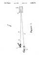
- FIG. 1is a cross-section of the complete optical layout of the mass spectrometer.
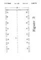
- FIG. 2is a cross-section of the ion source optics section of the mass spectrometer of FIG. 1.
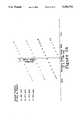
- FIG. 3is a cross-section of the ion reflector of the mass spectrometer of FIG. 1.
- FIGS. 4A and 4Bare top and side cross-sectional views of the post-acceleration ion detector of the mass spectrometer of FIG. 1.
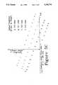
- FIGS. 5A-5Eillustrate the direction and off-axis distance of 53 different ion trajectories for einzel lens voltages of -7,500 volts, -6,400 volts, -5,000 volts 4,000 volts and -1,000 volts, respectively.
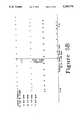
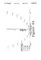
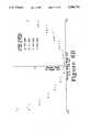
- FIGS. 6A-6Cillustrate the time-of-flight and off-axis distance of the same 53 ion trajectories for einzel lens voltages of -7,500 volts, -6,400 volts, and -1,000 volts, respectively.
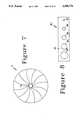
- FIG. 7illustrates an adjustable aperture diaphragm suitable for adjusting the resolution of the spectrometer.
- FIG. 8illustrates an alternate mechanism for altering the aperture size to adjust resolution.
- FIG. 1illustrates a time-of-flight mass spectrometer 10 in which the resolution of the spectrometer can be adjusted.
- Mass spectrometer 10contains 3 major components: (i) an ion source optics section 11 illustrated in greater detail in FIG. 2; (ii) an ion reflector 12 illustrated in greater detail in FIG. 3; and (iii) a post-acceleration ion detector 13 illustrated in greater detail in FIG. 4.
- the regions between these 3 major componentsare substantially field-free and the ion trajectories within such field-free regions are substantially parallel.
- source optics section 11has a diameter D 1 and a length L 1 of 101.5 and 128.0 millimeters, respectively.
- an optical lens 21focusses a narrow pulse of laser light 22 from a laser 20 onto a small region of a target 23 coated with a material under test.
- these biopolymersare coated onto target 23 within an organic matrix that exhibits strong optical absorption at the wavelength of the laser light.
- the targetcan include a substrate that is strongly absorbing to the laser light.
- this pulsehas a small temporal extent on the order of 0.5 to 5 nanoseconds so that ions are generated at the target only during a very small temporal interval.
- a timer(not shown) is activated at the time of the laser pulse and it measures the times for various types of the generated ions to reach the detector.
- the ions emitted from target 23exhibit an intensity distribution as a function of the angle ⁇ of the direction of emission relative to a normal to the front surface of the target. Only those ions that pass through a first aperture 24 in a conductive, opaque barrier 25 are included in an ion beam 14 that passes through the ion optics. Opaque barrier 25 also includes a second aperture 26 through which laser pulse 22 is focussed onto the target. Barrier 25 is grounded and target 23 is maintained at 3,000 volts by a voltage source S 1 so that target 23 and aperture 24 in barrier 25 function as an immersion lens to collect ions emitted from the target by the laser beam.
- the ions passing through aperture 24also pass through an aperture 27 in a conductive barrier 28 and an aperture 29 in a conductive barrier 210.
- Barriers 25 and 210are grounded and barrier 28 is maintained at a controlled voltage in the range -1,000 volts to -7,500 volts by a voltage source S 2 .
- Barriers 25, 28 and 210function as an einzel lens that, in conjunction with the immersion lens formed by elements 23 and 25, cooperate to focus the ions emitted from target 23 into an ion beam 14.
- ion beam 14is incident on an ion reflector 12 that reflects this beam onto a detector 13.
- the angle between an incident portion 15 of beam 14 and reflected portion 16 of this beamis 4 degrees.
- the parameters of reflector 12are chosen to compensate substantially for time-of-flight differences of identical ions resulting from kinetic energy differences of emission from the target.
- This reflectorhas a length L 2 and a height H 2 of 220 millimeters and 114 millimeters, respectively.
- This reflectoris cylindrically symmetric about an axis A and consists of a set of electrodes 31-38 maintained at voltages of 0, 500, 1,800, 2,140, 2,480, 2,820, 3,160 and 3,500 volts, respectively. These parameters are selected to maximally compensate for time-of-flight differences of identical ions emitted from target 23 at different initial kinetic energies.
- detector 13The details of detector 13 are shown in the top cross-sectional view in FIG. 4A and in the side cross-sectional view in FIG. 4B.
- the reflected portion 16 of ion beam 14enters the detector substantially parallel to an axis A'.
- the ion beamis focussed to a small spot at 40 on a rear wall of a conductor 41 that emits secondary electrons 415 in response to impact of each ion in the ion beam 16.
- the electric fields created by conductor 41 and a conductor 414direct these electrons 415 onto a fast scintillator 42 to produce photons that are detected by a photomultiplier 43.
- this particular embodimentis designed to measure mass spectra up to several hundred thousand atomic mass units (AMU) and because such high mass ions generate secondary electrons with much greater efficiency at higher energies, the ions in beam 16 are subjected within this detector to an acceleration electric field that increases their energy sufficiently to produce an adequate number of secondary electrons per incident ion.
- the electric field within this detectoris also shaped to focus the beam onto the back wall of element 41 at location 40.
- Barriers 49, 410 and 411together act as a weak einzel lens, but their purpose is to prevent entry of ions with energies of less than approximately 100 eV formed by various processes within the mass spectrometer and which would otherwise produce unwanted noise signals.
- Barrier 411, ring 412 and conductor 413function together as an accelerating lens which focusses the ion beam to a small spot at location 40.
- Barriers 48, 49 and 411are operated at ground potential.
- Barrier 410 and ring 412are biased at +200 and -4,000 volts, respectively.
- Conductor 413 and conductor 41are biased at -20,000 volts.
- Conductor 414 and scintillator 42are at ground potential (0 volts).
- Parts 48, 49, 410, 411, 412 and 413 as well as apertures 44, 45, 46 and 47are cylindrically symmetric about axis A'.
- the lateral distancei.e., the distance from axis A
- the directionrelative to axis A
- the time-of-flightwere calculated at a distance along axis A of 128 mm from target 23.
- a positive value of the product of the angular direction and the distance from the axisindicates that the ion is still converging toward the axis and a negative product indicates that such ion has crossed the axis.
- barrier 28is the biased element of the einzel lens, this voltage affects the focussing of the emitted ions by the immersion lens (elements 23 and 25) and the einzel lens (elements 25, 28 and 210).
- FIGS. 5A-5Eillustrate both the direction of the trajectory (relative to axis A) and the off-axis distance of these trajectories at 128 mm from the target.
- FIGS. 6A-6Cillustrate both the time-of-flight and the off-axis distance (at 128 mm from the target) at three different einzel lens voltage for these trajectories.
- FIGS. 5A and 6Apresent data for trajectories with a voltage of -7,500 volts on barrier 28.
- FIGS. 5B and 6Bare for a voltage of -6,400 volts
- FIG. 5Cis for a voltage of -5,000 volts
- FIG. 5Dis for a voltage of -4,000 volts
- FIGS. 5E and 6Care for a voltage of -1,000 volts.
- FIGS. 6A-6Cillustrate that the excess time-of-flight of a trajectory (i.e., the amount that the time-of-flight of a trajectory exceeds the minimal time-of-flight of any of these trajectories) varies substantially monotonically with the off-axis distance. This means that resolution can be improved by eliminating the ions that are farthest off-axis at the distance of 128 mm from the target. This can be achieved by locating at this distance an additional barrier 212 (illustrated in FIG. 2) having an aperture 213 centered on axis A.
- the diameter of aperture 213can be selected to eliminate a preselected group of the ion trajectories with greatest excess time-of-flight. For example, as illustrated in FIG. 6B, when the voltage of barrier 28 is -6,400 volts, if the radius of aperture 213 is 0.3 mm, then ions with an excess time-of-flight greater than 6 nanoseconds will be eliminated and, when the radius is 0.2 mm, ions with an excess time-of-flight greater than 3.5 nanoseconds will be eliminated.
- FIGS. 6A-6Cillustrate that for each voltage of barrier 28, the radius of this aperture can be selected to block ions with any preselected excess time-of-flight exhibited by this system.
- an adjustable aperture 213enables the controlled elimination of the longer time-of-flight ions.
- FIG. 7illustrates a conventional variable aperture diaphragm 71 such as is utilized in cameras.
- the diameter of aperture 72can be varied in this device.
- This type of variable aperturecan be utilized in barrier 212 to enable adjustment of system resolution.
- the aperture diametercan be altered by the user by means of a connecting mechanical linkage accessible by the user and connected to this adjustable diaphragm to enable variation of the aperture radius.
- a motorcan be coupled to this variable aperture diaphragm to enable electronic control of the diaphragm diameter. Both mechanical and electrical linkages are well known from the camera art.
- aperture 213will preferably be substantially circular and centered on the ion beam so that the aperture is substantially rotationally symmetric about the center of the ion beam, other shapes and alignment are acceptable as long as adjustment of the aperture dimensions and/or location function to vary the resolution.
- aperture 72is only substantially circular.
- An example of a noncircular apertureis a triangular aperture bounded by three opaque sheets each having a straight edge that defines a side of this aperture.
- such an aperturewould have the shape of an equilateral triangle so that it most closely approximates a circular aperture.
- FIG. 8An alternate mechanism 81 for varying aperture size is illustrated in FIG. 8.
- a plate 82contains a set of apertures 83-88 that decrease monotonically in radius. This plate is mounted to slide laterally across axis A such that any selected one of these apertures can be moved to center on axis A. Motion of this plate can be achieved by a mechanical linkage accessible by the user or by an electronic linkage such as a motor controlled by electrical input from the user.
- Variable aperture mechanism 71has the advantage of providing continuous variation of the radius of aperture 213.
- Variable aperture mechanism 81has the advantage that it is structurally much simpler and therefore is less susceptible to damage from the impacts of the blocked ions.
- FIGS. 6A-6Cillustrate that, for a fixed radius aperture 213, the selection of the ions to be blocked can be achieved by variation of the voltage of barrier 28 in the einzel lens.
- the selection of the ions to be blockedcan be achieved by variation of the voltage of barrier 28 in the einzel lens.
- FIG. 6Ait can be seen that, for a barrier 28 voltage of -7,500 volts, ions with excess time-of-flight greater than 14 nanoseconds are eliminated.
- FIG. 6Bit can be seen that, for a voltage of -6,400 volts on barrier 28, ions with excess time-of-flight greater than 7 nanoseconds are eliminated.
- FIG. 6Cit can be seen that, for a voltage of -1,000 volts on barrier 28, ions with excess time-of-flight greater than 3 nanoseconds are eliminated.
- the radius of aperture 213 and the voltage on barrier 28can be fixed at values that achieve a preselected value of resolution, it is advantageous to be able to adjust the resolution because this also adjusts the device sensitivity. That is, the improved resolution is achieved by rejecting those ions with an excess time-of-flight greater than some selected value. The elimination of part of the ion beam reduces the sensitivity of the measurement. Therefore, the choices of voltage on barrier 28 and the radius of aperture 213 involve a tradeoff between resolution and sensitivity. Therefore, for increased flexibility, it is advantageous to include the ability to adjust at least one parameter that controls the tradeoff between resolution and sensitivity.
Landscapes
- Chemical & Material Sciences (AREA)
- Analytical Chemistry (AREA)
- Other Investigation Or Analysis Of Materials By Electrical Means (AREA)
- Electron Tubes For Measurement (AREA)
Abstract
Description
Claims (12)
Priority Applications (5)
| Application Number | Priority Date | Filing Date | Title |
|---|---|---|---|
| US07/691,272US5300774A (en) | 1991-04-25 | 1991-04-25 | Time-of-flight mass spectrometer with an aperture enabling tradeoff of transmission efficiency and resolution |
| EP92912222AEP0587707B1 (en) | 1991-04-25 | 1992-04-23 | Time-of-flight mass spectrometer with an aperture enabling tradeoff of transmission efficiency and resolution |
| DE69230174TDE69230174T2 (en) | 1991-04-25 | 1992-04-23 | FLIGHT TIME MASS SPECTROMETER WITH AN OPENING TO COMPENSATE TRANSMISSION CAPACITY AND RESOLUTION |
| PCT/US1992/003357WO1992019367A1 (en) | 1991-04-25 | 1992-04-23 | Time-of-flight mass spectrometer with an aperture enabling tradeoff of transmission efficiency and resolution |
| JP4511915AJPH07500448A (en) | 1991-04-25 | 1992-04-23 | Time-of-flight mass spectrometer with aperture that allows performance to be balanced between resolution and transfer efficiency |
Applications Claiming Priority (1)
| Application Number | Priority Date | Filing Date | Title |
|---|---|---|---|
| US07/691,272US5300774A (en) | 1991-04-25 | 1991-04-25 | Time-of-flight mass spectrometer with an aperture enabling tradeoff of transmission efficiency and resolution |
Publications (1)
| Publication Number | Publication Date |
|---|---|
| US5300774Atrue US5300774A (en) | 1994-04-05 |
Family
ID=24775860
Family Applications (1)
| Application Number | Title | Priority Date | Filing Date |
|---|---|---|---|
| US07/691,272Expired - LifetimeUS5300774A (en) | 1991-04-25 | 1991-04-25 | Time-of-flight mass spectrometer with an aperture enabling tradeoff of transmission efficiency and resolution |
Country Status (5)
| Country | Link |
|---|---|
| US (1) | US5300774A (en) |
| EP (1) | EP0587707B1 (en) |
| JP (1) | JPH07500448A (en) |
| DE (1) | DE69230174T2 (en) |
| WO (1) | WO1992019367A1 (en) |
Cited By (34)
| Publication number | Priority date | Publication date | Assignee | Title |
|---|---|---|---|---|
| US5464985A (en)* | 1993-10-01 | 1995-11-07 | The Johns Hopkins University | Non-linear field reflectron |
| US5619034A (en)* | 1995-11-15 | 1997-04-08 | Reed; David A. | Differentiating mass spectrometer |
| US5739529A (en)* | 1994-11-29 | 1998-04-14 | Bruker-Franzen Analytik Gmbh | Device and method for the improved mass resolution of time-of-flight mass spectrometer with ion reflector |
| US5742049A (en)* | 1995-12-21 | 1998-04-21 | Bruker-Franzen Analytik Gmbh | Method of improving mass resolution in time-of-flight mass spectrometry |
| US5763875A (en)* | 1991-11-12 | 1998-06-09 | Max Planck Gesellschaft | Method and apparatus for quantitative, non-resonant photoionization of neutral particles |
| US5777324A (en)* | 1996-09-19 | 1998-07-07 | Sequenom, Inc. | Method and apparatus for maldi analysis |
| WO1998014982A3 (en)* | 1996-10-01 | 1998-08-20 | Genetrace Systems | Mass spectrometer |
| US5814813A (en)* | 1996-07-08 | 1998-09-29 | The Johns Hopkins University | End cap reflection for a time-of-flight mass spectrometer and method of using the same |
| US5825025A (en)* | 1995-11-08 | 1998-10-20 | Comstock, Inc. | Miniaturized time-of-flight mass spectrometer |
| US5994695A (en)* | 1998-05-29 | 1999-11-30 | Hewlett-Packard Company | Optical path devices for mass spectrometry |
| US6008491A (en)* | 1997-10-15 | 1999-12-28 | The United States Of America As Represented By The United States Department Of Energy | Time-of-flight SIMS/MSRI reflectron mass analyzer and method |
| DE19547949C2 (en)* | 1995-09-19 | 2000-04-06 | Bruker Daltonik Gmbh | Time of flight mass spectrometer |
| US6057543A (en)* | 1995-05-19 | 2000-05-02 | Perseptive Biosystems, Inc. | Time-of-flight mass spectrometry analysis of biomolecules |
| US6169288B1 (en)* | 1997-10-03 | 2001-01-02 | Agency Of Industrial Science & Technology, Ministry Of International Trade & Industry | Laser ablation type ion source |
| US20020063205A1 (en)* | 2000-11-29 | 2002-05-30 | Martin Green | Mass spectrometer and methods of mass spectrometry |
| US20030022225A1 (en)* | 1996-12-10 | 2003-01-30 | Monforte Joseph A. | Releasable nonvolatile mass-label molecules |
| US6660229B2 (en) | 2000-06-13 | 2003-12-09 | The Trustees Of Boston University | Use of nucleotide analogs in the analysis of oligonucleotide mixtures and in highly multiplexed nucleic acid sequencing |
| EP1215711A3 (en)* | 2000-11-29 | 2004-04-28 | Micromass UK Limited | Mass spectrometer and methods of mass spectrometry |
| US20040079878A1 (en)* | 1995-05-19 | 2004-04-29 | Perseptive Biosystems, Inc. | Time-of-flight mass spectrometry analysis of biomolecules |
| US20040084613A1 (en)* | 2001-04-03 | 2004-05-06 | Bateman Robert Harold | Mass spectrometer and method of mass spectrometry |
| US6849847B1 (en) | 1998-06-12 | 2005-02-01 | Agilent Technologies, Inc. | Ambient pressure matrix-assisted laser desorption ionization (MALDI) apparatus and method of analysis |
| US6949633B1 (en) | 1995-05-22 | 2005-09-27 | Sequenom, Inc. | Primers useful for sizing nucleic acids |
| US20060075968A1 (en)* | 2004-10-12 | 2006-04-13 | Applied Materials, Inc. | Leak detector and process gas monitor |
| US20060214103A1 (en)* | 2005-03-25 | 2006-09-28 | Pusan National University Industry-University Cooperation Foundation Of Pusan | Single-particle mass spectrometer |
| US20060255289A1 (en)* | 2005-05-13 | 2006-11-16 | Cygan Thomas R | Sample handling mechanisms and methods for mass spectometry |
| US20060255256A1 (en)* | 2005-05-13 | 2006-11-16 | Hayden Kevin M | Mass analyzer systems and methods for their operation |
| US20060273252A1 (en)* | 2005-05-13 | 2006-12-07 | Mds Inc. | Methods of operating ion optics for mass spectrometry |
| US7198893B1 (en) | 1996-11-06 | 2007-04-03 | Sequenom, Inc. | DNA diagnostics based on mass spectrometry |
| US20080149825A1 (en)* | 2006-12-14 | 2008-06-26 | Tofwerk Ag | Apparatus for mass analysis of ions |
| US7759065B2 (en) | 1995-03-17 | 2010-07-20 | Sequenom, Inc. | Mass spectrometric methods for detecting mutations in a target nucleic acid |
| US8999266B2 (en) | 2000-10-30 | 2015-04-07 | Agena Bioscience, Inc. | Method and apparatus for delivery of submicroliter volumes onto a substrate |
| US9068953B2 (en) | 2007-09-17 | 2015-06-30 | Agena Bioscience, Inc. | Integrated robotic sample transfer device |
| US20220216027A1 (en)* | 2018-11-30 | 2022-07-07 | Oxford Instruments Nanotechnology Tools Limited | Charged particle beam source, surface processing apparatus and surface processing method |
| EP3306640B1 (en)* | 2010-12-20 | 2024-04-10 | Shimadzu Corporation | Time-of-flight mass spectrometer |
Families Citing this family (5)
| Publication number | Priority date | Publication date | Assignee | Title |
|---|---|---|---|---|
| DE4322104A1 (en)* | 1993-07-02 | 1995-01-19 | Bergmann Thorald | Detector for time-of-flight mass spectrometers with low time-of-flight errors and a large aperture at the same time |
| US5654543A (en)* | 1995-11-02 | 1997-08-05 | Hewlett-Packard Company | Mass spectrometer and related method |
| GB2315362A (en)* | 1996-07-12 | 1998-01-28 | Analytical Precision Ltd | Mass spectrometers |
| US6958474B2 (en)* | 2000-03-16 | 2005-10-25 | Burle Technologies, Inc. | Detector for a bipolar time-of-flight mass spectrometer |
| GB2462065B (en)* | 2008-07-17 | 2013-03-27 | Kratos Analytical Ltd | TOF mass spectrometer for stigmatic imaging and associated method |
Citations (5)
| Publication number | Priority date | Publication date | Assignee | Title |
|---|---|---|---|---|
| US3727047A (en)* | 1971-07-22 | 1973-04-10 | Avco Corp | Time of flight mass spectrometer comprising a reflecting means which equalizes time of flight of ions having same mass to charge ratio |
| US3936693A (en)* | 1972-10-02 | 1976-02-03 | General Electric Company | Two-aperture immersion lens |
| US4107527A (en)* | 1977-07-13 | 1978-08-15 | Valentin Tikhonovich Cherepin | Ion-emission microanalyzer microscope |
| US4625112A (en)* | 1983-11-30 | 1986-11-25 | Shimadzu Corporation | Time of flight mass spectrometer |
| US4740692A (en)* | 1985-06-13 | 1988-04-26 | Mitsubishi Denki Kabushiki Kaisha | Laser mass spectroscopic analyzer and method |
Family Cites Families (3)
| Publication number | Priority date | Publication date | Assignee | Title |
|---|---|---|---|---|
| US3863068A (en)* | 1972-07-27 | 1975-01-28 | Max Planck Gesellschaft | Time-of-flight mass spectrometer |
| FR2624610B1 (en)* | 1987-12-11 | 1990-03-30 | Cameca | TIME-OF-FLIGHT, CONTINUOUSLY SCAN ANALYSIS METHOD AND ANALYSIS DEVICE FOR CARRYING OUT SAID METHOD |
| DE3920566A1 (en)* | 1989-06-23 | 1991-01-10 | Bruker Franzen Analytik Gmbh | MS-MS FLIGHT TIME MASS SPECTROMETER |
- 1991
- 1991-04-25USUS07/691,272patent/US5300774A/ennot_activeExpired - Lifetime
- 1992
- 1992-04-23DEDE69230174Tpatent/DE69230174T2/ennot_activeExpired - Fee Related
- 1992-04-23JPJP4511915Apatent/JPH07500448A/enactivePending
- 1992-04-23WOPCT/US1992/003357patent/WO1992019367A1/enactiveIP Right Grant
- 1992-04-23EPEP92912222Apatent/EP0587707B1/ennot_activeExpired - Lifetime
Patent Citations (5)
| Publication number | Priority date | Publication date | Assignee | Title |
|---|---|---|---|---|
| US3727047A (en)* | 1971-07-22 | 1973-04-10 | Avco Corp | Time of flight mass spectrometer comprising a reflecting means which equalizes time of flight of ions having same mass to charge ratio |
| US3936693A (en)* | 1972-10-02 | 1976-02-03 | General Electric Company | Two-aperture immersion lens |
| US4107527A (en)* | 1977-07-13 | 1978-08-15 | Valentin Tikhonovich Cherepin | Ion-emission microanalyzer microscope |
| US4625112A (en)* | 1983-11-30 | 1986-11-25 | Shimadzu Corporation | Time of flight mass spectrometer |
| US4740692A (en)* | 1985-06-13 | 1988-04-26 | Mitsubishi Denki Kabushiki Kaisha | Laser mass spectroscopic analyzer and method |
Cited By (58)
| Publication number | Priority date | Publication date | Assignee | Title |
|---|---|---|---|---|
| US5763875A (en)* | 1991-11-12 | 1998-06-09 | Max Planck Gesellschaft | Method and apparatus for quantitative, non-resonant photoionization of neutral particles |
| US5464985A (en)* | 1993-10-01 | 1995-11-07 | The Johns Hopkins University | Non-linear field reflectron |
| US5739529A (en)* | 1994-11-29 | 1998-04-14 | Bruker-Franzen Analytik Gmbh | Device and method for the improved mass resolution of time-of-flight mass spectrometer with ion reflector |
| US7759065B2 (en) | 1995-03-17 | 2010-07-20 | Sequenom, Inc. | Mass spectrometric methods for detecting mutations in a target nucleic acid |
| US6281493B1 (en) | 1995-05-19 | 2001-08-28 | Perseptive Biosystems, Inc. | Time-of-flight mass spectrometry analysis of biomolecules |
| US6057543A (en)* | 1995-05-19 | 2000-05-02 | Perseptive Biosystems, Inc. | Time-of-flight mass spectrometry analysis of biomolecules |
| US20040079878A1 (en)* | 1995-05-19 | 2004-04-29 | Perseptive Biosystems, Inc. | Time-of-flight mass spectrometry analysis of biomolecules |
| US6949633B1 (en) | 1995-05-22 | 2005-09-27 | Sequenom, Inc. | Primers useful for sizing nucleic acids |
| DE19547949C2 (en)* | 1995-09-19 | 2000-04-06 | Bruker Daltonik Gmbh | Time of flight mass spectrometer |
| US5825025A (en)* | 1995-11-08 | 1998-10-20 | Comstock, Inc. | Miniaturized time-of-flight mass spectrometer |
| US5619034A (en)* | 1995-11-15 | 1997-04-08 | Reed; David A. | Differentiating mass spectrometer |
| US5742049A (en)* | 1995-12-21 | 1998-04-21 | Bruker-Franzen Analytik Gmbh | Method of improving mass resolution in time-of-flight mass spectrometry |
| US5814813A (en)* | 1996-07-08 | 1998-09-29 | The Johns Hopkins University | End cap reflection for a time-of-flight mass spectrometer and method of using the same |
| US5777324A (en)* | 1996-09-19 | 1998-07-07 | Sequenom, Inc. | Method and apparatus for maldi analysis |
| US6111251A (en)* | 1996-09-19 | 2000-08-29 | Sequenom, Inc. | Method and apparatus for MALDI analysis |
| US6812455B2 (en) | 1996-09-19 | 2004-11-02 | Sequenom, Inc. | Method and apparatus for MALDI analysis |
| US6423966B2 (en) | 1996-09-19 | 2002-07-23 | Sequenom, Inc. | Method and apparatus for maldi analysis |
| US5864137A (en)* | 1996-10-01 | 1999-01-26 | Genetrace Systems, Inc. | Mass spectrometer |
| WO1998014982A3 (en)* | 1996-10-01 | 1998-08-20 | Genetrace Systems | Mass spectrometer |
| US20070202514A1 (en)* | 1996-11-06 | 2007-08-30 | Sequenom, Inc. | DNA diagnostics based on mass spectrometry |
| US20090023150A1 (en)* | 1996-11-06 | 2009-01-22 | Sequenom, Inc. | DNA Diagnostics Based on Mass Spectrometry |
| US7501251B2 (en) | 1996-11-06 | 2009-03-10 | Sequenom, Inc. | DNA diagnostics based on mass spectrometry |
| US7198893B1 (en) | 1996-11-06 | 2007-04-03 | Sequenom, Inc. | DNA diagnostics based on mass spectrometry |
| US8486623B2 (en) | 1996-12-10 | 2013-07-16 | Sequenom, Inc. | Releasable nonvolatile mass-label molecules |
| US20030022225A1 (en)* | 1996-12-10 | 2003-01-30 | Monforte Joseph A. | Releasable nonvolatile mass-label molecules |
| US6635452B1 (en) | 1996-12-10 | 2003-10-21 | Sequenom Inc. | Releasable nonvolatile mass label molecules |
| US7132519B2 (en) | 1996-12-10 | 2006-11-07 | Sequenom, Inc. | Releasable nonvolatile mass-label molecules |
| US6169288B1 (en)* | 1997-10-03 | 2001-01-02 | Agency Of Industrial Science & Technology, Ministry Of International Trade & Industry | Laser ablation type ion source |
| US6008491A (en)* | 1997-10-15 | 1999-12-28 | The United States Of America As Represented By The United States Department Of Energy | Time-of-flight SIMS/MSRI reflectron mass analyzer and method |
| US5994695A (en)* | 1998-05-29 | 1999-11-30 | Hewlett-Packard Company | Optical path devices for mass spectrometry |
| US6849847B1 (en) | 1998-06-12 | 2005-02-01 | Agilent Technologies, Inc. | Ambient pressure matrix-assisted laser desorption ionization (MALDI) apparatus and method of analysis |
| US6660229B2 (en) | 2000-06-13 | 2003-12-09 | The Trustees Of Boston University | Use of nucleotide analogs in the analysis of oligonucleotide mixtures and in highly multiplexed nucleic acid sequencing |
| US20040077004A1 (en)* | 2000-06-13 | 2004-04-22 | Cantor Charles R. | Use of nucleotide analogs in the analysis of oligonucleotide mixtures and highly multiplexed nucleic acid sequencing |
| US9669376B2 (en) | 2000-10-30 | 2017-06-06 | Agena Bioscience, Inc. | Method and apparatus for delivery of submicroliter volumes onto a substrate |
| US8999266B2 (en) | 2000-10-30 | 2015-04-07 | Agena Bioscience, Inc. | Method and apparatus for delivery of submicroliter volumes onto a substrate |
| US20040211895A1 (en)* | 2000-11-29 | 2004-10-28 | Martin Green | Mass spectrometer and methods of mass spectrometry |
| EP1460674A3 (en)* | 2000-11-29 | 2004-12-01 | Micromass UK Limited | Mass spectrometer and methods of mass spectrometry |
| EP1768164A1 (en)* | 2000-11-29 | 2007-03-28 | Micromass UK Limited | Mass spectrometer and methods of mass spectrometry |
| EP1215711A3 (en)* | 2000-11-29 | 2004-04-28 | Micromass UK Limited | Mass spectrometer and methods of mass spectrometry |
| US20020063205A1 (en)* | 2000-11-29 | 2002-05-30 | Martin Green | Mass spectrometer and methods of mass spectrometry |
| US6894275B2 (en) | 2000-11-29 | 2005-05-17 | Micromass Uk Limited | Mass spectrometer and methods of mass spectrometry |
| US6878929B2 (en) | 2000-11-29 | 2005-04-12 | Micromass Uk Limited | Mass spectrometer and methods of mass spectrometry |
| US20040084613A1 (en)* | 2001-04-03 | 2004-05-06 | Bateman Robert Harold | Mass spectrometer and method of mass spectrometry |
| US7038197B2 (en)* | 2001-04-03 | 2006-05-02 | Micromass Limited | Mass spectrometer and method of mass spectrometry |
| US20060075968A1 (en)* | 2004-10-12 | 2006-04-13 | Applied Materials, Inc. | Leak detector and process gas monitor |
| US20060214103A1 (en)* | 2005-03-25 | 2006-09-28 | Pusan National University Industry-University Cooperation Foundation Of Pusan | Single-particle mass spectrometer |
| US7365314B2 (en)* | 2005-03-25 | 2008-04-29 | Pusan National University Industry-University Cooperation Foundation | Single-particle mass spectrometer |
| US20060255256A1 (en)* | 2005-05-13 | 2006-11-16 | Hayden Kevin M | Mass analyzer systems and methods for their operation |
| US7405396B2 (en) | 2005-05-13 | 2008-07-29 | Applera Corporation | Sample handling mechanisms and methods for mass spectrometry |
| US7385186B2 (en)* | 2005-05-13 | 2008-06-10 | Applera Corporation | Methods of operating ion optics for mass spectrometry |
| US7351959B2 (en) | 2005-05-13 | 2008-04-01 | Applera Corporation | Mass analyzer systems and methods for their operation |
| US20060273252A1 (en)* | 2005-05-13 | 2006-12-07 | Mds Inc. | Methods of operating ion optics for mass spectrometry |
| US20060255289A1 (en)* | 2005-05-13 | 2006-11-16 | Cygan Thomas R | Sample handling mechanisms and methods for mass spectometry |
| US20080149825A1 (en)* | 2006-12-14 | 2008-06-26 | Tofwerk Ag | Apparatus for mass analysis of ions |
| US9068953B2 (en) | 2007-09-17 | 2015-06-30 | Agena Bioscience, Inc. | Integrated robotic sample transfer device |
| EP3306640B1 (en)* | 2010-12-20 | 2024-04-10 | Shimadzu Corporation | Time-of-flight mass spectrometer |
| US20220216027A1 (en)* | 2018-11-30 | 2022-07-07 | Oxford Instruments Nanotechnology Tools Limited | Charged particle beam source, surface processing apparatus and surface processing method |
| US12125664B2 (en)* | 2018-11-30 | 2024-10-22 | Oxford Instruments Nanotechnology Tools Limited | Charged particle beam source, surface processing apparatus and surface processing method |
Also Published As
| Publication number | Publication date |
|---|---|
| WO1992019367A1 (en) | 1992-11-12 |
| EP0587707B1 (en) | 1999-10-20 |
| DE69230174D1 (en) | 1999-11-25 |
| JPH07500448A (en) | 1995-01-12 |
| EP0587707A4 (en) | 1995-01-25 |
| DE69230174T2 (en) | 2000-06-15 |
| EP0587707A1 (en) | 1994-03-23 |
Similar Documents
| Publication | Publication Date | Title |
|---|---|---|
| US5300774A (en) | Time-of-flight mass spectrometer with an aperture enabling tradeoff of transmission efficiency and resolution | |
| US5032722A (en) | MS-MS time-of-flight mass spectrometer | |
| US6717132B2 (en) | Gridless time-of-flight mass spectrometer for orthogonal ion injection | |
| US5864137A (en) | Mass spectrometer | |
| US5128543A (en) | Particle analyzer apparatus and method | |
| US5117107A (en) | Mass spectrometer | |
| US8829428B2 (en) | Time-of-flight spectrometry and spectroscopy of surfaces | |
| US8513597B2 (en) | Atom probe | |
| EP1051732B1 (en) | Time-of-flight mass spectrometer | |
| US20080272289A1 (en) | Linear tof geometry for high sensitivity at high mass | |
| US7633059B2 (en) | Mass spectrometry system having ion deflector | |
| JP2017511577A (en) | Multiple reflection time-of-flight mass spectrometer with axial pulse transducer. | |
| US5665967A (en) | Apparatus and method for surface analysis | |
| EP1721330A2 (en) | Focal plane detector assembly of a mass spectrometer | |
| US6674069B1 (en) | In-line reflecting time-of-flight mass spectrometer for molecular structural analysis using collision induced dissociation | |
| US4146787A (en) | Methods and apparatus for energy analysis and energy filtering of secondary ions and electrons | |
| Schueler | Time-of-flight mass analysers | |
| EP0456516B1 (en) | Ion buncher | |
| KR20230011409A (en) | Apparatus and method for high performance charged particle detection | |
| EP0551999A1 (en) | Mass spectrometry systems | |
| US9754772B2 (en) | Charged particle image measuring device and imaging mass spectrometry apparatus | |
| US6642637B1 (en) | Parallel plate electron multiplier | |
| WO2000036633A1 (en) | In-line reflecting time-of-flight mass spectrometer for molecular structural analysis using collision induced dissociation | |
| JP3581269B2 (en) | Vertical acceleration time-of-flight mass spectrometer | |
| WO2006134380A2 (en) | Atom probe |
Legal Events
| Date | Code | Title | Description |
|---|---|---|---|
| AS | Assignment | Owner name:APPLIED BIOSYSTEMS, CALIFORNIA Free format text:ASSIGNMENT OF ASSIGNORS INTEREST.;ASSIGNOR:BUTTRILL, S. E., JR.;REEL/FRAME:005692/0325 Effective date:19910422 | |
| STCF | Information on status: patent grant | Free format text:PATENTED CASE | |
| AS | Assignment | Owner name:PERKIN ELMER CORPORATION, THE Free format text:MERGER;ASSIGNOR:APPLIED BIOSYSTEMS, INC.;REEL/FRAME:007408/0429 Effective date:19950214 | |
| FEPP | Fee payment procedure | Free format text:PAYOR NUMBER ASSIGNED (ORIGINAL EVENT CODE: ASPN); ENTITY STATUS OF PATENT OWNER: LARGE ENTITY | |
| FPAY | Fee payment | Year of fee payment:4 | |
| FPAY | Fee payment | Year of fee payment:8 | |
| AS | Assignment | Owner name:PE CORPORATION (NY), CALIFORNIA Free format text:CHANGE OF NAME;ASSIGNOR:PERKIN-ELMER CORPORATION, THE;REEL/FRAME:012676/0767 Effective date:20000522 | |
| AS | Assignment | Owner name:APPLERA CORPORATION, CALIFORNIA Free format text:ASSIGNMENT OF ASSIGNORS INTEREST;ASSIGNOR:PE CORPORATION (NY);REEL/FRAME:013563/0534 Effective date:20020628 | |
| AS | Assignment | Owner name:MDS INC. (THROUGH ITS MDS SCIEX DIVISION), CANADA Free format text:ASSIGNMENT OF ASSIGNORS INTEREST;ASSIGNOR:APPLERA CORPORATION (THROUGH ITS APPLIED BIOSYSTEMS GROP);REEL/FRAME:015452/0203 Effective date:20041022 | |
| FPAY | Fee payment | Year of fee payment:12 | |
| AS | Assignment | Owner name:BANK OF AMERICA, N.A, AS COLLATERAL AGENT, WASHING Free format text:SECURITY AGREEMENT;ASSIGNOR:APPLIED BIOSYSTEMS, LLC;REEL/FRAME:021976/0001 Effective date:20081121 Owner name:BANK OF AMERICA, N.A, AS COLLATERAL AGENT,WASHINGT Free format text:SECURITY AGREEMENT;ASSIGNOR:APPLIED BIOSYSTEMS, LLC;REEL/FRAME:021976/0001 Effective date:20081121 | |
| AS | Assignment | Owner name:APPLIED BIOSYSTEMS, LLC., CALIFORNIA Free format text:MERGER;ASSIGNOR:PERSEPTIVE BIOSYSTEMS, INC.;REEL/FRAME:023839/0669 Effective date:20090407 | |
| AS | Assignment | Owner name:APPLIED BIOSYSTEMS, LLC,CALIFORNIA Free format text:RELEASE BY SECURED PARTY;ASSIGNOR:BANK OF AMERICA, N.A.;REEL/FRAME:024160/0955 Effective date:20100129 Owner name:APPLIED BIOSYSTEMS, LLC, CALIFORNIA Free format text:RELEASE BY SECURED PARTY;ASSIGNOR:BANK OF AMERICA, N.A.;REEL/FRAME:024160/0955 Effective date:20100129 | |
| AS | Assignment | Owner name:APPLIED BIOSYSTEMS, INC., CALIFORNIA Free format text:LIEN RELEASE;ASSIGNOR:BANK OF AMERICA, N.A.;REEL/FRAME:030182/0677 Effective date:20100528 | |
| AS | Assignment | Owner name:APPLIED BIOSYSTEMS, LLC, CALIFORNIA Free format text:CORRECTIVE ASSIGNMENT TO CORRECT THE RECEIVING PARTY NAME PREVIOUSLY RECORDED AT REEL: 030182 FRAME: 0712. ASSIGNOR(S) HEREBY CONFIRMS THE ASSIGNMENT;ASSIGNOR:BANK OF AMERICA, N.A.;REEL/FRAME:038026/0430 Effective date:20100528 Owner name:APPLIED BIOSYSTEMS, LLC, CALIFORNIA Free format text:CORRECTIVE ASSIGNMENT TO CORRECT THE RECEIVING PARTY NAME PREVIOUSLY RECORDED AT REEL: 030182 FRAME: 0677. ASSIGNOR(S) HEREBY CONFIRMS THE ASSIGNMENT;ASSIGNOR:BANK OF AMERICA, N.A.;REEL/FRAME:038026/0430 Effective date:20100528 |