US5300456A - Metal-to-metal antifuse structure - Google Patents
Metal-to-metal antifuse structureDownload PDFInfo
- Publication number
- US5300456A US5300456AUS08/079,194US7919493AUS5300456AUS 5300456 AUS5300456 AUS 5300456AUS 7919493 AUS7919493 AUS 7919493AUS 5300456 AUS5300456 AUS 5300456A
- Authority
- US
- United States
- Prior art keywords
- layer
- antifuse
- metal
- oxide
- dielectric layer
- Prior art date
- Legal status (The legal status is an assumption and is not a legal conclusion. Google has not performed a legal analysis and makes no representation as to the accuracy of the status listed.)
- Expired - Lifetime
Links
Images

Classifications
- H—ELECTRICITY
- H01—ELECTRIC ELEMENTS
- H01L—SEMICONDUCTOR DEVICES NOT COVERED BY CLASS H10
- H01L21/00—Processes or apparatus adapted for the manufacture or treatment of semiconductor or solid state devices or of parts thereof
- H01L21/70—Manufacture or treatment of devices consisting of a plurality of solid state components formed in or on a common substrate or of parts thereof; Manufacture of integrated circuit devices or of parts thereof
- H01L21/71—Manufacture of specific parts of devices defined in group H01L21/70
- H01L21/768—Applying interconnections to be used for carrying current between separate components within a device comprising conductors and dielectrics
- H01L21/76838—Applying interconnections to be used for carrying current between separate components within a device comprising conductors and dielectrics characterised by the formation and the after-treatment of the conductors
- H01L21/76886—Modifying permanently or temporarily the pattern or the conductivity of conductive members, e.g. formation of alloys, reduction of contact resistances
- H01L21/76888—By rendering at least a portion of the conductor non conductive, e.g. oxidation
- H—ELECTRICITY
- H01—ELECTRIC ELEMENTS
- H01L—SEMICONDUCTOR DEVICES NOT COVERED BY CLASS H10
- H01L23/00—Details of semiconductor or other solid state devices
- H01L23/52—Arrangements for conducting electric current within the device in operation from one component to another, i.e. interconnections, e.g. wires, lead frames
- H01L23/522—Arrangements for conducting electric current within the device in operation from one component to another, i.e. interconnections, e.g. wires, lead frames including external interconnections consisting of a multilayer structure of conductive and insulating layers inseparably formed on the semiconductor body
- H01L23/525—Arrangements for conducting electric current within the device in operation from one component to another, i.e. interconnections, e.g. wires, lead frames including external interconnections consisting of a multilayer structure of conductive and insulating layers inseparably formed on the semiconductor body with adaptable interconnections
- H01L23/5252—Arrangements for conducting electric current within the device in operation from one component to another, i.e. interconnections, e.g. wires, lead frames including external interconnections consisting of a multilayer structure of conductive and insulating layers inseparably formed on the semiconductor body with adaptable interconnections comprising anti-fuses, i.e. connections having their state changed from non-conductive to conductive
- H—ELECTRICITY
- H01—ELECTRIC ELEMENTS
- H01L—SEMICONDUCTOR DEVICES NOT COVERED BY CLASS H10
- H01L2924/00—Indexing scheme for arrangements or methods for connecting or disconnecting semiconductor or solid-state bodies as covered by H01L24/00
- H01L2924/0001—Technical content checked by a classifier
- H01L2924/0002—Not covered by any one of groups H01L24/00, H01L24/00 and H01L2224/00
- Y—GENERAL TAGGING OF NEW TECHNOLOGICAL DEVELOPMENTS; GENERAL TAGGING OF CROSS-SECTIONAL TECHNOLOGIES SPANNING OVER SEVERAL SECTIONS OF THE IPC; TECHNICAL SUBJECTS COVERED BY FORMER USPC CROSS-REFERENCE ART COLLECTIONS [XRACs] AND DIGESTS
- Y10—TECHNICAL SUBJECTS COVERED BY FORMER USPC
- Y10S—TECHNICAL SUBJECTS COVERED BY FORMER USPC CROSS-REFERENCE ART COLLECTIONS [XRACs] AND DIGESTS
- Y10S148/00—Metal treatment
- Y10S148/055—Fuse
Definitions
- This inventiongenerally relates to antifuse cells and more specifically to metal-to-metal antifuse structures.
- Antifuse cellsconventionally comprise a decoupling element, such as a PN junction diode, and an antifuse element electrically connected in series with a blocking element. Initially, the antifuse exists in a nonconductive state. To program the memory cell, a voltage is selectively impressed across it to activate the antifuse (off state) and thereafter cause the antifuse to exist in a high conductive state (on state).
- a decoupling elementsuch as a PN junction diode
- One prior art constructionis a memory cell having an antifuse element comprising amorphous silicon interposed between Titanium-Tungsten (TiW) electrodes in a Via type structure.
- TiWTitanium-Tungsten
- the bottom TiWis deposited and then buried under oxide dielectric.
- a Via openingis then etched through the oxide stopping on the bottom TiW layer,
- Amorphous siliconis then deposited into the Via opening and a top TiW electrode layer deposited and etched.
- the breakdown voltage of the antifuseis very sensitive to both the size of the antifuse opening and also the depth. The voltage depends upon the thickness of the amorphous silicon in the bottom of the via hole and this thickness varies with antifuse opening size and the depth of the via hole.
- the second problemis that the Via antifuse structure is not very scalable to smaller dimensions. As the technology scales to smaller design rules the antifuse opening must become smaller so the aspect ratio increases. Amorphous silicon is a PECVD (plasma enhanced chemical vapor deposition) process. Because of step coverage problems it becomes increasingly difficult to get the PECVD film into the bottom of deeper openings. The following disclosure overcomes both these issues.
- PECVDplasma enhanced chemical vapor deposition
- a method of forming an antifuse structure on a semiconductor deviceis disclosed.
- a first conducting layeris deposited on the semiconductor device.
- a dielectric layeris deposited over the first conducting layer.
- the dielectric layermay comprise amorphous silicon.
- An etchstop layeris then deposited over the dielectric layer.
- the etchstop layermay, for example, comprise a layer of oxide and a layer of amorphous silicon.
- the etchstop layer, dielectric layer, and first conducting layerare etched to form an antifuse stack.
- an interlevel oxideis deposited. Vias are etched in the interlevel dielectric layer to expose a portion of the first conducting layer and a portion of the antifuse stack.
- One viaextends through the interlevel dielectric layer to the semiconductor device and another via, the antifuse via, extends through the interlevel dielectric layer to the antifuse stack.
- the portion of the etchstop layer located in the antifuse viais removed to expose a portion of the dielectric layer.
- a second conducting layeris deposited over the interlevel dielectric layer, the exposed portion of the first conducting layer and the exposed portion of the dielectric layer such that the second conducting layer fills the vias.
- the second conducting layeris then etched to form the desired interconnections.
- An advantage of the inventionis providing antifuse structures having reduced variation in breakdown voltage, because the antifuse dielectric is deposited on a flat conducting layer as opposed to deposition in a via hole as in the prior art.
- a further advantage of the inventionis providing a method of forming an antifuse structure that can etch through various thickness of ILO without damaging the antifuse dielectric.
- a further advantage of the inventionis providing a metal-to-metal antifuse structure having a minimum size.
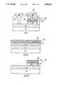
- FIG. 1is a cross-sectional diagram of a metal-to-metal antifuse structure according to the first preferred embodiment of the invention
- FIGS. 2a-eare cross-sectional diagrams of the structure of FIG. 1 at various stages of fabrication
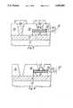
- FIG. 3is a cross-sectional diagram of a metal-to-metal antifuse structure according to the second preferred embodiment of the invention.
- FIG. 4is a cross-sectional diagram of an alternative second preferred embodiment of the invention showing a recessed aluminum layer and sidewall.
- CMOScomplementary metal-oxide-semiconductor
- BiCMOScomplementary metal-oxide-semiconductor
- the preferred embodimentswill be described as formed on a semiconductor device after the formation of transistors and the like and after the formation of the second metal interconnect level. It will be apparent to those skilled in the art that the invention may instead be formed after any conducting or interconnect layer, such as the first metal interconnect level.
- Antifuse 52is located above device 10.
- Device 10may, for example, be a CMOS device processed through the deposition of METAL 2 (shown here as metal interconnect layer 12) and may contain, for example, transistors and other elements.
- Inter-level oxide layer 36insulates portions of metal interconnect layer 12 where interconnections are not desired.
- Antifuse 52comprises conducting layer 16, dielectric layer 20, and metal interconnect layer 48.
- Conducting layer 16may, for example, comprise titanium-tungsten (TiW), titanium-nitride (TiN), or titanium (Ti). It serves as the bottom plate of antifuse 52.
- Dielectric layer 20serves as the antifuse dielectric and may, for example comprise amorphous silicon.
- Interconnect layer 48contacts antifuse stack 32 through antifuse via 44.
- Interconnect layer 48also forms the top plate of the antifuse 52.
- the electrical size of an antifuseis determined by the minimum geometry of the structure. In this case, the electrical size is determined by the diameter of antifuse via 44. A small electrical size is desired because a larger electrical size results in higher capacitance. The amount of capacitance determines the antifuse charge-up time. As the capacitance increases so does the charge-up time.
- Conducting layer 16, dielectric layer 20, oxide layer 24 and amorphous silicon layer 28form antifuse stack 32. The reasons for forming antifuse stack 32 are process related and will be described herein below.
- metal interconnect layer 12is the second interconnect level commonly referred to as Metal 2 in semiconductor processing and device 10 may comprise transistors (not shown) and other elements (also not shown) found in a typical CMOS device.
- conducting layer 16comprises titanium-tungsten (TiW).
- conducting layer 16may comprise any metal which does not react with amorphous silicon or aluminum-silicon-copper (AlSiCu), such as titanium-nitride (TiN).
- Conducting layer 16will form the bottom plate of the antifuse. It should be noted that conducting layer 16 and metal interconnect layer 12 may both comprise TiW and may be combined to form a barrier layer.
- dielectric layer 20is deposited, for example by plasma enhanced chemical vapor deposition (PECVD), to a thickness of 1000 ⁇ .
- dielectric layer 20comprises amorphous silicon.
- oxide layer 24may also be deposited by PECVD and may have a thickness on the order to 500 ⁇ .
- a second layer of amorphous silicon 28is deposited, preferably by PECVD, to a thickness on the order of 500 ⁇ . Oxide layer 24 and amorphous silicon layer 28 are dummy processing layers that have no electrical function in the antifuse. Referring to FIG.
- conducting layer 16dielectric layer 20, oxide layer 24 and amorphous silicon layer 28 are patterned and etched by conventional techniques to form the antifuse stack 32. It should be noted that at this point metal interconnect layer 12 may be patterned and etched (not shown) to form the interconnections desired for device 10.
- interlevel oxide (ILO) 36is deposited and planarized by conventional techniques.
- ILO 36is patterned and selectively etched to form via 40 and antifuse via 44.
- Via 40will extend through ILO 36 to metal interconnect layer 12.
- the antifuse via 44will extend through ILO 36 to amorphous silicon layer 28.
- a portion of amorphous silicon layer 28will be removed.
- variations in the thickness of ILO 36will result in damage to amorphous silicon layer 28 and not to the antifuse dielectric, dielectric layer 20.
- amorphous silicon layer 28is selectively etched away at the bottom of the antifuse via 44. This etch is selective relative to oxide such that the etch stops on oxide layer 24. Such etches are well known in the art.
- oxide layer 24is etched to remove the portion of oxide layer 24 at the bottom of the antifuse via 44. Because oxide layer 24 is relatively thin and of constant and known thickness, only minimal damage to dielectric layer 20 occurs.
- interconnect layer 48is deposited over the surface of the structure, as shown in FIG. 2e. Interconnect layer 48 extends through via 40 to make contact to metal interconnect layer 12 and through antifuse via 44 to dielectric layer 20. Finally, interconnect layer 48 is patterned and etched as shown in FIG. 1.
- FIG. 3is identical to FIG. 1 except that oxide layer 24 and amorphous silicon layer 28 are replaced with conductor layer 56.
- Conductor layer 56preferably comprises aluminum or aluminum-oxide, but may comprise any material which forms a good etchstop layer relative to oxide at a thickness on the order of 100 ⁇ .
- the structure of FIG. 3may be formed as described above relative to FIGS. 2a-f with a deposition of conductor metal replacing the deposition of oxide layer 24 and amorphous silicon layer 28. If aluminum-oxide is desired, it may be deposited by the sputter deposition of aluminum-oxide or by depositing aluminum and the oxidizing it.
- conductor layer 56comprises aluminum
- conductor layer 56 at the bottom of antifuse via 44may be turned into an insulator by either heating the device to a temperature of about 400° C. or via a chemical reaction with the top of the dielectric layer 20.
- the etch of conductor layer 56may be extended until the edges of conductor layer are recessed away from the antifuse via 44, as shown in FIG. 4. This may be followed by the formation of sidewall oxides 58 to isolate conductor layer 56 from metal interconnect layer 48.
Landscapes
- Engineering & Computer Science (AREA)
- Physics & Mathematics (AREA)
- Condensed Matter Physics & Semiconductors (AREA)
- General Physics & Mathematics (AREA)
- Computer Hardware Design (AREA)
- Microelectronics & Electronic Packaging (AREA)
- Power Engineering (AREA)
- Manufacturing & Machinery (AREA)
- Internal Circuitry In Semiconductor Integrated Circuit Devices (AREA)
- Design And Manufacture Of Integrated Circuits (AREA)
Abstract
Description
This invention generally relates to antifuse cells and more specifically to metal-to-metal antifuse structures.
Antifuse cells conventionally comprise a decoupling element, such as a PN junction diode, and an antifuse element electrically connected in series with a blocking element. Initially, the antifuse exists in a nonconductive state. To program the memory cell, a voltage is selectively impressed across it to activate the antifuse (off state) and thereafter cause the antifuse to exist in a high conductive state (on state).
One prior art construction is a memory cell having an antifuse element comprising amorphous silicon interposed between Titanium-Tungsten (TiW) electrodes in a Via type structure. To build this structure, the bottom TiW is deposited and then buried under oxide dielectric. A Via opening is then etched through the oxide stopping on the bottom TiW layer, Amorphous silicon is then deposited into the Via opening and a top TiW electrode layer deposited and etched. There are two difficulties with this method. First the breakdown voltage of the antifuse is very sensitive to both the size of the antifuse opening and also the depth. The voltage depends upon the thickness of the amorphous silicon in the bottom of the via hole and this thickness varies with antifuse opening size and the depth of the via hole. The second problem is that the Via antifuse structure is not very scalable to smaller dimensions. As the technology scales to smaller design rules the antifuse opening must become smaller so the aspect ratio increases. Amorphous silicon is a PECVD (plasma enhanced chemical vapor deposition) process. Because of step coverage problems it becomes increasingly difficult to get the PECVD film into the bottom of deeper openings. The following disclosure overcomes both these issues.
Generally, and in one form of the invention, a method of forming an antifuse structure on a semiconductor device is disclosed. A first conducting layer is deposited on the semiconductor device. A dielectric layer is deposited over the first conducting layer. The dielectric layer may comprise amorphous silicon. An etchstop layer is then deposited over the dielectric layer. The etchstop layer may, for example, comprise a layer of oxide and a layer of amorphous silicon. Next, the etchstop layer, dielectric layer, and first conducting layer are etched to form an antifuse stack. Next, an interlevel oxide is deposited. Vias are etched in the interlevel dielectric layer to expose a portion of the first conducting layer and a portion of the antifuse stack. One via extends through the interlevel dielectric layer to the semiconductor device and another via, the antifuse via, extends through the interlevel dielectric layer to the antifuse stack. The portion of the etchstop layer located in the antifuse via is removed to expose a portion of the dielectric layer. Next, a second conducting layer is deposited over the interlevel dielectric layer, the exposed portion of the first conducting layer and the exposed portion of the dielectric layer such that the second conducting layer fills the vias. The second conducting layer is then etched to form the desired interconnections.
An advantage of the invention is providing antifuse structures having reduced variation in breakdown voltage, because the antifuse dielectric is deposited on a flat conducting layer as opposed to deposition in a via hole as in the prior art.
A further advantage of the invention is providing a method of forming an antifuse structure that can etch through various thickness of ILO without damaging the antifuse dielectric.
A further advantage of the invention is providing a metal-to-metal antifuse structure having a minimum size.
These and other advantages will be apparent to those of ordinary skill in the art having reference to this specification in conjunction with the drawings.
In the drawings:
FIG. 1 is a cross-sectional diagram of a metal-to-metal antifuse structure according to the first preferred embodiment of the invention;
FIGS. 2a-e are cross-sectional diagrams of the structure of FIG. 1 at various stages of fabrication;
FIG. 3 is a cross-sectional diagram of a metal-to-metal antifuse structure according to the second preferred embodiment of the invention; and
FIG. 4 is a cross-sectional diagram of an alternative second preferred embodiment of the invention showing a recessed aluminum layer and sidewall.
Corresponding numerals and symbols in the different figures refer to corresponding parts unless otherwise indicated.
The preferred embodiments of the invention will be described in conjunction with a CMOS process. It will be apparent to those skilled in the art that the invention may be used with other processes, such as BiCMOS processes, which may also realize the benefits thereof. The preferred embodiments will be described as formed on a semiconductor device after the formation of transistors and the like and after the formation of the second metal interconnect level. It will be apparent to those skilled in the art that the invention may instead be formed after any conducting or interconnect layer, such as the first metal interconnect level.
A metal-to-metal antifuse according to the first preferred embodiment of the invention is shown in FIG. 1. Antifuse 52 is located abovedevice 10.Device 10 may, for example, be a CMOS device processed through the deposition of METAL 2 (shown here as metal interconnect layer 12) and may contain, for example, transistors and other elements.Inter-level oxide layer 36 insulates portions ofmetal interconnect layer 12 where interconnections are not desired.Antifuse 52 comprises conductinglayer 16,dielectric layer 20, andmetal interconnect layer 48. Conductinglayer 16 may, for example, comprise titanium-tungsten (TiW), titanium-nitride (TiN), or titanium (Ti). It serves as the bottom plate ofantifuse 52.Dielectric layer 20 serves as the antifuse dielectric and may, for example comprise amorphous silicon.Interconnect layer 48 contacts antifuse stack 32 through antifuse via 44.Interconnect layer 48 also forms the top plate of theantifuse 52. The electrical size of an antifuse is determined by the minimum geometry of the structure. In this case, the electrical size is determined by the diameter of antifuse via 44. A small electrical size is desired because a larger electrical size results in higher capacitance. The amount of capacitance determines the antifuse charge-up time. As the capacitance increases so does the charge-up time. Conductinglayer 16,dielectric layer 20,oxide layer 24 andamorphous silicon layer 28form antifuse stack 32. The reasons for formingantifuse stack 32 are process related and will be described herein below.
Referring to FIG. 2a, the formation of the first preferred embodiment of the invention begins with depositing a layer of conductingmaterial 16 to a thickness of approximately 3000 Å overmetal interconnect layer 12, which in turn coversdevice 10. As discusses above,metal interconnect layer 12 is the second interconnect level commonly referred to as Metal 2 in semiconductor processing anddevice 10 may comprise transistors (not shown) and other elements (also not shown) found in a typical CMOS device. Preferably, conductinglayer 16 comprises titanium-tungsten (TiW). However, conductinglayer 16 may comprise any metal which does not react with amorphous silicon or aluminum-silicon-copper (AlSiCu), such as titanium-nitride (TiN). Conductinglayer 16 will form the bottom plate of the antifuse. It should be noted that conductinglayer 16 andmetal interconnect layer 12 may both comprise TiW and may be combined to form a barrier layer.
Next, a layer ofdielectric material 20 is deposited, for example by plasma enhanced chemical vapor deposition (PECVD), to a thickness of 1000 Å. In the preferred embodiment,dielectric layer 20 comprises amorphous silicon. However, it will be apparent to those skilled in the art that other dielectrics may alternatively be used. This is followed with a deposition ofoxide layer 24.Oxide layer 24 may also be deposited by PECVD and may have a thickness on the order to 500 Å. Finally, a second layer ofamorphous silicon 28 is deposited, preferably by PECVD, to a thickness on the order of 500 Å.Oxide layer 24 andamorphous silicon layer 28 are dummy processing layers that have no electrical function in the antifuse. Referring to FIG. 2b, conductinglayer 16,dielectric layer 20,oxide layer 24 andamorphous silicon layer 28 are patterned and etched by conventional techniques to form theantifuse stack 32. It should be noted that at this pointmetal interconnect layer 12 may be patterned and etched (not shown) to form the interconnections desired fordevice 10.
Referring to FIG. 2c, interlevel oxide (ILO) 36 is deposited and planarized by conventional techniques. Next,ILO 36 is patterned and selectively etched to form via 40 and antifuse via 44. Via 40 will extend throughILO 36 tometal interconnect layer 12. The antifuse via 44 will extend throughILO 36 toamorphous silicon layer 28. The oxide etch stops onamorphous silicon layer 28. However, a portion ofamorphous silicon layer 28 will be removed. Thus, variations in the thickness ofILO 36 will result in damage toamorphous silicon layer 28 and not to the antifuse dielectric,dielectric layer 20.
Referring to FIG. 2d,amorphous silicon layer 28 is selectively etched away at the bottom of the antifuse via 44. This etch is selective relative to oxide such that the etch stops onoxide layer 24. Such etches are well known in the art. Next,oxide layer 24 is etched to remove the portion ofoxide layer 24 at the bottom of the antifuse via 44. Becauseoxide layer 24 is relatively thin and of constant and known thickness, only minimal damage todielectric layer 20 occurs. Next,interconnect layer 48 is deposited over the surface of the structure, as shown in FIG. 2e.Interconnect layer 48 extends through via 40 to make contact tometal interconnect layer 12 and through antifuse via 44 todielectric layer 20. Finally,interconnect layer 48 is patterned and etched as shown in FIG. 1.
A metal-to-metal antifuse according to a second preferred embodiment of the invention is shown in FIG. 3. FIG. 3 is identical to FIG. 1 except thatoxide layer 24 andamorphous silicon layer 28 are replaced withconductor layer 56.Conductor layer 56 preferably comprises aluminum or aluminum-oxide, but may comprise any material which forms a good etchstop layer relative to oxide at a thickness on the order of 100 Å. The structure of FIG. 3 may be formed as described above relative to FIGS. 2a-f with a deposition of conductor metal replacing the deposition ofoxide layer 24 andamorphous silicon layer 28. If aluminum-oxide is desired, it may be deposited by the sputter deposition of aluminum-oxide or by depositing aluminum and the oxidizing it. Alternatively, ifconductor layer 56 comprises aluminum, afterconductor layer 56 at the bottom of antifuse via 44 is etched it may be turned into an insulator by either heating the device to a temperature of about 400° C. or via a chemical reaction with the top of thedielectric layer 20. In another method, the etch ofconductor layer 56 may be extended until the edges of conductor layer are recessed away from the antifuse via 44, as shown in FIG. 4. This may be followed by the formation ofsidewall oxides 58 to isolateconductor layer 56 frommetal interconnect layer 48.
A few preferred embodiments have been described in detail hereinabove. It is to be understood that the scope of the invention also comprehends embodiments different from those described, yet within the scope of the claims.
While this invention has been described with reference to illustrative embodiments, this description is not intended to be construed in a limiting sense. Various modifications and combinations of the illustrative embodiments, as well as other embodiments of the invention, will be apparent to persons skilled in the art upon reference to the description. It is therefore intended that the appended claims encompass any such modifications or embodiments.
Claims (18)
1. A method of forming an antifuse structure on a semiconductor device comprising the steps of:
a. depositing a first layer of conducting material on said semiconductor device;
b. depositing a dielectric layer over said first conducting layer;
c. depositing an etchstop layer over said dielectric layer;
d. etching said etchstop layer, said dielectric layer, and said first metal layer to form an antifuse stack;
e. depositing a layer of interlevel oxide over said antifuse stack and said semiconductor device;
f. etching an antifuse via in said interlevel dielectric layer to expose a portion of said antifuse stack, wherein said antifuse via extends through said interlevel dielectric layer to said antifuse stack;
g. removing a portion of said etchstop layer located at said antifuse via to expose a portion of said dielectric layer;
h. depositing a second layer of conducting material over said interlevel dielectric layer, and said exposed portion of said dielectric layer such that said second conducting layer fills said antifuse via; and
i. etching said second conducting layer.
2. The method of claim 1, wherein said step of forming said etchstop layer comprises depositing a layer of aluminum-oxide to a thickness on the order of 100 Å.
3. The method of claim 1, wherein said step of forming said etchstop layer comprises depositing a layer oxide over said dielectric layer and depositing a layer of amorphous silicon over said oxide layer.
4. The method of claim 3, wherein said oxide layer has a thickness on the order of 500 Å and said amorphous silicon layer has a thickness on the order of 500 Å.
5. The method of claim 3, wherein said step of removing a portion of said etchstop layer comprises the steps of:
a. etching said layer of amorphous silicon stopping on said oxide layer; and
b. etching said layer of oxide.
6. The method of claim 1, wherein said step of forming said etchstop layer comprises depositing a layer of aluminum.
7. The method of claim 6, further comprising the step of oxidizing said layer of aluminum to form aluminum-oxide.
8. The method of claim 7, wherein said removing a portion of said etchstop layer also comprises removing a second portion of said etchstop layer located below said interlevel dielectric layer.
9. The method of claim 8, further comprising the step of forming sidewall oxides on sidewalls of said antifuse via adjacent said etchstop layer.
10. The method of claim 6, further comprising the step of converting said aluminum layer to an insulator after said step of removing a portion of said etchstop layer.
11. The method of claim 1, wherein said first and second conducting layers comprise titanium-tungsten.
12. The method of claim 1, wherein said first conducting layer comprises a metal which is operable to act as a barrier between amorphous silicon and aluminum-silicon copper.
13. The method of claim 1, wherein said dielectric layer comprises amorphous silicon.
14. A method of forming a metal-to-metal antifuse structure on a semiconductor device comprising the steps of:
a. depositing a first layer of metal on said semiconductor device, wherein said first metal layer comprises a metal that will not react with amorphous silicon or aluminum-silicon-copper;
b. depositing a dielectric layer over said first metal layer, wherein said dielectric layer comprises amorphous silicon;
c. depositing a layer of oxide over said dielectric layer;
d. depositing a layer of amorphous silicon over said oxide layer
e. etching said amorphous silicon layer, said oxide layer, said dielectric layer, and said first metal layer to form an antifuse stack;
f. depositing a layer of interlevel oxide over said antifuse stack and said semiconductor device;
g. etching a first and a second via in said interlevel dielectric layer to expose a portion of said semiconductor device and a portion of said antifuse stack, wherein said first via extends through said interlevel dielectric layer to said semiconductor device and said second via extends through said interlevel dielectric layer to said antifuse stack;
h. etching a portion of said amorphous silicon layer located at said second via to expose a portion of said oxide layer;
i. etching a portion of said oxide layer located at said second via to expose a portion of said dielectric layer;
j. depositing a second layer of metal over said interlevel dielectric layer, said exposed portion of said semiconductor device and said exposed portion of said dielectric layer such that said second metal layer fills said first and second vias; and
k. etching said second metal layer.
15. The method of claim 14, wherein said oxide layer has a thickness on the order of 500 Å and said amorphous silicon layer has a thickness on the order of 500 Å.
16. The method of claim 14, wherein said first and second layers of metal comprises titanium-tungsten.
17. The method of claim 14, wherein said first and second layers of metal comprises titanium-nitride.
18. The method of claim 14, wherein:
a. said first metal layer has a thickness on the order of 3000 Å;
b. said dielectric layer has a thickness on the order of 1000 Å;
c. said oxide layer has a thickness on the order of 500 Å; and
d. said amorphous silicon layer has a thickness on the order of 500 Å.
Priority Applications (3)
| Application Number | Priority Date | Filing Date | Title |
|---|---|---|---|
| US08/079,194US5300456A (en) | 1993-06-17 | 1993-06-17 | Metal-to-metal antifuse structure |
| US08/166,429US5451810A (en) | 1993-06-17 | 1993-12-14 | Metal-to-metal antifuse structure |
| JP6135931AJPH07142585A (en) | 1993-06-17 | 1994-06-17 | Formation of anti-fuse structure on semiconductor device and structure thereof |
Applications Claiming Priority (1)
| Application Number | Priority Date | Filing Date | Title |
|---|---|---|---|
| US08/079,194US5300456A (en) | 1993-06-17 | 1993-06-17 | Metal-to-metal antifuse structure |
Related Child Applications (1)
| Application Number | Title | Priority Date | Filing Date |
|---|---|---|---|
| US08/166,429DivisionUS5451810A (en) | 1993-06-17 | 1993-12-14 | Metal-to-metal antifuse structure |
Publications (1)
| Publication Number | Publication Date |
|---|---|
| US5300456Atrue US5300456A (en) | 1994-04-05 |
Family
ID=22149024
Family Applications (2)
| Application Number | Title | Priority Date | Filing Date |
|---|---|---|---|
| US08/079,194Expired - LifetimeUS5300456A (en) | 1993-06-17 | 1993-06-17 | Metal-to-metal antifuse structure |
| US08/166,429Expired - LifetimeUS5451810A (en) | 1993-06-17 | 1993-12-14 | Metal-to-metal antifuse structure |
Family Applications After (1)
| Application Number | Title | Priority Date | Filing Date |
|---|---|---|---|
| US08/166,429Expired - LifetimeUS5451810A (en) | 1993-06-17 | 1993-12-14 | Metal-to-metal antifuse structure |
Country Status (2)
| Country | Link |
|---|---|
| US (2) | US5300456A (en) |
| JP (1) | JPH07142585A (en) |
Cited By (52)
| Publication number | Priority date | Publication date | Assignee | Title |
|---|---|---|---|---|
| US5444020A (en)* | 1992-10-13 | 1995-08-22 | Samsung Electronics Co., Ltd. | Method for forming contact holes having different depths |
| US5449947A (en)* | 1993-07-07 | 1995-09-12 | Actel Corporation | Read-disturb tolerant metal-to-metal antifuse and fabrication method |
| US5464790A (en)* | 1992-09-23 | 1995-11-07 | Actel Corporation | Method of fabricating an antifuse element having an etch-stop dielectric layer |
| US5482884A (en)* | 1992-12-17 | 1996-01-09 | Actel Corporation | Low-temperature process metal-to-metal antifuse employing silicon link |
| US5508220A (en)* | 1991-04-18 | 1996-04-16 | Actel Corporation | Method of forming antifuses having minimum areas |
| US5510646A (en)* | 1992-02-26 | 1996-04-23 | Actel Corporation | Metal-to-metal antifuse with improved diffusion barrier layer |
| US5519248A (en)* | 1993-07-07 | 1996-05-21 | Actel Corporation | Circuits for ESD protection of metal-to-metal antifuses during processing |
| US5525830A (en)* | 1992-09-23 | 1996-06-11 | Actel Corporation | Metal-to-metal antifuse including etch stop layer |
| US5541441A (en)* | 1994-10-06 | 1996-07-30 | Actel Corporation | Metal to metal antifuse |
| US5543656A (en)* | 1990-04-12 | 1996-08-06 | Actel Corporation | Metal to metal antifuse |
| US5550404A (en)* | 1993-05-20 | 1996-08-27 | Actel Corporation | Electrically programmable antifuse having stair aperture |
| US5552627A (en)* | 1990-04-12 | 1996-09-03 | Actel Corporation | Electrically programmable antifuse incorporating dielectric and amorphous silicon interlayers |
| US5576576A (en)* | 1992-11-04 | 1996-11-19 | Actel Corporation | Above via metal-to-metal antifuse |
| US5578836A (en)* | 1990-04-12 | 1996-11-26 | Actel Corporation | Electrically programmable antifuse element |
| US5581111A (en)* | 1993-07-07 | 1996-12-03 | Actel Corporation | Dielectric-polysilicon-dielectric antifuse for field programmable logic applications |
| WO1996041374A1 (en)* | 1995-06-07 | 1996-12-19 | Actel Corporation | Double half via antifuse |
| US5592016A (en)* | 1995-04-14 | 1997-01-07 | Actel Corporation | Antifuse with improved antifuse material |
| US5614756A (en)* | 1990-04-12 | 1997-03-25 | Actel Corporation | Metal-to-metal antifuse with conductive |
| US5629227A (en)* | 1993-07-07 | 1997-05-13 | Actel Corporation | Process of making ESD protection devices for use with antifuses |
| US5633189A (en)* | 1994-08-01 | 1997-05-27 | Actel Corporation | Method of making metal to metal antifuse |
| US5658819A (en)* | 1995-11-01 | 1997-08-19 | United Technologies Corporation | Antifuse structure and process for manufacturing the same |
| US5670818A (en)* | 1990-04-12 | 1997-09-23 | Actel Corporation | Electrically programmable antifuse |
| US5741720A (en)* | 1995-10-04 | 1998-04-21 | Actel Corporation | Method of programming an improved metal-to-metal via-type antifuse |
| US5741462A (en)* | 1995-04-25 | 1998-04-21 | Irori | Remotely programmable matrices with memories |
| US5751629A (en) | 1995-04-25 | 1998-05-12 | Irori | Remotely programmable matrices with memories |
| US5753540A (en)* | 1996-08-20 | 1998-05-19 | Vlsi Technology, Inc. | Apparatus and method for programming antifuse structures |
| US5759876A (en)* | 1995-11-01 | 1998-06-02 | United Technologies Corporation | Method of making an antifuse structure using a metal cap layer |
| US5763299A (en)* | 1995-06-06 | 1998-06-09 | Actel Corporation | Reduced leakage antifuse fabrication method |
| US5780323A (en) | 1990-04-12 | 1998-07-14 | Actel Corporation | Fabrication method for metal-to-metal antifuses incorporating a tungsten via plug |
| US5783467A (en)* | 1995-12-29 | 1998-07-21 | Vlsi Technology, Inc. | Method of making antifuse structures using implantation of both neutral and dopant species |
| US5789795A (en)* | 1995-12-28 | 1998-08-04 | Vlsi Technology, Inc. | Methods and apparatus for fabricationg anti-fuse devices |
| US5789764A (en)* | 1995-04-14 | 1998-08-04 | Actel Corporation | Antifuse with improved antifuse material |
| US5793094A (en)* | 1995-12-28 | 1998-08-11 | Vlsi Technology, Inc. | Methods for fabricating anti-fuse structures |
| US5804500A (en)* | 1995-06-02 | 1998-09-08 | Actel Corporation | Fabrication process for raised tungsten plug antifuse |
| US5807786A (en)* | 1997-07-30 | 1998-09-15 | Taiwan Semiconductor Manufacturing Company, Ltd. | Method of making a barrier layer to protect programmable antifuse structure from damage during fabrication sequence |
| US5827776A (en)* | 1996-07-18 | 1998-10-27 | Advanced Micro Devices, Inc. | Method of making an integrated circuit which uses an etch stop for producing staggered interconnect lines |
| US5856234A (en)* | 1993-09-14 | 1999-01-05 | Actel Corporation | Method of fabricating an antifuse |
| US5874214A (en) | 1995-04-25 | 1999-02-23 | Irori | Remotely programmable matrices with memories |
| US5899707A (en)* | 1996-08-20 | 1999-05-04 | Vlsi Technology, Inc. | Method for making doped antifuse structures |
| US5923075A (en)* | 1996-04-08 | 1999-07-13 | Chartered Semiconductor Manufacturing Ltd. | Definition of anti-fuse cell for programmable gate array application |
| US6017496A (en) | 1995-06-07 | 2000-01-25 | Irori | Matrices with memories and uses thereof |
| US6090703A (en)* | 1996-11-14 | 2000-07-18 | Advanced Micro Devices, Inc. | Method of forming an integrated circuit having conductors of enhanced cross-sectional area with etch stop barrier layer |
| US6111302A (en)* | 1993-11-22 | 2000-08-29 | Actel Corporation | Antifuse structure suitable for VLSI application |
| US6127264A (en)* | 1996-07-23 | 2000-10-03 | Advanced Micro Devices, Inc. | Integrated circuit having conductors of enhanced cross-sectional area |
| US6171512B1 (en) | 1991-02-15 | 2001-01-09 | Canon Kabushiki Kaisha | Etching solution for etching porous silicon, etching method using the etching solution and method of preparing semiconductor member using the etching solution |
| US6329139B1 (en) | 1995-04-25 | 2001-12-11 | Discovery Partners International | Automated sorting system for matrices with memory |
| US6331273B1 (en) | 1995-04-25 | 2001-12-18 | Discovery Partners International | Remotely programmable matrices with memories |
| US6416714B1 (en) | 1995-04-25 | 2002-07-09 | Discovery Partners International, Inc. | Remotely programmable matrices with memories |
| US6649997B2 (en)* | 1998-10-05 | 2003-11-18 | Kabushiki Kaisha Toshiba | Semiconductor device having fuses or anti-fuses |
| US6683365B1 (en)* | 2002-08-01 | 2004-01-27 | Micron Technology, Inc. | Edge intensive antifuse device structure |
| CN101887883A (en)* | 2010-06-04 | 2010-11-17 | 无锡中微晶园电子有限公司 | A kind of MTM antifuse unit structure and preparation method thereof |
| US20120126365A1 (en)* | 2009-07-22 | 2012-05-24 | Murata Manufacturing Co., Ltd. | Anti-Fuse Element |
Families Citing this family (14)
| Publication number | Priority date | Publication date | Assignee | Title |
|---|---|---|---|---|
| US5587613A (en)* | 1994-05-25 | 1996-12-24 | Crosspoint Solutions, Inc. | Low-capacitance, isotropically etched antifuse and method of manufacture therefor |
| US5663591A (en)* | 1995-02-14 | 1997-09-02 | Crosspoint Solutions, Inc. | Antifuse with double via, spacer-defined contact |
| US5851903A (en)* | 1996-08-20 | 1998-12-22 | International Business Machine Corporation | Method of forming closely pitched polysilicon fuses |
| US5892283A (en)* | 1996-12-18 | 1999-04-06 | Texas Instruments Incorporated | Connection of active circuitry via wire bonding procedure |
| US5949127A (en) | 1997-06-06 | 1999-09-07 | Integrated Device Technology, Inc. | Electrically programmable interlevel fusible link for integrated circuits |
| US6037648A (en)* | 1998-06-26 | 2000-03-14 | International Business Machines Corporation | Semiconductor structure including a conductive fuse and process for fabrication thereof |
| US6121074A (en)* | 1998-11-05 | 2000-09-19 | Siemens Aktiengesellschaft | Fuse layout for improved fuse blow process window |
| GB0111384D0 (en)* | 2001-05-10 | 2001-07-04 | Esm Ltd | Design and processing of antifuse structure |
| US6465282B1 (en)* | 2001-09-28 | 2002-10-15 | Infineon Technologies Ag | Method of forming a self-aligned antifuse link |
| US7968967B2 (en)* | 2006-07-17 | 2011-06-28 | Taiwan Semiconductor Manufacturing Company, Ltd. | One-time-programmable anti-fuse formed using damascene process |
| US7977766B2 (en)* | 2009-03-10 | 2011-07-12 | International Business Machines Corporation | Trench anti-fuse structures for a programmable integrated circuit |
| US8586472B2 (en) | 2010-07-14 | 2013-11-19 | Infineon Technologies Ag | Conductive lines and pads and method of manufacturing thereof |
| TWI677056B (en) | 2018-04-16 | 2019-11-11 | 華邦電子股份有限公司 | Semiconductor devices and methods for manufacturing the same |
| CN110416182B (en)* | 2018-04-28 | 2021-01-29 | 华邦电子股份有限公司 | Semiconductor device and method for manufacturing the same |
Citations (13)
| Publication number | Priority date | Publication date | Assignee | Title |
|---|---|---|---|---|
| EP0025347A2 (en)* | 1979-09-05 | 1981-03-18 | Fujitsu Limited | Semiconductor devices having fuses |
| JPS56154038A (en)* | 1980-04-30 | 1981-11-28 | Chisso Corp | Calender-formed article of vinyl chloride copolymer |
| JPS599958A (en)* | 1982-07-07 | 1984-01-19 | Fujitsu Ltd | Semiconductor device |
| JPS60128640A (en)* | 1983-12-16 | 1985-07-09 | Hitachi Ltd | Manufacture of semiconductor device |
| US4914055A (en)* | 1989-08-24 | 1990-04-03 | Advanced Micro Devices, Inc. | Semiconductor antifuse structure and method |
| US5095362A (en)* | 1990-10-23 | 1992-03-10 | Instant Circuit Corporation | Method for reducing resistance for programmed antifuse |
| US5100827A (en)* | 1991-02-27 | 1992-03-31 | At&T Bell Laboratories | Buried antifuse |
| US5120679A (en)* | 1991-06-04 | 1992-06-09 | Vlsi Technology, Inc. | Anti-fuse structures and methods for making same |
| US5166556A (en)* | 1991-01-22 | 1992-11-24 | Myson Technology, Inc. | Programmable antifuse structure, process, logic cell and architecture for programmable integrated circuits |
| US5171715A (en)* | 1991-11-12 | 1992-12-15 | Actel Corporation | Process for fabricating electrically programmable antifuse element |
| US5181096A (en)* | 1990-04-12 | 1993-01-19 | Actel Corporation | Electrically programmable antifuse incorporating dielectric and amorphous silicon interlayer |
| US5196724A (en)* | 1991-04-26 | 1993-03-23 | Quicklogic Corporation | Programmable interconnect structures and programmable integrated circuits |
| US5233217A (en)* | 1991-05-03 | 1993-08-03 | Crosspoint Solutions | Plug contact with antifuse |
- 1993
- 1993-06-17USUS08/079,194patent/US5300456A/ennot_activeExpired - Lifetime
- 1993-12-14USUS08/166,429patent/US5451810A/ennot_activeExpired - Lifetime
- 1994
- 1994-06-17JPJP6135931Apatent/JPH07142585A/enactivePending
Patent Citations (13)
| Publication number | Priority date | Publication date | Assignee | Title |
|---|---|---|---|---|
| EP0025347A2 (en)* | 1979-09-05 | 1981-03-18 | Fujitsu Limited | Semiconductor devices having fuses |
| JPS56154038A (en)* | 1980-04-30 | 1981-11-28 | Chisso Corp | Calender-formed article of vinyl chloride copolymer |
| JPS599958A (en)* | 1982-07-07 | 1984-01-19 | Fujitsu Ltd | Semiconductor device |
| JPS60128640A (en)* | 1983-12-16 | 1985-07-09 | Hitachi Ltd | Manufacture of semiconductor device |
| US4914055A (en)* | 1989-08-24 | 1990-04-03 | Advanced Micro Devices, Inc. | Semiconductor antifuse structure and method |
| US5181096A (en)* | 1990-04-12 | 1993-01-19 | Actel Corporation | Electrically programmable antifuse incorporating dielectric and amorphous silicon interlayer |
| US5095362A (en)* | 1990-10-23 | 1992-03-10 | Instant Circuit Corporation | Method for reducing resistance for programmed antifuse |
| US5166556A (en)* | 1991-01-22 | 1992-11-24 | Myson Technology, Inc. | Programmable antifuse structure, process, logic cell and architecture for programmable integrated circuits |
| US5100827A (en)* | 1991-02-27 | 1992-03-31 | At&T Bell Laboratories | Buried antifuse |
| US5196724A (en)* | 1991-04-26 | 1993-03-23 | Quicklogic Corporation | Programmable interconnect structures and programmable integrated circuits |
| US5233217A (en)* | 1991-05-03 | 1993-08-03 | Crosspoint Solutions | Plug contact with antifuse |
| US5120679A (en)* | 1991-06-04 | 1992-06-09 | Vlsi Technology, Inc. | Anti-fuse structures and methods for making same |
| US5171715A (en)* | 1991-11-12 | 1992-12-15 | Actel Corporation | Process for fabricating electrically programmable antifuse element |
Cited By (82)
| Publication number | Priority date | Publication date | Assignee | Title |
|---|---|---|---|---|
| US5543656A (en)* | 1990-04-12 | 1996-08-06 | Actel Corporation | Metal to metal antifuse |
| US5770885A (en)* | 1990-04-12 | 1998-06-23 | Actel Corporation | Electrically programmable antifuse incorporating dielectric and amorphous silicon interlayers |
| US5578836A (en)* | 1990-04-12 | 1996-11-26 | Actel Corporation | Electrically programmable antifuse element |
| US5614756A (en)* | 1990-04-12 | 1997-03-25 | Actel Corporation | Metal-to-metal antifuse with conductive |
| US5552627A (en)* | 1990-04-12 | 1996-09-03 | Actel Corporation | Electrically programmable antifuse incorporating dielectric and amorphous silicon interlayers |
| US5763898A (en)* | 1990-04-12 | 1998-06-09 | Actel Corporation | Above via metal-to-metal antifuses incorporating a tungsten via plug |
| US5670818A (en)* | 1990-04-12 | 1997-09-23 | Actel Corporation | Electrically programmable antifuse |
| US5780323A (en) | 1990-04-12 | 1998-07-14 | Actel Corporation | Fabrication method for metal-to-metal antifuses incorporating a tungsten via plug |
| US6171512B1 (en) | 1991-02-15 | 2001-01-09 | Canon Kabushiki Kaisha | Etching solution for etching porous silicon, etching method using the etching solution and method of preparing semiconductor member using the etching solution |
| US5508220A (en)* | 1991-04-18 | 1996-04-16 | Actel Corporation | Method of forming antifuses having minimum areas |
| US5510646A (en)* | 1992-02-26 | 1996-04-23 | Actel Corporation | Metal-to-metal antifuse with improved diffusion barrier layer |
| US5753528A (en)* | 1992-02-26 | 1998-05-19 | Actel Corporation | Method of fabricating metal-to-metal antifuse with improved diffusion barrier layer |
| US5525830A (en)* | 1992-09-23 | 1996-06-11 | Actel Corporation | Metal-to-metal antifuse including etch stop layer |
| US5464790A (en)* | 1992-09-23 | 1995-11-07 | Actel Corporation | Method of fabricating an antifuse element having an etch-stop dielectric layer |
| US5444020A (en)* | 1992-10-13 | 1995-08-22 | Samsung Electronics Co., Ltd. | Method for forming contact holes having different depths |
| US5576576A (en)* | 1992-11-04 | 1996-11-19 | Actel Corporation | Above via metal-to-metal antifuse |
| US5482884A (en)* | 1992-12-17 | 1996-01-09 | Actel Corporation | Low-temperature process metal-to-metal antifuse employing silicon link |
| US5663091A (en)* | 1993-05-20 | 1997-09-02 | Actel Corporation | Method for fabricating an electrically programmable antifuse |
| US5550404A (en)* | 1993-05-20 | 1996-08-27 | Actel Corporation | Electrically programmable antifuse having stair aperture |
| US5629227A (en)* | 1993-07-07 | 1997-05-13 | Actel Corporation | Process of making ESD protection devices for use with antifuses |
| US5581111A (en)* | 1993-07-07 | 1996-12-03 | Actel Corporation | Dielectric-polysilicon-dielectric antifuse for field programmable logic applications |
| US5825072A (en)* | 1993-07-07 | 1998-10-20 | Actel Corporation | Circuits for ESD Protection of metal to-metal antifuses during processing |
| US5670403A (en)* | 1993-07-07 | 1997-09-23 | Actel Corporation | Dielectric-polysilicon-dielectric antifuse for field programmable logic applications |
| US6150705A (en)* | 1993-07-07 | 2000-11-21 | Actel Corporation | Dielectric-polysilicon-dielectric-polysilicon-dielectric antifuse for field programmable logic application |
| US5519248A (en)* | 1993-07-07 | 1996-05-21 | Actel Corporation | Circuits for ESD protection of metal-to-metal antifuses during processing |
| US5449947A (en)* | 1993-07-07 | 1995-09-12 | Actel Corporation | Read-disturb tolerant metal-to-metal antifuse and fabrication method |
| US5913137A (en)* | 1993-07-07 | 1999-06-15 | Actel Corporation | Process ESD protection devices for use with antifuses |
| US5856234A (en)* | 1993-09-14 | 1999-01-05 | Actel Corporation | Method of fabricating an antifuse |
| US6111302A (en)* | 1993-11-22 | 2000-08-29 | Actel Corporation | Antifuse structure suitable for VLSI application |
| US5633189A (en)* | 1994-08-01 | 1997-05-27 | Actel Corporation | Method of making metal to metal antifuse |
| US5541441A (en)* | 1994-10-06 | 1996-07-30 | Actel Corporation | Metal to metal antifuse |
| US6001693A (en)* | 1994-10-06 | 1999-12-14 | Yeouchung; Yen | Method of making a metal to metal antifuse |
| US5592016A (en)* | 1995-04-14 | 1997-01-07 | Actel Corporation | Antifuse with improved antifuse material |
| US5789764A (en)* | 1995-04-14 | 1998-08-04 | Actel Corporation | Antifuse with improved antifuse material |
| US6331273B1 (en) | 1995-04-25 | 2001-12-18 | Discovery Partners International | Remotely programmable matrices with memories |
| US5741462A (en)* | 1995-04-25 | 1998-04-21 | Irori | Remotely programmable matrices with memories |
| US6416714B1 (en) | 1995-04-25 | 2002-07-09 | Discovery Partners International, Inc. | Remotely programmable matrices with memories |
| US6329139B1 (en) | 1995-04-25 | 2001-12-11 | Discovery Partners International | Automated sorting system for matrices with memory |
| US5751629A (en) | 1995-04-25 | 1998-05-12 | Irori | Remotely programmable matrices with memories |
| US5874214A (en) | 1995-04-25 | 1999-02-23 | Irori | Remotely programmable matrices with memories |
| US5920109A (en)* | 1995-06-02 | 1999-07-06 | Actel Corporation | Raised tungsten plug antifuse and fabrication processes |
| US6124193A (en)* | 1995-06-02 | 2000-09-26 | Actel Corporation | Raised tungsten plug antifuse and fabrication processes |
| US5804500A (en)* | 1995-06-02 | 1998-09-08 | Actel Corporation | Fabrication process for raised tungsten plug antifuse |
| US5763299A (en)* | 1995-06-06 | 1998-06-09 | Actel Corporation | Reduced leakage antifuse fabrication method |
| US5986322A (en)* | 1995-06-06 | 1999-11-16 | Mccollum; John L. | Reduced leakage antifuse structure |
| WO1996041374A1 (en)* | 1995-06-07 | 1996-12-19 | Actel Corporation | Double half via antifuse |
| US6017496A (en) | 1995-06-07 | 2000-01-25 | Irori | Matrices with memories and uses thereof |
| US5962910A (en)* | 1995-10-04 | 1999-10-05 | Actel Corporation | Metal-to-metal via-type antifuse |
| US5741720A (en)* | 1995-10-04 | 1998-04-21 | Actel Corporation | Method of programming an improved metal-to-metal via-type antifuse |
| US5658819A (en)* | 1995-11-01 | 1997-08-19 | United Technologies Corporation | Antifuse structure and process for manufacturing the same |
| US5759876A (en)* | 1995-11-01 | 1998-06-02 | United Technologies Corporation | Method of making an antifuse structure using a metal cap layer |
| US5789795A (en)* | 1995-12-28 | 1998-08-04 | Vlsi Technology, Inc. | Methods and apparatus for fabricationg anti-fuse devices |
| US5793094A (en)* | 1995-12-28 | 1998-08-11 | Vlsi Technology, Inc. | Methods for fabricating anti-fuse structures |
| US5821558A (en)* | 1995-12-29 | 1998-10-13 | Vlsi Technology, Inc. | Antifuse structures |
| US5783467A (en)* | 1995-12-29 | 1998-07-21 | Vlsi Technology, Inc. | Method of making antifuse structures using implantation of both neutral and dopant species |
| US5923075A (en)* | 1996-04-08 | 1999-07-13 | Chartered Semiconductor Manufacturing Ltd. | Definition of anti-fuse cell for programmable gate array application |
| US5827776A (en)* | 1996-07-18 | 1998-10-27 | Advanced Micro Devices, Inc. | Method of making an integrated circuit which uses an etch stop for producing staggered interconnect lines |
| US6127264A (en)* | 1996-07-23 | 2000-10-03 | Advanced Micro Devices, Inc. | Integrated circuit having conductors of enhanced cross-sectional area |
| US5753540A (en)* | 1996-08-20 | 1998-05-19 | Vlsi Technology, Inc. | Apparatus and method for programming antifuse structures |
| US5899707A (en)* | 1996-08-20 | 1999-05-04 | Vlsi Technology, Inc. | Method for making doped antifuse structures |
| US6090703A (en)* | 1996-11-14 | 2000-07-18 | Advanced Micro Devices, Inc. | Method of forming an integrated circuit having conductors of enhanced cross-sectional area with etch stop barrier layer |
| US5807786A (en)* | 1997-07-30 | 1998-09-15 | Taiwan Semiconductor Manufacturing Company, Ltd. | Method of making a barrier layer to protect programmable antifuse structure from damage during fabrication sequence |
| US6649997B2 (en)* | 1998-10-05 | 2003-11-18 | Kabushiki Kaisha Toshiba | Semiconductor device having fuses or anti-fuses |
| US20050001285A1 (en)* | 2002-08-01 | 2005-01-06 | Trivedi Jigish D. | Edge intensive antifuse and method for making the same |
| US20070029639A1 (en)* | 2002-08-01 | 2007-02-08 | Trivedi Jigish D | Edge intensive antifuse and method for making the same |
| US6740575B2 (en) | 2002-08-01 | 2004-05-25 | Micron Technology, Inc. | Method for forming an antifuse |
| US20040188800A1 (en)* | 2002-08-01 | 2004-09-30 | Trivedi Jigish D. | Edge intensive antifuse and method for making the same |
| US20040238917A1 (en)* | 2002-08-01 | 2004-12-02 | Trivedi Jigish D. | Edge intensive antifuse and method for making the same |
| US20040238916A1 (en)* | 2002-08-01 | 2004-12-02 | Trivedi Jigish D. | Edge intensive antifuse and method for making the same |
| US6683365B1 (en)* | 2002-08-01 | 2004-01-27 | Micron Technology, Inc. | Edge intensive antifuse device structure |
| US7057218B2 (en) | 2002-08-01 | 2006-06-06 | Micron Technology, Inc. | Edge intensive antifuse |
| US20070022599A1 (en)* | 2002-08-01 | 2007-02-01 | Micron Technology, Inc. | Edge intensive antifuse and method for making the same |
| US20040023441A1 (en)* | 2002-08-01 | 2004-02-05 | Trivedi Jigish D. | Edge intensive antifuse and method for making the same |
| US7189634B2 (en) | 2002-08-01 | 2007-03-13 | Micron Technology, Inc. | Edge intensive antifuse |
| US7210224B2 (en) | 2002-08-01 | 2007-05-01 | Micron Technology, Inc. | Method for forming an antifuse |
| US7235858B2 (en) | 2002-08-01 | 2007-06-26 | Micron Technology, Inc. | Edge intensive antifuse and method for making the same |
| US7269898B2 (en) | 2002-08-01 | 2007-09-18 | Micron Technology, Inc. | Method for making an edge intensive antifuse |
| US7279772B2 (en) | 2002-08-01 | 2007-10-09 | Micron Technology, Inc. | Edge intensive antifuse and method for making the same |
| US20120126365A1 (en)* | 2009-07-22 | 2012-05-24 | Murata Manufacturing Co., Ltd. | Anti-Fuse Element |
| US8610245B2 (en)* | 2009-07-22 | 2013-12-17 | Murata Manufacturing Co., Ltd. | Anti-fuse element without defective opens |
| CN101887883A (en)* | 2010-06-04 | 2010-11-17 | 无锡中微晶园电子有限公司 | A kind of MTM antifuse unit structure and preparation method thereof |
| CN101887883B (en)* | 2010-06-04 | 2011-12-07 | 无锡中微晶园电子有限公司 | MTM antifuse element structure and preparation method thereof |
Also Published As
| Publication number | Publication date |
|---|---|
| JPH07142585A (en) | 1995-06-02 |
| US5451810A (en) | 1995-09-19 |
Similar Documents
| Publication | Publication Date | Title |
|---|---|---|
| US5300456A (en) | Metal-to-metal antifuse structure | |
| US6259128B1 (en) | Metal-insulator-metal capacitor for copper damascene process and method of forming the same | |
| US6261899B1 (en) | Semiconductor processing methods of forming integrated circuitry memory devices, methods of forming capacitor containers, methods of making electrical connection to circuit nodes and related integrated circuitry | |
| US6993814B2 (en) | Method of fabricating a capacitor having sidewall spacer protecting the dielectric layer | |
| US6853003B2 (en) | Semiconductor devices with capacitors of metal/insulator/metal structure and methods for forming the same | |
| US6597032B1 (en) | Metal-insulator-metal (MIM) capacitors | |
| US6437365B1 (en) | Raised tungsten plug antifuse and fabrication processes | |
| US20020163029A1 (en) | Zero mask high density metal/insulator/metal capacitor | |
| US6338999B1 (en) | Method for forming metal capacitors with a damascene process | |
| US6228707B1 (en) | Semiconductor arrangement having capacitive structure and manufacture thereof | |
| KR20050112766A (en) | Metal-insulator-metal capacitors having high capacitance and method for manufacturing the same | |
| US20020028552A1 (en) | Capacitor of semiconductor integrated circuit and its fabricating method | |
| EP1384264B1 (en) | Metal-to-metal antifuse structure and fabrication method | |
| US20020195715A1 (en) | Backend metallization method and device obtained therefrom | |
| CN112838048B (en) | Interconnect structure and method of making the same | |
| US5625231A (en) | Low cost solution to high aspect ratio contact/via adhesion layer application for deep sub-half micrometer back-end-of line technology | |
| EP0529820B1 (en) | Elevated metal-to-metal antifuse structures and fabrication processes | |
| US6724054B1 (en) | Self-aligned contact formation using double SiN spacers | |
| WO1992020095A1 (en) | Programmable interconnect structures and programmable integrated circuits | |
| US7176081B2 (en) | Low temperature method for metal deposition | |
| JPH07183386A (en) | Formation of anti fuse structure based on amorphous silicon and anti fuse structure by the forming method | |
| KR20020085578A (en) | Method for forming a metal insulator metal type capacitor | |
| KR20030051015A (en) | Method for forming metal interconnection line of semiconductor device |
Legal Events
| Date | Code | Title | Description |
|---|---|---|---|
| AS | Assignment | Owner name:TEXAS INSTRUMENTS INCORPORATED, TEXAS Free format text:ASSIGNMENT OF ASSIGNORS INTEREST;ASSIGNORS:TIGELAAR, HOWARD L., ET AL.;MISIUM, GEORGE;REEL/FRAME:006619/0823 Effective date:19930524 | |
| STPP | Information on status: patent application and granting procedure in general | Free format text:APPLICATION UNDERGOING PREEXAM PROCESSING | |
| FPAY | Fee payment | Year of fee payment:4 | |
| FPAY | Fee payment | Year of fee payment:8 | |
| FPAY | Fee payment | Year of fee payment:12 |