US5300112A - Articulated heart pump - Google Patents
Articulated heart pumpDownload PDFInfo
- Publication number
- US5300112A US5300112AUS07/914,381US91438192AUS5300112AUS 5300112 AUS5300112 AUS 5300112AUS 91438192 AUS91438192 AUS 91438192AUS 5300112 AUS5300112 AUS 5300112A
- Authority
- US
- United States
- Prior art keywords
- pump
- blood
- section
- housing
- cable
- Prior art date
- Legal status (The legal status is an assumption and is not a legal conclusion. Google has not performed a legal analysis and makes no representation as to the accuracy of the status listed.)
- Expired - Fee Related
Links
- 230000033001locomotionEffects0.000claimsabstractdescription12
- 239000008280bloodSubstances0.000claimsdescription63
- 210000004369bloodAnatomy0.000claimsdescription63
- 238000005086pumpingMethods0.000claimsdescription9
- 230000002792vascularEffects0.000claimsdescription3
- 210000002376aorta thoracicAnatomy0.000abstractdescription24
- 210000001367arteryAnatomy0.000abstractdescription17
- 210000000709aortaAnatomy0.000abstractdescription10
- 238000003780insertionMethods0.000abstractdescription5
- 230000037431insertionEffects0.000abstractdescription5
- 230000017531blood circulationEffects0.000abstractdescription4
- 239000004809TeflonSubstances0.000description11
- 229920006362Teflon®Polymers0.000description11
- 210000004351coronary vesselAnatomy0.000description7
- 239000000853adhesiveSubstances0.000description5
- 230000001070adhesive effectEffects0.000description5
- 206010018910HaemolysisDiseases0.000description4
- 229940126655NDI-034858Drugs0.000description4
- 241000290929NimbusSpecies0.000description4
- 230000008588hemolysisEffects0.000description4
- 239000004677NylonSubstances0.000description3
- 238000009434installationMethods0.000description3
- 210000005240left ventricleAnatomy0.000description3
- 229920001778nylonPolymers0.000description3
- 238000011144upstream manufacturingMethods0.000description3
- 229920001651CyanoacrylatePolymers0.000description2
- MWCLLHOVUTZFKS-UHFFFAOYSA-NMethyl cyanoacrylateChemical compoundCOC(=O)C(=C)C#NMWCLLHOVUTZFKS-UHFFFAOYSA-N0.000description2
- 229910000831SteelInorganic materials0.000description2
- 210000001168carotid artery commonAnatomy0.000description2
- 239000003292glueSubstances0.000description2
- 239000000463materialSubstances0.000description2
- 230000000284resting effectEffects0.000description2
- 239000010959steelSubstances0.000description2
- 210000003270subclavian arteryAnatomy0.000description2
- 210000001765aortic valveAnatomy0.000description1
- 230000003190augmentative effectEffects0.000description1
- 230000004888barrier functionEffects0.000description1
- 230000036772blood pressureEffects0.000description1
- 210000004204blood vesselAnatomy0.000description1
- 230000000747cardiac effectEffects0.000description1
- 206010007625cardiogenic shockDiseases0.000description1
- 238000010276constructionMethods0.000description1
- 230000007797corrosionEffects0.000description1
- 238000005260corrosionMethods0.000description1
- 238000007599dischargingMethods0.000description1
- 238000006073displacement reactionMethods0.000description1
- 210000001105femoral arteryAnatomy0.000description1
- 239000011888foilSubstances0.000description1
- 208000019622heart diseaseDiseases0.000description1
- 229940125721immunosuppressive agentDrugs0.000description1
- 239000003018immunosuppressive agentSubstances0.000description1
- 238000000034methodMethods0.000description1
- 239000000203mixtureSubstances0.000description1
- 210000004165myocardiumAnatomy0.000description1
- 210000001147pulmonary arteryAnatomy0.000description1
- 210000005241right ventricleAnatomy0.000description1
- 230000035939shockEffects0.000description1
- 239000007787solidSubstances0.000description1
- 229910001220stainless steelInorganic materials0.000description1
- 239000010935stainless steelSubstances0.000description1
- 238000001356surgical procedureMethods0.000description1
- 230000002861ventricularEffects0.000description1
- 210000001835visceraAnatomy0.000description1
Images


Classifications
- A—HUMAN NECESSITIES
- A61—MEDICAL OR VETERINARY SCIENCE; HYGIENE
- A61M—DEVICES FOR INTRODUCING MEDIA INTO, OR ONTO, THE BODY; DEVICES FOR TRANSDUCING BODY MEDIA OR FOR TAKING MEDIA FROM THE BODY; DEVICES FOR PRODUCING OR ENDING SLEEP OR STUPOR
- A61M60/00—Blood pumps; Devices for mechanical circulatory actuation; Balloon pumps for circulatory assistance
- A61M60/40—Details relating to driving
- A61M60/403—Details relating to driving for non-positive displacement blood pumps
- A61M60/408—Details relating to driving for non-positive displacement blood pumps the force acting on the blood contacting member being mechanical, e.g. transmitted by a shaft or cable
- A61M60/411—Details relating to driving for non-positive displacement blood pumps the force acting on the blood contacting member being mechanical, e.g. transmitted by a shaft or cable generated by an electromotor
- A61M60/414—Details relating to driving for non-positive displacement blood pumps the force acting on the blood contacting member being mechanical, e.g. transmitted by a shaft or cable generated by an electromotor transmitted by a rotating cable, e.g. for blood pumps mounted on a catheter
- A—HUMAN NECESSITIES
- A61—MEDICAL OR VETERINARY SCIENCE; HYGIENE
- A61M—DEVICES FOR INTRODUCING MEDIA INTO, OR ONTO, THE BODY; DEVICES FOR TRANSDUCING BODY MEDIA OR FOR TAKING MEDIA FROM THE BODY; DEVICES FOR PRODUCING OR ENDING SLEEP OR STUPOR
- A61M60/00—Blood pumps; Devices for mechanical circulatory actuation; Balloon pumps for circulatory assistance
- A61M60/10—Location thereof with respect to the patient's body
- A61M60/122—Implantable pumps or pumping devices, i.e. the blood being pumped inside the patient's body
- A61M60/126—Implantable pumps or pumping devices, i.e. the blood being pumped inside the patient's body implantable via, into, inside, in line, branching on, or around a blood vessel
- A61M60/13—Implantable pumps or pumping devices, i.e. the blood being pumped inside the patient's body implantable via, into, inside, in line, branching on, or around a blood vessel by means of a catheter allowing explantation, e.g. catheter pumps temporarily introduced via the vascular system
- A—HUMAN NECESSITIES
- A61—MEDICAL OR VETERINARY SCIENCE; HYGIENE
- A61M—DEVICES FOR INTRODUCING MEDIA INTO, OR ONTO, THE BODY; DEVICES FOR TRANSDUCING BODY MEDIA OR FOR TAKING MEDIA FROM THE BODY; DEVICES FOR PRODUCING OR ENDING SLEEP OR STUPOR
- A61M60/00—Blood pumps; Devices for mechanical circulatory actuation; Balloon pumps for circulatory assistance
- A61M60/20—Type thereof
- A61M60/205—Non-positive displacement blood pumps
- A61M60/216—Non-positive displacement blood pumps including a rotating member acting on the blood, e.g. impeller
- A—HUMAN NECESSITIES
- A61—MEDICAL OR VETERINARY SCIENCE; HYGIENE
- A61M—DEVICES FOR INTRODUCING MEDIA INTO, OR ONTO, THE BODY; DEVICES FOR TRANSDUCING BODY MEDIA OR FOR TAKING MEDIA FROM THE BODY; DEVICES FOR PRODUCING OR ENDING SLEEP OR STUPOR
- A61M60/00—Blood pumps; Devices for mechanical circulatory actuation; Balloon pumps for circulatory assistance
- A61M60/50—Details relating to control
- A61M60/508—Electronic control means, e.g. for feedback regulation
- A61M60/515—Regulation using real-time patient data
- A61M60/531—Regulation using real-time patient data using blood pressure data, e.g. from blood pressure sensors
- A—HUMAN NECESSITIES
- A61—MEDICAL OR VETERINARY SCIENCE; HYGIENE
- A61M—DEVICES FOR INTRODUCING MEDIA INTO, OR ONTO, THE BODY; DEVICES FOR TRANSDUCING BODY MEDIA OR FOR TAKING MEDIA FROM THE BODY; DEVICES FOR PRODUCING OR ENDING SLEEP OR STUPOR
- A61M60/00—Blood pumps; Devices for mechanical circulatory actuation; Balloon pumps for circulatory assistance
- A61M60/50—Details relating to control
- A61M60/508—Electronic control means, e.g. for feedback regulation
- A61M60/538—Regulation using real-time blood pump operational parameter data, e.g. motor current
- A—HUMAN NECESSITIES
- A61—MEDICAL OR VETERINARY SCIENCE; HYGIENE
- A61M—DEVICES FOR INTRODUCING MEDIA INTO, OR ONTO, THE BODY; DEVICES FOR TRANSDUCING BODY MEDIA OR FOR TAKING MEDIA FROM THE BODY; DEVICES FOR PRODUCING OR ENDING SLEEP OR STUPOR
- A61M60/00—Blood pumps; Devices for mechanical circulatory actuation; Balloon pumps for circulatory assistance
- A61M60/80—Constructional details other than related to driving
- A61M60/802—Constructional details other than related to driving of non-positive displacement blood pumps
- A61M60/804—Impellers
- A—HUMAN NECESSITIES
- A61—MEDICAL OR VETERINARY SCIENCE; HYGIENE
- A61M—DEVICES FOR INTRODUCING MEDIA INTO, OR ONTO, THE BODY; DEVICES FOR TRANSDUCING BODY MEDIA OR FOR TAKING MEDIA FROM THE BODY; DEVICES FOR PRODUCING OR ENDING SLEEP OR STUPOR
- A61M60/00—Blood pumps; Devices for mechanical circulatory actuation; Balloon pumps for circulatory assistance
- A61M60/80—Constructional details other than related to driving
- A61M60/855—Constructional details other than related to driving of implantable pumps or pumping devices
- A61M60/857—Implantable blood tubes
- A61M60/859—Connections therefor
- A—HUMAN NECESSITIES
- A61—MEDICAL OR VETERINARY SCIENCE; HYGIENE
- A61M—DEVICES FOR INTRODUCING MEDIA INTO, OR ONTO, THE BODY; DEVICES FOR TRANSDUCING BODY MEDIA OR FOR TAKING MEDIA FROM THE BODY; DEVICES FOR PRODUCING OR ENDING SLEEP OR STUPOR
- A61M60/00—Blood pumps; Devices for mechanical circulatory actuation; Balloon pumps for circulatory assistance
- A61M60/80—Constructional details other than related to driving
- A61M60/855—Constructional details other than related to driving of implantable pumps or pumping devices
- A61M60/871—Energy supply devices; Converters therefor
- A61M60/88—Percutaneous cables
- A—HUMAN NECESSITIES
- A61—MEDICAL OR VETERINARY SCIENCE; HYGIENE
- A61M—DEVICES FOR INTRODUCING MEDIA INTO, OR ONTO, THE BODY; DEVICES FOR TRANSDUCING BODY MEDIA OR FOR TAKING MEDIA FROM THE BODY; DEVICES FOR PRODUCING OR ENDING SLEEP OR STUPOR
- A61M60/00—Blood pumps; Devices for mechanical circulatory actuation; Balloon pumps for circulatory assistance
- A61M60/10—Location thereof with respect to the patient's body
- A61M60/122—Implantable pumps or pumping devices, i.e. the blood being pumped inside the patient's body
- A61M60/126—Implantable pumps or pumping devices, i.e. the blood being pumped inside the patient's body implantable via, into, inside, in line, branching on, or around a blood vessel
- A61M60/148—Implantable pumps or pumping devices, i.e. the blood being pumped inside the patient's body implantable via, into, inside, in line, branching on, or around a blood vessel in line with a blood vessel using resection or like techniques, e.g. permanent endovascular heart assist devices
Definitions
- the inventionrelates to intravascular blood pumps, and specifically to such a pump having multiple, articulated pumping sections.
- a common cause of death or disability from heart diseaseis inadequate supply of blood from a infarcted ventricle, such as caused by cardiogenic shock. If the diseased heart cannot produce a supply of blood sufficient to keep the patient alive, some form of circulatory assistance is required. Circulatory assistance can also be required in allograft cardiac replacement of heart transplants. Patients can die while waiting for transplants or while immunosuppressive agents combat the body's rejection of the transplanted heart.
- VADsventricular assist devices
- FIGS. 1 and 2A more acceptable approach that has been proposed, and has been used to a limited extent, is to use an intravascular blood pump.
- a pump 30can be inserted into the heart 10 through the iliofemoral artery 11, aorta 12, and aortic arch 13.
- the pump 30may be disposed in the aortic arch 13 or may be inserted through the aortic semilunar valve 14 into the left ventricle 15.
- the pumpmay be inserted into the right ventricle 15 via the pulmonary artery 17.
- the pumpis driven via a flexible cable 31 from an external power source 32. Blood is drawn from the left ventricle 15 into the pump in inlet flow 34 and is discharged into the aorta in discharge flow 35.
- Wampler Idiscloses an axial-flow pump with multiple rows or rotor and stator blades.
- the rotorrotates at speeds in the range of 10,000 to 20,000 rpm, producing blood flows on the order of 4 liters per minute (1/min).
- a healthy heartpumps blood at a rate of between 5 to 9 l/min.
- Wampler IThe solution proposed in Wampler I was to reduce the diameter of the pump chamber to thereby reduce the rotor blade tangential tip velocity and to provide a large clearance between the rotor blade tip and the pump chamber wall. The combination of these two dimensional limitations was considered to produce acceptable shear forces.
- Wampler IIIidentified the design criteria for an intravascular pump to include: a) small diameter (to readily fit into the blood vessels through which it is inserted into the heart); b) short length (to be able to follow sharp bends in the vessels; and c) a minimum number of hemolysis-producing interfaces (regions of high shear forces between rotating and stationary parts).
- the solution proposed in Wampler IIIwas to use a single-stage pump, which is inherently shorter and has fewer hemolysis-producing interfaces than the multi-stage pump of Wampler I. To obtain the required pressure rise across the single stage without causing stalls or cavitation, the rotor is formed with one row producing flow that is partially axial and partially centrifugal, while the other row produces purely axial flow.
- Wampler IIpropose a pump design in which the diameter of the pump can be reduced without reducing the diameter of the rotor bearing below the practical limits of miniaturization.
- the solution proposed in Wampler IIis to use a screw-type axial-flow pump with a multiple-thread rotor in combination with a housing having radially-directed exit flow slots.
- the screw-type pumphas a cylindrical pump chamber in which a screw-thread rotor rotates, rather than a multi-bladed stator.
- Carrikerproposed a screw-thread type pump with radial exit slots that uses a resiliently extendable rotor extension to connect the rotor to the drive cable.
- the pumpuses rotary motion to move a seal continuously through a resilient stator. Pumping action is achieved by the rotor being driven eccentrically within the stator to form a series sealed chambers that progress axially along the pump.
- a discharge nozzledirects the pumped blood to the intake end of a venturi tube.
- the intake end of the venturiis also open to a chamber formed within the pump housing that communicates with the ventricle through ports in the housing.
- the pump disclosed in Summerswas purported to pump 3 to 4 l/min at a speed of 2,500 rpm without risk of hemoloysis because the pump had no propellers or turbine blades to produce shear forces on the blood.
- the progressive-chamber pump designrequires a relatively long pump to provide adequate flow rates at the desired rotational velocity. The longer pump is more difficult to pass through bends in the insertion catheter.
- Hwang pumpuses a helical-shaped foil rotating within a cylindrical housing. This pump design is purported to pump 3 to 4 l/min at 6,000 to 10,000 rpm. As with Summers, the Hwang pump is relatively long.
- Cookdiscloses an axial flow pump in which a convoluted stationary member is mounted in a cylindrical housing. A pair of spiral impeller rods are rotatably disposed between the stationary member and the internal wall of the housing and are driven by a conventional drive cable.
- the pump disclosedis relatively long --1.25" (30 mm)--with a diameter of 0.25" (6 mm) and operates at high speeds--approximately 20,000 rpm.
- FIG. 1Another disadvantage shared by all of these pump designs is that they do not allow the pumped blood to be preferentially directed.
- three major arteriesbranch from the aortic arch 13; the left subclavian artery 18, the left common carotid artery 19, and the brachicocephalic artery 20.
- the coronary arteries 21 and 22, which supply blood to the heart muscle itselfbranch from the aortic arch just downstream of the aortic valve 14. It is desirable to preferentially direct some of the discharge blood flow 35 from the pump into the entrances of these articles.
- Such directional treatmentmaximizes the effectiveness of the energy conveyed to the blood from the pump (i.e., minimal energy is wasted through the use of aortic arch walls to redirect discharged blood).
- the overall efficiency of the pumpis enhanced. Further, directional treatment into multiple arteries provides a more uniform and equitable distribution of blood leaving the heart. However, the pump designs described above simply discharge blood along or about the axis of the aorta, with no preferential orientation.
- the intravascular pumpis articulated, having multiple pump sections linked together for relative motion and driven by a common drive cable.
- Each pump sectionis relatively short, so that it can pass easily through blends in the insertion catheter, the iliofemoral artery and the aorta artery. While a single pump section could not provide an adequate flow rate at a rotational velocity sufficiently low to avoid blood hemolysis, multiple pump sections can do so.
- By linking the sections for relative motionthe pump can pass easily though the catheter.
- the pumpDisposed in the aortic arch during operation, the pump includes means for selectively directing the discharge blood flow from each section to the inlets of the major arteries branching from the arch.
- FIG. 1is a schematic illustration of a heart, showing the aortic arch and major arteries, and showing a prior art pump disposed within the left ventricle and aortic arch.
- FIG. 2is a schematic illustration of the route by which a prior art intravascular pump is inserted into the heart.
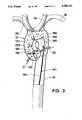
- FIG. 3is a partial perspective view of a heart, showing the aortic arch and major arteries, and showing an intravascular blood pump constructed according to the principles of the invention disposed within the aortic arch.
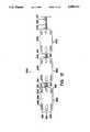
- FIG. 4is a partial perspective view of a first embodiment of an intravascular blood pump constructed according to the principles of the invention.
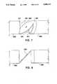
- FIG. 5is a plan view of a single-thread impeller.
- FIG. 6is a perspective view of a single-thread impeller.
- FIG. 7is a partial perspective view of an angular articulated link interconnecting two pump sections of the first embodiment.
- FIG. 8is a partial schematic side view of an angular articulated link interconnecting two pump sections of the first embodiment.
- FIGS. 9 and 10are partial schematic side views of a criss-cross articulated link interconnecting two pump sections of the first embodiment.
- FIG. 11is a partial schematic sectional view of a pump section and angular articulated link of the first embodiment.
- FIG. 12is a schematic side view of a second embodiment of an intravascular blood pump constructed according to the principles of the invention.
- FIG. 13is a schematic sectional view of a second embodiment of an intravascular blood pump constructed according to the principles of the invention revealing a multi-threaded impeller.
- FIG. 14is a partial perspective view of a third embodiment of an intravascular blood pump constructed according to the principles of the invention.
- FIG. 15is a front view of the articulation link of the third embodiment.
- FIG. 16is a partial view of a user body showing the external pump power source secured to the body by a support belt.
- the invention disclosed hereinoperates in aortic arch 13, as shown generally in FIG. 3.
- Multiple pump sections 150-190 interconnected with articulated links 200provide sufficient flexibility for pump 130 to navigate the aorta and iliofemoral arteries during installation, and ultimately fit within the confines of arch 13 during operation.
- the flexibility provided by the articulated linksneed only be off of a single plane (i.e., two directions located 180° apart) as the pump may be rotated during installation to provide maximum flexibility in the direction of the arterial bends.
- articulated links 200enable each pump section housing to be relatively positioned so to direct discharge flow 135 away from inlets of pump sections located further downstream and towards a variety of arterial inlets branching off the arch (i.e., the left subclavian artery 18, the left common carotid artery 19, the brachicocephalic artery 20, the coronary arteries 21 and 22, and the aorta itself 12).
- the effectiveness of such positioningmay be augmented by the angular orientation of the articulated link and/or the particular configuration of the pump section outlet, as discussed below.
- the housingsmay be secured to a stationary object relative to the rotational motion of cable 140.
- a stationary objectwill be teflon sleeve 141 which extends the full length of cable 140 and may be fixedly anchored to a stationary object outside the body.
- the orientation between each sectionalso remains fixed.
- proper orientationmay be maintained by resting one or more pump housing sections on the inner wall of the aortic arch and relying on friction to impede any rotational motion of each pump section housing during operation.
- an intravascular blood pump constructed according to the principles of the inventionincludes several fundamental elements.
- the articulated link interconnecting two pump sectionsshould be flexible off of at least one plane (i.e., flexible in two directions 180° apart) to enable an elongate assembly to navigate the iliofemoral and aorta arteries during installation and to effectively direct blood within the aortic arch during operation.
- each pump sectionshould be oriented to minimize the flow of blood from an upstream section outlet to a downstream section inlet.
- the outletsshould be configured to direct discharged blood towards arterial inlets located within the aortic arch.
- FIGS. 4-11A first, and preferred, embodiment of the invention is illustrated in FIGS. 4-11.
- the pump 230is shown with five pump sections 250, 260, 270, 280 and 290, and sleeve-stop 300.
- Pump section 250contains a plurality of inlets 310 and outlets 313 located on the sides of teflon, pump-section housing 370. These inlets and outlets are disposed near the front and midpoint, respectively, of the section.
- Outlets 313are designed to direct blood into the inlets of the coronary arteries, identified as elements 21 and 22 in FIG. 3.
- each of sections 260-290have a single inlet 312 and outlet 311 disposed at the ends of each teflon housing 350.
- Outlets 311direct blood into and through the portions of aortic arch 13 downstream of the coronary arteries.
- Sections 250 and 260are interconnected by means of criss-cross link 320, shown in detail in FIGS. 9 and 10.
- This linkprovides limited flexibility and no guidance to blood discharged from section 250 since the corresponding outlets are disposed on the side of the pump section housing.
- link 320is integrally formed with two pump section mounting portions 321 and 322.
- Portion 321provides a solid, short male insert (approximately 1/6th the length of housing 370) which rests inside housing 370 and is secured to the inner walls of the housing by a suitable adhesive, or other means.
- This insertcontains a passage large enough for cable 140 to pass through.
- Portion 322provides a hollow, cylindrical insert which extends the length of housing 350 and is secured to the inner walls of the housing by a suitable adhesive, or other means. This insert forms a double wall with housing 350 that is sufficiently wide to accommodate impeller 340.
- Remaining sections 260-290 and stop 300are interconnected by means of angular link 330, which has greater flexibility than link 320 and guides blood entering and exiting each section.
- each link 330creates a barrier between blood entering the inlet 312 of the downstream pump section and blood exiting the outlet 311 of the upstream pump section. Exiting blood 135 is directed away from entering blood 134, enabling the multiple pump sections to operate in parallel on different portions of a single blood stream exiting the heart.
- link 330When properly installed within aortic arch 13, link 330 is disposed so that discharge flow 135 is directed towards the aortic arch cavity downstream of the coronary artery. Accordingly, this link in combination with the relative position of each section within the arch provides a directed discharge flow away from the inlets of downstream pump sections and towards the various arterial inlets branching from the aortic arch, as shown generally in FIG. 3.
- link 330is integrally formed with housing 350 at exit 312 and pump section mounting portion 331.
- portion 331provides a hollow, cylindrical insert which extends the length of housing 350 and is secured to the inner walls of the housing by a suitable adhesive, or other means. This insert forms a double wall with housing 350 that is sufficiently wide to accommodate impeller 340.
- Each pump sectioncontains a nylon, left-handed, single-thread impeller 340, shown in detail in FIG. 11.
- Impeller 340is secured to cable 140 by a suitable adhesive, such as cyanoacrylate glue 360, or other means. Blood is drawn into the inlets and discharged from the outlets of each section as a result of the rotation of this impeller.
- the pitch of impeller 340is tailored to the length of the section in which it resides so that thread crest 341 traverses the length of its corresponding pump section in one rotation.
- pump sections 250-290each measure 0.75 inches in length, the presence of side-mounted inlets 310 on section 250 shortens the enclosed pumping chamber of this section to 0.3125 inches. Accordingly, the pitch of impeller 340 for section 250 is 0.3125 inches while the pitch of the impellers for the remaining sections is 0.75 inches.
- each pump section (260-290) containing the hollow cylindrical insert of pump section mounting portion 331is approximately 0.255 inches.
- the outer diameter of each impeller 340 contained within the foregoing sectionsis approximately 0.252 inches. Accordingly, impeller 340 operates with a clearance of approximately 0.003 inches.
- flexible cable 140passes through interconnected pump sections 250-290 and collectively rotates separate impellers contained within each section.
- This cableis constructed from seven course strands of steel wound about a central axis. Each course strand comprises 7 fine strands of steel.
- the resulting assemblyhaving a diameter of approximately 1/32 of an inch, is typically identified as "aircraft stainless steel cable.”
- Relative segment position on cable 140is provided by links 320 and 330 which maintain a pre-determined distance between each segment and stop 300.
- the cable itselfis held within pump assembly 230 by the restricted mobility of the impellers to which the cable is glued.
- Teflon sleeve 141which encases cable 140 as it traverses the aorta and iliofemoral arteries, terminates at stop 300, as illustrated in FIG. 4.
- This sleeveserves as a means for isolating pump assembly 230 from the rotational movement of cable 140 by being secured to both stop 300 and an external object that is stationary relative to the rotation of cable 140, such as the housing of the drive motor.
- FIGS. 12 and 13A second embodiment of the invention is illustrated in FIGS. 12 and 13.
- the pump 430is shown with three pump sections 450, 460, and 470.
- Each pump sectioncontains a plurality of inlets 490 and outlets 500 on each teflon housing 530 to accommodate the flow of blood.
- the inlets and outletsare angled to avoid a straight path of blood from the output of an upstream pump to the input of a downstream pump (i.e., sections 450 and 460, respectively).
- These outletsmay also contribute to the direction of discharge flow 135 towards the arterial inlets of aortic arch 13 when the segments are disposed within the arch in a manner similar to that illustrated in FIG. 3.
- one pump sectionmay contain additional outlets to direct blood into the intakes of the coronary arteries, identified as elements 21 and 22 in FIGS. 1 and 3. Such outputs would be disposed perpendicularly to the longitudinal axis of the pump section like outlets 313 of segment 250 in the first embodiment.
- each sectionlies a nylon, multiple-thread impeller 480 fixedly secured to cable 140 by a suitable adhesive, such as cyanoacrylate glue 520, or other means. Blood is drawn into inlets 490 and discharged via outlets 500 from the rotation of this impeller. To reduce the possibility of rotational slippage, that portion of cable 140 upon which impeller 480 rests may be flattened, as shown in FIG. 14. Impeller 480 is designed to pump a maximum displacement of blood per revolution. Alternatively, a multiple bladed turbine may also be used.
- a flexible cable 140 encased within teflon sleeve 141interconnects the pump sections and collectively rotates separate impellers contained within each section.
- the cable itselfis held within pump assembly 430 by the restricted mobility of the impellers to which the cable is secured.
- Relative section position on cable 140is maintained by teflon sleeve 141 which has a larger diameter than the section hole(s) 510 through which the cable passes. Accordingly, the sleeve properly interspaces the sections as well as maintains their position at one end of the cable. Additionally, the sleeve serves as a means for isolating the pump section housings from the rotational movement of cable 140 by being fixedly secured to both these housings as well as an external object which is stationary relative to the rotation of cable 140.
- pump 630includes multiple pump sections interconnected by an articulated link.
- a typical section 650contains a teflon housing 720 with a single inlet 700 and a plurality of outlets 690. Although some discharge may escape through the cable hole located in the base of 720, the amount should be minimal since lock nut 680 and washer 670 rest on top of the hole.
- the outlets 690are angle for reasons noted above.
- pump 630employs a multiple-thread impeller 480 connected to cable 140 as described above.
- the cablemaintains its position within each section by means of lock nut 680 resting against the section base.
- Pump sectionsare interconnected by means of an articulated "snap-on" link 710 as illustrated in FIGS. 14 and 15. This joint snaps over ridge 651 of housing 720 and provides for limited flexibility in all directions from the longitudinal axis of the section.
- housing 720 of pump 630are not fixedly secured to a stationary object relative to the rotation of cable 140. Rather, one or more of these housings rest on an inner wall of the aortic arch during operation, relying on friction to impede any rotational motion of such housings. Those housings not in direct contact with the aortic wall may rely on friction present in the connection of link 710 to indirectly restrain any rotational motion.
- FIG. 3The proper orientation of an articulated heart pump is shown generally in FIG. 3.
- the angled links of the first embodiment or the angled outlets of the second and third embodiments in conjunction with the relative position of the pump sections in the aortic archprovide the necessary combination to direct the blood towards desired arterial inlets.
- pumping volumes of approximately 0.57 l/min out of section 250 into the coronary arteries, and approximately 5-6 l/min out of the combined outputs of sections 260-290 into the aortic archhave been achieved at impeller rotational speeds of approximately 12,000 to 15,000 rpm.
- impeller rotational speedsapproximately 12,000 to 15,000 rpm.
- the effectiveness of this pumping volumeis enhanced by the directed discharge flow of each pump section into the appropriate arterial inlet of the aortic arch.
- cable 140was found to kink when rotated in the direction of the twist of its strands, that is, the direction that tightens the cable. Accordingly, in a preferred operation, cable 140 should be rotated in the direction opposite to the twist of its strands, that is, the direction that loosens the cable. In such an operation, cable 140 is held together by teflon sleeve 141.
- pump section housings, and impellersmay be constructed from teflon and nylon, respectively. These materials are chosen for their compatibility with blood, resistance to corrosion by blood and low operating friction. Any other material with similar characteristics may also be employed in the construction of these components of the invention.
- the external power source used to drive cable 140may be motor 800 secured to the user by means of support belt 810.
- the intravascular blood pumpWhen used for the first time, the intravascular blood pump can be brought up to speed very slowly to avoid shock. Once in operation, the system can use the same instrumentation now available with certain catheters to transmit blood pressure, heart rate and rpm, thereby providing sufficient information for feedback control.
Landscapes
- Health & Medical Sciences (AREA)
- Engineering & Computer Science (AREA)
- Heart & Thoracic Surgery (AREA)
- Life Sciences & Earth Sciences (AREA)
- Mechanical Engineering (AREA)
- Anesthesiology (AREA)
- Biomedical Technology (AREA)
- Hematology (AREA)
- Cardiology (AREA)
- Animal Behavior & Ethology (AREA)
- General Health & Medical Sciences (AREA)
- Public Health (AREA)
- Veterinary Medicine (AREA)
- Medical Informatics (AREA)
- Vascular Medicine (AREA)
- External Artificial Organs (AREA)
Abstract
Description
Claims (7)
Priority Applications (6)
| Application Number | Priority Date | Filing Date | Title |
|---|---|---|---|
| US07/914,381US5300112A (en) | 1992-07-14 | 1992-07-14 | Articulated heart pump |
| EP93918368AEP0738162A1 (en) | 1992-07-14 | 1993-07-14 | Articulated heart pump and method of use |
| PCT/US1993/006981WO1994001148A1 (en) | 1992-07-14 | 1993-07-14 | Articulated heart pump and method of use |
| AU47845/93AAU4784593A (en) | 1992-07-14 | 1993-07-14 | Articulated heart pump and method of use |
| CA002140144ACA2140144A1 (en) | 1992-07-14 | 1993-07-14 | Articulated heart pump and method of use |
| US08/183,422US5405383A (en) | 1992-07-14 | 1994-01-19 | Articulated heart pump and method of use |
Applications Claiming Priority (1)
| Application Number | Priority Date | Filing Date | Title |
|---|---|---|---|
| US07/914,381US5300112A (en) | 1992-07-14 | 1992-07-14 | Articulated heart pump |
Related Child Applications (1)
| Application Number | Title | Priority Date | Filing Date |
|---|---|---|---|
| US08/183,422DivisionUS5405383A (en) | 1992-07-14 | 1994-01-19 | Articulated heart pump and method of use |
Publications (1)
| Publication Number | Publication Date |
|---|---|
| US5300112Atrue US5300112A (en) | 1994-04-05 |
Family
ID=25434283
Family Applications (2)
| Application Number | Title | Priority Date | Filing Date |
|---|---|---|---|
| US07/914,381Expired - Fee RelatedUS5300112A (en) | 1992-07-14 | 1992-07-14 | Articulated heart pump |
| US08/183,422Expired - Fee RelatedUS5405383A (en) | 1992-07-14 | 1994-01-19 | Articulated heart pump and method of use |
Family Applications After (1)
| Application Number | Title | Priority Date | Filing Date |
|---|---|---|---|
| US08/183,422Expired - Fee RelatedUS5405383A (en) | 1992-07-14 | 1994-01-19 | Articulated heart pump and method of use |
Country Status (5)
| Country | Link |
|---|---|
| US (2) | US5300112A (en) |
| EP (1) | EP0738162A1 (en) |
| AU (1) | AU4784593A (en) |
| CA (1) | CA2140144A1 (en) |
| WO (1) | WO1994001148A1 (en) |
Cited By (75)
| Publication number | Priority date | Publication date | Assignee | Title |
|---|---|---|---|---|
| US5405383A (en)* | 1992-07-14 | 1995-04-11 | Aai Corporation | Articulated heart pump and method of use |
| US5810836A (en)* | 1996-03-04 | 1998-09-22 | Myocardial Stents, Inc. | Device and method for trans myocardial revascularization (TMR) |
| US20060161095A1 (en)* | 1999-09-03 | 2006-07-20 | A-Med Systems, Inc. | Guidable intravascular blood pump and related methods |
| US20070231135A1 (en)* | 2006-03-31 | 2007-10-04 | Orqis Medical Corporation | Rotary Blood Pump |
| US20080089797A1 (en)* | 2003-09-18 | 2008-04-17 | Wampler Richard K | Rotary Blood Pump |
| US20090060743A1 (en)* | 2004-09-17 | 2009-03-05 | The Penn State Research Foundation | Expandable impeller pump |
| US20100016960A1 (en)* | 1997-10-09 | 2010-01-21 | Bolling Steven F | Implantable Heart Assist System And Method Of Applying Same |
| US20110004046A1 (en)* | 2009-07-01 | 2011-01-06 | The Penn State Research Foundation | Blood pump with expandable cannula |
| EP2314331A1 (en)* | 2009-10-23 | 2011-04-27 | ECP Entwicklungsgesellschaft mbH | Catheter pump arrangement and flexible shaft arrangement with a cable core |
| US8449443B2 (en) | 2008-10-06 | 2013-05-28 | Indiana University Research And Technology Corporation | Active or passive assistance in the circulatory system |
| US8485961B2 (en) | 2011-01-05 | 2013-07-16 | Thoratec Corporation | Impeller housing for percutaneous heart pump |
| US8591393B2 (en) | 2011-01-06 | 2013-11-26 | Thoratec Corporation | Catheter pump |
| US8597170B2 (en) | 2011-01-05 | 2013-12-03 | Thoratec Corporation | Catheter pump |
| US8690749B1 (en) | 2009-11-02 | 2014-04-08 | Anthony Nunez | Wireless compressible heart pump |
| US8721517B2 (en) | 2012-05-14 | 2014-05-13 | Thoratec Corporation | Impeller for catheter pump |
| US8821365B2 (en) | 2009-07-29 | 2014-09-02 | Thoratec Corporation | Rotation drive device and centrifugal pump apparatus using the same |
| US9067005B2 (en) | 2008-12-08 | 2015-06-30 | Thoratec Corporation | Centrifugal pump apparatus |
| US9089634B2 (en) | 2009-09-22 | 2015-07-28 | Ecp Entwicklungsgesellschaft Mbh | Fluid pump having at least one impeller blade and a support device |
| US9138518B2 (en) | 2011-01-06 | 2015-09-22 | Thoratec Corporation | Percutaneous heart pump |
| US9308302B2 (en) | 2013-03-15 | 2016-04-12 | Thoratec Corporation | Catheter pump assembly including a stator |
| US9327067B2 (en) | 2012-05-14 | 2016-05-03 | Thoratec Corporation | Impeller for catheter pump |
| US9328741B2 (en) | 2010-05-17 | 2016-05-03 | Ecp Entwicklungsgesellschaft Mbh | Pump arrangement |
| US9358329B2 (en) | 2012-07-03 | 2016-06-07 | Thoratec Corporation | Catheter pump |
| US9364593B2 (en) | 2004-09-17 | 2016-06-14 | The Penn State Research Foundation | Heart assist device with expandable impeller pump |
| US9381288B2 (en) | 2013-03-13 | 2016-07-05 | Thoratec Corporation | Fluid handling system |
| US9421311B2 (en) | 2012-07-03 | 2016-08-23 | Thoratec Corporation | Motor assembly for catheter pump |
| US9446179B2 (en) | 2012-05-14 | 2016-09-20 | Thoratec Corporation | Distal bearing support |
| US9556873B2 (en) | 2013-02-27 | 2017-01-31 | Tc1 Llc | Startup sequence for centrifugal pump with levitated impeller |
| US9623161B2 (en) | 2014-08-26 | 2017-04-18 | Tc1 Llc | Blood pump and method of suction detection |
| US9638202B2 (en) | 2010-09-14 | 2017-05-02 | Tc1 Llc | Centrifugal pump apparatus |
| US9675738B2 (en) | 2015-01-22 | 2017-06-13 | Tc1 Llc | Attachment mechanisms for motor of catheter pump |
| US9675739B2 (en) | 2015-01-22 | 2017-06-13 | Tc1 Llc | Motor assembly with heat exchanger for catheter pump |
| US9709061B2 (en) | 2013-01-24 | 2017-07-18 | Tc1 Llc | Impeller position compensation using field oriented control |
| US9770543B2 (en) | 2015-01-22 | 2017-09-26 | Tc1 Llc | Reduced rotational mass motor assembly for catheter pump |
| US9827356B2 (en) | 2014-04-15 | 2017-11-28 | Tc1 Llc | Catheter pump with access ports |
| US9850906B2 (en) | 2011-03-28 | 2017-12-26 | Tc1 Llc | Rotation drive device and centrifugal pump apparatus employing same |
| US9872947B2 (en) | 2012-05-14 | 2018-01-23 | Tc1 Llc | Sheath system for catheter pump |
| US9907890B2 (en) | 2015-04-16 | 2018-03-06 | Tc1 Llc | Catheter pump with positioning brace |
| WO2018089970A1 (en)* | 2016-11-14 | 2018-05-17 | Tc1 Llc | Sheath assembly for catheter pump |
| WO2018132182A1 (en)* | 2017-01-12 | 2018-07-19 | Desilva Peter | Ventricular assist device |
| US10029037B2 (en) | 2014-04-15 | 2018-07-24 | Tc1 Llc | Sensors for catheter pumps |
| US10052420B2 (en) | 2013-04-30 | 2018-08-21 | Tc1 Llc | Heart beat identification and pump speed synchronization |
| US10105475B2 (en) | 2014-04-15 | 2018-10-23 | Tc1 Llc | Catheter pump introducer systems and methods |
| US10117983B2 (en) | 2015-11-16 | 2018-11-06 | Tc1 Llc | Pressure/flow characteristic modification of a centrifugal pump in a ventricular assist device |
| US10166318B2 (en) | 2015-02-12 | 2019-01-01 | Tc1 Llc | System and method for controlling the position of a levitated rotor |
| US10245361B2 (en) | 2015-02-13 | 2019-04-02 | Tc1 Llc | Impeller suspension mechanism for heart pump |
| US10371152B2 (en) | 2015-02-12 | 2019-08-06 | Tc1 Llc | Alternating pump gaps |
| US10449279B2 (en) | 2014-08-18 | 2019-10-22 | Tc1 Llc | Guide features for percutaneous catheter pump |
| US10506935B2 (en) | 2015-02-11 | 2019-12-17 | Tc1 Llc | Heart beat identification and pump speed synchronization |
| US10525178B2 (en) | 2013-03-15 | 2020-01-07 | Tc1 Llc | Catheter pump assembly including a stator |
| US10583232B2 (en) | 2014-04-15 | 2020-03-10 | Tc1 Llc | Catheter pump with off-set motor position |
| US10722631B2 (en) | 2018-02-01 | 2020-07-28 | Shifamed Holdings, Llc | Intravascular blood pumps and methods of use and manufacture |
| US11033728B2 (en) | 2013-03-13 | 2021-06-15 | Tc1 Llc | Fluid handling system |
| US11077294B2 (en) | 2013-03-13 | 2021-08-03 | Tc1 Llc | Sheath assembly for catheter pump |
| US20210260361A1 (en)* | 2018-06-25 | 2021-08-26 | Modeus Inc. | Percutaneous blood pump and introducer system |
| US11160970B2 (en) | 2016-07-21 | 2021-11-02 | Tc1 Llc | Fluid seals for catheter pump motor assembly |
| US11185677B2 (en) | 2017-06-07 | 2021-11-30 | Shifamed Holdings, Llc | Intravascular fluid movement devices, systems, and methods of use |
| US11219756B2 (en) | 2012-07-03 | 2022-01-11 | Tc1 Llc | Motor assembly for catheter pump |
| US11229786B2 (en) | 2012-05-14 | 2022-01-25 | Tc1 Llc | Impeller for catheter pump |
| US11491322B2 (en) | 2016-07-21 | 2022-11-08 | Tc1 Llc | Gas-filled chamber for catheter pump motor assembly |
| US11511103B2 (en) | 2017-11-13 | 2022-11-29 | Shifamed Holdings, Llc | Intravascular fluid movement devices, systems, and methods of use |
| US11654275B2 (en) | 2019-07-22 | 2023-05-23 | Shifamed Holdings, Llc | Intravascular blood pumps with struts and methods of use and manufacture |
| CN116212227A (en)* | 2022-12-28 | 2023-06-06 | 苏州心擎医疗技术有限公司 | Ventricular assist catheter pump |
| US11724089B2 (en) | 2019-09-25 | 2023-08-15 | Shifamed Holdings, Llc | Intravascular blood pump systems and methods of use and control thereof |
| US20240017052A1 (en)* | 2004-08-13 | 2024-01-18 | Procyrion, Inc. | Method and apparatus for long-term assisting a left ventricle to pump blood |
| US11964145B2 (en) | 2019-07-12 | 2024-04-23 | Shifamed Holdings, Llc | Intravascular blood pumps and methods of manufacture and use |
| US12102815B2 (en) | 2019-09-25 | 2024-10-01 | Shifamed Holdings, Llc | Catheter blood pumps and collapsible pump housings |
| US12121713B2 (en) | 2019-09-25 | 2024-10-22 | Shifamed Holdings, Llc | Catheter blood pumps and collapsible blood conduits |
| US12128228B2 (en) | 2019-05-23 | 2024-10-29 | Magenta Medical Ltd | Blood pumps |
| US20240358994A1 (en)* | 2021-06-02 | 2024-10-31 | Inventure Tech Ltd | In-vivo micro blood pump |
| US12161857B2 (en) | 2018-07-31 | 2024-12-10 | Shifamed Holdings, Llc | Intravascular blood pumps and methods of use |
| US12220570B2 (en) | 2018-10-05 | 2025-02-11 | Shifamed Holdings, Llc | Intravascular blood pumps and methods of use |
| US12390631B2 (en)* | 2015-05-18 | 2025-08-19 | Magenta Medical Ltd. | Blood pump |
| US12409310B2 (en) | 2019-12-11 | 2025-09-09 | Shifamed Holdings, Llc | Descending aorta and vena cava blood pumps |
| US12414851B2 (en) | 2013-03-13 | 2025-09-16 | Magenta Medical Ltd | Impeller for blood pump |
Families Citing this family (75)
| Publication number | Priority date | Publication date | Assignee | Title |
|---|---|---|---|---|
| US6129704A (en) | 1997-06-12 | 2000-10-10 | Schneider (Usa) Inc. | Perfusion balloon catheter having a magnetically driven impeller |
| US6086527A (en)* | 1998-04-02 | 2000-07-11 | Scimed Life Systems, Inc. | System for treating congestive heart failure |
| DE10336902C5 (en) | 2003-08-08 | 2019-04-25 | Abiomed Europe Gmbh | Intracardiac pumping device |
| US9028392B2 (en)* | 2006-12-01 | 2015-05-12 | NuCardia, Inc. | Medical device |
| US7828710B2 (en)* | 2007-06-05 | 2010-11-09 | Medical Value Partners, Llc | Apparatus comprising a drive cable for a medical device |
| US8079948B2 (en)* | 2007-08-29 | 2011-12-20 | NuCardia, Inc. | Article comprising an impeller |
| US8439859B2 (en) | 2007-10-08 | 2013-05-14 | Ais Gmbh Aachen Innovative Solutions | Catheter device |
| US8489190B2 (en) | 2007-10-08 | 2013-07-16 | Ais Gmbh Aachen Innovative Solutions | Catheter device |
| EP2047873B1 (en) | 2007-10-08 | 2010-12-15 | Ais Gmbh Aachen Innovative Solutions | Catheter device |
| WO2009091965A1 (en)* | 2008-01-18 | 2009-07-23 | Med Institute, Inc. | Intravascular device attachment system having tubular expandable body |
| JP5171953B2 (en) | 2008-06-23 | 2013-03-27 | テルモ株式会社 | Blood pump device |
| EP2194278A1 (en) | 2008-12-05 | 2010-06-09 | ECP Entwicklungsgesellschaft mbH | Fluid pump with a rotor |
| EP2216059A1 (en) | 2009-02-04 | 2010-08-11 | ECP Entwicklungsgesellschaft mbH | Catheter device with a catheter and an actuation device |
| JP5378010B2 (en) | 2009-03-05 | 2013-12-25 | ソラテック コーポレーション | Centrifugal pump device |
| CN102341600B (en) | 2009-03-06 | 2014-12-10 | 胸腔科技有限公司 | Centrifugal pump device |
| EP2229965A1 (en) | 2009-03-18 | 2010-09-22 | ECP Entwicklungsgesellschaft mbH | Fluid pump with particular form of a rotor blade |
| EP2246078A1 (en) | 2009-04-29 | 2010-11-03 | ECP Entwicklungsgesellschaft mbH | Shaft assembly with a shaft which moves within a fluid-filled casing |
| EP2248544A1 (en) | 2009-05-05 | 2010-11-10 | ECP Entwicklungsgesellschaft mbH | Fluid pump with variable circumference, particularly for medical use |
| EP2266640A1 (en) | 2009-06-25 | 2010-12-29 | ECP Entwicklungsgesellschaft mbH | Compressible and expandable turbine blade for a fluid pump |
| EP2282070B1 (en) | 2009-08-06 | 2012-10-17 | ECP Entwicklungsgesellschaft mbH | Catheter device with a coupling device for a drive device |
| EP2299119B1 (en) | 2009-09-22 | 2018-11-07 | ECP Entwicklungsgesellschaft mbH | Inflatable rotor for a fluid pump |
| EP2298371A1 (en) | 2009-09-22 | 2011-03-23 | ECP Entwicklungsgesellschaft mbH | Function element, in particular fluid pump with a housing and a transport element |
| EP2298372A1 (en) | 2009-09-22 | 2011-03-23 | ECP Entwicklungsgesellschaft mbH | Rotor for an axial pump for transporting a fluid |
| EP2314330A1 (en) | 2009-10-23 | 2011-04-27 | ECP Entwicklungsgesellschaft mbH | Flexible shaft arrangement |
| EP2338539A1 (en) | 2009-12-23 | 2011-06-29 | ECP Entwicklungsgesellschaft mbH | Pump device with a detection device |
| EP2338540A1 (en) | 2009-12-23 | 2011-06-29 | ECP Entwicklungsgesellschaft mbH | Delivery blade for a compressible rotor |
| EP2338541A1 (en) | 2009-12-23 | 2011-06-29 | ECP Entwicklungsgesellschaft mbH | Radial compressible and expandable rotor for a fluid pump |
| EP2347778A1 (en) | 2010-01-25 | 2011-07-27 | ECP Entwicklungsgesellschaft mbH | Fluid pump with a radially compressible rotor |
| JP5443197B2 (en) | 2010-02-16 | 2014-03-19 | ソラテック コーポレーション | Centrifugal pump device |
| EP2363157A1 (en) | 2010-03-05 | 2011-09-07 | ECP Entwicklungsgesellschaft mbH | Device for exerting mechanical force on a medium, in particular fluid pump |
| JP5572832B2 (en) | 2010-03-26 | 2014-08-20 | ソーラテック コーポレイション | Centrifugal blood pump device |
| EP2399639A1 (en) | 2010-06-25 | 2011-12-28 | ECP Entwicklungsgesellschaft mbH | System for introducing a pump |
| JP5681403B2 (en) | 2010-07-12 | 2015-03-11 | ソーラテック コーポレイション | Centrifugal pump device |
| EP2407187A3 (en) | 2010-07-15 | 2012-06-20 | ECP Entwicklungsgesellschaft mbH | Blood pump for invasive application within the body of a patient |
| EP2407186A1 (en) | 2010-07-15 | 2012-01-18 | ECP Entwicklungsgesellschaft mbH | Rotor for a pump, produced with an initial elastic material |
| EP2407185A1 (en) | 2010-07-15 | 2012-01-18 | ECP Entwicklungsgesellschaft mbH | Radial compressible and expandable rotor for a pump with a turbine blade |
| EP2422735A1 (en) | 2010-08-27 | 2012-02-29 | ECP Entwicklungsgesellschaft mbH | Implantable blood transportation device, manipulation device and coupling device |
| US9155612B2 (en) | 2011-01-10 | 2015-10-13 | Intermountain Invention Management, Llc | Composite stent grafts for in situ assembly and related methods |
| EP2497521A1 (en) | 2011-03-10 | 2012-09-12 | ECP Entwicklungsgesellschaft mbH | Push device for axial insertion of a string-shaped, flexible body |
| EP2564771A1 (en) | 2011-09-05 | 2013-03-06 | ECP Entwicklungsgesellschaft mbH | Medicinal product with a functional element for invasive use in the body of a patient |
| US8926492B2 (en) | 2011-10-11 | 2015-01-06 | Ecp Entwicklungsgesellschaft Mbh | Housing for a functional element |
| EP2606919A1 (en) | 2011-12-22 | 2013-06-26 | ECP Entwicklungsgesellschaft mbH | Sluice device for inserting a catheter |
| EP2606920A1 (en) | 2011-12-22 | 2013-06-26 | ECP Entwicklungsgesellschaft mbH | Sluice device for inserting a catheter |
| JP6083929B2 (en) | 2012-01-18 | 2017-02-22 | ソーラテック コーポレイション | Centrifugal pump device |
| EP2830675B1 (en) | 2012-03-26 | 2025-06-25 | Procyrion, Inc. | Systems and methods for fluid flows and/or pressures for circulation and perfusion enhancement |
| CN108742951B (en) | 2012-06-06 | 2021-05-25 | 洋红医疗有限公司 | Artificial kidney valve |
| EP2745869A1 (en) | 2012-12-21 | 2014-06-25 | ECP Entwicklungsgesellschaft mbH | Sluice assembly for the introduction of a cord-like body, in particular of a catheter, into a patient |
| US10583231B2 (en) | 2013-03-13 | 2020-03-10 | Magenta Medical Ltd. | Blood pump |
| US9713663B2 (en) | 2013-04-30 | 2017-07-25 | Tc1 Llc | Cardiac pump with speed adapted for ventricle unloading |
| US9314559B2 (en)* | 2013-08-30 | 2016-04-19 | Steve Smith | Four chamber redundant-impeller artificial heart |
| US9764113B2 (en) | 2013-12-11 | 2017-09-19 | Magenta Medical Ltd | Curved catheter |
| EP4290081A3 (en) | 2015-09-25 | 2024-02-21 | Procyrion, Inc. | Non-occluding intravascular blood pump providing reduced hemolysis |
| EP3518825B1 (en) | 2016-09-29 | 2020-05-27 | Magenta Medical Ltd. | Blood vessel tube |
| CA3039285A1 (en) | 2016-10-25 | 2018-05-03 | Magenta Medical Ltd. | Ventricular assist device |
| JP7094279B2 (en) | 2016-11-23 | 2022-07-01 | マジェンタ・メディカル・リミテッド | Blood pump |
| US10905808B2 (en) | 2018-01-10 | 2021-02-02 | Magenta Medical Ltd. | Drive cable for use with a blood pump |
| EP3638336B1 (en) | 2018-01-10 | 2022-04-06 | Magenta Medical Ltd. | Ventricular assist device |
| DE102018201030B4 (en) | 2018-01-24 | 2025-10-16 | Kardion Gmbh | Magnetic dome element with magnetic bearing function |
| US10893927B2 (en) | 2018-03-29 | 2021-01-19 | Magenta Medical Ltd. | Inferior vena cava blood-flow implant |
| DE102018207575A1 (en) | 2018-05-16 | 2019-11-21 | Kardion Gmbh | Magnetic face turning coupling for the transmission of torques |
| DE102018207611A1 (en) | 2018-05-16 | 2019-11-21 | Kardion Gmbh | Rotor bearing system |
| DE102018208541A1 (en) | 2018-05-30 | 2019-12-05 | Kardion Gmbh | Axial pump for a cardiac assist system and method of making an axial pump for a cardiac assist system |
| DE102018208539A1 (en) | 2018-05-30 | 2019-12-05 | Kardion Gmbh | A motor housing module for sealing an engine compartment of a motor of a cardiac assist system and cardiac assistance system and method for mounting a cardiac assist system |
| DE102018208550A1 (en) | 2018-05-30 | 2019-12-05 | Kardion Gmbh | A lead device for directing blood flow to a cardiac assist system, cardiac assist system, and method of making a lead device |
| DE102018208538A1 (en) | 2018-05-30 | 2019-12-05 | Kardion Gmbh | Intravascular blood pump and process for the production of electrical conductors |
| DE102018210076A1 (en) | 2018-06-21 | 2019-12-24 | Kardion Gmbh | Method and device for detecting a state of wear of a cardiac support system, method and device for operating a cardiac support system and cardiac support system |
| DE102018210058A1 (en) | 2018-06-21 | 2019-12-24 | Kardion Gmbh | Stator blade device for guiding the flow of a fluid flowing out of an outlet opening of a heart support system, heart support system with stator blade device, method for operating a stator blade device and manufacturing method |
| DE102018211327A1 (en) | 2018-07-10 | 2020-01-16 | Kardion Gmbh | Impeller for an implantable vascular support system |
| DE102018212153A1 (en) | 2018-07-20 | 2020-01-23 | Kardion Gmbh | Inlet line for a pump unit of a cardiac support system, cardiac support system and method for producing an inlet line for a pump unit of a cardiac support system |
| CN112654389A (en) | 2018-08-07 | 2021-04-13 | 开迪恩有限公司 | Bearing device for a cardiac support system and method for flushing an intermediate space in a bearing device for a cardiac support system |
| AU2020211431B2 (en) | 2019-01-24 | 2024-10-24 | Magenta Medical Ltd | Ventricular assist device |
| IL293625A (en) | 2019-12-03 | 2022-08-01 | Procyrion Inc | blood pumps |
| WO2021119413A1 (en) | 2019-12-13 | 2021-06-17 | Procyrion, Inc. | Support structures for intravascular blood pumps |
| DE102020102474A1 (en) | 2020-01-31 | 2021-08-05 | Kardion Gmbh | Pump for conveying a fluid and method for manufacturing a pump |
| EP3984589B1 (en) | 2020-04-07 | 2023-08-23 | Magenta Medical Ltd. | Magnetic phase sensing |
Citations (15)
| Publication number | Priority date | Publication date | Assignee | Title |
|---|---|---|---|---|
| US3203352A (en)* | 1962-05-24 | 1965-08-31 | Schafranek Gustav | Multiple pump assembly |
| US4625712A (en)* | 1983-09-28 | 1986-12-02 | Nimbus, Inc. | High-capacity intravascular blood pump utilizing percutaneous access |
| US4704121A (en)* | 1983-09-28 | 1987-11-03 | Nimbus, Inc. | Anti-thrombogenic blood pump |
| US4817586A (en)* | 1987-11-24 | 1989-04-04 | Nimbus Medical, Inc. | Percutaneous bloom pump with mixed-flow output |
| US4846152A (en)* | 1987-11-24 | 1989-07-11 | Nimbus Medical, Inc. | Single-stage axial flow blood pump |
| US4895557A (en)* | 1987-12-07 | 1990-01-23 | Nimbus Medical, Inc. | Drive mechanism for powering intravascular blood pumps |
| US4901413A (en)* | 1988-11-22 | 1990-02-20 | Shell Western E & P Inc. | Method and apparatus for establishing multi-stage gas separation upstream of a submersible pump |
| US4908012A (en)* | 1988-08-08 | 1990-03-13 | Nimbus Medical, Inc. | Chronic ventricular assist system |
| US4944722A (en)* | 1989-02-23 | 1990-07-31 | Nimbus Medical, Inc. | Percutaneous axial flow blood pump |
| US4957504A (en)* | 1988-12-02 | 1990-09-18 | Chardack William M | Implantable blood pump |
| US4964864A (en)* | 1988-09-27 | 1990-10-23 | American Biomed, Inc. | Heart assist pump |
| US4969865A (en)* | 1989-01-09 | 1990-11-13 | American Biomed, Inc. | Helifoil pump |
| US5040944A (en)* | 1989-09-11 | 1991-08-20 | Cook Einar P | Pump having impeller rotational about convoluted stationary member |
| US5049134A (en)* | 1989-05-08 | 1991-09-17 | The Cleveland Clinic Foundation | Sealless heart pump |
| US5092844A (en)* | 1990-04-10 | 1992-03-03 | Mayo Foundation For Medical Education And Research | Intracatheter perfusion pump apparatus and method |
Family Cites Families (1)
| Publication number | Priority date | Publication date | Assignee | Title |
|---|---|---|---|---|
| US5300112A (en)* | 1992-07-14 | 1994-04-05 | Aai Corporation | Articulated heart pump |
- 1992
- 1992-07-14USUS07/914,381patent/US5300112A/ennot_activeExpired - Fee Related
- 1993
- 1993-07-14AUAU47845/93Apatent/AU4784593A/ennot_activeAbandoned
- 1993-07-14WOPCT/US1993/006981patent/WO1994001148A1/ennot_activeApplication Discontinuation
- 1993-07-14EPEP93918368Apatent/EP0738162A1/ennot_activeWithdrawn
- 1993-07-14CACA002140144Apatent/CA2140144A1/ennot_activeAbandoned
- 1994
- 1994-01-19USUS08/183,422patent/US5405383A/ennot_activeExpired - Fee Related
Patent Citations (15)
| Publication number | Priority date | Publication date | Assignee | Title |
|---|---|---|---|---|
| US3203352A (en)* | 1962-05-24 | 1965-08-31 | Schafranek Gustav | Multiple pump assembly |
| US4625712A (en)* | 1983-09-28 | 1986-12-02 | Nimbus, Inc. | High-capacity intravascular blood pump utilizing percutaneous access |
| US4704121A (en)* | 1983-09-28 | 1987-11-03 | Nimbus, Inc. | Anti-thrombogenic blood pump |
| US4817586A (en)* | 1987-11-24 | 1989-04-04 | Nimbus Medical, Inc. | Percutaneous bloom pump with mixed-flow output |
| US4846152A (en)* | 1987-11-24 | 1989-07-11 | Nimbus Medical, Inc. | Single-stage axial flow blood pump |
| US4895557A (en)* | 1987-12-07 | 1990-01-23 | Nimbus Medical, Inc. | Drive mechanism for powering intravascular blood pumps |
| US4908012A (en)* | 1988-08-08 | 1990-03-13 | Nimbus Medical, Inc. | Chronic ventricular assist system |
| US4964864A (en)* | 1988-09-27 | 1990-10-23 | American Biomed, Inc. | Heart assist pump |
| US4901413A (en)* | 1988-11-22 | 1990-02-20 | Shell Western E & P Inc. | Method and apparatus for establishing multi-stage gas separation upstream of a submersible pump |
| US4957504A (en)* | 1988-12-02 | 1990-09-18 | Chardack William M | Implantable blood pump |
| US4969865A (en)* | 1989-01-09 | 1990-11-13 | American Biomed, Inc. | Helifoil pump |
| US4944722A (en)* | 1989-02-23 | 1990-07-31 | Nimbus Medical, Inc. | Percutaneous axial flow blood pump |
| US5049134A (en)* | 1989-05-08 | 1991-09-17 | The Cleveland Clinic Foundation | Sealless heart pump |
| US5040944A (en)* | 1989-09-11 | 1991-08-20 | Cook Einar P | Pump having impeller rotational about convoluted stationary member |
| US5092844A (en)* | 1990-04-10 | 1992-03-03 | Mayo Foundation For Medical Education And Research | Intracatheter perfusion pump apparatus and method |
Cited By (193)
| Publication number | Priority date | Publication date | Assignee | Title |
|---|---|---|---|---|
| US5405383A (en)* | 1992-07-14 | 1995-04-11 | Aai Corporation | Articulated heart pump and method of use |
| US5810836A (en)* | 1996-03-04 | 1998-09-22 | Myocardial Stents, Inc. | Device and method for trans myocardial revascularization (TMR) |
| US20100016960A1 (en)* | 1997-10-09 | 2010-01-21 | Bolling Steven F | Implantable Heart Assist System And Method Of Applying Same |
| US7998054B2 (en) | 1997-10-09 | 2011-08-16 | Thoratec Corporation | Implantable heart assist system and method of applying same |
| US10238783B2 (en) | 1999-09-03 | 2019-03-26 | Maquet Cardiovascular Llc | Guidable intravascular blood pump and related methods |
| US10357598B2 (en) | 1999-09-03 | 2019-07-23 | Maquet Cardiovascular Llc | Guidable intravascular blood pump and related methods |
| US9545468B2 (en) | 1999-09-03 | 2017-01-17 | Maquet Cardiovascular Llc | Guidable intravascular blood pump and related methods |
| US10328191B2 (en) | 1999-09-03 | 2019-06-25 | Maquet Cardiovascular Llc | Guidable intravascular blood pump and related methods |
| US10322218B2 (en) | 1999-09-03 | 2019-06-18 | Maquet Cardiovascular Llc | Guidable intravascular blood pump and related methods |
| US7731675B2 (en)* | 1999-09-03 | 2010-06-08 | Maquet Cardiovascular Llc | Guidable intravascular blood pump and related methods |
| US20100210895A1 (en)* | 1999-09-03 | 2010-08-19 | Aboul-Hosn Walid N | Guidable Intravascular Blood Pump and Related Methods |
| US9597437B2 (en) | 1999-09-03 | 2017-03-21 | Maquet Cardiovascular Llc | Guidable intravascular blood pump and related methods |
| US9789238B2 (en) | 1999-09-03 | 2017-10-17 | Maquet Cardiovascular, Llc | Guidable intravascular blood pump and related methods |
| US9327068B2 (en) | 1999-09-03 | 2016-05-03 | Maquet Cardiovascular Llc | Guidable intravascular blood pump and related methods |
| US9561314B2 (en) | 1999-09-03 | 2017-02-07 | Maquet Cardiovascular Llc | Guidable intravascular blood pump and related methods |
| US20060161095A1 (en)* | 1999-09-03 | 2006-07-20 | A-Med Systems, Inc. | Guidable intravascular blood pump and related methods |
| US10279095B2 (en) | 1999-09-03 | 2019-05-07 | Maquet Cardiovascular Llc | Guidable intravascular blood pump and related methods |
| US10300186B2 (en) | 1999-09-03 | 2019-05-28 | Maquet Cardiovascular Llc | Guidable intravascular blood pump and related methods |
| US10300185B2 (en) | 1999-09-03 | 2019-05-28 | Maquet Cardiovascular Llc | Guidable intravascular blood pump and related methods |
| US8888728B2 (en) | 1999-09-03 | 2014-11-18 | Maquet Cardiovascular Llc | Guidable intravascular blood pump and related methods |
| US8118724B2 (en) | 2003-09-18 | 2012-02-21 | Thoratec Corporation | Rotary blood pump |
| US20080095648A1 (en)* | 2003-09-18 | 2008-04-24 | Wampler Richard K | Rotary Blood Pump |
| US20100135832A1 (en)* | 2003-09-18 | 2010-06-03 | Wampler Richard K | Rotary Blood Pump |
| US20080089797A1 (en)* | 2003-09-18 | 2008-04-17 | Wampler Richard K | Rotary Blood Pump |
| US8684902B2 (en) | 2003-09-18 | 2014-04-01 | Thoratec Corporation | Rotary blood pump |
| US20240017052A1 (en)* | 2004-08-13 | 2024-01-18 | Procyrion, Inc. | Method and apparatus for long-term assisting a left ventricle to pump blood |
| US11428236B2 (en) | 2004-09-17 | 2022-08-30 | Tc1 Llc | Expandable impeller pump |
| US9364592B2 (en) | 2004-09-17 | 2016-06-14 | The Penn State Research Foundation | Heart assist device with expandable impeller pump |
| US20090060743A1 (en)* | 2004-09-17 | 2009-03-05 | The Penn State Research Foundation | Expandable impeller pump |
| US9717833B2 (en) | 2004-09-17 | 2017-08-01 | The Penn State Research Foundation | Heart assist device with expandable impeller pump |
| US8376707B2 (en) | 2004-09-17 | 2013-02-19 | Thoratec Corporation | Expandable impeller pump |
| US8992163B2 (en) | 2004-09-17 | 2015-03-31 | Thoratec Corporation | Expandable impeller pump |
| US9364593B2 (en) | 2004-09-17 | 2016-06-14 | The Penn State Research Foundation | Heart assist device with expandable impeller pump |
| US11434921B2 (en) | 2004-09-17 | 2022-09-06 | Tc1 Llc | Expandable impeller pump |
| US20110236210A1 (en)* | 2004-09-17 | 2011-09-29 | The Penn State Research Foundation | Expandable impeller pump |
| US7927068B2 (en) | 2004-09-17 | 2011-04-19 | Thoratec Corporation | Expandable impeller pump |
| US10215187B2 (en) | 2004-09-17 | 2019-02-26 | Tc1 Llc | Expandable impeller pump |
| US11708833B2 (en) | 2006-03-23 | 2023-07-25 | The Penn State Research Foundation | Heart assist device with expandable impeller pump |
| US10864309B2 (en) | 2006-03-23 | 2020-12-15 | The Penn State Research Foundation | Heart assist device with expandable impeller pump |
| US10149932B2 (en) | 2006-03-23 | 2018-12-11 | The Penn State Research Foundation | Heart assist device with expandable impeller pump |
| US12404858B2 (en) | 2006-03-23 | 2025-09-02 | The Penn State Research Foundation | Catheter blood pump heart assist device |
| US20070231135A1 (en)* | 2006-03-31 | 2007-10-04 | Orqis Medical Corporation | Rotary Blood Pump |
| US9512852B2 (en) | 2006-03-31 | 2016-12-06 | Thoratec Corporation | Rotary blood pump |
| US8449443B2 (en) | 2008-10-06 | 2013-05-28 | Indiana University Research And Technology Corporation | Active or passive assistance in the circulatory system |
| US9067005B2 (en) | 2008-12-08 | 2015-06-30 | Thoratec Corporation | Centrifugal pump apparatus |
| US8684904B2 (en) | 2009-07-01 | 2014-04-01 | Thoratec Corporation | Blood pump with expandable cannula |
| US20110004046A1 (en)* | 2009-07-01 | 2011-01-06 | The Penn State Research Foundation | Blood pump with expandable cannula |
| US8535211B2 (en) | 2009-07-01 | 2013-09-17 | Thoratec Corporation | Blood pump with expandable cannula |
| US8821365B2 (en) | 2009-07-29 | 2014-09-02 | Thoratec Corporation | Rotation drive device and centrifugal pump apparatus using the same |
| US11592028B2 (en) | 2009-09-22 | 2023-02-28 | Ecp Entwicklungsgesellschaft Mbh | Fluid pump having at least one impeller blade and a support device |
| US10208763B2 (en) | 2009-09-22 | 2019-02-19 | Ecp Entwicklungsgesellschaft Mbh | Fluid pump having at least one impeller blade and a support device |
| US12066030B2 (en)* | 2009-09-22 | 2024-08-20 | Ecp Entwicklungsgesellschaft Mbh | Fluid pump having at least one impeller blade and a support device |
| US9089634B2 (en) | 2009-09-22 | 2015-07-28 | Ecp Entwicklungsgesellschaft Mbh | Fluid pump having at least one impeller blade and a support device |
| CN102711861B (en)* | 2009-10-23 | 2015-08-19 | Ecp发展有限责任公司 | Catheter pump structure and there is the flexible axis structure of core |
| WO2011047884A1 (en)* | 2009-10-23 | 2011-04-28 | Ecp Entwicklungsgesellschaft Mbh | Catheter pump arrangement and flexible shaft arrangement having a core |
| CN102711861A (en)* | 2009-10-23 | 2012-10-03 | Ecp发展有限责任公司 | Catheter pump arrangement and flexible shaft arrangement having a core |
| EP2314331A1 (en)* | 2009-10-23 | 2011-04-27 | ECP Entwicklungsgesellschaft mbH | Catheter pump arrangement and flexible shaft arrangement with a cable core |
| US9603983B2 (en) | 2009-10-23 | 2017-03-28 | Ecp Entwicklungsgesellschaft Mbh | Catheter pump arrangement and flexible shaft arrangement having a core |
| US10792406B2 (en) | 2009-10-23 | 2020-10-06 | Ecp Entwicklungsgesellschaft Mbh | Catheter pump arrangement and flexible shaft arrangement having a core |
| US12313113B2 (en) | 2009-10-23 | 2025-05-27 | Ecp Entwicklungsgesellschaft Mbh | Catheter pump arrangement and flexible shaft arrangement having a core |
| US8690749B1 (en) | 2009-11-02 | 2014-04-08 | Anthony Nunez | Wireless compressible heart pump |
| US9759237B2 (en) | 2010-05-17 | 2017-09-12 | Ecp Entwicklungsgesellschaft Mbh | Pump arrangement |
| US11168705B2 (en) | 2010-05-17 | 2021-11-09 | Ecp Entwicklungsgesellschaft Mbh | Pump arrangement |
| US9328741B2 (en) | 2010-05-17 | 2016-05-03 | Ecp Entwicklungsgesellschaft Mbh | Pump arrangement |
| US10221866B2 (en) | 2010-05-17 | 2019-03-05 | Ecp Entwicklungsgesellschaft Mbh | Pump arrangement |
| US11976674B2 (en) | 2010-05-17 | 2024-05-07 | Ecp Entwicklungsgesellschaft Mbh | Pump arrangement |
| US9638202B2 (en) | 2010-09-14 | 2017-05-02 | Tc1 Llc | Centrifugal pump apparatus |
| US8597170B2 (en) | 2011-01-05 | 2013-12-03 | Thoratec Corporation | Catheter pump |
| US8485961B2 (en) | 2011-01-05 | 2013-07-16 | Thoratec Corporation | Impeller housing for percutaneous heart pump |
| US9138518B2 (en) | 2011-01-06 | 2015-09-22 | Thoratec Corporation | Percutaneous heart pump |
| US9962475B2 (en) | 2011-01-06 | 2018-05-08 | Tc1 Llc | Percutaneous heart pump |
| US8591393B2 (en) | 2011-01-06 | 2013-11-26 | Thoratec Corporation | Catheter pump |
| US10960116B2 (en) | 2011-01-06 | 2021-03-30 | Tci Llc | Percutaneous heart pump |
| US9850906B2 (en) | 2011-03-28 | 2017-12-26 | Tc1 Llc | Rotation drive device and centrifugal pump apparatus employing same |
| US11964144B2 (en) | 2012-05-14 | 2024-04-23 | Tc1 Llc | Sheath system for catheter pump |
| US8721517B2 (en) | 2012-05-14 | 2014-05-13 | Thoratec Corporation | Impeller for catheter pump |
| US10117980B2 (en) | 2012-05-14 | 2018-11-06 | Tc1 Llc | Distal bearing support |
| US10765789B2 (en) | 2012-05-14 | 2020-09-08 | Tc1 Llc | Impeller for catheter pump |
| US9446179B2 (en) | 2012-05-14 | 2016-09-20 | Thoratec Corporation | Distal bearing support |
| US9675740B2 (en) | 2012-05-14 | 2017-06-13 | Tc1 Llc | Impeller for catheter pump |
| US11045638B2 (en) | 2012-05-14 | 2021-06-29 | Tc1 Llc | Sheath system for catheter pump |
| US9327067B2 (en) | 2012-05-14 | 2016-05-03 | Thoratec Corporation | Impeller for catheter pump |
| US11357967B2 (en) | 2012-05-14 | 2022-06-14 | Tc1 Llc | Impeller for catheter pump |
| US11229786B2 (en) | 2012-05-14 | 2022-01-25 | Tc1 Llc | Impeller for catheter pump |
| US11311712B2 (en) | 2012-05-14 | 2022-04-26 | Tc1 Llc | Impeller for catheter pump |
| US9872947B2 (en) | 2012-05-14 | 2018-01-23 | Tc1 Llc | Sheath system for catheter pump |
| US10039872B2 (en) | 2012-05-14 | 2018-08-07 | Tc1 Llc | Impeller for catheter pump |
| US11260213B2 (en) | 2012-05-14 | 2022-03-01 | Tc1 Llc | Impeller for catheter pump |
| US9358329B2 (en) | 2012-07-03 | 2016-06-07 | Thoratec Corporation | Catheter pump |
| US11660441B2 (en) | 2012-07-03 | 2023-05-30 | Tc1 Llc | Catheter pump |
| US11219756B2 (en) | 2012-07-03 | 2022-01-11 | Tc1 Llc | Motor assembly for catheter pump |
| US12102813B2 (en) | 2012-07-03 | 2024-10-01 | Tc1 Llc | Motor assembly for catheter pump |
| US11833342B2 (en) | 2012-07-03 | 2023-12-05 | Tc1 Llc | Motor assembly for catheter pump |
| US11058865B2 (en) | 2012-07-03 | 2021-07-13 | Tc1 Llc | Catheter pump |
| US11944801B2 (en) | 2012-07-03 | 2024-04-02 | Tc1 Llc | Motor assembly for catheter pump |
| US11925797B2 (en) | 2012-07-03 | 2024-03-12 | Tc1 Llc | Motor assembly for catheter pump |
| US10576193B2 (en) | 2012-07-03 | 2020-03-03 | Tc1 Llc | Motor assembly for catheter pump |
| US11944802B2 (en) | 2012-07-03 | 2024-04-02 | Tc1 Llc | Motor assembly for catheter pump |
| US10086121B2 (en) | 2012-07-03 | 2018-10-02 | Tc1 Llc | Catheter pump |
| US11654276B2 (en) | 2012-07-03 | 2023-05-23 | Tc1 Llc | Catheter pump |
| US11925796B2 (en) | 2012-07-03 | 2024-03-12 | Tc1 Llc | Motor assembly for catheter pump |
| US9421311B2 (en) | 2012-07-03 | 2016-08-23 | Thoratec Corporation | Motor assembly for catheter pump |
| US12337165B2 (en) | 2012-07-03 | 2025-06-24 | Tc1 Llc | Catheter pump |
| US9709061B2 (en) | 2013-01-24 | 2017-07-18 | Tc1 Llc | Impeller position compensation using field oriented control |
| US9556873B2 (en) | 2013-02-27 | 2017-01-31 | Tc1 Llc | Startup sequence for centrifugal pump with levitated impeller |
| US12414851B2 (en) | 2013-03-13 | 2025-09-16 | Magenta Medical Ltd | Impeller for blood pump |
| US11547845B2 (en) | 2013-03-13 | 2023-01-10 | Tc1 Llc | Fluid handling system |
| US10632241B2 (en) | 2013-03-13 | 2020-04-28 | Tc1 Llc | Fluid handling system |
| US11850414B2 (en) | 2013-03-13 | 2023-12-26 | Tc1 Llc | Fluid handling system |
| US9381288B2 (en) | 2013-03-13 | 2016-07-05 | Thoratec Corporation | Fluid handling system |
| US11033728B2 (en) | 2013-03-13 | 2021-06-15 | Tc1 Llc | Fluid handling system |
| US11964119B2 (en) | 2013-03-13 | 2024-04-23 | Tc1 Llc | Sheath assembly for catheter pump |
| US11077294B2 (en) | 2013-03-13 | 2021-08-03 | Tc1 Llc | Sheath assembly for catheter pump |
| US10786610B2 (en) | 2013-03-15 | 2020-09-29 | Tc1 Llc | Catheter pump assembly including a stator |
| US10525178B2 (en) | 2013-03-15 | 2020-01-07 | Tc1 Llc | Catheter pump assembly including a stator |
| US9308302B2 (en) | 2013-03-15 | 2016-04-12 | Thoratec Corporation | Catheter pump assembly including a stator |
| US10071192B2 (en) | 2013-03-15 | 2018-09-11 | Tc1 Llp | Catheter pump assembly including a stator |
| US10052420B2 (en) | 2013-04-30 | 2018-08-21 | Tc1 Llc | Heart beat identification and pump speed synchronization |
| US10576192B2 (en) | 2014-04-15 | 2020-03-03 | Tc1 Llc | Catheter pump with access ports |
| US10029037B2 (en) | 2014-04-15 | 2018-07-24 | Tc1 Llc | Sensors for catheter pumps |
| US11173297B2 (en) | 2014-04-15 | 2021-11-16 | Tc1 Llc | Catheter pump with off-set motor position |
| US11786720B2 (en) | 2014-04-15 | 2023-10-17 | Tc1 Llc | Catheter pump with off-set motor position |
| US10583232B2 (en) | 2014-04-15 | 2020-03-10 | Tc1 Llc | Catheter pump with off-set motor position |
| US10709829B2 (en) | 2014-04-15 | 2020-07-14 | Tc1 Llc | Catheter pump introducer systems and methods |
| US9827356B2 (en) | 2014-04-15 | 2017-11-28 | Tc1 Llc | Catheter pump with access ports |
| US12059559B2 (en) | 2014-04-15 | 2024-08-13 | Tc1 Llc | Sensors for catheter pumps |
| US10105475B2 (en) | 2014-04-15 | 2018-10-23 | Tc1 Llc | Catheter pump introducer systems and methods |
| US11331470B2 (en) | 2014-04-15 | 2022-05-17 | Tc1 Llc | Catheter pump with access ports |
| US10864308B2 (en) | 2014-04-15 | 2020-12-15 | Tc1 Llc | Sensors for catheter pumps |
| US10449279B2 (en) | 2014-08-18 | 2019-10-22 | Tc1 Llc | Guide features for percutaneous catheter pump |
| US9623161B2 (en) | 2014-08-26 | 2017-04-18 | Tc1 Llc | Blood pump and method of suction detection |
| US11998729B2 (en) | 2015-01-22 | 2024-06-04 | Tc1 Llc | Motor assembly with heat exchanger for catheter pump |
| US11633586B2 (en) | 2015-01-22 | 2023-04-25 | Tc1 Llc | Motor assembly with heat exchanger for catheter pump |
| US11759612B2 (en) | 2015-01-22 | 2023-09-19 | Tc1 Llc | Reduced rotational mass motor assembly for catheter pump |
| US11497896B2 (en) | 2015-01-22 | 2022-11-15 | Tc1 Llc | Reduced rotational mass motor assembly for catheter pump |
| US9987404B2 (en) | 2015-01-22 | 2018-06-05 | Tc1 Llc | Motor assembly with heat exchanger for catheter pump |
| US9675738B2 (en) | 2015-01-22 | 2017-06-13 | Tc1 Llc | Attachment mechanisms for motor of catheter pump |
| US10709830B2 (en) | 2015-01-22 | 2020-07-14 | Tc1 Llc | Reduced rotational mass motor assembly for catheter pump |
| US10737005B2 (en) | 2015-01-22 | 2020-08-11 | Tc1 Llc | Motor assembly with heat exchanger for catheter pump |
| US12053598B2 (en) | 2015-01-22 | 2024-08-06 | Tc1 Llc | Reduced rotational mass motor assembly for catheter pump |
| US11911579B2 (en) | 2015-01-22 | 2024-02-27 | Tc1 Llc | Reduced rotational mass motor assembly for catheter pump |
| US9675739B2 (en) | 2015-01-22 | 2017-06-13 | Tc1 Llc | Motor assembly with heat exchanger for catheter pump |
| US9770543B2 (en) | 2015-01-22 | 2017-09-26 | Tc1 Llc | Reduced rotational mass motor assembly for catheter pump |
| US12213766B2 (en) | 2015-02-11 | 2025-02-04 | Tc1 Llc | Heart beat identification and pump speed synchronization |
| US10506935B2 (en) | 2015-02-11 | 2019-12-17 | Tc1 Llc | Heart beat identification and pump speed synchronization |
| US11712167B2 (en) | 2015-02-11 | 2023-08-01 | Tc1 Llc | Heart beat identification and pump speed synchronization |
| US10856748B2 (en) | 2015-02-11 | 2020-12-08 | Tc1 Llc | Heart beat identification and pump speed synchronization |
| US10371152B2 (en) | 2015-02-12 | 2019-08-06 | Tc1 Llc | Alternating pump gaps |
| US11015605B2 (en) | 2015-02-12 | 2021-05-25 | Tc1 Llc | Alternating pump gaps |
| US11724097B2 (en) | 2015-02-12 | 2023-08-15 | Tc1 Llc | System and method for controlling the position of a levitated rotor |
| US10166318B2 (en) | 2015-02-12 | 2019-01-01 | Tc1 Llc | System and method for controlling the position of a levitated rotor |
| US11781551B2 (en) | 2015-02-12 | 2023-10-10 | Tc1 Llc | Alternating pump gaps |
| US12297836B2 (en) | 2015-02-12 | 2025-05-13 | Tc1 Llc | Alternating pump gaps |
| US12285598B2 (en) | 2015-02-12 | 2025-04-29 | Tc1 Llc | System and method for controlling the position of a levitated rotor |
| US10874782B2 (en) | 2015-02-12 | 2020-12-29 | Tc1 Llc | System and method for controlling the position of a levitated rotor |
| US10245361B2 (en) | 2015-02-13 | 2019-04-02 | Tc1 Llc | Impeller suspension mechanism for heart pump |
| US9907890B2 (en) | 2015-04-16 | 2018-03-06 | Tc1 Llc | Catheter pump with positioning brace |
| US12390631B2 (en)* | 2015-05-18 | 2025-08-19 | Magenta Medical Ltd. | Blood pump |
| US10888645B2 (en) | 2015-11-16 | 2021-01-12 | Tc1 Llc | Pressure/flow characteristic modification of a centrifugal pump in a ventricular assist device |
| US11639722B2 (en) | 2015-11-16 | 2023-05-02 | Tc1 Llc | Pressure/flow characteristic modification of a centrifugal pump in a ventricular assist device |
| US10117983B2 (en) | 2015-11-16 | 2018-11-06 | Tc1 Llc | Pressure/flow characteristic modification of a centrifugal pump in a ventricular assist device |
| US12011582B2 (en) | 2016-07-21 | 2024-06-18 | Tc1 Llc | Fluid seals for catheter pump motor assembly |
| US11491322B2 (en) | 2016-07-21 | 2022-11-08 | Tc1 Llc | Gas-filled chamber for catheter pump motor assembly |
| US12168120B2 (en) | 2016-07-21 | 2024-12-17 | Tc1 Llc | Gas-filled chamber for catheter pump motor assembly |
| US11160970B2 (en) | 2016-07-21 | 2021-11-02 | Tc1 Llc | Fluid seals for catheter pump motor assembly |
| US11918800B2 (en) | 2016-07-21 | 2024-03-05 | Tc1 Llc | Gas-filled chamber for catheter pump motor assembly |
| US12350483B2 (en) | 2016-07-21 | 2025-07-08 | Tc1 Llc | Fluid seals for catheter pump motor assembly |
| US11925795B2 (en) | 2016-07-21 | 2024-03-12 | Tc1 Llc | Fluid seals for catheter pump motor assembly |
| EP3858421A1 (en)* | 2016-11-14 | 2021-08-04 | Tc1 Llc | Sheath assembly for catheter pump |
| WO2018089970A1 (en)* | 2016-11-14 | 2018-05-17 | Tc1 Llc | Sheath assembly for catheter pump |
| EP3884992A3 (en)* | 2016-11-14 | 2021-12-29 | Tc1 Llc | Sheath assembly for catheter pump |
| EP4190390A3 (en)* | 2016-11-14 | 2023-09-20 | Tc1 Llc | Sheath assembly for catheter pump |
| WO2018132182A1 (en)* | 2017-01-12 | 2018-07-19 | Desilva Peter | Ventricular assist device |
| US11717670B2 (en) | 2017-06-07 | 2023-08-08 | Shifamed Holdings, LLP | Intravascular fluid movement devices, systems, and methods of use |
| US11185677B2 (en) | 2017-06-07 | 2021-11-30 | Shifamed Holdings, Llc | Intravascular fluid movement devices, systems, and methods of use |
| US11511103B2 (en) | 2017-11-13 | 2022-11-29 | Shifamed Holdings, Llc | Intravascular fluid movement devices, systems, and methods of use |
| US11229784B2 (en) | 2018-02-01 | 2022-01-25 | Shifamed Holdings, Llc | Intravascular blood pumps and methods of use and manufacture |
| US10722631B2 (en) | 2018-02-01 | 2020-07-28 | Shifamed Holdings, Llc | Intravascular blood pumps and methods of use and manufacture |
| US12076545B2 (en) | 2018-02-01 | 2024-09-03 | Shifamed Holdings, Llc | Intravascular blood pumps and methods of use and manufacture |
| US20210260361A1 (en)* | 2018-06-25 | 2021-08-26 | Modeus Inc. | Percutaneous blood pump and introducer system |
| US11957891B2 (en)* | 2018-06-25 | 2024-04-16 | Bashar Ballout | Percutaneous blood pump and introducer system |
| US12161857B2 (en) | 2018-07-31 | 2024-12-10 | Shifamed Holdings, Llc | Intravascular blood pumps and methods of use |
| US12220570B2 (en) | 2018-10-05 | 2025-02-11 | Shifamed Holdings, Llc | Intravascular blood pumps and methods of use |
| US12128228B2 (en) | 2019-05-23 | 2024-10-29 | Magenta Medical Ltd | Blood pumps |
| US11964145B2 (en) | 2019-07-12 | 2024-04-23 | Shifamed Holdings, Llc | Intravascular blood pumps and methods of manufacture and use |
| US11654275B2 (en) | 2019-07-22 | 2023-05-23 | Shifamed Holdings, Llc | Intravascular blood pumps with struts and methods of use and manufacture |
| US11724089B2 (en) | 2019-09-25 | 2023-08-15 | Shifamed Holdings, Llc | Intravascular blood pump systems and methods of use and control thereof |
| US12121713B2 (en) | 2019-09-25 | 2024-10-22 | Shifamed Holdings, Llc | Catheter blood pumps and collapsible blood conduits |
| US12102815B2 (en) | 2019-09-25 | 2024-10-01 | Shifamed Holdings, Llc | Catheter blood pumps and collapsible pump housings |
| US12409310B2 (en) | 2019-12-11 | 2025-09-09 | Shifamed Holdings, Llc | Descending aorta and vena cava blood pumps |
| US20240358994A1 (en)* | 2021-06-02 | 2024-10-31 | Inventure Tech Ltd | In-vivo micro blood pump |
| CN116212227B (en)* | 2022-12-28 | 2024-03-08 | 心擎医疗(苏州)股份有限公司 | Ventricular assist catheter pump |
| CN116212227A (en)* | 2022-12-28 | 2023-06-06 | 苏州心擎医疗技术有限公司 | Ventricular assist catheter pump |
Also Published As
| Publication number | Publication date |
|---|---|
| CA2140144A1 (en) | 1994-01-20 |
| WO1994001148A1 (en) | 1994-01-20 |
| EP0738162A1 (en) | 1996-10-23 |
| AU4784593A (en) | 1994-01-31 |
| US5405383A (en) | 1995-04-11 |
Similar Documents
| Publication | Publication Date | Title |
|---|---|---|
| US5300112A (en) | Articulated heart pump | |
| CA1303937C (en) | Percutaneous blood pump with mixed flow output | |
| US10894115B2 (en) | Catheter device | |
| US5824070A (en) | Hybrid flow blood pump | |
| US6508787B2 (en) | System for actively supporting the flow of body fluids | |
| JP4121709B2 (en) | Blood pump using cross flow principle | |
| US10799624B2 (en) | Catheter device | |
| US8731664B2 (en) | Reduced diameter axial rotary pump for cardiac assist | |
| CA1302829C (en) | Single-stage axial flow blood pump | |
| US6048363A (en) | Centrifugal blood pump apparatus | |
| EP0480101B1 (en) | Heart assist pump | |
| US5888241A (en) | Cannula pumps for temporary cardiac support and methods of their application and use | |
| RU2314835C2 (en) | Device for axial transporting of body's fluids | |
| CN115445077A (en) | System and method for minimizing leakage during pump insertion | |
| US20050107657A1 (en) | Dual inlet mixed-flow blood pump | |
| US20250170387A1 (en) | Systems and methods for pump-assisted blood circulation | |
| CN119055946B (en) | Inlet stent and interventional blood pump |
Legal Events
| Date | Code | Title | Description |
|---|---|---|---|
| AS | Assignment | Owner name:AAI CORPORATION, MARYLAND Free format text:ASSIGNMENT OF ASSIGNORS INTEREST.;ASSIGNOR:BARR, IRWIN R.;REEL/FRAME:006237/0303 Effective date:19920806 | |
| AS | Assignment | Owner name:FIRST FIDELITY BANK, NATIONAL ASSOCIATION, AS AGEN Free format text:ASSIGNMENT OF ASSIGNORS INTEREST;ASSIGNOR:AAI CORPORATION;REEL/FRAME:007170/0120 Effective date:19941013 | |
| AS | Assignment | Owner name:FIRST UNION COMMERCIAL CORPORATION, VIRGINIA Free format text:ASSIGNMENT OF ASSIGNORS INTEREST;ASSIGNOR:AAI CORPORATION;REEL/FRAME:008579/0748 Effective date:19970611 | |
| FPAY | Fee payment | Year of fee payment:4 | |
| AS | Assignment | Owner name:FLEET CAPITAL CORPORATION, NEW YORK Free format text:SECURITY INTEREST;ASSIGNOR:AAI CORPORATION;REEL/FRAME:011967/0619 Effective date:20010628 | |
| AS | Assignment | Owner name:AAI CORPORATION, MARYLAND Free format text:RELEASE OF SECURITY INTEREST AND RECONVEYANCE;ASSIGNOR:FIRST UNION COMMERCIAL CORPORATION;REEL/FRAME:012153/0140 Effective date:20010628 | |
| FPAY | Fee payment | Year of fee payment:8 | |
| AS | Assignment | Owner name:AAI CORPORATION, MARYLAND Free format text:RELEASE OF SECURITY INTEREST;ASSIGNOR:FLEET CAPITAL CORPORATION;REEL/FRAME:016256/0111 Effective date:20041227 | |
| REMI | Maintenance fee reminder mailed | ||
| LAPS | Lapse for failure to pay maintenance fees | ||
| LAPS | Lapse for failure to pay maintenance fees | Free format text:PATENT EXPIRED FOR FAILURE TO PAY MAINTENANCE FEES (ORIGINAL EVENT CODE: EXP.); ENTITY STATUS OF PATENT OWNER: LARGE ENTITY | |
| STCH | Information on status: patent discontinuation | Free format text:PATENT EXPIRED DUE TO NONPAYMENT OF MAINTENANCE FEES UNDER 37 CFR 1.362 | |
| FP | Lapsed due to failure to pay maintenance fee | Effective date:20060405 |