US5300076A - Percutaneous bone screw for supporting a stereotaxy frame - Google Patents
Percutaneous bone screw for supporting a stereotaxy frameDownload PDFInfo
- Publication number
- US5300076A US5300076AUS07/959,129US95912992AUS5300076AUS 5300076 AUS5300076 AUS 5300076AUS 95912992 AUS95912992 AUS 95912992AUS 5300076 AUS5300076 AUS 5300076A
- Authority
- US
- United States
- Prior art keywords
- screw
- dog point
- head
- threaded part
- frame
- Prior art date
- Legal status (The legal status is an assumption and is not a legal conclusion. Google has not performed a legal analysis and makes no representation as to the accuracy of the status listed.)
- Expired - Lifetime
Links
Images


Classifications
- A—HUMAN NECESSITIES
- A61—MEDICAL OR VETERINARY SCIENCE; HYGIENE
- A61B—DIAGNOSIS; SURGERY; IDENTIFICATION
- A61B17/00—Surgical instruments, devices or methods
- A61B17/56—Surgical instruments or methods for treatment of bones or joints; Devices specially adapted therefor
- A61B17/58—Surgical instruments or methods for treatment of bones or joints; Devices specially adapted therefor for osteosynthesis, e.g. bone plates, screws or setting implements
- A61B17/68—Internal fixation devices, including fasteners and spinal fixators, even if a part thereof projects from the skin
- A61B17/84—Fasteners therefor or fasteners being internal fixation devices
- A61B17/86—Pins or screws or threaded wires; nuts therefor
- A61B17/8625—Shanks, i.e. parts contacting bone tissue
- A61B17/8635—Tips of screws
- A—HUMAN NECESSITIES
- A61—MEDICAL OR VETERINARY SCIENCE; HYGIENE
- A61B—DIAGNOSIS; SURGERY; IDENTIFICATION
- A61B90/00—Instruments, implements or accessories specially adapted for surgery or diagnosis and not covered by any of the groups A61B1/00 - A61B50/00, e.g. for luxation treatment or for protecting wound edges
- A61B90/36—Image-producing devices or illumination devices not otherwise provided for
- A61B2090/363—Use of fiducial points
- A—HUMAN NECESSITIES
- A61—MEDICAL OR VETERINARY SCIENCE; HYGIENE
- A61B—DIAGNOSIS; SURGERY; IDENTIFICATION
- A61B90/00—Instruments, implements or accessories specially adapted for surgery or diagnosis and not covered by any of the groups A61B1/00 - A61B50/00, e.g. for luxation treatment or for protecting wound edges
- A61B90/10—Instruments, implements or accessories specially adapted for surgery or diagnosis and not covered by any of the groups A61B1/00 - A61B50/00, e.g. for luxation treatment or for protecting wound edges for stereotaxic surgery, e.g. frame-based stereotaxis
- A61B90/14—Fixators for body parts, e.g. skull clamps; Constructional details of fixators, e.g. pins
Definitions
- the subject of the present inventionis a percutaneous bone screw, intended to support in particular a stereotaxy frame allowing investigation inside the neurocranium of a patient.
- the precise spatial reposition of the brain to millimeter accuracyis necessary for implementing certain therapeutic techniques, for example surgery in stereotaxic conditions, or repeated irradiation for tumour-related illnesses or vascular malformations (angiomas).
- Positioning of a reference frame, which may or may not be metal, fixed to the neurocraniumallows investigations to be performed in a topographically superposable manner: arteriography, ventriculography, body scanning, MRI, and performing treatments, which constitutes the principle of stereotaxy. But this assumes that the frame, and therefore the fastening of the cranial anchoring, is repositioned each time.
- the aim of the inventionis therefore to provide a satisfactory solution to this problem, by producing percutaneous bone screw which can stay in place in the neurocranium of the patient after an initial accurate position-finding process, for several weeks for the purpose of investigation or therapy which can be well tolerated by the skin and bone, and allows iterative repositioning of the frame.
- the percutaneous bone screwincludes an end formed by a rounded and blunt dog point, and in its threaded part contiguous with the dog point, a self-tapping zone is made which is constituted by at least one groove formed by a flat bordered by sharp edges, and which terminates in the vicinity of the base of the dog point.
- the rounded shape of the end of the screwavoids, during for example cranial anchoring of the screw, any risk of damage to the subjacent aponeurosis or mucosa such as the dura mater which forms an envelope for the brain.
- This membraneis actually slightly pushed back by the rounded dog point of the screw, ruling out any risk of oedema which could be caused by a cutting edge and limiting a possible inflammatory or haemorrhagic reaction.
- the screwis provided with a self-tapping part avoids the necessity of boring and tapping the hole of the bone.
- the dog pointhas a plane transverse surface and a cylindrical lateral surface connected to the plane surface by a rounded annular radius.
- the screwadvantageously comprises a cylindrical smooth part, arranged between its threaded part and a head adapted in order to receive a manipulating tool.
- This smooth partis transcutaneous when the screw is in place, for the purpose of the trophicity of the skin.
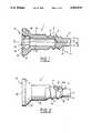
- FIG. 1is a view in axial section on a highly magnified scale, of an embodiment of the percutaneous bone screw according to the invention.
- FIG. 2is a side view on the same scale as FIG. 1 of the screw according to the invention.
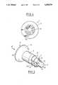
- FIG. 3is a perspective view on the same scale as FIG. 1 and FIG. 2 of the percutaneous bone screw according to the invention.
- FIG. 4is a front view of the head of the screw along direction F of FIG. 3.
- FIG. 5is a schematic view in elevation of the head of a patient on which a stereotaxy frame is placed, this frame being supported by cranial screws according to the invention.
- FIG. 6is a view from above corresponding to FIG. 5, showing the positioning of the frame.
- FIG. 7is a view in partial elevation of the frame and of one of the screws of the device of FIG. 5 and FIG. 6.
- FIG. 8is a view which is a half partial section and half elevation of the wall of the neurocranium and of a screw anchored in the latter, ready to receive a frame such as the one in FIG. 5 and FIG. 6.
- the percutaneous bone screw 1 represented in the drawingsis intended to receive a support such as in particular a stereotaxy frame 10 (FIG. 5 and FIG. 6). It is capable of receiving other applications, for example for maxillo facial surgery or any subcutaneous bone surgery.
- this bone screwis arranged in order to be able to hold back any mucosa or aponeurosis behind a bone, without causing damage to it.
- the screw 1with axis XX, comprises an end formed by a dog point 2 having a plane surface 3 transverse to the axis XX and a cylindrical lateral surface 4, connected to the plane surface 3 by a rounded annular radius 5.
- This screwalso comprises a threaded part 6 fitted with threads 7, contiguous with the dog point 2 and in which a self-tapping zone 8 is made.
- This self-tapping zoneis constituted by at least one groove formed by a flat 8, there being for example two as in the example represented, delimiting an interruption of the threads 7 and bordered by sharp edges 8a, these flats 8 terminating at the base of the dog point 2 or in the vicinity of the latter.
- the screw 1furthermore comprises a cylindrical smooth part 9, arranged between its threaded part 7 and a head 11 which isadapted in order to receive a manipulating tool (screwdriver) which is not represented.
- the cylindrical smooth part 9is connected to the head 11 by a plane annular zone 12, which is inclined to the axis XX and to the surface of the smooth part 9 by an appropriate angle.
- the annular zone 12is connected to the transverse surface 13 of the head 11 by a cylindrical part 14 which is concentric with the axis XX.
- the length (1) of the dog point 2is at least equal to its diameter (d) (substantially greater than d in FIG. 1 to 3).
- the bore 17is adapted in order to receive equipment for joining to an article which is to be supported by screws 1 anchored on the patient, such as the article 19 for interface with the stereotaxy frame 10 (FIG. 6 and FIG. 7).
- the neurosurgeon or doctor who places the necessary screws 1anchors them in succession in the wall of the bone 20 with an inclination demanded by the frame 10 on the surface of the skin18 (see FIG. 8) and of the cranial bone 19.
- the self-tapping part 8bores and taps the necessary passage hole in the neurocranium 20, then the rounded dog point 2, after having passed throughthe bone 20, slightly pushes the dura mater 21 back. The latter locally takes the position represented in FIG. 8 without damage to it, and consequently without risk by the introduction of the screw 1 of causing a lesion of the subjacent organs 22.
- the boring of the neurocranium 20 by the self-tapping part 8 and the threaded zone 6are capable of causing theappearance of bone splinters, which should not injure the dura mater 21.
- This resultis made possible by the rounded shape of the terminal dog point 2, which gently pushes the dura mater 21 back without provoking any harm to it and moves the splinters apart under its pressure.
- the smooth parts 9 and 12 in contact with the skin 18are not capable of damaging the latter with which they remain in contact in their final position, as represented in FIG. 7 in which the head 11 juts out from the skin 18.
- the choice of the arrangement of the smooth parts 9 and 12allows, taking into account the inclination of the screws 1 demanded by its frame 10, theskin of the cranium 18 not to be damaged and good support on the neurocranium 20 to be provided.
- This solid anchoringtherefore allows easy repositioning of a frame such as10, for the purposes of the planned investigations.
- the joining equipment between the frame 10 and the screws 1comprise in theexample illustrated in FIG. 6 and FIG. 7, an interface article 19 fitted with a central disc 21 on either side of which two anterior 19a and posterior 19b parts jut out axially.
- An interface article such as 19allows a frame 10 be mounted on the screws 1 using four corner pillars 23 fixed to the frame and which each carry a transverse barrel 24 drilled on either side with an axial hole for receiving the posterior part 19a.
- the surgeonintroduces a screwdriver axially in the barrel 24 placed on its support pillar 23, performs the screwing, removes the screwdriver, and places the interface article 19 between the screw 1 and the barrel 24 by introducing therein respectively the parts 19a and 19b.
- the neurosurgeonAfter having carried out the planned examinations and investigations, the neurosurgeon removes the frame 10 and the joining equipment 19, the screws1 remaining anchored in place until the next examination.
- the percutaneous screws 1are advantageously made of titanium, which makes it possible not to deform the radiological or MRI images (Artefact).
- the screw 1 according to the inventionhas the abovementioned advantages, which are of particular interest for the various applications of stereotaxy: diagnosis of cerebral lesions, their locating for their subsequent multi-beam irradiation, treatment of benign lesions, placing stimulators in the brain, or electrodes in order to find the positions from where electrical discharges come during epileptic fits etc.
- the inventionis not limited to the embodiment described and can include other embodiments.
- the number of self-tapping grooves 8can thus vary: there are in particular advantageously three of them, angularly separated by approximately 120 degrees.
- the rounded shape of the dog point 2may vary widely: it may alsoin particular be spherical or conical with a rounded apex.
- the screw illustrated in the drawingsmay be modified by replacing the cylindrical lateral surface 4 by a conical or spherical surface.
- the self-tapping zonemay also be removed from the screw.
Landscapes
- Health & Medical Sciences (AREA)
- Orthopedic Medicine & Surgery (AREA)
- Surgery (AREA)
- Life Sciences & Earth Sciences (AREA)
- Heart & Thoracic Surgery (AREA)
- Animal Behavior & Ethology (AREA)
- Engineering & Computer Science (AREA)
- Biomedical Technology (AREA)
- Neurology (AREA)
- Medical Informatics (AREA)
- Molecular Biology (AREA)
- Nuclear Medicine, Radiotherapy & Molecular Imaging (AREA)
- General Health & Medical Sciences (AREA)
- Public Health (AREA)
- Veterinary Medicine (AREA)
- Surgical Instruments (AREA)
- Apparatus For Radiation Diagnosis (AREA)
- Magnetic Resonance Imaging Apparatus (AREA)
Abstract
Description
The subject of the present invention is a percutaneous bone screw, intended to support in particular a stereotaxy frame allowing investigation inside the neurocranium of a patient.
The precise spatial reposition of the brain to millimeter accuracy is necessary for implementing certain therapeutic techniques, for example surgery in stereotaxic conditions, or repeated irradiation for tumour-related illnesses or vascular malformations (angiomas).
Positioning of a reference frame, which may or may not be metal, fixed to the neurocranium allows investigations to be performed in a topographically superposable manner: arteriography, ventriculography, body scanning, MRI, and performing treatments, which constitutes the principle of stereotaxy. But this assumes that the frame, and therefore the fastening of the cranial anchoring, is repositioned each time.
Two technical methods are possible for this purpose:
either a position-finding process which is redone each time, using three-dimensional coordinate computation. This computation is currently relatively easy but the refitting does not always have millimeter precision, taking into account that the needles of the frame are difficult to reposition in the holes of the bone.
This has obvious resulting drawbacks from the point of view of the patient: his neurocranium must actually be subjected to piercings, incisions of the scalp and local anaesthetics repeated on each refitting, giving rise to infection risks and painful discomfort. For the surgeon, repeating these fitting operations requires considerable time trying to find the position accurately.
Or precise repositioning, to millimeter accuracy, of the frame in the osseous structure of the neurocranium using percutaneous bone screws.
The latter technique, undoubtedly the most accurate, demands iterative refitting of the frame on the neurocranium, on percutaneous screws (that is to say, screws whose head projects out of the skin of the patient) which are anchored in the osseous structure, for several days on end or possibly several days per week for several weeks, during sequential irradiations.
The aim of the invention is therefore to provide a satisfactory solution to this problem, by producing percutaneous bone screw which can stay in place in the neurocranium of the patient after an initial accurate position-finding process, for several weeks for the purpose of investigation or therapy which can be well tolerated by the skin and bone, and allows iterative repositioning of the frame.
According to the invention, the percutaneous bone screw includes an end formed by a rounded and blunt dog point, and in its threaded part contiguous with the dog point, a self-tapping zone is made which is constituted by at least one groove formed by a flat bordered by sharp edges, and which terminates in the vicinity of the base of the dog point.
The rounded shape of the end of the screw avoids, during for example cranial anchoring of the screw, any risk of damage to the subjacent aponeurosis or mucosa such as the dura mater which forms an envelope for the brain. This membrane is actually slightly pushed back by the rounded dog point of the screw, ruling out any risk of oedema which could be caused by a cutting edge and limiting a possible inflammatory or haemorrhagic reaction.
The fact that the screw is provided with a self-tapping part avoids the necessity of boring and tapping the hole of the bone.
According to one possible embodiment of the invention, the dog point has a plane transverse surface and a cylindrical lateral surface connected to the plane surface by a rounded annular radius.
The screw advantageously comprises a cylindrical smooth part, arranged between its threaded part and a head adapted in order to receive a manipulating tool. This smooth part is transcutaneous when the screw is in place, for the purpose of the trophicity of the skin.
Other characteristics and advantages of the invention will appear during the description which follows, and which is made with reference to the attached drawings which illustrate an embodiment thereof by way of non-limiting example.
FIG. 1 is a view in axial section on a highly magnified scale, of an embodiment of the percutaneous bone screw according to the invention.
FIG. 2 is a side view on the same scale as FIG. 1 of the screw according to the invention.
FIG. 3 is a perspective view on the same scale as FIG. 1 and FIG. 2 of the percutaneous bone screw according to the invention.
FIG. 4 is a front view of the head of the screw along direction F of FIG. 3.
FIG. 5 is a schematic view in elevation of the head of a patient on which a stereotaxy frame is placed, this frame being supported by cranial screws according to the invention.
FIG. 6 is a view from above corresponding to FIG. 5, showing the positioning of the frame.
FIG. 7 is a view in partial elevation of the frame and of one of the screws of the device of FIG. 5 and FIG. 6.
FIG. 8 is a view which is a half partial section and half elevation of the wall of the neurocranium and of a screw anchored in the latter, ready to receive a frame such as the one in FIG. 5 and FIG. 6.
thepercutaneous bone screw 1 represented in the drawings is intended to receive a support such as in particular a stereotaxy frame 10 (FIG. 5 and FIG. 6). It is capable of receiving other applications, for example for maxillo facial surgery or any subcutaneous bone surgery. In general, this bone screw is arranged in order to be able to hold back any mucosa or aponeurosis behind a bone, without causing damage to it.
Thescrew 1, with axis XX, comprises an end formed by adog point 2 having aplane surface 3 transverse to the axis XX and a cylindricallateral surface 4, connected to theplane surface 3 by a rounded annular radius 5.This screw also comprises a threadedpart 6 fitted withthreads 7, contiguous with thedog point 2 and in which a self-tapping zone 8 is made. This self-tapping zone is constituted by at least one groove formed by a flat 8, there being for example two as in the example represented, delimiting an interruption of thethreads 7 and bordered bysharp edges 8a, theseflats 8 terminating at the base of thedog point 2 or in the vicinity of the latter. Thescrew 1 furthermore comprises a cylindrical smooth part 9, arranged between its threadedpart 7 and ahead 11 which isadapted in order to receive a manipulating tool (screwdriver) which is not represented. The cylindrical smooth part 9 is connected to thehead 11 by a planeannular zone 12, which is inclined to the axis XX and to the surface of the smooth part 9 by an appropriate angle. Theannular zone 12 is connected to thetransverse surface 13 of thehead 11 by acylindrical part 14 which is concentric with the axis XX.
The length (1) of thedog point 2 is at least equal to its diameter (d) (substantially greater than d in FIG. 1 to 3).
In thescrew 1 there is made an axial hollow 15 extending from thehead 11,constituted by ahousing 16 which is limited by thesurface 13 and profiledin order to receive a screwing tool, and by anaxial bore 17 which extends thehousing 16 in the direction of theterminal dog point 2. Thebore 17 is adapted in order to receive equipment for joining to an article which is to be supported byscrews 1 anchored on the patient, such as thearticle 19 for interface with the stereotaxy frame 10 (FIG. 6 and FIG. 7).
In the case of the use of thescrew 1 according to the invention as a support for astereotaxy frame 10, the neurosurgeon or doctor who places thenecessary screws 1 anchors them in succession in the wall of thebone 20 with an inclination demanded by theframe 10 on the surface of the skin18 (see FIG. 8) and of thecranial bone 19. During the screwing, the self-tappingpart 8 bores and taps the necessary passage hole in theneurocranium 20, then therounded dog point 2, after having passed throughthebone 20, slightly pushes thedura mater 21 back. The latter locally takes the position represented in FIG. 8 without damage to it, and consequently without risk by the introduction of thescrew 1 of causing a lesion of thesubjacent organs 22. The boring of theneurocranium 20 by the self-tappingpart 8 and the threadedzone 6 are capable of causing theappearance of bone splinters, which should not injure thedura mater 21. This result is made possible by the rounded shape of theterminal dog point 2, which gently pushes thedura mater 21 back without provoking any harm to it and moves the splinters apart under its pressure.
For their part, thesmooth parts 9 and 12, in contact with theskin 18 are not capable of damaging the latter with which they remain in contact in their final position, as represented in FIG. 7 in which thehead 11 juts out from theskin 18.
The choice of the arrangement of thesmooth parts 9 and 12 allows, taking into account the inclination of thescrews 1 demanded by itsframe 10, theskin of thecranium 18 not to be damaged and good support on theneurocranium 20 to be provided.
This solid anchoring therefore allows easy repositioning of a frame such as10, for the purposes of the planned investigations.
The joining equipment between theframe 10 and thescrews 1 comprise in theexample illustrated in FIG. 6 and FIG. 7, aninterface article 19 fitted with acentral disc 21 on either side of which two anterior 19a and posterior 19b parts jut out axially. An interface article such as 19 allows aframe 10 be mounted on thescrews 1 using fourcorner pillars 23 fixed to the frame and which each carry atransverse barrel 24 drilled on either side with an axial hole for receiving the posterior part 19a.
In order to place ascrew 1 in thecranium 20 of the patient, the surgeon introduces a screwdriver axially in thebarrel 24 placed on itssupport pillar 23, performs the screwing, removes the screwdriver, and places theinterface article 19 between thescrew 1 and thebarrel 24 by introducing therein respectively theparts 19a and 19b.
After having carried out the planned examinations and investigations, the neurosurgeon removes theframe 10 and thejoining equipment 19, the screws1 remaining anchored in place until the next examination.
Thepercutaneous screws 1 are advantageously made of titanium, which makes it possible not to deform the radiological or MRI images (Artefact).
In the scope of its use as a support for a stereotaxic system such as 10, thescrew 1 according to the invention has the abovementioned advantages, which are of particular interest for the various applications of stereotaxy: diagnosis of cerebral lesions, their locating for their subsequent multi-beam irradiation, treatment of benign lesions, placing stimulators in the brain, or electrodes in order to find the positions from where electrical discharges come during epileptic fits etc.
The invention is not limited to the embodiment described and can include other embodiments. The number of self-tappinggrooves 8 can thus vary: there are in particular advantageously three of them, angularly separated by approximately 120 degrees.
Moreover, the rounded shape of thedog point 2 may vary widely: it may alsoin particular be spherical or conical with a rounded apex. The screw illustrated in the drawings may be modified by replacing the cylindricallateral surface 4 by a conical or spherical surface. The self-tapping zonemay also be removed from the screw.
Claims (6)
1. A percutaneous bone screw (1) for supporting a stereotaxy frame (10) on the cranium of a patient comprising:
a threaded part (6) having a self-tapping zone which is constituted by at least one groove formed by a flat (8) bordered by sharp edges (8a) which terminates adjacent one end of said threaded part, and a non-threaded dog point (2) contiguous with said one end, said dog point (2) having a plane transverse surface (3) and a cylindrical lateral surface (4) connected to said plane surface by a rounded annular radius (5), said transverse surface having a diameter substantially equal to the diameter of said cylindrical lateral surface.
2. The screw according to claim 1 wherein said threaded part (6) has three self-tapping zones (8) angularly separated by approximately 120 degrees.
3. The screw according to claim 2 further comprising a head opposite said dog point, a smooth cylindrical part (9), arranged between said threaded part (6) and said head (11) adapted to receive a manipulating tool.
4. The screw according to claim 3 wherein said smooth cylindrical part (9) is connected to said head of the screw (1) by an annular zone (12) which is inclined with respect to a longitudinal axis (XX) of the screw.
5. The screw according to claim 4 further comprising an axial hollow (15) extending from said head (11), constituted by a housing (16) which is profiled in order to receive a screwing tool, and by an axial bore (17) which extends in the direction of said dog point (2), said bore being adapted to receive equipment (18) for joining to a stereotaxy frame (10).
6. The screw according to claim 1 wherein said dog point (2) has a length that is equal to or greater than the diameter of said cylindrical lateral surface.
Applications Claiming Priority (2)
| Application Number | Priority Date | Filing Date | Title |
|---|---|---|---|
| FR9112571AFR2682281B1 (en) | 1991-10-11 | 1991-10-11 | PERCUTANEOUS SCREW, INTENDED TO SUPPORT IN PARTICULAR A STEREOTAXY FRAMEWORK |
| FR9112571 | 1991-10-11 |
Publications (1)
| Publication Number | Publication Date |
|---|---|
| US5300076Atrue US5300076A (en) | 1994-04-05 |
Family
ID=9417842
Family Applications (1)
| Application Number | Title | Priority Date | Filing Date |
|---|---|---|---|
| US07/959,129Expired - LifetimeUS5300076A (en) | 1991-10-11 | 1992-10-09 | Percutaneous bone screw for supporting a stereotaxy frame |
Country Status (4)
| Country | Link |
|---|---|
| US (1) | US5300076A (en) |
| EP (1) | EP0537060A1 (en) |
| JP (1) | JPH06233762A (en) |
| FR (1) | FR2682281B1 (en) |
Cited By (94)
| Publication number | Priority date | Publication date | Assignee | Title |
|---|---|---|---|---|
| US5634929A (en)* | 1993-04-16 | 1997-06-03 | Oregon Neuro-Medical Technology, Inc. | Apparatus for stereotactic radiosurgery and fractionated radiation therapy |
| US5643264A (en)* | 1995-09-13 | 1997-07-01 | Danek Medical, Inc. | Iliac screw |
| US5697979A (en)* | 1995-05-19 | 1997-12-16 | Pignataro; Anthony S. | Method and apparatus for securing a hair prosthesis to the human head |
| US5702445A (en)* | 1993-04-27 | 1997-12-30 | Medevelop Ab | Anchoring element for implantation in tissue, for holding prosthesis, artificial joint components or the like |
| US5728106A (en)* | 1993-04-16 | 1998-03-17 | Oregon Neuro-Medical Technology, Inc. | Radio-transparent system for stereotactic radiosurgery and fractionated radiation therapy |
| US5782832A (en)* | 1996-10-01 | 1998-07-21 | Surgical Dynamics, Inc. | Spinal fusion implant and method of insertion thereof |
| FR2758972A1 (en)* | 1997-02-04 | 1998-08-07 | Eos Medical | THREADED HEAD SCREW DEVICE FOR ALLOWING FIXING OF SMALL BONE FRAGMENTS |
| US5842865A (en)* | 1997-09-12 | 1998-12-01 | Sulzer Calcitek Inc. | Self-tapping implant with multiple concave tapping channels |
| US5871486A (en)* | 1993-01-21 | 1999-02-16 | Acumed, Inc. | Variable pitch bone screw |
| US5885299A (en)* | 1994-09-15 | 1999-03-23 | Surgical Dynamics, Inc. | Apparatus and method for implant insertion |
| US5897319A (en)* | 1997-09-12 | 1999-04-27 | Sulzer Calcitek Inc. | Self-tapping implant with helical flutes |
| US5906616A (en)* | 1994-09-15 | 1999-05-25 | Surgical Dynamics, Inc. | Conically shaped anterior fusion cage and method of implantation |
| DE19750493A1 (en)* | 1997-11-14 | 1999-06-02 | Medos Medizintechnik Gmbh | Fracture stabilization implant and screw for use in surgery |
| US5964768A (en)* | 1993-01-21 | 1999-10-12 | Acumed, Inc. | Tapered bone screw with continuously varying pitch |
| US5968098A (en)* | 1996-10-22 | 1999-10-19 | Surgical Dynamics, Inc. | Apparatus for fusing adjacent bone structures |
| US6001101A (en)* | 1994-07-05 | 1999-12-14 | Depuy France | Screw device with threaded head for permitting the coaptation of two bone fragments |
| US6016727A (en)* | 1997-02-28 | 2000-01-25 | Sofamor Danek Properties, Inc. | Recess drive bone screw and cooperable driving tool |
| US6030162A (en)* | 1998-12-18 | 2000-02-29 | Acumed, Inc. | Axial tension screw |
| US6063088A (en)* | 1997-03-24 | 2000-05-16 | United States Surgical Corporation | Method and instrumentation for implant insertion |
| US6190414B1 (en) | 1996-10-31 | 2001-02-20 | Surgical Dynamics Inc. | Apparatus for fusion of adjacent bone structures |
| US6251140B1 (en) | 1998-05-27 | 2001-06-26 | Nuvasive, Inc. | Interlocking spinal inserts |
| US6290724B1 (en) | 1998-05-27 | 2001-09-18 | Nuvasive, Inc. | Methods for separating and stabilizing adjacent vertebrae |
| US6299615B1 (en) | 1993-01-21 | 2001-10-09 | Acumed, Inc. | System for fusing joints |
| US6327491B1 (en)* | 1998-07-06 | 2001-12-04 | Neutar, Llc | Customized surgical fixture |
| US20020038126A1 (en)* | 2000-09-24 | 2002-03-28 | Medtronic, Inc. | Surgical reference frame fixation device with cannulated post and method of use |
| US6368325B1 (en) | 1998-05-27 | 2002-04-09 | Nuvasive, Inc. | Bone blocks and methods for inserting bone blocks into intervertebral spaces |
| US6459927B1 (en) | 1999-07-06 | 2002-10-01 | Neutar, Llc | Customizable fixture for patient positioning |
| US6468277B1 (en) | 2000-04-04 | 2002-10-22 | Ethicon, Inc. | Orthopedic screw and method |
| US20030014054A1 (en)* | 1993-01-21 | 2003-01-16 | Huebner Randall J. | System for fusing joints |
| US20030028193A1 (en)* | 2001-07-05 | 2003-02-06 | Weil Lowell Scott | Self-tapping screw for small-bone surgery |
| US6517542B1 (en) | 1999-08-04 | 2003-02-11 | The Cleveland Clinic Foundation | Bone anchoring system |
| US6585740B2 (en) | 1998-11-26 | 2003-07-01 | Synthes (U.S.A.) | Bone screw |
| US20030196671A1 (en)* | 2002-04-17 | 2003-10-23 | Ricardo Sasso | Instrumentation and method for mounting a surgical navigation reference device to a patient |
| US20040019265A1 (en)* | 2002-07-29 | 2004-01-29 | Mazzocchi Rudy A. | Fiducial marker devices, tools, and methods |
| US20040030237A1 (en)* | 2002-07-29 | 2004-02-12 | Lee David M. | Fiducial marker devices and methods |
| US20040092928A1 (en)* | 2002-04-17 | 2004-05-13 | Ricardo Sasso | Instrumentation and method for performing image-guided spinal surgery using an anterior surgical approach |
| WO2004045465A1 (en)* | 2002-11-21 | 2004-06-03 | Michel Collette | Anchoring screw for a relay strip or suture |
| US20040167393A1 (en)* | 2003-02-25 | 2004-08-26 | Solar Matthew S. | Fiducial marker devices, tools, and methods |
| US20050101961A1 (en)* | 2003-11-12 | 2005-05-12 | Huebner Randall J. | Bone screws |
| US6899734B2 (en) | 2001-03-23 | 2005-05-31 | Howmedica Osteonics Corp. | Modular implant for fusing adjacent bone structure |
| US20050119566A1 (en)* | 2002-04-17 | 2005-06-02 | Ricardo Sasso | Instrumentation and method for mounting a surgical navigation reference device to a patient |
| US20050137598A1 (en)* | 2003-12-23 | 2005-06-23 | Stefan Auth | Self-drilling bone screw |
| US6923814B1 (en) | 2001-10-30 | 2005-08-02 | Nuvasive, Inc. | System and methods for cervical spinal fusion |
| US20050171562A1 (en)* | 2002-06-11 | 2005-08-04 | Criscuolo Christopher J. | Hernia mesh tacks |
| US20050187636A1 (en)* | 2004-02-19 | 2005-08-25 | Graham Michael E. | Sinus tarsi implant |
| US20060190088A1 (en)* | 2005-02-23 | 2006-08-24 | Parks Brent G | Prosthesis for correction of flatfoot deformity |
| USD530423S1 (en) | 2005-03-29 | 2006-10-17 | Nuvasive, Inc. | Intervertebral implant |
| US7235079B2 (en) | 2004-11-18 | 2007-06-26 | Acumed Llc | Composite bone fasteners |
| US20080021475A1 (en)* | 2006-07-24 | 2008-01-24 | Steven Alan Lawrie | Orthopaedic appliances |
| US20080065223A1 (en)* | 2000-07-17 | 2008-03-13 | Nuvasive, Inc. | Stackable spinal support system |
| US20080114376A1 (en)* | 1999-03-07 | 2008-05-15 | Active Implants Corporation | Method and apparatus for computerized surgery |
| WO2009007574A3 (en)* | 2007-06-22 | 2009-03-05 | Alcis | Stereotaxy rigid frame |
| US20090099664A1 (en)* | 2007-10-16 | 2009-04-16 | Forrester Perry C | Subtalar implant and kit |
| US7544208B1 (en) | 2004-05-03 | 2009-06-09 | Theken Spine, Llc | Adjustable corpectomy apparatus |
| USD599019S1 (en) | 2008-03-07 | 2009-08-25 | Nuvasive, Inc. | Spinal fusion implant |
| US7618423B1 (en) | 2002-06-15 | 2009-11-17 | Nuvasive, Inc. | System and method for performing spinal fusion |
| US20100179655A1 (en)* | 2009-01-12 | 2010-07-15 | Noah Hansell | Expandable Vertebral Prosthesis |
| US7776049B1 (en) | 2002-10-02 | 2010-08-17 | Nuvasive, Inc. | Spinal implant inserter, implant, and method |
| US20100211113A1 (en)* | 2009-02-17 | 2010-08-19 | Jon Olson | Bone Screw With Channels |
| US20100217280A1 (en)* | 2009-02-26 | 2010-08-26 | Schuele Matthias E | Method and Apparatus for a Radiolucent and MRI Compatible Cranial Stabilization Pin |
| US7787934B2 (en) | 2002-07-29 | 2010-08-31 | Medtronic, Inc. | Fiducial marker devices, tools, and methods |
| US20100298942A1 (en)* | 2005-04-21 | 2010-11-25 | Noah Hansell | Expandable Vertebral Prosthesis |
| US7918876B2 (en) | 2003-03-24 | 2011-04-05 | Theken Spine, Llc | Spinal implant adjustment device |
| US7918891B1 (en) | 2004-03-29 | 2011-04-05 | Nuvasive Inc. | Systems and methods for spinal fusion |
| US8070786B2 (en) | 1993-01-21 | 2011-12-06 | Acumed Llc | System for fusing joints |
| US8287597B1 (en) | 2009-04-16 | 2012-10-16 | Nuvasive, Inc. | Method and apparatus for performing spine surgery |
| USD671645S1 (en) | 2007-09-18 | 2012-11-27 | Nuvasive, Inc. | Intervertebral implant |
| US8328851B2 (en) | 2005-07-28 | 2012-12-11 | Nuvasive, Inc. | Total disc replacement system and related methods |
| US20130131678A1 (en)* | 2010-06-03 | 2013-05-23 | The University Of North Carolina At Chapel Hill | Threaded elastic intramedullary nails devices and methods |
| US8623088B1 (en) | 2005-07-15 | 2014-01-07 | Nuvasive, Inc. | Spinal fusion implant and related methods |
| US8673005B1 (en) | 2007-03-07 | 2014-03-18 | Nuvasive, Inc. | System and methods for spinal fusion |
| US8844536B1 (en) | 2010-08-24 | 2014-09-30 | Pro Med Instruments Gmbh | Locking apparatus for a head fixation device |
| USD721808S1 (en) | 2011-11-03 | 2015-01-27 | Nuvasive, Inc. | Intervertebral implant |
| USD731063S1 (en) | 2009-10-13 | 2015-06-02 | Nuvasive, Inc. | Spinal fusion implant |
| US20150209081A1 (en)* | 2012-07-25 | 2015-07-30 | Orthofix S.R.I. | Elongated pin for an external modular fixation system for temporary and/or permanent fixation applications and external modular fixation system |
| US9095444B2 (en) | 2009-07-24 | 2015-08-04 | Warsaw Orthopedic, Inc. | Implant with an interference fit fastener |
| USD741488S1 (en) | 2006-07-17 | 2015-10-20 | Nuvasive, Inc. | Spinal fusion implant |
| US9161793B2 (en) | 1993-01-21 | 2015-10-20 | Acumed Llc | Axial tension screw |
| US9168152B2 (en) | 2008-02-29 | 2015-10-27 | Nuvasive, Inc. | Implants and methods for spinal fusion |
| US9179875B2 (en) | 2009-12-21 | 2015-11-10 | Sherwin Hua | Insertion of medical devices through non-orthogonal and orthogonal trajectories within the cranium and methods of using |
| US9198765B1 (en) | 2011-10-31 | 2015-12-01 | Nuvasive, Inc. | Expandable spinal fusion implants and related methods |
| USD754346S1 (en) | 2009-03-02 | 2016-04-19 | Nuvasive, Inc. | Spinal fusion implant |
| US9351845B1 (en) | 2009-04-16 | 2016-05-31 | Nuvasive, Inc. | Method and apparatus for performing spine surgery |
| US9387090B2 (en) | 2009-03-12 | 2016-07-12 | Nuvasive, Inc. | Vertebral body replacement |
| US20160242874A1 (en)* | 2015-02-23 | 2016-08-25 | Maurice Valen | Implantable surgical screw for bone reconstruction |
| US9687357B2 (en) | 2009-03-12 | 2017-06-27 | Nuvasive, Inc. | Vertebral body replacement |
| US9833289B2 (en) | 2009-02-26 | 2017-12-05 | pro med instruments, GmbH | Method and apparatus for a radiolucent and MRI compatible cranial stabilization pin |
| WO2019126019A1 (en)* | 2017-12-22 | 2019-06-27 | Medos International Sàrl | Bone screw with cutting tip |
| US10417357B2 (en) | 2012-03-08 | 2019-09-17 | Neutar, Llc | Patient and procedure customized fixation and targeting devices for stereotactic frames |
| US11160580B2 (en) | 2019-04-24 | 2021-11-02 | Spine23 Inc. | Systems and methods for pedicle screw stabilization of spinal vertebrae |
| US11376050B2 (en) | 2017-06-27 | 2022-07-05 | Medos International Sarl | Bone screw |
| US11759238B2 (en) | 2008-10-01 | 2023-09-19 | Sherwin Hua | Systems and methods for pedicle screw stabilization of spinal vertebrae |
| US12076058B2 (en) | 2021-05-12 | 2024-09-03 | Spine23 Inc. | Systems and methods for pedicle screw stabilization of spinal vertebrae |
| US12268422B2 (en) | 2019-11-27 | 2025-04-08 | Spine23 Inc. | Systems, devices and methods for treating a lateral curvature of a spine |
Families Citing this family (4)
| Publication number | Priority date | Publication date | Assignee | Title |
|---|---|---|---|---|
| FR2717066B1 (en)* | 1994-03-08 | 1996-05-15 | Jean Taylor | Bone implant especially for vertebrae pedicle. |
| US5700264A (en)* | 1996-07-01 | 1997-12-23 | Zucherman; James F. | Apparatus and method for preparing a site for an interbody fusion implant |
| DE102007029364A1 (en)* | 2007-06-26 | 2009-01-02 | Siemens Ag | A method of determining access to an area of a brain |
| WO2009006935A1 (en)* | 2007-07-06 | 2009-01-15 | Karolinska Institutet Innovations Ab | Stereotactic surgery system |
Citations (13)
| Publication number | Priority date | Publication date | Assignee | Title |
|---|---|---|---|---|
| US4042342A (en)* | 1974-01-14 | 1977-08-16 | Muenchinger Herman G | Blanks for making self-thread forming threaded fasteners |
| FR2382225A1 (en)* | 1977-03-04 | 1978-09-29 | Siemens Ag | ADAPTER MOUNTED IN THE SKULL OF A PATIENT AND INTENDED TO RECEIVE A PRESSURE TRANSDUCER |
| US4175555A (en)* | 1977-02-24 | 1979-11-27 | Interfix Limited | Bone screw |
| SU921556A1 (en)* | 1980-07-07 | 1982-04-23 | Всесоюзный научно-исследовательский и испытательный институт медицинской техники | Apparatus for fixing surgical instrument |
| SU955916A1 (en)* | 1980-10-30 | 1982-09-07 | за вители | Stereotaxic apparatus |
| SU1061807A1 (en)* | 1982-02-18 | 1983-12-23 | Edinak Aleksej N | Apparatus for perosseous osteosynthesis |
| CH643131A5 (en)* | 1981-08-03 | 1984-05-30 | Jaquet Orthopedie | Transcutaneous pin for fixation of a bone fragment or element |
| US4537185A (en)* | 1983-06-10 | 1985-08-27 | Denis P. Stednitz | Cannulated fixation screw |
| EP0323429A1 (en)* | 1987-12-30 | 1989-07-05 | Alain Guinounet | Bone plate locking screw and its fabrication process |
| EP0195455B1 (en)* | 1985-03-22 | 1990-02-28 | CODMAN & SHURTLEFF INC. | Cranial screw |
| EP0373733A1 (en)* | 1988-12-10 | 1990-06-20 | IMZ-Fertigungs- und Vertriebsgesellschaft für dentale Technologie mbH | Implantable fixation means for extra-oral applications |
| US4978350A (en)* | 1986-10-13 | 1990-12-18 | Jaquet Orthopedie S.A. | Transcutaneous pin for fixation of a bone part or fragment |
| US5122132A (en)* | 1991-08-01 | 1992-06-16 | Bremer Medical, Inc. | Skull pin with enhanced shear resistance |
- 1991
- 1991-10-11FRFR9112571Apatent/FR2682281B1/ennot_activeExpired - Fee Related
- 1992
- 1992-10-05EPEP92402713Apatent/EP0537060A1/ennot_activeWithdrawn
- 1992-10-09USUS07/959,129patent/US5300076A/ennot_activeExpired - Lifetime
- 1992-10-12JPJP4299299Apatent/JPH06233762A/ennot_activeWithdrawn
Patent Citations (13)
| Publication number | Priority date | Publication date | Assignee | Title |
|---|---|---|---|---|
| US4042342A (en)* | 1974-01-14 | 1977-08-16 | Muenchinger Herman G | Blanks for making self-thread forming threaded fasteners |
| US4175555A (en)* | 1977-02-24 | 1979-11-27 | Interfix Limited | Bone screw |
| FR2382225A1 (en)* | 1977-03-04 | 1978-09-29 | Siemens Ag | ADAPTER MOUNTED IN THE SKULL OF A PATIENT AND INTENDED TO RECEIVE A PRESSURE TRANSDUCER |
| SU921556A1 (en)* | 1980-07-07 | 1982-04-23 | Всесоюзный научно-исследовательский и испытательный институт медицинской техники | Apparatus for fixing surgical instrument |
| SU955916A1 (en)* | 1980-10-30 | 1982-09-07 | за вители | Stereotaxic apparatus |
| CH643131A5 (en)* | 1981-08-03 | 1984-05-30 | Jaquet Orthopedie | Transcutaneous pin for fixation of a bone fragment or element |
| SU1061807A1 (en)* | 1982-02-18 | 1983-12-23 | Edinak Aleksej N | Apparatus for perosseous osteosynthesis |
| US4537185A (en)* | 1983-06-10 | 1985-08-27 | Denis P. Stednitz | Cannulated fixation screw |
| EP0195455B1 (en)* | 1985-03-22 | 1990-02-28 | CODMAN & SHURTLEFF INC. | Cranial screw |
| US4978350A (en)* | 1986-10-13 | 1990-12-18 | Jaquet Orthopedie S.A. | Transcutaneous pin for fixation of a bone part or fragment |
| EP0323429A1 (en)* | 1987-12-30 | 1989-07-05 | Alain Guinounet | Bone plate locking screw and its fabrication process |
| EP0373733A1 (en)* | 1988-12-10 | 1990-06-20 | IMZ-Fertigungs- und Vertriebsgesellschaft für dentale Technologie mbH | Implantable fixation means for extra-oral applications |
| US5122132A (en)* | 1991-08-01 | 1992-06-16 | Bremer Medical, Inc. | Skull pin with enhanced shear resistance |
Non-Patent Citations (4)
| Title |
|---|
| World Patent Index Latest Section PQ, Apr. 23, 1982 Derwent Publications Ltd., London GB; Class P31, AN 83 D0221K/09 & SU A 921 556 (Med Tech Res Inst) 7 Juillet 1980.* |
| World Patent Index Latest Section PQ, Apr. 23, 1982 Derwent Publications Ltd., London GB; Class P31, AN 83-D0221K/09 & SU-A-921 556 (Med Tech Res Inst) 7 Juillet 1980. |
| World Patents Index Latest Section PQ, Sep. 7, 1982 Derwent Publications Ltd. London, GB; Class P31, AN 83 710140/28 & SU A 955 916 (MATVEEV) Oct. 30, 1990.* |
| World Patents Index Latest Section PQ, Sep. 7, 1982 Derwent Publications Ltd. London, GB; Class P31, AN 83-710140/28 & SU-A-955 916 (MATVEEV) Oct. 30, 1990. |
Cited By (204)
| Publication number | Priority date | Publication date | Assignee | Title |
|---|---|---|---|---|
| US8070786B2 (en) | 1993-01-21 | 2011-12-06 | Acumed Llc | System for fusing joints |
| US6299615B1 (en) | 1993-01-21 | 2001-10-09 | Acumed, Inc. | System for fusing joints |
| US20030014054A1 (en)* | 1993-01-21 | 2003-01-16 | Huebner Randall J. | System for fusing joints |
| US9161793B2 (en) | 1993-01-21 | 2015-10-20 | Acumed Llc | Axial tension screw |
| US6984235B2 (en) | 1993-01-21 | 2006-01-10 | Acumed Llc | System for fusing joints |
| US5871486A (en)* | 1993-01-21 | 1999-02-16 | Acumed, Inc. | Variable pitch bone screw |
| US5964768A (en)* | 1993-01-21 | 1999-10-12 | Acumed, Inc. | Tapered bone screw with continuously varying pitch |
| US5728106A (en)* | 1993-04-16 | 1998-03-17 | Oregon Neuro-Medical Technology, Inc. | Radio-transparent system for stereotactic radiosurgery and fractionated radiation therapy |
| US5634929A (en)* | 1993-04-16 | 1997-06-03 | Oregon Neuro-Medical Technology, Inc. | Apparatus for stereotactic radiosurgery and fractionated radiation therapy |
| US5702445A (en)* | 1993-04-27 | 1997-12-30 | Medevelop Ab | Anchoring element for implantation in tissue, for holding prosthesis, artificial joint components or the like |
| US6001101A (en)* | 1994-07-05 | 1999-12-14 | Depuy France | Screw device with threaded head for permitting the coaptation of two bone fragments |
| US5906616A (en)* | 1994-09-15 | 1999-05-25 | Surgical Dynamics, Inc. | Conically shaped anterior fusion cage and method of implantation |
| US20030114854A1 (en)* | 1994-09-15 | 2003-06-19 | Howmedica Osteonics Corp. | Conically shaped anterior fusion cage and method of implantation |
| US5885299A (en)* | 1994-09-15 | 1999-03-23 | Surgical Dynamics, Inc. | Apparatus and method for implant insertion |
| US7608105B2 (en) | 1994-09-15 | 2009-10-27 | Howmedica Osteonics Corp. | Methods of inserting conically-shaped fusion cages |
| US5697979A (en)* | 1995-05-19 | 1997-12-16 | Pignataro; Anthony S. | Method and apparatus for securing a hair prosthesis to the human head |
| US5643264A (en)* | 1995-09-13 | 1997-07-01 | Danek Medical, Inc. | Iliac screw |
| US5782832A (en)* | 1996-10-01 | 1998-07-21 | Surgical Dynamics, Inc. | Spinal fusion implant and method of insertion thereof |
| US5968098A (en)* | 1996-10-22 | 1999-10-19 | Surgical Dynamics, Inc. | Apparatus for fusing adjacent bone structures |
| US6190414B1 (en) | 1996-10-31 | 2001-02-20 | Surgical Dynamics Inc. | Apparatus for fusion of adjacent bone structures |
| FR2758972A1 (en)* | 1997-02-04 | 1998-08-07 | Eos Medical | THREADED HEAD SCREW DEVICE FOR ALLOWING FIXING OF SMALL BONE FRAGMENTS |
| US6016727A (en)* | 1997-02-28 | 2000-01-25 | Sofamor Danek Properties, Inc. | Recess drive bone screw and cooperable driving tool |
| US6063088A (en)* | 1997-03-24 | 2000-05-16 | United States Surgical Corporation | Method and instrumentation for implant insertion |
| US5897319A (en)* | 1997-09-12 | 1999-04-27 | Sulzer Calcitek Inc. | Self-tapping implant with helical flutes |
| US5842865A (en)* | 1997-09-12 | 1998-12-01 | Sulzer Calcitek Inc. | Self-tapping implant with multiple concave tapping channels |
| DE19750493A1 (en)* | 1997-11-14 | 1999-06-02 | Medos Medizintechnik Gmbh | Fracture stabilization implant and screw for use in surgery |
| US6468278B1 (en) | 1997-11-14 | 2002-10-22 | Medos Medizintechnik Gmbh | Implant for the stabilization of a fracture |
| US6368325B1 (en) | 1998-05-27 | 2002-04-09 | Nuvasive, Inc. | Bone blocks and methods for inserting bone blocks into intervertebral spaces |
| US6887248B2 (en) | 1998-05-27 | 2005-05-03 | Nuvasive, Inc. | Bone blocks and methods for inserting bone blocks into intervertebral spaces |
| US6290724B1 (en) | 1998-05-27 | 2001-09-18 | Nuvasive, Inc. | Methods for separating and stabilizing adjacent vertebrae |
| US6251140B1 (en) | 1998-05-27 | 2001-06-26 | Nuvasive, Inc. | Interlocking spinal inserts |
| US20050216088A1 (en)* | 1998-05-27 | 2005-09-29 | Nu Vasive, Inc. | Bone blocks and methods for inserting bone blocks into intervertebral spaces |
| US7776094B2 (en) | 1998-05-27 | 2010-08-17 | Nuvasive, Inc. | Spinal implants and methods for inserting spinal implants into intervertebral spaces |
| US6738657B1 (en)* | 1998-07-06 | 2004-05-18 | Neutar L.L.C. | Customized surgical fixture |
| US20030120143A1 (en)* | 1998-07-06 | 2003-06-26 | Neutar, Llc, A Maine Corporation | Customizable fixture for patient positioning |
| US6327491B1 (en)* | 1998-07-06 | 2001-12-04 | Neutar, Llc | Customized surgical fixture |
| US6585740B2 (en) | 1998-11-26 | 2003-07-01 | Synthes (U.S.A.) | Bone screw |
| US6030162A (en)* | 1998-12-18 | 2000-02-29 | Acumed, Inc. | Axial tension screw |
| US20080114376A1 (en)* | 1999-03-07 | 2008-05-15 | Active Implants Corporation | Method and apparatus for computerized surgery |
| US6459927B1 (en) | 1999-07-06 | 2002-10-01 | Neutar, Llc | Customizable fixture for patient positioning |
| US6517542B1 (en) | 1999-08-04 | 2003-02-11 | The Cleveland Clinic Foundation | Bone anchoring system |
| US7578836B2 (en) | 2000-04-04 | 2009-08-25 | Depuy Mitek | Orthopedic screw and method |
| US20060122612A1 (en)* | 2000-04-04 | 2006-06-08 | Justin Daniel F | Orthopedic screw and method |
| US6989014B2 (en) | 2000-04-04 | 2006-01-24 | Ethicon, Inc. | Orthopedic screw and method |
| US6527777B2 (en) | 2000-04-04 | 2003-03-04 | Ethicon, Inc. | Device for repairing a soft-tissue tear and method |
| US6468277B1 (en) | 2000-04-04 | 2002-10-22 | Ethicon, Inc. | Orthopedic screw and method |
| US9101484B2 (en) | 2000-07-17 | 2015-08-11 | Nuvasive, Inc. | Stackable spinal support system |
| US10390961B2 (en) | 2000-07-17 | 2019-08-27 | Nuvasive, Inc. | Stackable interlocking intervertebral support system |
| US7887568B2 (en) | 2000-07-17 | 2011-02-15 | Nuvasive, Inc. | Stackable spinal support system and related methods |
| US8475496B2 (en) | 2000-07-17 | 2013-07-02 | Nuvasive, Inc. | Stackable spinal support system |
| US20080065223A1 (en)* | 2000-07-17 | 2008-03-13 | Nuvasive, Inc. | Stackable spinal support system |
| US8460384B2 (en) | 2000-07-17 | 2013-06-11 | Nuvasive, Inc. | Stackable spinal support system |
| US20020038126A1 (en)* | 2000-09-24 | 2002-03-28 | Medtronic, Inc. | Surgical reference frame fixation device with cannulated post and method of use |
| US6893447B2 (en) | 2000-09-24 | 2005-05-17 | Medtronic, Inc. | Surgical reference frame fixation device with cannulated post and method of use |
| US6899734B2 (en) | 2001-03-23 | 2005-05-31 | Howmedica Osteonics Corp. | Modular implant for fusing adjacent bone structure |
| US7303584B2 (en) | 2001-03-23 | 2007-12-04 | Howmedica Osteonics Corp. | Modular implant for fusing adjacent bone structure |
| US20030028193A1 (en)* | 2001-07-05 | 2003-02-06 | Weil Lowell Scott | Self-tapping screw for small-bone surgery |
| US7037309B2 (en)* | 2001-07-05 | 2006-05-02 | Depuy (Ireland) Limted | Self-tapping screw for small-bone surgery |
| US6923814B1 (en) | 2001-10-30 | 2005-08-02 | Nuvasive, Inc. | System and methods for cervical spinal fusion |
| US8180429B2 (en) | 2002-04-17 | 2012-05-15 | Warsaw Orthopedic, Inc. | Instrumentation and method for mounting a surgical navigation reference device to a patient |
| US6980849B2 (en) | 2002-04-17 | 2005-12-27 | Ricardo Sasso | Instrumentation and method for performing image-guided spinal surgery using an anterior surgical approach |
| US20050119566A1 (en)* | 2002-04-17 | 2005-06-02 | Ricardo Sasso | Instrumentation and method for mounting a surgical navigation reference device to a patient |
| US6993374B2 (en) | 2002-04-17 | 2006-01-31 | Ricardo Sasso | Instrumentation and method for mounting a surgical navigation reference device to a patient |
| US20040092928A1 (en)* | 2002-04-17 | 2004-05-13 | Ricardo Sasso | Instrumentation and method for performing image-guided spinal surgery using an anterior surgical approach |
| US20030196671A1 (en)* | 2002-04-17 | 2003-10-23 | Ricardo Sasso | Instrumentation and method for mounting a surgical navigation reference device to a patient |
| US10258450B2 (en) | 2002-06-11 | 2019-04-16 | Covidien Lp | Hernia mesh tacks |
| US20110071538A1 (en)* | 2002-06-11 | 2011-03-24 | Tyco Healthcare Group Lp | Hernia mesh tacks |
| US8821522B2 (en) | 2002-06-11 | 2014-09-02 | Covidien Lp | Hernia mesh tacks |
| US8343176B2 (en) | 2002-06-11 | 2013-01-01 | Covidien Lp | Hernia mesh tacks |
| US20100256658A1 (en)* | 2002-06-11 | 2010-10-07 | Tyco Healthcare Group Lp | Hernia mesh tacks |
| US8852215B2 (en) | 2002-06-11 | 2014-10-07 | Covidien Lp | Hernia mesh tacks |
| US20150018847A1 (en)* | 2002-06-11 | 2015-01-15 | Covidien Lp | Hernia mesh tacks |
| US20050171562A1 (en)* | 2002-06-11 | 2005-08-04 | Criscuolo Christopher J. | Hernia mesh tacks |
| US9486218B2 (en)* | 2002-06-11 | 2016-11-08 | Covidien Lp | Hernia mesh tacks |
| US8382778B2 (en) | 2002-06-11 | 2013-02-26 | Covidien Lp | Hernia mesh tacks |
| US7867252B2 (en)* | 2002-06-11 | 2011-01-11 | Tyco Healthcare Group Lp | Hernia mesh tacks |
| US7618423B1 (en) | 2002-06-15 | 2009-11-17 | Nuvasive, Inc. | System and method for performing spinal fusion |
| US20040030237A1 (en)* | 2002-07-29 | 2004-02-12 | Lee David M. | Fiducial marker devices and methods |
| US7787934B2 (en) | 2002-07-29 | 2010-08-31 | Medtronic, Inc. | Fiducial marker devices, tools, and methods |
| US20040019265A1 (en)* | 2002-07-29 | 2004-01-29 | Mazzocchi Rudy A. | Fiducial marker devices, tools, and methods |
| US7776049B1 (en) | 2002-10-02 | 2010-08-17 | Nuvasive, Inc. | Spinal implant inserter, implant, and method |
| US7594929B2 (en) | 2002-11-21 | 2009-09-29 | Michel Collette | Anchoring screw for a relay strip or suture |
| WO2004045465A1 (en)* | 2002-11-21 | 2004-06-03 | Michel Collette | Anchoring screw for a relay strip or suture |
| US20060142769A1 (en)* | 2002-11-21 | 2006-06-29 | Michel Collette | Anchoring screw for a relay strip or suture |
| US8185184B2 (en) | 2003-02-25 | 2012-05-22 | Medtronic, Inc. | Fiducial marker devices, tools, and methods |
| US20040167393A1 (en)* | 2003-02-25 | 2004-08-26 | Solar Matthew S. | Fiducial marker devices, tools, and methods |
| US20100217120A1 (en)* | 2003-02-25 | 2010-08-26 | Medtronic, Inc. | Fiducial Marker Devices, Tools, and Methods |
| US8073530B2 (en) | 2003-02-25 | 2011-12-06 | Medtronic, Inc. | Fiducial marker devices, tools, and methods |
| US7720522B2 (en) | 2003-02-25 | 2010-05-18 | Medtronic, Inc. | Fiducial marker devices, tools, and methods |
| US7643867B2 (en) | 2003-02-25 | 2010-01-05 | Medtronic, Inc. | Fiducial marker devices, tools, and methods |
| US20070225599A1 (en)* | 2003-02-25 | 2007-09-27 | Image-Guided Neurologics, Inc. | Fiducial marker devices, tools, and methods |
| US8032204B2 (en) | 2003-02-25 | 2011-10-04 | Medtronic, Inc. | Fiducial marker devices, tools, and methods |
| US20040167391A1 (en)* | 2003-02-25 | 2004-08-26 | Solar Matthew S. | Fiducial marker devices, tools, and methods |
| US7918876B2 (en) | 2003-03-24 | 2011-04-05 | Theken Spine, Llc | Spinal implant adjustment device |
| US20050101961A1 (en)* | 2003-11-12 | 2005-05-12 | Huebner Randall J. | Bone screws |
| US20050137598A1 (en)* | 2003-12-23 | 2005-06-23 | Stefan Auth | Self-drilling bone screw |
| US7637929B2 (en)* | 2003-12-23 | 2009-12-29 | Stryker Leibinger Gmbh & Co. Kg | Self-drilling bone screw |
| US20050187636A1 (en)* | 2004-02-19 | 2005-08-25 | Graham Michael E. | Sinus tarsi implant |
| US7033398B2 (en)* | 2004-02-19 | 2006-04-25 | Graham Michael E | Sinus tarsi implant |
| WO2005081704A3 (en)* | 2004-02-19 | 2006-01-05 | Michael E Graham | Sinus tarsi implant |
| US20130138216A1 (en)* | 2004-03-29 | 2013-05-30 | Nuvasive, Inc. | Systems and Methods for Spinal Fusion |
| US8574301B2 (en) | 2004-03-29 | 2013-11-05 | Nuvasive, Inc. | Systems and methods for spinal fusion |
| US8685105B2 (en) | 2004-03-29 | 2014-04-01 | Nuvasive, Inc. | Systems and methods for spinal fusion |
| US8187334B2 (en) | 2004-03-29 | 2012-05-29 | Nuvasive, Inc. | System and methods for spinal fusion |
| US8246686B1 (en) | 2004-03-29 | 2012-08-21 | Nuvasive, Inc. | Systems and methods for spinal fusion |
| US9744053B2 (en) | 2004-03-29 | 2017-08-29 | Nuvasive, Inc. | Systems and methods for spinal fusion |
| US9180021B2 (en) | 2004-03-29 | 2015-11-10 | Nuvasive, Inc. | Systems and methods for spinal fusion |
| US8814940B2 (en)* | 2004-03-29 | 2014-08-26 | Nuvasive, Inc. | Systems and methods for spinal fusion |
| US8608804B2 (en)* | 2004-03-29 | 2013-12-17 | Nuvasive, Inc. | Systems and methods for spinal fusion |
| US20140148908A1 (en)* | 2004-03-29 | 2014-05-29 | Nuvasive, Inc. | Systems and methods for spinal fusion |
| US8361156B2 (en) | 2004-03-29 | 2013-01-29 | Nuvasive, Inc. | Systems and methods for spinal fusion |
| US9474627B2 (en) | 2004-03-29 | 2016-10-25 | Nuvasive, Inc. | Systems and methods for spinal fusion |
| US7918891B1 (en) | 2004-03-29 | 2011-04-05 | Nuvasive Inc. | Systems and methods for spinal fusion |
| US7544208B1 (en) | 2004-05-03 | 2009-06-09 | Theken Spine, Llc | Adjustable corpectomy apparatus |
| US7235079B2 (en) | 2004-11-18 | 2007-06-26 | Acumed Llc | Composite bone fasteners |
| US20090276046A1 (en)* | 2005-02-23 | 2009-11-05 | Parks Brent G | Prosthesis for correction of flatfoot deformity |
| US20060190088A1 (en)* | 2005-02-23 | 2006-08-24 | Parks Brent G | Prosthesis for correction of flatfoot deformity |
| USD530423S1 (en) | 2005-03-29 | 2006-10-17 | Nuvasive, Inc. | Intervertebral implant |
| US20100298942A1 (en)* | 2005-04-21 | 2010-11-25 | Noah Hansell | Expandable Vertebral Prosthesis |
| US8337559B2 (en) | 2005-04-21 | 2012-12-25 | Globus Medical, Inc. | Expandable vertebral prosthesis |
| US8623088B1 (en) | 2005-07-15 | 2014-01-07 | Nuvasive, Inc. | Spinal fusion implant and related methods |
| US8328851B2 (en) | 2005-07-28 | 2012-12-11 | Nuvasive, Inc. | Total disc replacement system and related methods |
| US9168149B2 (en) | 2005-07-28 | 2015-10-27 | NaVasive, Inc. | Total disc replacement system and related methods |
| US9610171B2 (en) | 2005-07-28 | 2017-04-04 | Nuvasive, Inc. | Total disc replacement system and related methods |
| US8870960B2 (en) | 2005-07-28 | 2014-10-28 | Nuvasive, Inc. | Total disc replacement system and related methods |
| USD741488S1 (en) | 2006-07-17 | 2015-10-20 | Nuvasive, Inc. | Spinal fusion implant |
| US20080021475A1 (en)* | 2006-07-24 | 2008-01-24 | Steven Alan Lawrie | Orthopaedic appliances |
| US9918852B2 (en) | 2007-03-07 | 2018-03-20 | Nuvasive, Inc. | System and methods for spinal fusion |
| US8673005B1 (en) | 2007-03-07 | 2014-03-18 | Nuvasive, Inc. | System and methods for spinal fusion |
| US11638652B2 (en) | 2007-03-07 | 2023-05-02 | Nuvasive, Inc. | Systems and methods for spinal fusion |
| US9186261B2 (en) | 2007-03-07 | 2015-11-17 | Nuvasive, Inc. | System and methods for spinal fusion |
| US9486329B2 (en) | 2007-03-07 | 2016-11-08 | Nuvasive, Inc. | System and methods for spinal fusion |
| WO2009007574A3 (en)* | 2007-06-22 | 2009-03-05 | Alcis | Stereotaxy rigid frame |
| USD788308S1 (en) | 2007-09-18 | 2017-05-30 | Nuvasive, Inc. | Intervertebral implant |
| USD770045S1 (en) | 2007-09-18 | 2016-10-25 | Nuvasive, Inc. | Intervertebral implant |
| USD671645S1 (en) | 2007-09-18 | 2012-11-27 | Nuvasive, Inc. | Intervertebral implant |
| US20090099664A1 (en)* | 2007-10-16 | 2009-04-16 | Forrester Perry C | Subtalar implant and kit |
| US9907672B1 (en) | 2008-02-29 | 2018-03-06 | Nuvasive, Inc. | Implants and methods for spinal fusion |
| US12016783B2 (en) | 2008-02-29 | 2024-06-25 | Nuvasive, Inc. | Implants and methods for spinal fusion |
| US9168152B2 (en) | 2008-02-29 | 2015-10-27 | Nuvasive, Inc. | Implants and methods for spinal fusion |
| US10842646B2 (en) | 2008-02-29 | 2020-11-24 | Nuvasive, In.C | Implants and methods for spinal fusion |
| USD599019S1 (en) | 2008-03-07 | 2009-08-25 | Nuvasive, Inc. | Spinal fusion implant |
| US11759238B2 (en) | 2008-10-01 | 2023-09-19 | Sherwin Hua | Systems and methods for pedicle screw stabilization of spinal vertebrae |
| US10314717B2 (en) | 2009-01-12 | 2019-06-11 | Globus Medical, Inc. | Expandable vertebral prosthesis |
| US20100179655A1 (en)* | 2009-01-12 | 2010-07-15 | Noah Hansell | Expandable Vertebral Prosthesis |
| US11399951B2 (en) | 2009-01-12 | 2022-08-02 | Globus Medical, Inc. | Expandable vertebral prosthesis |
| US9962268B2 (en) | 2009-01-12 | 2018-05-08 | Globus Medical, Inc. | Expandable vertebral prosthesis |
| US12220324B2 (en) | 2009-01-12 | 2025-02-11 | Globus Medical, Inc. | Expandable vertebral prosthesis |
| US8721723B2 (en) | 2009-01-12 | 2014-05-13 | Globus Medical, Inc. | Expandable vertebral prosthesis |
| US9387028B2 (en) | 2009-02-17 | 2016-07-12 | Trilliant Surgical, Ltd. | Bone screw with channels |
| US20100211113A1 (en)* | 2009-02-17 | 2010-08-19 | Jon Olson | Bone Screw With Channels |
| US20100217280A1 (en)* | 2009-02-26 | 2010-08-26 | Schuele Matthias E | Method and Apparatus for a Radiolucent and MRI Compatible Cranial Stabilization Pin |
| WO2010097702A3 (en)* | 2009-02-26 | 2010-12-02 | Schuele, Christian, P. | Method and apparatus for a radiolucent and mri compatible cranial stabilization pin |
| US9833289B2 (en) | 2009-02-26 | 2017-12-05 | pro med instruments, GmbH | Method and apparatus for a radiolucent and MRI compatible cranial stabilization pin |
| US9078679B2 (en) | 2009-02-26 | 2015-07-14 | Pro Med Instruments Gmbh | Method and apparatus for a radiolucent and MRI compatible cranial stabilization pin |
| USD797934S1 (en) | 2009-03-02 | 2017-09-19 | Nuvasive, Inc. | Spinal fusion implant |
| USD754346S1 (en) | 2009-03-02 | 2016-04-19 | Nuvasive, Inc. | Spinal fusion implant |
| US10390960B2 (en) | 2009-03-12 | 2019-08-27 | Nuvasive, Inc. | Vertebral body replacement |
| US9636233B2 (en) | 2009-03-12 | 2017-05-02 | Nuvasive, Inc. | Vertebral body replacement |
| US11712344B2 (en) | 2009-03-12 | 2023-08-01 | Nuvasive, Inc. | Vertebral body replacement |
| US10413421B2 (en) | 2009-03-12 | 2019-09-17 | Nuvasive, Inc. | Vertebral body replacement |
| US9687357B2 (en) | 2009-03-12 | 2017-06-27 | Nuvasive, Inc. | Vertebral body replacement |
| US12350169B2 (en) | 2009-03-12 | 2025-07-08 | Nuvasive, Inc. | Vertebral body replacement |
| US9387090B2 (en) | 2009-03-12 | 2016-07-12 | Nuvasive, Inc. | Vertebral body replacement |
| US11458025B2 (en) | 2009-03-12 | 2022-10-04 | Nuvasive, Inc. | Vertebral body replacement |
| US8920500B1 (en) | 2009-04-16 | 2014-12-30 | Nuvasive, Inc. | Methods and apparatus for performing spine surgery |
| US9757246B1 (en) | 2009-04-16 | 2017-09-12 | Nuvasive, Inc. | Methods and apparatus for performing spine surgery |
| US11647999B1 (en) | 2009-04-16 | 2023-05-16 | Nuvasive, Inc. | Method and apparatus for performing spine surgery |
| US10426627B2 (en) | 2009-04-16 | 2019-10-01 | Nuvasive, Inc. | Methods and apparatus for performing spine surgery |
| US9192482B1 (en) | 2009-04-16 | 2015-11-24 | Nuvasive, Inc. | Methods and apparatus for performing spine surgery |
| US10327750B1 (en) | 2009-04-16 | 2019-06-25 | Nuvasive, Inc. | Method and apparatus for performing spine surgery |
| US11246713B2 (en) | 2009-04-16 | 2022-02-15 | Nuvasive, Inc. | Methods and apparatus for performing spine surgery |
| US8287597B1 (en) | 2009-04-16 | 2012-10-16 | Nuvasive, Inc. | Method and apparatus for performing spine surgery |
| US12396863B2 (en) | 2009-04-16 | 2025-08-26 | Globus Medical Inc. | Methods and apparatus for performing spine surgery |
| US9351845B1 (en) | 2009-04-16 | 2016-05-31 | Nuvasive, Inc. | Method and apparatus for performing spine surgery |
| US9095444B2 (en) | 2009-07-24 | 2015-08-04 | Warsaw Orthopedic, Inc. | Implant with an interference fit fastener |
| US9433453B2 (en) | 2009-07-24 | 2016-09-06 | Warsaw Orthopedic, Inc. | Implant with an interference fit fastener |
| USD731063S1 (en) | 2009-10-13 | 2015-06-02 | Nuvasive, Inc. | Spinal fusion implant |
| US9642552B2 (en) | 2009-12-21 | 2017-05-09 | Sherwin Hua | Insertion of medical devices through non-orthogonal and orthogonal trajectories within the cranium and methods of using |
| US9820668B2 (en) | 2009-12-21 | 2017-11-21 | Sherwin Hua | Insertion of medical devices through non-orthogonal and orthogonal trajectories within the cranium and methods of using |
| US9179875B2 (en) | 2009-12-21 | 2015-11-10 | Sherwin Hua | Insertion of medical devices through non-orthogonal and orthogonal trajectories within the cranium and methods of using |
| US10736533B2 (en) | 2009-12-21 | 2020-08-11 | Sherwin Hua | Insertion of medical devices through non-orthogonal and orthogonal trajectories within the cranium and methods of using |
| US20130131678A1 (en)* | 2010-06-03 | 2013-05-23 | The University Of North Carolina At Chapel Hill | Threaded elastic intramedullary nails devices and methods |
| US8844536B1 (en) | 2010-08-24 | 2014-09-30 | Pro Med Instruments Gmbh | Locking apparatus for a head fixation device |
| US9198765B1 (en) | 2011-10-31 | 2015-12-01 | Nuvasive, Inc. | Expandable spinal fusion implants and related methods |
| US9655744B1 (en) | 2011-10-31 | 2017-05-23 | Nuvasive, Inc. | Expandable spinal fusion implants and related methods |
| USD759248S1 (en) | 2011-11-03 | 2016-06-14 | Nuvasive, Inc. | Intervertebral implant |
| USD791949S1 (en) | 2011-11-03 | 2017-07-11 | Nuvasive, Inc. | Intervertebral implant |
| USD721808S1 (en) | 2011-11-03 | 2015-01-27 | Nuvasive, Inc. | Intervertebral implant |
| US10417357B2 (en) | 2012-03-08 | 2019-09-17 | Neutar, Llc | Patient and procedure customized fixation and targeting devices for stereotactic frames |
| US20150209081A1 (en)* | 2012-07-25 | 2015-07-30 | Orthofix S.R.I. | Elongated pin for an external modular fixation system for temporary and/or permanent fixation applications and external modular fixation system |
| US10631896B2 (en)* | 2012-07-25 | 2020-04-28 | Orthofix S.R.L. | Elongated pin for an external modular fixation system for temporary and/or permanent fixation applications and external modular fixation system |
| US10980617B2 (en)* | 2015-02-23 | 2021-04-20 | Maurice Valen | Implantable surgical screw for bone reconstruction |
| US20160242874A1 (en)* | 2015-02-23 | 2016-08-25 | Maurice Valen | Implantable surgical screw for bone reconstruction |
| US11376050B2 (en) | 2017-06-27 | 2022-07-05 | Medos International Sarl | Bone screw |
| US10772667B2 (en) | 2017-12-22 | 2020-09-15 | Medos International Sarl | Bone screw with cutting tip |
| CN111526829B (en)* | 2017-12-22 | 2023-09-29 | 美多斯国际有限公司 | Bone screw with cutting tip |
| US11751925B2 (en) | 2017-12-22 | 2023-09-12 | Medos International Sarl | Bone screw with cutting tip |
| CN111526829A (en)* | 2017-12-22 | 2020-08-11 | 美多斯国际有限公司 | Bone screw with cutting tip |
| EP4523649A3 (en)* | 2017-12-22 | 2025-05-14 | Medos International Sàrl | Bone screw with cutting tip |
| WO2019126019A1 (en)* | 2017-12-22 | 2019-06-27 | Medos International Sàrl | Bone screw with cutting tip |
| US11160580B2 (en) | 2019-04-24 | 2021-11-02 | Spine23 Inc. | Systems and methods for pedicle screw stabilization of spinal vertebrae |
| US12268422B2 (en) | 2019-11-27 | 2025-04-08 | Spine23 Inc. | Systems, devices and methods for treating a lateral curvature of a spine |
| US12076058B2 (en) | 2021-05-12 | 2024-09-03 | Spine23 Inc. | Systems and methods for pedicle screw stabilization of spinal vertebrae |
Also Published As
| Publication number | Publication date |
|---|---|
| EP0537060A1 (en) | 1993-04-14 |
| JPH06233762A (en) | 1994-08-23 |
| FR2682281A1 (en) | 1993-04-16 |
| FR2682281B1 (en) | 1997-01-03 |
Similar Documents
| Publication | Publication Date | Title |
|---|---|---|
| US5300076A (en) | Percutaneous bone screw for supporting a stereotaxy frame | |
| US4629451A (en) | Stereotaxic array plug | |
| US7177701B1 (en) | System for permanent electrode placement utilizing microelectrode recording methods | |
| US8911451B2 (en) | Minimally invasive systems for locating an optimal location for deep brain stimulation | |
| US7343205B1 (en) | System and method for insertion of a device into the brain | |
| EP2205313B1 (en) | Systems and devices for a skull/brain interface | |
| US8788043B2 (en) | Minimally invasive methods for locating an optimal location for deep brain stimulation | |
| US8556942B2 (en) | Occipito-cervical fixation assembly and method for constructing same | |
| EP3332718B1 (en) | Cranial drill system | |
| KR20080080089A (en) | System and method for planting spinal stabilization device | |
| US20110257487A1 (en) | Lateral and Anterior Lateral Retractor System | |
| US12082978B2 (en) | Trajectory guide with dual gimbal drive arrangement | |
| US10456212B2 (en) | Systems and methods for safe, precise stereotactic implantation | |
| US10307218B2 (en) | Stereotactic guide assemblies and methods of using same | |
| CN210138179U (en) | Percutaneous minimally invasive double-locking external fixing system | |
| US12357327B2 (en) | Surgical guide instrument devices and methods | |
| WO2003039386A1 (en) | Stereotactic localisation system | |
| US20140206941A1 (en) | Systems and Methods for Surgical Access to Delicate Tissues | |
| US20220183784A1 (en) | Surgical base assemblies for trajectory guide systems and associated trajectory guide systems and methods | |
| US12402972B2 (en) | Cranial access device | |
| Chung et al. | Experience and safety of intraoperative Neuropixels: a case series of 56 patients | |
| EP4514266A1 (en) | Cranial access device | |
| HEAD | Modern Epilepsy Treatment Modalities Gain Momentum | |
| BRMU8802282Y1 (en) | DISPOSABLE DEVICE IMPLEMENTING BRAIN ELECTRODES FOR STEREOTAX |
Legal Events
| Date | Code | Title | Description |
|---|---|---|---|
| AS | Assignment | Owner name:SOCIETE DE FABRICATION DE MATERIEL ORTHOPEDIQUE - Free format text:ASSIGNMENT OF ASSIGNORS INTEREST.;ASSIGNOR:LERICHE, BERTRAND;REEL/FRAME:006394/0207 Effective date:19921009 | |
| AS | Assignment | Owner name:DANEK GROUP, INC., TENNESSEE Free format text:ASSIGNMENT OF ASSIGNORS INTEREST;ASSIGNOR:SOCIETE DE FABRICATION DE MATERIAL ORTHOPEDIQUE, S.A. (SOFAMOR);REEL/FRAME:006790/0710 Effective date:19931029 | |
| STCF | Information on status: patent grant | Free format text:PATENTED CASE | |
| FPAY | Fee payment | Year of fee payment:4 | |
| FPAY | Fee payment | Year of fee payment:8 | |
| FPAY | Fee payment | Year of fee payment:12 |