US5300019A - Systems and methods for eradicating contaminants using photoactive materials in fluids like blood - Google Patents
Systems and methods for eradicating contaminants using photoactive materials in fluids like bloodDownload PDFInfo
- Publication number
- US5300019A US5300019AUS07/991,758US99175892AUS5300019AUS 5300019 AUS5300019 AUS 5300019AUS 99175892 AUS99175892 AUS 99175892AUS 5300019 AUS5300019 AUS 5300019A
- Authority
- US
- United States
- Prior art keywords
- wall
- radiation
- fluid
- contaminant
- gap
- Prior art date
- Legal status (The legal status is an assumption and is not a legal conclusion. Google has not performed a legal analysis and makes no representation as to the accuracy of the status listed.)
- Expired - Lifetime
Links
Images


Classifications
- A—HUMAN NECESSITIES
- A61—MEDICAL OR VETERINARY SCIENCE; HYGIENE
- A61L—METHODS OR APPARATUS FOR STERILISING MATERIALS OR OBJECTS IN GENERAL; DISINFECTION, STERILISATION OR DEODORISATION OF AIR; CHEMICAL ASPECTS OF BANDAGES, DRESSINGS, ABSORBENT PADS OR SURGICAL ARTICLES; MATERIALS FOR BANDAGES, DRESSINGS, ABSORBENT PADS OR SURGICAL ARTICLES
- A61L2/00—Methods or apparatus for disinfecting or sterilising materials or objects other than foodstuffs or contact lenses; Accessories therefor
- A61L2/0005—Methods or apparatus for disinfecting or sterilising materials or objects other than foodstuffs or contact lenses; Accessories therefor for pharmaceuticals, biologicals or living parts
- A61L2/0011—Methods or apparatus for disinfecting or sterilising materials or objects other than foodstuffs or contact lenses; Accessories therefor for pharmaceuticals, biologicals or living parts using physical methods
- A—HUMAN NECESSITIES
- A61—MEDICAL OR VETERINARY SCIENCE; HYGIENE
- A61L—METHODS OR APPARATUS FOR STERILISING MATERIALS OR OBJECTS IN GENERAL; DISINFECTION, STERILISATION OR DEODORISATION OF AIR; CHEMICAL ASPECTS OF BANDAGES, DRESSINGS, ABSORBENT PADS OR SURGICAL ARTICLES; MATERIALS FOR BANDAGES, DRESSINGS, ABSORBENT PADS OR SURGICAL ARTICLES
- A61L2/00—Methods or apparatus for disinfecting or sterilising materials or objects other than foodstuffs or contact lenses; Accessories therefor
- A61L2/02—Methods or apparatus for disinfecting or sterilising materials or objects other than foodstuffs or contact lenses; Accessories therefor using physical phenomena
- A61L2/08—Radiation
- A—HUMAN NECESSITIES
- A61—MEDICAL OR VETERINARY SCIENCE; HYGIENE
- A61M—DEVICES FOR INTRODUCING MEDIA INTO, OR ONTO, THE BODY; DEVICES FOR TRANSDUCING BODY MEDIA OR FOR TAKING MEDIA FROM THE BODY; DEVICES FOR PRODUCING OR ENDING SLEEP OR STUPOR
- A61M1/00—Suction or pumping devices for medical purposes; Devices for carrying-off, for treatment of, or for carrying-over, body-liquids; Drainage systems
- A61M1/36—Other treatment of blood in a by-pass of the natural circulatory system, e.g. temperature adaptation, irradiation ; Extra-corporeal blood circuits
- A61M1/3681—Other treatment of blood in a by-pass of the natural circulatory system, e.g. temperature adaptation, irradiation ; Extra-corporeal blood circuits by irradiation
- A61M1/3683—Other treatment of blood in a by-pass of the natural circulatory system, e.g. temperature adaptation, irradiation ; Extra-corporeal blood circuits by irradiation using photoactive agents
- B—PERFORMING OPERATIONS; TRANSPORTING
- B01—PHYSICAL OR CHEMICAL PROCESSES OR APPARATUS IN GENERAL
- B01J—CHEMICAL OR PHYSICAL PROCESSES, e.g. CATALYSIS OR COLLOID CHEMISTRY; THEIR RELEVANT APPARATUS
- B01J19/00—Chemical, physical or physico-chemical processes in general; Their relevant apparatus
- B01J19/08—Processes employing the direct application of electric or wave energy, or particle radiation; Apparatus therefor
- B01J19/12—Processes employing the direct application of electric or wave energy, or particle radiation; Apparatus therefor employing electromagnetic waves
- B01J19/122—Incoherent waves
- C—CHEMISTRY; METALLURGY
- C12—BIOCHEMISTRY; BEER; SPIRITS; WINE; VINEGAR; MICROBIOLOGY; ENZYMOLOGY; MUTATION OR GENETIC ENGINEERING
- C12N—MICROORGANISMS OR ENZYMES; COMPOSITIONS THEREOF; PROPAGATING, PRESERVING, OR MAINTAINING MICROORGANISMS; MUTATION OR GENETIC ENGINEERING; CULTURE MEDIA
- C12N7/00—Viruses; Bacteriophages; Compositions thereof; Preparation or purification thereof
- C12N7/04—Inactivation or attenuation; Producing viral sub-units
Definitions
- the inventiongenerally relates to the eradication of contaminants using photodynamic therapy.
- the inventionalso generally relates to the processing of whole blood and its components for storage and transfusion.
- the inventionrelates to the extracorporeal treatment of collected whole blood and its components with photoactive materials to eradicate viruses and other pathogenic contaminants.
- the clinically proven components of whole bloodinclude red blood cells, used to treat chronic anemia; platelet-poor plasma, from which Clotting Factor VIII-rich cryoprecipitate can be obtained for the treatment of hemophilia; and concentrations of platelets, used to control thrombocytopenic bleeding.
- the inventionprovides improved systems and methods for radiating a fluid carrying contaminants within a treatment chamber.
- the fluidis circulated in a purposeful manner within the chamber to bring the contaminants into direct exposure with the radiation.
- a device that embodies the features of the inventionincludes an outer wall that defines an interior area.
- the outer wallis essentially transparent to radiation within a prescribed wavelength to thereby pass the radiation into the interior area.
- a treatment chamberis formed in the interior area for receiving the fluid to be treated The fluid carries one or more contaminants to which a photoactive agent has been bound.
- the treatment chamberhas an outer region that is adjacent the outer wall and an inner region that is spaced away from the outer wall.
- the devicecirculates the contaminants within the treatment chamber in a path that transports them away from the inner region and toward the outer region of the chamber. In this way, the contaminants are continuously being swept toward the transparent outer wall, where they can be most directly exposed to the radiation that activates the photoactive material.
- a preferred system that embodies the features of the inventionincludes a housing having an interior rotor.
- the fluid gapexists between the interior wall of the housing and the exterior wall of the rotor.
- the systemconveys through the gap the fluid carrying one or more contaminants to which a photoactive material has been bound.
- the systemalso transmits into the gap radiation to activate the photoactive material bound to the contaminants.
- the systemrotates the rotor inside the housing. The rotation creates vortices in the fluid transiting the gap.
- the vorticessweep the contaminants along in a helical path within the flow gap, keeping them continuously circulating in the radiation path. This mixing action assures that the contaminants are directly and uniformly exposured to radiation while transiting the gap.
- the systemuses a single source of radiation positioned outside the housing.
- the systemenvelopes both the housing and the source with a reflective surface that focuses radiation from the source or sources into the housing.
- the systemuses a number of discrete radiation sources.
- the radiation sourcesare arranged in an array or bank at one end of an elliptical reflective surface.
- the housing that encloses the treatment chamberis located at the other end of the elliptical reflective surface near a focal point. Radiation emitted by the radiation bank is thereby reflected uniformly into the flow gap.
- the radiation sourcesare themselves arranged as an envelope that surrounds the housing.
- the multiple radiation sourcescomprise photodiodes.
- a method that embodies the features of the inventionconveys a fluid into a treatment chamber having an outer wall that is essentially transparent to radiation.
- the outer wallis exposed to a source of radiation.
- Contaminants present in the fluidare carried in a circulating flow path toward the outer wall for direct exposure to the radiation.
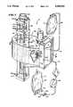
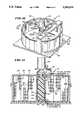
- FIG. 1is a perspective view, with portions broken away and in section of a system for treating fluids using photodynamic therapy that embodies the features of the invention
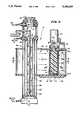
- FIG. 2is a side section view of the system shown in FIG. 1 taken generally along line 2--2 in FIG. 1;
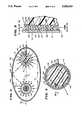
- FIG. 3is a top section view of the system shown in FIG. 1 taken generally along line 3--3 in FIG. 2;
- FIG. 4is a top section view of the treatment chamber associated with the system shown in FIG. taken generally along line 4--4 in FIG. 2;
- FIG. 5is an enlarged side sectional view of the treatment chamber associated with the system shown in FIG. 1 taken generally along line 5--5 in FIG. 4;
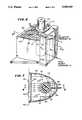
- FIG. 6is a perspective view of another system for treating fluids using photodynamic therapy that embodies the features of the invention.
- FIG. 7is a top sectional view of the system shown in FIG. 6 taken generally along line 7--7 in FIG. 6;
- FIG. 8is a side sectional view of the system shown in FIG. 6 taken generally along line 8--8 in FIG. 7;
- FIG. 9is an elevation view of a portion of the system shown in FIG. 6 taken generally along line 9--9 in FIG. 8;
- FIG. 10is a perspective view of another system for treating fluids using photodynamic therapy that embodies the features of the invention.
- FIG. 11is a side sectional view of the system shown in FIG. 10 taken generally along line 11--11 in FIG. 10;
- FIG. 12is a top sectional view of the system shown in FIG. 10 taken generally along line 12--12 in FIG. 11;
- FIG. 13is an elevation view of a portion of the system shown in FIG. 10 taken generally along line 13--13 in FIG. 12;
- FIG. 14is a perspective view of the treatment chamber and its associated components that the systems shown in FIGS. 1 to 13 incorporate, with the component disassembled as they would be prior to use.
- FIG. 1shows a system 10 for treating a fluid carrying a contaminant that embodies the features of the invention.
- the system 10includes a treatmentdevice 12 that receives the fluid from a source container 14 and conveys the fluid after treatment to a collection container 16.
- the fluid to be treatedcan vary.
- the fluidcomprises a component of whole human blood that is intended to be stored for transfusion. More specifically, the fluid consists of red blood cells suspended in plasma. Typically, a quantity of white blood cells is also present with the red blood cells.
- the fluidcan also include an anticoagulant and, optionally, a storage medium for the blood component. Alternatively, the fluid can consist of platelets suspended in plasma.
- the contaminantcomprises a pathogenic virustypically carried in the blood.
- the contaminantcan consist ofthe hepatitis-B virus; the human immuno-deficiency virus; the Herpes virus;or the influenza virus.
- the fluid in the source container 14includes a photoactive material that has an affinity for the biological contaminant carried by the fluid.
- the photoactive materialis added to the blood contained in the source container 14 after the blood is collected from a donor. The step of addingthe photoactive material will be described in greater detail later.
- the photoactive materialDue to its affinity for the contaminant, the photoactive material becomes bound to the contaminant within the source container 14.
- the photoactive materialis of a type that becomes active by exposure to radiation within a prescribed wavelength range. When activated by radiation, the material eradicates the contaminant.
- the photoactive compoundcomprises a family of light-activateddrugs derived from benzoporphyrin. These derivatives are commonly referred as BPD's. BPD's are commercially available from Quadra Logic Technologies,Inc., Vancouver B.C., Canada.
- BPD'slike other types of hematoporphyrin materials, have an affinity for the cell walls of many viral organisms that are carried in blood. They therefore bind or attach themselves to the biological cell wall of these organisms. When exposed to radiation, BPD's undergo an energy transfer process with oxygen, forming a singlet oxygen. When the singlet oxygen oxidizes, it kills the biological cells to which it has attached. BPD's are described in greater detail in Judy et. al. U.S. Pat. No. 4,878,891.
- the treatment devicepurposefully agitates the fluid while exposing the contaminant to radiation.
- the treatment device 12includes a housing 18 that defines a treatment chamber 20.
- the housing 18has a tubular outer wall 22.
- the housing 18also contains an interior wall 24.
- the inner wall 24takes the shape of a generally cylindrical rotor or spinner 24.
- a relatively narrow arcuate gap 26exists between therotor wall 24 and the interior of the housing wall 22. The arcuate gap 26 forms the confines of the treatment chamber 20.
- the treatment chamber 20has an inner region 25 located along the rotor wall 24 and an outer region23 located along the outer housing wall 22.
- the housing wall 22is made from a material that is essentially transparentto the radiation to thereby pass the radiation into the arcuate gap 26. This is shown by the arrow labeled with the letter R in FIGS. 4 and 5).
- the radiationpasses first into the outer region 23 and then proceeds intothe inner region 25, unless otherwise absorbed or reflected by matter present in the gap 26. Typically, the intensity of the radiation will diminish as it transits from the outer region 23 toward the inner region 25.
- the fluid to be treatedtraverses the gap 26 between an inlet 30 and an outlet 32.
- the inlet 30leads from the source container 14 through inlet tubing 34.
- the outlet 32leads to the collection container 16 through outlet tubing 36.
- a pump 38conveys fluid through the inlet tubing 34.
- Bearings 40carry the spinner 24 for rotation within the housing 18 about an axis 42 that is generally parallel to the direction of fluid flow in the gap 26 (see FIG. 2).
- a drive 44 magnetically coupled to the spinner 24rotates the spinner 24 at a controlled surface velocity
- the rotating spinner 24By rotating the spinner 24 as fluid traverses the gap 26, the flow patternswithin the gap 26 are significantly altered.
- the rotating spinner 24creates secondary fluid flow patterns called vortices 46 within in the gap26 (see FIG. 5).
- the vortices 46spiral in a helical path along the axis ofrotation 42.
- These vortices 46are sometimes referred in the technical literature to as “Taylor Vortices” (see Taylor, “Stability of a Viscous Liquid Contained Between Two Rotating Cylinders", Proc. of the Roval Society, V151 (1935), pp. 289-343).
- the vortices 46continually sweep the material carried by the fluid, including the contaminants to which the photoactive agent are bound (generally designated by numeral 48 in FIG. 5) from the inner region25 of the treatment chamber 20 toward the outer region 23.
- the contaminants 48not only follow an axial path between the inlet 30 and outlet 32 of the gap 26, but the contaminants 48 also follow a radial, spiralling path through the gap 26.
- the vortices 46continually keep the contaminants 48 in circulation near the outer housing wall 22, where the radiation enters the gap 26.
- the vortices 46 shown in FIG. 5can be created in alternate ways.
- the housing 18 itselfcould be rotated about the spinner 24, which itself would remain stationary. This relative rotational movement between the housing 18 and the spinner 24 would create the same type of vortices 46 and lead to the same desirable mixing action.
- the structural and operational relationships that govern the formation of the mixing vortices 46 shown in FIG. 5are generally known.
- the axial value R(known as the axial Reynolds Number) is defined by the equation:
- Vis the average axial velocity of the spinner 24
- dis the width of the gap 26.
- ⁇is the viscosity of the fluid being treated.
- ⁇is the angular velocity of the spinner 24
- ris the radius of the spinner 24
- d and ⁇are as defined above.
- the flowis of a laminar, Couette type.
- a first threshold T valuetypically about 41.3
- the vortices 46will develop without causing turbulence.
- the strength of the vorticeswill increase until a second threshold T value (typically about 400) is reached.
- the system 10will achieve the objectives of the invention under flow conditions (2) and (3).
- the most preferred conditionis (2).
- the size of the gap 26 and the surface velocity of the spinner 24can be varied according to the type of fluid that is to be treated and the flow requirements of the treatment process.
- the gap 26has a width of about 0.02 inch, and a length of about 3.0 inches.
- the spinneris rotated at about 3600 RPM's.
- the treatment device 12includes a radiation chamber 50 that directs radiation into the treatment chamber 20 (that is, into the gap 26).
- the radiation chamber 50can be variously constructed.
- the drawingsshow threealternative constructions.
- the radiation chamber 50includes a single source of radiation 52 and a reflector 54 that envelopes both theradiation source 52 and the treatment device 12.
- the radiation source 52comprises a tubular incandescent bulb 56 having an elongated filament 58.
- a power source(not shown) conveys electricity to the filament 58 to causethe filament 58 to emit radiation.
- the filament materialis selected to emit radiation of a prescribed wavelength or range of wavelengths, according to the fluid that is to be treated.
- filament 58is made of tungsten. This material emits a band of radiation displaying a red color having a wavelength of about 690 nm. Whenoperated at a voltage of about 250 volts (AC), the radiation emitted by thefilament 58 has an intensity of about 1.7 mw/c 2 .
- Red blood cellsare essentially transparent to radiation at this wavelength.
- the BPD'sare not.
- the BPD'sabsorb radiation in this wavelength to become activated.
- the filamentwould be selected to have a wavelength displaying a blue color having peak wavelength of about 425 nm. Platelets are essentially transparent to radiation at this wavelength, but the BPD's are not.
- the incandescent source 52 shown in FIGS. 1 to 3includes first and second chambers 60 and 62 that concentrically surround the bulb 56. Fluids are circulated through these chambers 60 and 62 to cool the radiation source.
- pressurized aircirculates from an inlet 64 through the first chamber 60.
- the airis vented through a chimney 66 from the top of the first chamber 60.
- a secondary cooling liquid like watercirculates from an inlet 68 at the top of the second chamber 62.
- the cooling liquidexits the second chamber 62 through a bottom outlet 70.
- the reflector 54is generally elliptical in shape (as FIG. 3 best shows).
- the elliptical reflector 54has two diametrically spaced focal points positioned 72 and 74 along its major axis 76.
- the filament 58 of the radiation source 52is located at one focal point 72.
- the rotational axis 42 of the spinner 24 within the treatment chamber 20is located at the other focal point 74.
- the entire interior surface of the reflector 54is lined with a material that reflects the radiation emitted by the source 52.
- Gold or like highly reflective materialcan be used to reflect the wavelengths of radiation described above.
- the elliptical reflector 54directs radiation emitted fromthe source uniformly around the exterior of the tubular housing 18 that surrounds the treatment chamber 20. Radiation uniformly fills the gap 26 of the treatment chamber 20 as the spinner 24 rotates to continuously mix the fluid as it traverses the gap 26 (as FIGS. 4 and 5 show).
- the radiation chamber 50includes a plurality of radiation sources (generally designatedby the numeral 78).
- the treatment device 12 associated with this embodimentis the same as the one associated with the embodiment shown in FIGS. 1 to 3(the interior of which in use is also shown in FIGS. 4 and 5).
- each radiation source 78is "discrete,” meaning that each source 78 is a self-contained emitter of radiation that establishes its own zone of radiation. Being discrete, eachsource 78 also is capable of operation to emit a radiation independent of the emission of radiation by the other sources 78.
- each radiation source 78takes the form of aphotodiode.
- various types of photodiodescan be selected, depending upon the fluid to be treated and the characteristics of the photoactive material used.
- T AlGaAstransparent substrate aluminum gallium arsenide material
- Photodiodes of this typeare commercially available from Hewlett-Packard Co. (Product Designation "HLMP-8150 15 Candella").
- These photodiodesemit a band of radiation at a relatively narrow viewing angle of about 4 degrees.
- the prescribed band of radiationhas a relatively precise wavelength displaying a red color having a peak wavelength of about 690 nm.
- the photodiodewould be selected to have a wavelength displaying a blue color having peak wavelenght of about 425 nm.
- each discrete photodiode radiation source 78has a minimum intensity of about 8.0 cd (at 20 mA), a maximum intensity of about 36.0 cd (at 20 mA), and a typical intensity of about 15.0 cd (at 20 mA).
- Each photodiode source 78operates at a low maximum forward voltage of about 2.4 V.
- the discrete radiation sources 78are arranged in a bank 80 (as FIG. 9 best shows).
- the bank 80includes the plurality of discrete sources 78 arranged in rows of about 15 sources each(shown horizontally in FIG. 6). In the illustrated embodiment, the bank 80 includes about 195 discrete radiation sources 78.
- a control element(not shown) operates the discrete radiation sources 78.
- the radiation chamber 50also includes a reflector 82 that surrounds the treatment chamber 20.
- the reflector 82generally conforms to the shape of an ellipse that has been truncated along its minor axis 83 and therefore has but a single focal point 84.
- the bank 80 of radiation sourcesis located across the open end 86 the truncated reflector 82.
- the rotational axis 42 of the treatment chamber 20is located at the closed end 88 along focal point 84.
- the entire interior surface of the reflector 82is lined with a material like gold that reflects the radiation emitted by the source.
- the reflector 82directsradiation emitted from the bank 80 uniformly around the exterior of the tubular housing 18 of the treatment chamber 20. Radiation uniformly fills the gap 26 of the treatment chamber 20 as the spinner 24 rotates to mix the fluid traversing the gap 26.
- the radiation chamber 50includes a plurality of radiation sources that take the form of photodiodes (which are also generally designated by the same numeral 78).
- the discrete radiation sources 78are arranged in individual banks 90.
- the treatment chamber 20does not include a reflector. Instead, the banks 90 of radiation themselves completely surround the treatment chamber20.
- each bank 90includes twenty-four (24) discrete light sources 78.
- the treatmentchamber 20is thereby exposed to some 480 discrete radiation sources 78.
- a control element(not shown) operates the discrete radiation sources 78.
- the enveloping banks 90 of radiation sources 78direct radiation uniformly around the exterior of the tubular housing 18 of the treatment chamber 20. Radiation uniformly fills the gap 26 of the treatment chamber 20 as the spinner 24 is rotated to mix the fluid traversing the gap 26.
- each radiation source 78 shown in the second and third alternative embodimentis discrete, the control element can be configured to operate two or more of the radiation sources at a different wavelength. Alternatively, the control element can be configured to operate two or more of the discrete sources 78 of radiation at substantially the same wavelength.
- each discrete source 78can be varied, as can the intensity of radiation of each source 78.
- the source container 14 and the collection container 16each takes the form of a bag (respectively 94 and 96) made of a flexible inert plastic material, like plasticized medical grade polyvinyl chloride
- the inlet 30 to the treatment device 12includes the length of flexible inert plastic tubing 34.
- the tubing 34terminates in a first connection device 98.
- the tubing 34also includes a conventional inline filter 100 for removing the white blood cells from the fluid prior to entering the treatment device 12.
- the filtration medium usedcan include cotton wool, cellulose acetate, or another synthetic fiber like polyester.
- a length of flexible inert plastic tubing 102also joins the source container 14.
- This tubing 102includes a second connection device 104 thatmates with the first connection device 98 to join the source container 14 to the inlet 30 of treatment device 12 (as FIG. 1 shows).
- connection devices 98 and 104are preferable sterile connection devices like those shown in Granzow et. al. U.S. Pat. Nos. 4,157,723 and 4,265,280, which are incorporated herein by reference.
- the outlet 32 of the treatment device 12also includes the already described tubing 36.
- the end of the tubing 36joins the collection container 16.
- the tubing 36could be normally separated into two lengths, like tubings 34 and 102, each having a sterile connection device to join the collection container 16 to the outlet 32 of the treatment device 12 prior to use.
- an auxiliary container 106holds a solution containing the photoactive material.
- the auxiliary container 106also includes a length of tubing 108 that carries with a third (preferably sterile) connection device 110.
- thesource container 14also includes another length of tubing 112 that carriesa fourth (preferably sterile) connection device 114.
- the photoactive materialcan be conveyed from the auxiliary container 106 into the source container 14 for mixing with the fluid to be treated.
- the joined tubings 108 and 112form a closed, internally sterile path for introducing the photoactive materially into the source container 14.
- the tubing 108can be heat sealed closed downstream of the joined connection devices 110 and 114 (as FIG. 1 shows),and the auxiliary container 106 removed.
- the formed flow pathscomprise a closed, internally sterile path for conveying fluid from the source container 14, through the treatment chamber 20, and into the collection container 16.
- tubing 36After treatment, the tubing 36 can be heat sealed closed and the collectioncontainer 16 removed for storage.
Landscapes
- Health & Medical Sciences (AREA)
- Life Sciences & Earth Sciences (AREA)
- General Health & Medical Sciences (AREA)
- Chemical & Material Sciences (AREA)
- Engineering & Computer Science (AREA)
- Vascular Medicine (AREA)
- Heart & Thoracic Surgery (AREA)
- Animal Behavior & Ethology (AREA)
- Public Health (AREA)
- Veterinary Medicine (AREA)
- Biomedical Technology (AREA)
- Cardiology (AREA)
- Anesthesiology (AREA)
- Hematology (AREA)
- Organic Chemistry (AREA)
- Epidemiology (AREA)
- Medicinal Chemistry (AREA)
- Chemical Kinetics & Catalysis (AREA)
- Toxicology (AREA)
- Bioinformatics & Cheminformatics (AREA)
- Molecular Biology (AREA)
- Genetics & Genomics (AREA)
- Physics & Mathematics (AREA)
- Wood Science & Technology (AREA)
- Zoology (AREA)
- Electromagnetism (AREA)
- Microbiology (AREA)
- Immunology (AREA)
- General Engineering & Computer Science (AREA)
- Biochemistry (AREA)
- Virology (AREA)
- Biotechnology (AREA)
- External Artificial Organs (AREA)
- Apparatus For Disinfection Or Sterilisation (AREA)
- Micro-Organisms Or Cultivation Processes Thereof (AREA)
Abstract
Description
R=Vd/ν,
T.sup.2 =Ω.sup.2 rd.sup.3 /ν.sup.2,
Claims (25)
Priority Applications (1)
| Application Number | Priority Date | Filing Date | Title |
|---|---|---|---|
| US07/991,758US5300019A (en) | 1990-12-20 | 1992-12-17 | Systems and methods for eradicating contaminants using photoactive materials in fluids like blood |
Applications Claiming Priority (2)
| Application Number | Priority Date | Filing Date | Title |
|---|---|---|---|
| US63084090A | 1990-12-20 | 1990-12-20 | |
| US07/991,758US5300019A (en) | 1990-12-20 | 1992-12-17 | Systems and methods for eradicating contaminants using photoactive materials in fluids like blood |
Related Parent Applications (1)
| Application Number | Title | Priority Date | Filing Date |
|---|---|---|---|
| US63084090AContinuation | 1990-12-20 | 1990-12-20 |
Publications (1)
| Publication Number | Publication Date |
|---|---|
| US5300019Atrue US5300019A (en) | 1994-04-05 |
Family
ID=24528764
Family Applications (1)
| Application Number | Title | Priority Date | Filing Date |
|---|---|---|---|
| US07/991,758Expired - LifetimeUS5300019A (en) | 1990-12-20 | 1992-12-17 | Systems and methods for eradicating contaminants using photoactive materials in fluids like blood |
Country Status (7)
| Country | Link |
|---|---|
| US (1) | US5300019A (en) |
| EP (1) | EP0516836B1 (en) |
| JP (1) | JP3051997B2 (en) |
| AU (1) | AU646127B2 (en) |
| CA (1) | CA2075704A1 (en) |
| DE (1) | DE69117940T2 (en) |
| WO (1) | WO1992011058A1 (en) |
Cited By (49)
| Publication number | Priority date | Publication date | Assignee | Title |
|---|---|---|---|---|
| US5702432A (en)* | 1996-10-03 | 1997-12-30 | Light Sciences Limited Partnership | Intracorporeal light treatment of blood |
| WO1998018908A1 (en)* | 1996-10-28 | 1998-05-07 | Baxter International Inc. | Systems and methods for removing viral agents from blood |
| US5804079A (en) | 1991-12-23 | 1998-09-08 | Baxter International Inc. | Systems and methods for reducing the number of leukocytes in cellular products like platelets harvested for therapeutic purposes |
| US5866074A (en)* | 1996-12-20 | 1999-02-02 | Baxter International Inc. | Systems for quantifying the illumination characteristics of vessels such as blood processing containers with respect to light energy |
| US5865785A (en)* | 1996-02-23 | 1999-02-02 | Baxter International Inc. | Systems and methods for on line finishing of cellular blood products like platelets harvested for therapeutic purposes |
| US5922278A (en)* | 1996-11-19 | 1999-07-13 | Baxter International Inc. | Method and apparatus for inactivating contaminants in biological fluid |
| US5935092A (en)* | 1990-12-20 | 1999-08-10 | Baxter International Inc. | Systems and methods for removing free and entrained contaminants in plasma |
| US6168718B1 (en) | 1996-11-08 | 2001-01-02 | Pall Corporation | Method for purifying blood plasma and apparatus suitable therefor |
| US6190609B1 (en) | 1996-11-19 | 2001-02-20 | Baxter International Inc. | Methods and apparatus for inactivating contaminants in biological fluid |
| US6258577B1 (en) | 1998-07-21 | 2001-07-10 | Gambro, Inc. | Method and apparatus for inactivation of biological contaminants using endogenous alloxazine or isoalloxazine photosensitizers |
| US6268120B1 (en) | 1999-10-19 | 2001-07-31 | Gambro, Inc. | Isoalloxazine derivatives to neutralize biological contaminants |
| WO2002004114A3 (en)* | 2000-05-10 | 2002-07-18 | Holl Technologies Company | Electromagnetic wave assisted chemical processing |
| US20020148640A1 (en)* | 2001-04-12 | 2002-10-17 | Holl Technologies Company | Methods of manufacture of electric circuit substrates and components having multiple electric characteristics and substrates and components so manufactured |
| US6471392B1 (en) | 2001-03-07 | 2002-10-29 | Holl Technologies Company | Methods and apparatus for materials processing |
| US20030066624A1 (en)* | 2001-09-13 | 2003-04-10 | Holl Richard A. | Methods and apparatus for transfer of heat energy between a body surface and heat transfer fluid |
| US6565802B1 (en) | 1999-06-03 | 2003-05-20 | Baxter International Inc. | Apparatus, systems and methods for processing and treating a biological fluid with light |
| US6576201B1 (en) | 2000-01-28 | 2003-06-10 | Baxter International Inc. | Device and method for pathogen inactivation of therapeutic fluids with sterilizing radiation |
| US6596230B1 (en) | 2000-01-28 | 2003-07-22 | Baxter International Inc. | Device and method for pathogen inactivation of therapeutic fluids with sterilizing radiation |
| US20030146162A1 (en)* | 1999-06-03 | 2003-08-07 | Metzel Peyton S. | Fluid processing sets and organizers for the same |
| US20030165398A1 (en)* | 1999-06-03 | 2003-09-04 | Waldo Jeffrey M. | Apparatus, systems and methods for processing and treating a biological fluid with light |
| US20030215784A1 (en)* | 1998-07-21 | 2003-11-20 | Dumont Larry Joe | Method and apparatus for inactivation of biological contaminants using photosensitizers |
| US20040013587A1 (en)* | 2002-07-16 | 2004-01-22 | Holl Richard A. | Processes employing multiple successive chemical reaction process steps and apparatus therefore |
| US20040018997A1 (en)* | 1998-07-21 | 2004-01-29 | Heather Reddy | Inactivation of West Nile virus and malaria using photosensitizers |
| US20040052158A1 (en)* | 2002-09-11 | 2004-03-18 | Holl Richard A. | Methods and apparatus for high-shear mixing and reacting of materials |
| US6723999B2 (en) | 1999-07-02 | 2004-04-20 | Holl Technologies Company | Electromagnetic wave assisted chemical processing |
| US20040081956A1 (en)* | 2000-06-02 | 2004-04-29 | Gambro, Inc. | Induction of and maintenance of nucleic acid damage in pathogens using riboflavin and light |
| US6742774B2 (en) | 1999-07-02 | 2004-06-01 | Holl Technologies Company | Process for high shear gas-liquid reactions |
| WO2004019753A3 (en)* | 2002-08-30 | 2004-07-15 | Globalmed Technologies De Colo | Apparatus and method for treating infectious diseases |
| EP1404618A4 (en)* | 2001-05-30 | 2004-08-18 | Hydro Municipal Technologies L | FLUID TREATMENT APPARATUS |
| US6787246B2 (en) | 2001-10-05 | 2004-09-07 | Kreido Laboratories | Manufacture of flat surfaced composites comprising powdered fillers in a polymer matrix |
| US20040188077A1 (en)* | 2002-10-03 | 2004-09-30 | Holl Technologies Company | Apparatus for transfer of heat energy between a body surface and heat transfer fluid |
| US6843961B2 (en) | 2000-06-15 | 2005-01-18 | Gambro, Inc. | Reduction of contaminants in blood and blood products using photosensitizers and peak wavelengths of light |
| US20050033069A1 (en)* | 1999-07-02 | 2005-02-10 | Holl Richard A. | Process for high shear gas-liquid reactions |
| US20050282143A1 (en)* | 1998-07-21 | 2005-12-22 | Gambro, Inc. | Use of visible light at wavelengths of 500 nm and higher to pathogen reduce blood and blood components |
| US7025877B1 (en) | 1999-06-03 | 2006-04-11 | Baxter International Inc. | Processing set for processing and treating a biological fluid |
| US20060159814A1 (en)* | 2002-10-24 | 2006-07-20 | Larry Forney | Systems and methods for disinfection |
| US7094378B1 (en) | 2000-06-15 | 2006-08-22 | Gambro, Inc. | Method and apparatus for inactivation of biological contaminants using photosensitizers |
| US20070098697A1 (en)* | 2000-06-02 | 2007-05-03 | Navigant Biotechnologies, Inc. | Preventing Transfusion Related Complications in a Recipient of a Blood Transfusion |
| US20070099170A1 (en)* | 1998-07-21 | 2007-05-03 | Navigant Biotechnologies, Inc. | Method for treatment and storage of blood and blood products using endogenous alloxazines and acetate |
| US7220747B2 (en) | 1999-07-20 | 2007-05-22 | Gambro, Inc. | Method for preventing damage to or rejuvenating a cellular blood component using mitochondrial enhancer |
| WO2007071018A1 (en)* | 2005-12-19 | 2007-06-28 | Lumen Associates | Apparatus for irradiation of fluid with electromagnetic radiation and method for the same |
| US20070235379A1 (en)* | 2002-05-30 | 2007-10-11 | Hydro Municipal Technologies, Ltd. | Fluid treatment apparatus |
| US20080107636A1 (en)* | 2000-06-02 | 2008-05-08 | Navigant Biotechnologies, Llc | Induction of and Maintenance of Nucleic Acid Damage in Pathogens Using Riboflavin and Light |
| US20080299538A1 (en)* | 2003-02-28 | 2008-12-04 | Caridianbct Biotechnologies, Llc | Pathogen Inactivation of Whole Blood |
| US20090023130A1 (en)* | 2003-02-28 | 2009-01-22 | Caridianbct Biotechnologies, Llc | Prevention of Transfusion Related Acute Lung Injury Using Riboflavin and Light |
| US20090191537A1 (en)* | 2007-12-20 | 2009-07-30 | Veronique Mayaudon | Medium and methods for the storage of platelets |
| RU2466742C2 (en)* | 2005-12-23 | 2012-11-20 | Блутшпендединст Дер Ландесфербэнде Дес Дойчен Ротен Кройцес Нидерзахсен, Захсен-Анхальт, Тюринген, Ольденбург Унд Бремен Ггмбх | Method for pathogen inactivation in donor blood, blood plasma or concentrated erythorocytes in flexible containers by agitation |
| US9044523B2 (en) | 2000-06-15 | 2015-06-02 | Terumo Bct, Inc. | Reduction of contaminants in blood and blood products using photosensitizers and peak wavelengths of light |
| US9402866B2 (en) | 2011-04-07 | 2016-08-02 | Fenwal, Inc. | Automated methods and systems for providing platelet concentrates with reduced residual plasma volumes and storage media for such platelet concentrates |
Families Citing this family (2)
| Publication number | Priority date | Publication date | Assignee | Title |
|---|---|---|---|---|
| ZA919934B (en)* | 1990-12-20 | 1992-09-30 | Baxter Int | Systems and methods for eradicating contaminants using photoactive materials in fluids like blood using discrete sources of radiation |
| CN1973919B (en)* | 2006-12-14 | 2010-06-09 | 山东新华医疗器械股份有限公司 | Cesium-137 radioactive source for blood irradiator |
Citations (33)
| Publication number | Priority date | Publication date | Assignee | Title |
|---|---|---|---|---|
| US2308516A (en)* | 1939-05-01 | 1943-01-19 | Emmet K Knott | Method and means for irradiating blood |
| US4181128A (en)* | 1975-11-28 | 1980-01-01 | Massachusetts Institute Of Technology | Virus inactivation applicator and the like |
| US4321919A (en)* | 1979-12-11 | 1982-03-30 | Leukocyte Research, Inc. | Method and system for externally treating human blood |
| US4398906A (en)* | 1979-12-11 | 1983-08-16 | Frederic A. Bourke, Jr. | Method for externally treating the blood |
| US4402318A (en)* | 1975-11-28 | 1983-09-06 | Swartz Mitchell R | Method for inactivating viruses, bacteria, etc. in vitro and production of vaccines |
| US4428744A (en)* | 1979-12-11 | 1984-01-31 | Frederic A. Bourke, Jr. | Method and system for externally treating the blood |
| US4456512A (en)* | 1982-03-10 | 1984-06-26 | The Dow Chemical Company | Photochemical reactor and method |
| EP0138489A1 (en)* | 1983-09-29 | 1985-04-24 | McNeilab, Inc. | Apparatus and methods for treating cells with radiation |
| US4573962A (en)* | 1984-10-29 | 1986-03-04 | Extracorporeal Medical Specialties, Inc. | Cassette drawer assembly for photoactivation patient treatment system |
| US4612007A (en)* | 1981-06-16 | 1986-09-16 | Edelson Richard Leslie | Method and system for externally treating the blood |
| US4613322A (en)* | 1982-12-08 | 1986-09-23 | Edelson Richard Leslie | Method and system for externally treating the blood |
| US4684521A (en)* | 1982-12-08 | 1987-08-04 | Frederic A. Bourke, Jr. | Method and system for externally treating the blood |
| US4683889A (en)* | 1983-03-29 | 1987-08-04 | Frederic A. Bourke, Jr. | Method and system for externally treating the blood |
| US4705498A (en)* | 1984-10-29 | 1987-11-10 | Mcneilab, Inc. | Disposable temperature probe for photoactivation patient treatment system |
| US4708715A (en)* | 1984-10-29 | 1987-11-24 | Mcneilab, Inc. | Light array assembly for photoactivation patient treatment system |
| US4727027A (en)* | 1983-05-02 | 1988-02-23 | Diamond Scientific Co. | Photochemical decontamination treatment of whole blood or blood components |
| US4737140A (en)* | 1984-10-29 | 1988-04-12 | Mcneilab, Inc. | Irradiation chamber for photoactivation patient treatment system |
| US4769131A (en)* | 1986-05-09 | 1988-09-06 | Pure Water Technologies | Ultraviolet radiation purification system |
| US4775625A (en)* | 1986-11-21 | 1988-10-04 | The Medical College Of Wisconsin, Inc. | Inactivating enveloped viruses with a merocyanine dye |
| US4822335A (en)* | 1986-10-29 | 1989-04-18 | Kureha Kagaku Kogyo Kabushiki Kaisha | Apparatus for treatment of cancer with photodiode |
| US4831268A (en)* | 1985-03-20 | 1989-05-16 | VEB Elektro-und Metallgerate Ilmenau | Method for the physiologically & therapeutically effective irradiation of corporeal venous blood |
| US4838852A (en)* | 1987-03-27 | 1989-06-13 | Therakos, Inc. | Active specific immune suppression |
| US4878891A (en)* | 1987-06-25 | 1989-11-07 | Baylor Research Foundation | Method for eradicating infectious biological contaminants in body tissues |
| US4889129A (en)* | 1982-09-27 | 1989-12-26 | Health Research, Inc. | Apparatus for treatment of tumors |
| US4915638A (en)* | 1988-04-29 | 1990-04-10 | Anthony Domian | Protective enclosure for electrical outlets |
| US4921473A (en)* | 1989-02-02 | 1990-05-01 | Therakos, Inc. | Multicomponent fluid separation and irradiation system |
| US4944883A (en)* | 1987-01-13 | 1990-07-31 | Schoendorfer Donald W | Continuous centrifugation system and method for directly deriving intermediate density material from a suspension |
| US4950225A (en)* | 1988-09-22 | 1990-08-21 | American Immuno Tech, Inc. | Method for extracorporeal blood shear treatment |
| US4983307A (en)* | 1989-08-02 | 1991-01-08 | Serres Naturtek Greenhouses Inc. | Method for sterilizing liquids by ultraviolet radiation |
| US5032241A (en)* | 1987-09-04 | 1991-07-16 | Nutech Energy Systems Inc. | Fluid purification |
| US5069885A (en)* | 1990-04-23 | 1991-12-03 | Ritchie David G | Photocatalytic fluid purification apparatus having helical nontransparent substrate |
| US5078673A (en)* | 1988-11-14 | 1992-01-07 | Neorx Corporation | Selective removal of radiolabeled antibodies |
| EP0525138B1 (en)* | 1990-12-20 | 1998-09-16 | Baxter International Inc. | A device for eradicating contaminants in fluids |
- 1991
- 1991-12-20EPEP92903752Apatent/EP0516836B1/ennot_activeExpired - Lifetime
- 1991-12-20AUAU91651/91Apatent/AU646127B2/ennot_activeCeased
- 1991-12-20CACA002075704Apatent/CA2075704A1/ennot_activeAbandoned
- 1991-12-20JPJP04503416Apatent/JP3051997B2/ennot_activeExpired - Lifetime
- 1991-12-20DEDE69117940Tpatent/DE69117940T2/ennot_activeExpired - Fee Related
- 1991-12-20WOPCT/US1991/009709patent/WO1992011058A1/enactiveIP Right Grant
- 1992
- 1992-12-17USUS07/991,758patent/US5300019A/ennot_activeExpired - Lifetime
Patent Citations (34)
| Publication number | Priority date | Publication date | Assignee | Title |
|---|---|---|---|---|
| US2308516A (en)* | 1939-05-01 | 1943-01-19 | Emmet K Knott | Method and means for irradiating blood |
| US4181128A (en)* | 1975-11-28 | 1980-01-01 | Massachusetts Institute Of Technology | Virus inactivation applicator and the like |
| US4402318A (en)* | 1975-11-28 | 1983-09-06 | Swartz Mitchell R | Method for inactivating viruses, bacteria, etc. in vitro and production of vaccines |
| US4321919A (en)* | 1979-12-11 | 1982-03-30 | Leukocyte Research, Inc. | Method and system for externally treating human blood |
| US4398906A (en)* | 1979-12-11 | 1983-08-16 | Frederic A. Bourke, Jr. | Method for externally treating the blood |
| US4428744A (en)* | 1979-12-11 | 1984-01-31 | Frederic A. Bourke, Jr. | Method and system for externally treating the blood |
| US4612007A (en)* | 1981-06-16 | 1986-09-16 | Edelson Richard Leslie | Method and system for externally treating the blood |
| US4456512A (en)* | 1982-03-10 | 1984-06-26 | The Dow Chemical Company | Photochemical reactor and method |
| US4889129A (en)* | 1982-09-27 | 1989-12-26 | Health Research, Inc. | Apparatus for treatment of tumors |
| US4613322A (en)* | 1982-12-08 | 1986-09-23 | Edelson Richard Leslie | Method and system for externally treating the blood |
| US4684521A (en)* | 1982-12-08 | 1987-08-04 | Frederic A. Bourke, Jr. | Method and system for externally treating the blood |
| US4683889A (en)* | 1983-03-29 | 1987-08-04 | Frederic A. Bourke, Jr. | Method and system for externally treating the blood |
| US4727027A (en)* | 1983-05-02 | 1988-02-23 | Diamond Scientific Co. | Photochemical decontamination treatment of whole blood or blood components |
| EP0138489A1 (en)* | 1983-09-29 | 1985-04-24 | McNeilab, Inc. | Apparatus and methods for treating cells with radiation |
| US4737140A (en)* | 1984-10-29 | 1988-04-12 | Mcneilab, Inc. | Irradiation chamber for photoactivation patient treatment system |
| US4705498A (en)* | 1984-10-29 | 1987-11-10 | Mcneilab, Inc. | Disposable temperature probe for photoactivation patient treatment system |
| US4573962A (en)* | 1984-10-29 | 1986-03-04 | Extracorporeal Medical Specialties, Inc. | Cassette drawer assembly for photoactivation patient treatment system |
| US4708715A (en)* | 1984-10-29 | 1987-11-24 | Mcneilab, Inc. | Light array assembly for photoactivation patient treatment system |
| US4831268A (en)* | 1985-03-20 | 1989-05-16 | VEB Elektro-und Metallgerate Ilmenau | Method for the physiologically & therapeutically effective irradiation of corporeal venous blood |
| US4769131A (en)* | 1986-05-09 | 1988-09-06 | Pure Water Technologies | Ultraviolet radiation purification system |
| US4822335A (en)* | 1986-10-29 | 1989-04-18 | Kureha Kagaku Kogyo Kabushiki Kaisha | Apparatus for treatment of cancer with photodiode |
| US4775625A (en)* | 1986-11-21 | 1988-10-04 | The Medical College Of Wisconsin, Inc. | Inactivating enveloped viruses with a merocyanine dye |
| US4944883A (en)* | 1987-01-13 | 1990-07-31 | Schoendorfer Donald W | Continuous centrifugation system and method for directly deriving intermediate density material from a suspension |
| US4838852A (en)* | 1987-03-27 | 1989-06-13 | Therakos, Inc. | Active specific immune suppression |
| US5030200A (en)* | 1987-06-25 | 1991-07-09 | Baylor Research Foundation | Method for eradicating infectious biological contaminants in body tissues |
| US4878891A (en)* | 1987-06-25 | 1989-11-07 | Baylor Research Foundation | Method for eradicating infectious biological contaminants in body tissues |
| US5032241A (en)* | 1987-09-04 | 1991-07-16 | Nutech Energy Systems Inc. | Fluid purification |
| US4915638A (en)* | 1988-04-29 | 1990-04-10 | Anthony Domian | Protective enclosure for electrical outlets |
| US4950225A (en)* | 1988-09-22 | 1990-08-21 | American Immuno Tech, Inc. | Method for extracorporeal blood shear treatment |
| US5078673A (en)* | 1988-11-14 | 1992-01-07 | Neorx Corporation | Selective removal of radiolabeled antibodies |
| US4921473A (en)* | 1989-02-02 | 1990-05-01 | Therakos, Inc. | Multicomponent fluid separation and irradiation system |
| US4983307A (en)* | 1989-08-02 | 1991-01-08 | Serres Naturtek Greenhouses Inc. | Method for sterilizing liquids by ultraviolet radiation |
| US5069885A (en)* | 1990-04-23 | 1991-12-03 | Ritchie David G | Photocatalytic fluid purification apparatus having helical nontransparent substrate |
| EP0525138B1 (en)* | 1990-12-20 | 1998-09-16 | Baxter International Inc. | A device for eradicating contaminants in fluids |
Non-Patent Citations (2)
| Title |
|---|
| Matthews et al., "Photodynamic Therapy of Viral Contaminants with Potential for Blood Banking Applications", Transfusion, vol. 28,1 1988, pp. 81-83. |
| Matthews et al., Photodynamic Therapy of Viral Contaminants with Potential for Blood Banking Applications , Transfusion, vol. 28,1 1988, pp. 81 83.* |
Cited By (103)
| Publication number | Priority date | Publication date | Assignee | Title |
|---|---|---|---|---|
| US6695805B1 (en) | 1990-12-20 | 2004-02-24 | Baxter International Inc. | Systems and methods for removing free and entrained contaminants in plasma |
| US5935092A (en)* | 1990-12-20 | 1999-08-10 | Baxter International Inc. | Systems and methods for removing free and entrained contaminants in plasma |
| US5804079A (en) | 1991-12-23 | 1998-09-08 | Baxter International Inc. | Systems and methods for reducing the number of leukocytes in cellular products like platelets harvested for therapeutic purposes |
| US6071421A (en) | 1991-12-23 | 2000-06-06 | Baxter International Inc. | Systems and methods for obtaining a platelet suspension having a reduced number of leukocytes |
| US6361692B1 (en) | 1996-02-23 | 2002-03-26 | Baxter International Inc. | On line blood processing system for obtaining for storage a blood suspension having a reduced residual leukocyte population |
| US20030205517A1 (en)* | 1996-02-23 | 2003-11-06 | Baxter International Inc. | Systems and methods for on line finishing of cellular blood products like platelets harvested for therapeutic purposes |
| US5865785A (en)* | 1996-02-23 | 1999-02-02 | Baxter International Inc. | Systems and methods for on line finishing of cellular blood products like platelets harvested for therapeutic purposes |
| US6872307B2 (en) | 1996-02-23 | 2005-03-29 | Baxter International Inc. | Systems and methods for on line finishing of cellular blood products like platelets harvested for therapeutic purposes |
| US20090014395A1 (en)* | 1996-02-23 | 2009-01-15 | Bischof Daniel F | Systems and Methods for On Line Finishing of Cellular Blood Products Like Platelets Harvested for Therapeutic Purposes |
| US6051147A (en)* | 1996-02-23 | 2000-04-18 | Baxter International Inc. | Methods for on line finishing of cellular blood products like platelets harvested for therapeutic purposes |
| US20050139556A1 (en)* | 1996-02-23 | 2005-06-30 | Bischof Daniel F. | Systems and methods for on line finishing of cellular blood products like platelets harvested for therapeutic purposes |
| US5702432A (en)* | 1996-10-03 | 1997-12-30 | Light Sciences Limited Partnership | Intracorporeal light treatment of blood |
| WO1998018908A1 (en)* | 1996-10-28 | 1998-05-07 | Baxter International Inc. | Systems and methods for removing viral agents from blood |
| US6190855B1 (en) | 1996-10-28 | 2001-02-20 | Baxter International Inc. | Systems and methods for removing viral agents from blood |
| US7374870B2 (en) | 1996-10-28 | 2008-05-20 | Fenwal, Inc. | Systems and methods for removing viral agents from blood |
| AU735878B2 (en)* | 1996-10-28 | 2001-07-19 | Fenwal, Inc. | Systems and methods for removing viral agents from blood |
| US20050186553A1 (en)* | 1996-10-28 | 2005-08-25 | Herman Robert E. | Systems and methods for removing viral agents from blood |
| US6855489B1 (en) | 1996-10-28 | 2005-02-15 | Baxter International Inc. | Systems and methods for removing viral agents from blood |
| US6168718B1 (en) | 1996-11-08 | 2001-01-02 | Pall Corporation | Method for purifying blood plasma and apparatus suitable therefor |
| US6190609B1 (en) | 1996-11-19 | 2001-02-20 | Baxter International Inc. | Methods and apparatus for inactivating contaminants in biological fluid |
| EP0885018A4 (en)* | 1996-11-19 | 2001-02-07 | Baxter Int | Method and apparatus for inactivating contaminants in biological fluid |
| US5922278A (en)* | 1996-11-19 | 1999-07-13 | Baxter International Inc. | Method and apparatus for inactivating contaminants in biological fluid |
| EP0900371A4 (en)* | 1996-12-20 | 2000-12-13 | Baxter Int | Systems and methods for quantifying photoreactions in light activated materials |
| US5976884A (en)* | 1996-12-20 | 1999-11-02 | Baxter International Inc. | Methods for quantifying photoreactions in light activated materials |
| US5866074A (en)* | 1996-12-20 | 1999-02-02 | Baxter International Inc. | Systems for quantifying the illumination characteristics of vessels such as blood processing containers with respect to light energy |
| US20050282143A1 (en)* | 1998-07-21 | 2005-12-22 | Gambro, Inc. | Use of visible light at wavelengths of 500 nm and higher to pathogen reduce blood and blood components |
| US7049110B2 (en) | 1998-07-21 | 2006-05-23 | Gambro, Inc. | Inactivation of West Nile virus and malaria using photosensitizers |
| US20070099170A1 (en)* | 1998-07-21 | 2007-05-03 | Navigant Biotechnologies, Inc. | Method for treatment and storage of blood and blood products using endogenous alloxazines and acetate |
| US7498156B2 (en) | 1998-07-21 | 2009-03-03 | Caridianbct Biotechnologies, Llc | Use of visible light at wavelengths of 500 to 550 nm to reduce the number of pathogens in blood and blood components |
| US20030215784A1 (en)* | 1998-07-21 | 2003-11-20 | Dumont Larry Joe | Method and apparatus for inactivation of biological contaminants using photosensitizers |
| US6258577B1 (en) | 1998-07-21 | 2001-07-10 | Gambro, Inc. | Method and apparatus for inactivation of biological contaminants using endogenous alloxazine or isoalloxazine photosensitizers |
| US20040018997A1 (en)* | 1998-07-21 | 2004-01-29 | Heather Reddy | Inactivation of West Nile virus and malaria using photosensitizers |
| US20030146162A1 (en)* | 1999-06-03 | 2003-08-07 | Metzel Peyton S. | Fluid processing sets and organizers for the same |
| US7459695B2 (en) | 1999-06-03 | 2008-12-02 | Fenwal, Inc. | Apparatus, and systems for processing and treating a biological fluid with light |
| US7601298B2 (en) | 1999-06-03 | 2009-10-13 | Fenwal, Inc. | Method for processing and treating a biological fluid with light |
| US7445756B2 (en) | 1999-06-03 | 2008-11-04 | Fenwal, Inc. | Fluid processing sets and organizers for the same |
| US6986867B2 (en) | 1999-06-03 | 2006-01-17 | Baxter International Inc. | Apparatus, systems and methods for processing and treating a biological fluid with light |
| US6565802B1 (en) | 1999-06-03 | 2003-05-20 | Baxter International Inc. | Apparatus, systems and methods for processing and treating a biological fluid with light |
| US20030165398A1 (en)* | 1999-06-03 | 2003-09-04 | Waldo Jeffrey M. | Apparatus, systems and methods for processing and treating a biological fluid with light |
| US7105093B2 (en) | 1999-06-03 | 2006-09-12 | Baxter International Inc. | Processing set and methods for processing and treating a biological fluid |
| US20060197031A1 (en)* | 1999-06-03 | 2006-09-07 | De Gheldere Serge | Processing set and methods for processing and treating a biological fluid |
| US7068361B2 (en) | 1999-06-03 | 2006-06-27 | Baxter International | Apparatus, systems and methods for processing and treating a biological fluid with light |
| US7425304B2 (en) | 1999-06-03 | 2008-09-16 | Fenwal, Inc. | Processing set and methods for processing and treating a biological fluid |
| US7025877B1 (en) | 1999-06-03 | 2006-04-11 | Baxter International Inc. | Processing set for processing and treating a biological fluid |
| US20050258109A1 (en)* | 1999-06-03 | 2005-11-24 | Hanley Kathleen A | Apparatus, systems and methods for processing and treating a biological fluid with light |
| US6994330B2 (en) | 1999-07-02 | 2006-02-07 | Kriedo Laboratories | Process for high shear gas-liquid reactions |
| US20050033069A1 (en)* | 1999-07-02 | 2005-02-10 | Holl Richard A. | Process for high shear gas-liquid reactions |
| US20040222536A1 (en)* | 1999-07-02 | 2004-11-11 | Holl Richard A. | Process for high shear gas-liquid reactions |
| US6742774B2 (en) | 1999-07-02 | 2004-06-01 | Holl Technologies Company | Process for high shear gas-liquid reactions |
| US7538237B2 (en) | 1999-07-02 | 2009-05-26 | Kreido Laboratories | Process for high shear gas-liquid reactions |
| US6723999B2 (en) | 1999-07-02 | 2004-04-20 | Holl Technologies Company | Electromagnetic wave assisted chemical processing |
| US7220747B2 (en) | 1999-07-20 | 2007-05-22 | Gambro, Inc. | Method for preventing damage to or rejuvenating a cellular blood component using mitochondrial enhancer |
| US6828323B2 (en) | 1999-10-19 | 2004-12-07 | Gambro, Inc. | Isoalloxazine derivatives to neutralize biological contaminants |
| US6268120B1 (en) | 1999-10-19 | 2001-07-31 | Gambro, Inc. | Isoalloxazine derivatives to neutralize biological contaminants |
| US6576201B1 (en) | 2000-01-28 | 2003-06-10 | Baxter International Inc. | Device and method for pathogen inactivation of therapeutic fluids with sterilizing radiation |
| US6596230B1 (en) | 2000-01-28 | 2003-07-22 | Baxter International Inc. | Device and method for pathogen inactivation of therapeutic fluids with sterilizing radiation |
| AU2001261444B2 (en)* | 2000-05-10 | 2006-05-25 | Kreido Laboratories | Electromagnetic wave assisted chemical processing |
| WO2002004114A3 (en)* | 2000-05-10 | 2002-07-18 | Holl Technologies Company | Electromagnetic wave assisted chemical processing |
| US7648699B2 (en) | 2000-06-02 | 2010-01-19 | Caridianbct Biotechnologies, Llc | Preventing transfusion related complications in a recipient of a blood transfusion |
| US20100080781A1 (en)* | 2000-06-02 | 2010-04-01 | Caridianbct Biotechnologies, Llc | Preventing Transfusion Related Complications in a Recipient of a Blood Transfusion |
| US20040081956A1 (en)* | 2000-06-02 | 2004-04-29 | Gambro, Inc. | Induction of and maintenance of nucleic acid damage in pathogens using riboflavin and light |
| US7985588B2 (en) | 2000-06-02 | 2011-07-26 | Caridianbct Biotechnologies, Llc | Induction of and maintenance of nucleic acid damage in pathogens using riboflavin and light |
| US7901673B2 (en) | 2000-06-02 | 2011-03-08 | Caridianbct Biotechnologies, Llc | Induction of and maintenance of nucleic acid damage in pathogens using riboflavin and light |
| US20070098697A1 (en)* | 2000-06-02 | 2007-05-03 | Navigant Biotechnologies, Inc. | Preventing Transfusion Related Complications in a Recipient of a Blood Transfusion |
| US7892535B2 (en) | 2000-06-02 | 2011-02-22 | Caridianbct Biotechnologies, Llc | Preventing transfusion related complications in a recipient of a blood transfusion |
| US20080107636A1 (en)* | 2000-06-02 | 2008-05-08 | Navigant Biotechnologies, Llc | Induction of and Maintenance of Nucleic Acid Damage in Pathogens Using Riboflavin and Light |
| US20050112021A1 (en)* | 2000-06-15 | 2005-05-26 | Gambro, Inc. | Reduction of Contaminants In Blood and Blood Products Using Photosensitizers and Peak Wavelengths of Light |
| US7094378B1 (en) | 2000-06-15 | 2006-08-22 | Gambro, Inc. | Method and apparatus for inactivation of biological contaminants using photosensitizers |
| US6843961B2 (en) | 2000-06-15 | 2005-01-18 | Gambro, Inc. | Reduction of contaminants in blood and blood products using photosensitizers and peak wavelengths of light |
| US9044523B2 (en) | 2000-06-15 | 2015-06-02 | Terumo Bct, Inc. | Reduction of contaminants in blood and blood products using photosensitizers and peak wavelengths of light |
| US6471392B1 (en) | 2001-03-07 | 2002-10-29 | Holl Technologies Company | Methods and apparatus for materials processing |
| US6752529B2 (en) | 2001-03-07 | 2004-06-22 | Holl Technologies Company | Methods and apparatus for materials processing |
| US20020148640A1 (en)* | 2001-04-12 | 2002-10-17 | Holl Technologies Company | Methods of manufacture of electric circuit substrates and components having multiple electric characteristics and substrates and components so manufactured |
| US6830806B2 (en) | 2001-04-12 | 2004-12-14 | Kreido Laboratories | Methods of manufacture of electric circuit substrates and components having multiple electric characteristics and substrates and components so manufactured |
| US7238289B2 (en) | 2001-05-30 | 2007-07-03 | Hydro Municipal Technologies, Ltd. | Fluid treatment apparatus |
| US20040251211A1 (en)* | 2001-05-30 | 2004-12-16 | Ralph Suddath | Fluid treatment apparatus |
| EP1404618A4 (en)* | 2001-05-30 | 2004-08-18 | Hydro Municipal Technologies L | FLUID TREATMENT APPARATUS |
| US20030066624A1 (en)* | 2001-09-13 | 2003-04-10 | Holl Richard A. | Methods and apparatus for transfer of heat energy between a body surface and heat transfer fluid |
| US6787246B2 (en) | 2001-10-05 | 2004-09-07 | Kreido Laboratories | Manufacture of flat surfaced composites comprising powdered fillers in a polymer matrix |
| US7473374B2 (en) | 2002-05-30 | 2009-01-06 | Ralph Suddath | Fluid treatment apparatus |
| US20070235379A1 (en)* | 2002-05-30 | 2007-10-11 | Hydro Municipal Technologies, Ltd. | Fluid treatment apparatus |
| US20060245991A1 (en)* | 2002-07-16 | 2006-11-02 | Kreido Laboratories | Processes Employing Multiple Successive Chemical Reaction Process Steps and Apparatus Therefore |
| US20040013587A1 (en)* | 2002-07-16 | 2004-01-22 | Holl Richard A. | Processes employing multiple successive chemical reaction process steps and apparatus therefore |
| US7098360B2 (en) | 2002-07-16 | 2006-08-29 | Kreido Laboratories | Processes employing multiple successive chemical reaction process steps and apparatus therefore |
| US7575728B2 (en) | 2002-07-16 | 2009-08-18 | Kreido Laboratories | Processes employing multiple successive chemical reaction process steps and apparatus therefore |
| WO2004019753A3 (en)* | 2002-08-30 | 2004-07-15 | Globalmed Technologies De Colo | Apparatus and method for treating infectious diseases |
| US20040052158A1 (en)* | 2002-09-11 | 2004-03-18 | Holl Richard A. | Methods and apparatus for high-shear mixing and reacting of materials |
| US7165881B2 (en) | 2002-09-11 | 2007-01-23 | Holl Technologies Corporation | Methods and apparatus for high-shear mixing and reacting of materials |
| US20040188077A1 (en)* | 2002-10-03 | 2004-09-30 | Holl Technologies Company | Apparatus for transfer of heat energy between a body surface and heat transfer fluid |
| US6938687B2 (en) | 2002-10-03 | 2005-09-06 | Holl Technologies Company | Apparatus for transfer of heat energy between a body surface and heat transfer fluid |
| US20060159814A1 (en)* | 2002-10-24 | 2006-07-20 | Larry Forney | Systems and methods for disinfection |
| US7507370B2 (en)* | 2002-10-24 | 2009-03-24 | Georgia Tech Research Corporation | Systems and methods for disinfection |
| US20090023130A1 (en)* | 2003-02-28 | 2009-01-22 | Caridianbct Biotechnologies, Llc | Prevention of Transfusion Related Acute Lung Injury Using Riboflavin and Light |
| US20080299538A1 (en)* | 2003-02-28 | 2008-12-04 | Caridianbct Biotechnologies, Llc | Pathogen Inactivation of Whole Blood |
| WO2007071018A1 (en)* | 2005-12-19 | 2007-06-28 | Lumen Associates | Apparatus for irradiation of fluid with electromagnetic radiation and method for the same |
| US8017921B2 (en) | 2005-12-19 | 2011-09-13 | Lumen Associates, Inc. | Apparatus for irradiation of fluid with electromagnetic radiation and method for the same |
| US20090159813A1 (en)* | 2005-12-19 | 2009-06-25 | Lumen Associates | Apparatus for Irradiation of Fluid with Electromagnetic Radiation and Method for the Same |
| RU2466742C2 (en)* | 2005-12-23 | 2012-11-20 | Блутшпендединст Дер Ландесфербэнде Дес Дойчен Ротен Кройцес Нидерзахсен, Захсен-Анхальт, Тюринген, Ольденбург Унд Бремен Ггмбх | Method for pathogen inactivation in donor blood, blood plasma or concentrated erythorocytes in flexible containers by agitation |
| US20090191537A1 (en)* | 2007-12-20 | 2009-07-30 | Veronique Mayaudon | Medium and methods for the storage of platelets |
| US8835104B2 (en) | 2007-12-20 | 2014-09-16 | Fenwal, Inc. | Medium and methods for the storage of platelets |
| US10358627B2 (en) | 2007-12-20 | 2019-07-23 | Fenwal, Inc. | Medium and methods for the storage of platelets |
| US9402866B2 (en) | 2011-04-07 | 2016-08-02 | Fenwal, Inc. | Automated methods and systems for providing platelet concentrates with reduced residual plasma volumes and storage media for such platelet concentrates |
| US10273456B2 (en) | 2011-04-07 | 2019-04-30 | Fenwal, Inc. | Automated methods and systems for washing platelet concentrates |
Also Published As
| Publication number | Publication date |
|---|---|
| CA2075704A1 (en) | 1992-06-21 |
| WO1992011058A1 (en) | 1992-07-09 |
| AU9165191A (en) | 1992-07-22 |
| JPH05505129A (en) | 1993-08-05 |
| JP3051997B2 (en) | 2000-06-12 |
| EP0516836B1 (en) | 1996-03-13 |
| DE69117940D1 (en) | 1996-04-18 |
| EP0516836A1 (en) | 1992-12-09 |
| AU646127B2 (en) | 1994-02-10 |
| EP0516836A4 (en) | 1993-10-20 |
| DE69117940T2 (en) | 1996-11-21 |
Similar Documents
| Publication | Publication Date | Title |
|---|---|---|
| US5300019A (en) | Systems and methods for eradicating contaminants using photoactive materials in fluids like blood | |
| US5290221A (en) | Systems for eradicating contaminants using photoactive materials in fluids like blood | |
| EP0516839B1 (en) | Systems and methods for simultaneously removing free and entrained contaminants in fluids like blood using photoactive therapy and cellular separation techniques | |
| EP0517899B1 (en) | Systems and methods eradicating contaminants in fluids | |
| US5935092A (en) | Systems and methods for removing free and entrained contaminants in plasma | |
| KR0137934B1 (en) | Blood separation and irradiation system | |
| JP2009178561A (en) | Apparatus and method for irradiating and mixing fluid in container | |
| US7057189B2 (en) | Monochromatic fluid treatment systems |
Legal Events
| Date | Code | Title | Description |
|---|---|---|---|
| FEPP | Fee payment procedure | Free format text:PAYOR NUMBER ASSIGNED (ORIGINAL EVENT CODE: ASPN); ENTITY STATUS OF PATENT OWNER: LARGE ENTITY | |
| STCF | Information on status: patent grant | Free format text:PATENTED CASE | |
| CC | Certificate of correction | ||
| FPAY | Fee payment | Year of fee payment:4 | |
| FPAY | Fee payment | Year of fee payment:8 | |
| FPAY | Fee payment | Year of fee payment:12 | |
| AS | Assignment | Owner name:FENWAL, INC.,ILLINOIS Free format text:PATENT ASSIGNMENT;ASSIGNOR:BAXTER INTERNATIONAL INC.;REEL/FRAME:019129/0001 Effective date:20070301 Owner name:FENWAL, INC., ILLINOIS Free format text:PATENT ASSIGNMENT;ASSIGNOR:BAXTER INTERNATIONAL INC.;REEL/FRAME:019129/0001 Effective date:20070301 | |
| AS | Assignment | Owner name:MORGAN STANLEY & CO. INCORPORATED,NEW YORK Free format text:FIRST-LIEN INTELLECTUAL PROPERTY SECURITY AGREEMENT;ASSIGNORS:FENWAL, INC.;FENWAL HOLDINGS, INC.;REEL/FRAME:019280/0211 Effective date:20070228 Owner name:MORGAN STANLEY & CO. INCORPORATED, NEW YORK Free format text:FIRST-LIEN INTELLECTUAL PROPERTY SECURITY AGREEMENT;ASSIGNORS:FENWAL, INC.;FENWAL HOLDINGS, INC.;REEL/FRAME:019280/0211 Effective date:20070228 | |
| AS | Assignment | Owner name:MORGAN STANLEY & CO. INCORPORATED,NEW YORK Free format text:SECOND-LIEN INTELLECTUAL PROPERTY SECURITY AGREEMENT;ASSIGNORS:FENWAL, INC.;FENWAL HOLDINGS, INC.;REEL/FRAME:019297/0168 Effective date:20070228 Owner name:MORGAN STANLEY & CO. INCORPORATED, NEW YORK Free format text:SECOND-LIEN INTELLECTUAL PROPERTY SECURITY AGREEMENT;ASSIGNORS:FENWAL, INC.;FENWAL HOLDINGS, INC.;REEL/FRAME:019297/0168 Effective date:20070228 | |
| AS | Assignment | Owner name:FENWAL HOLDINGS, INC., ILLINOIS Free format text:RELEASE BY SECURED PARTY;ASSIGNOR:MORGAN STANLEY & CO. LLC;REEL/FRAME:029480/0549 Effective date:20121213 Owner name:FENWAL, INC., ILLINOIS Free format text:RELEASE BY SECURED PARTY;ASSIGNOR:MORGAN STANLEY & CO. LLC;REEL/FRAME:029480/0549 Effective date:20121213 Owner name:FENWAL HOLDINGS, INC., ILLINOIS Free format text:RELEASE BY SECURED PARTY;ASSIGNOR:MORGAN STANLEY & CO. LLC;REEL/FRAME:029480/0597 Effective date:20121213 Owner name:FENWAL, INC., ILLINOIS Free format text:RELEASE BY SECURED PARTY;ASSIGNOR:MORGAN STANLEY & CO. LLC;REEL/FRAME:029480/0597 Effective date:20121213 |