US5299589A - Orthopedic crutch with adjustable hand grip - Google Patents
Orthopedic crutch with adjustable hand gripDownload PDFInfo
- Publication number
- US5299589A US5299589AUS07/881,531US88153192AUS5299589AUS 5299589 AUS5299589 AUS 5299589AUS 88153192 AUS88153192 AUS 88153192AUS 5299589 AUS5299589 AUS 5299589A
- Authority
- US
- United States
- Prior art keywords
- hand grip
- locking member
- vertical supports
- vertical
- detents
- Prior art date
- Legal status (The legal status is an assumption and is not a legal conclusion. Google has not performed a legal analysis and makes no representation as to the accuracy of the status listed.)
- Expired - Lifetime
Links
- 230000000399orthopedic effectEffects0.000titleclaimsabstractdescription21
- 239000004033plasticSubstances0.000claimsdescription3
- 239000000463materialSubstances0.000claimsdescription2
- 239000002991molded plasticSubstances0.000claimsdescription2
- CVRALZAYCYJELZ-UHFFFAOYSA-NO-(4-bromo-2,5-dichlorophenyl) O-methyl phenylphosphonothioateChemical compoundC=1C=CC=CC=1P(=S)(OC)OC1=CC(Cl)=C(Br)C=C1ClCVRALZAYCYJELZ-UHFFFAOYSA-N0.000description1
- 239000004743PolypropyleneSubstances0.000description1
- 238000011065in-situ storageMethods0.000description1
- 230000007246mechanismEffects0.000description1
- 239000007769metal materialSubstances0.000description1
- 238000000034methodMethods0.000description1
- 238000012986modificationMethods0.000description1
- 230000004048modificationEffects0.000description1
- 238000000465mouldingMethods0.000description1
- -1polypropylenePolymers0.000description1
- 229920001155polypropylenePolymers0.000description1
- 238000003825pressingMethods0.000description1
- 230000000717retained effectEffects0.000description1
Images


Classifications
- A—HUMAN NECESSITIES
- A61—MEDICAL OR VETERINARY SCIENCE; HYGIENE
- A61H—PHYSICAL THERAPY APPARATUS, e.g. DEVICES FOR LOCATING OR STIMULATING REFLEX POINTS IN THE BODY; ARTIFICIAL RESPIRATION; MASSAGE; BATHING DEVICES FOR SPECIAL THERAPEUTIC OR HYGIENIC PURPOSES OR SPECIFIC PARTS OF THE BODY
- A61H3/00—Appliances for aiding patients or disabled persons to walk about
- A61H3/02—Crutches
Definitions
- the present inventionrelates to an orthopedic crutch and, more particularly, to an orthopedic crutch with an adjustable hand grip.
- the present inventionprovides an alternative adjustable hand grip for an orthopedic crutch which is also simple and easy to operate by the user without the need of assistance.
- an orthopedic crutchcomprising a pair of spaced apart, generally parallel vertical, preferably tubular, supports rigidly attached to one another, an arm support attached to the upper end of the vertical supports and a vertically adjustable hand grip fixable to the vertical supports.
- each of the vertical supportshas a plurality of spaced apart detents along one longitudinal surface and in another embodiment the vertical supports have a plurality of spaced apart apertures along one longitudinal surface.
- the hand gripcomprises means, such as tubular sleeves, surrounding each vertical support and slidable thereover and a bracket extending between the vertical supports and rigidly connecting the sleeves.
- the sleevesin both embodiments accommodate a locking member extending through an aperture in the sleeve adjacent the vertical support.
- the locking memberhas on a portion of the surface thereof, detent engaging means to engage and be supported within a detent in the vertical support and has on another portion of the surface thereof an area which is configured so as to not engage a detent.
- the locking member, and means to rotate same,are attached to the sleeve to enable the hand grip to be vertically adjusted by disengaging and engaging the detents in vertical supports through rotation of the member so that the hand grip may be placed at an adjustable distance from the arm support to suit the user.
- each sleevehas an aperture adjacent a vertical support extending through the sleeve generally tangentially to the vertical supports.
- the apertureaccommodates a rotatable locking member which is insertable into and through the aperture so that when the locking member is rotated to place the detent engaging surface within a detent in the vertical supports, the hand grip is fixed to the vertical supports. Disengaging the detent by rotation of the locking member enables the hand grip to be relocated by sliding the sleeves up or down along the vertical supports. In this way, the hand grip may be moved vertically to be placed and fixed at an adjustable distance from the arm support of the orthopedic crutch.
- the vertical supportsare provided with apertures on a longitudinal surface, as previously mentioned, and the sleeves are provided with an aperture alignable with apertures in the vertical supports.
- the locking member for locking the sleeve to a vertical supportcomprises a generally U-shaped clamp which surrounds a portion of the sleeve and a pin fixed to the clamp.
- the legs of the U-shaped clampare biased into contact with the sleeve, such as by being slightly undersized with respect to the sleeve's diameter, at least at the ends thereof, and the pin fixed to the clamp is moveable into and out of the apertures in the sleeve and vertical support when they are aligned by moving the clamp toward or away from the vertical supports.
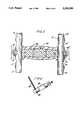
- FIG. 1is a perspective view showing the orthopedic crutch and adjustable hand grip in accordance with one embodiment of the invention; this view shows the locking member in an engaged position with respect to the vertical supports;
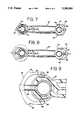
- FIG. 2is a sectional view taken along 2--2 of FIG.;
- FIG. 3is a sectional view similar to FIG. 2 showing the locking member in a disengaged position with respect to the vertical supports;
- FIG. 4is a detail perspective view of the locking member
- FIG. 5is a top view with a partial cut-away showing the locking member in the engaged position
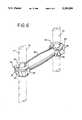
- FIG. 6is a partial perspective view showing the orthopedic crutch with an alternative hand grip embodiment with the hand grip locked in the engaged position;
- FIG. 7is a top view with a partial cut-away in cross section showing the locking member of FIG. 6 engaged;
- FIG. 8is a top view similar to FIG. 7 showing the locking member in the disengaged position
- FIG. 9is an exploded view showing, in detail, the locking member in FIG. 8 disengaged.
- FIGS. 1-5 of the drawingswherein like numerals refer to like parts.
- an orthopedic crutchwhich comprises a pair of generally parallel, vertical tubular supports 10 rigidly attached to one another, anarm support 20 attached to the upper ends of the vertical supports and an adjustable hand grip 30.
- the vertical supports 10are provided with a plurality of spaced apart detents 12 along one longitudinal surface.
- the adjustable hand gripcomprises a pair of tubular sleeves 34, one of which surround each vertical support 10, which are slidable over the vertical supports.
- the sleeves 34are rigidly connected to each other by abracket 32 extending between vertical supports 10.
- Each sleeve 34has an aperture 36 extending through the sleeve adjacent and generally tangentialto a vertical support 10. The aperture forms a passageway for rotatable locking member 42.
- the rotatable locking member 42is insertable throughaperture 36 in sleeve 34 and is configured so as to have a detent engaging surface 44 and a surface 46 which will not engage detents 12 when rotated to face vertical support 10.
- locking member 42comprises abar with a "D" shaped notch, as shown in FIG. 4.
- the locking member 42is rotatable by any suitable rotating means, such as by lever 50 fixed to member 42, in the direction of the arrows shown in FIGS. 2 and 3 into positions to disengage and engage detents 12.
- the hand grip 30When the detent engaging surface 44 is rotated by lever 50 into engagement with vertical support 10 by being positioned within detent 12, the hand grip 30 is in the fixed or locked position with respect to the vertical supports 10.
- the distance between the hand grip 30 and arm support 20is adjusted by simply rotating lever 50 to disengage the locking member from the detent 12 in the vertical support 10, slidably adjusting the location of the hand grip by moving the tubular sleeves 34 upwardly or downwardly as, for example, in the direction of the arrows shown in FIG. 3, to achieve a desired position after which the hand grip may be locked in thatposition by rotating lever 50 so that the detent engaging surface 44 is fixed and locked in positioned within the detent 12.
- the detents 12 shown on the outer surface of the vertical supportsmay be alternately placed along the inside surface.
- a rubber cushion 52may be provided around the bracket 32 to facilitate gripping by the user and the size and configuration of the parts of the hand grip and the vertical supports may be varied.
- Any suitable means to rotate the locking member 42may be used in lieu of lever 50 shown in the drawings and the configurationof the locking member itself may be varied so long as it is configured withone surface to engage the detents in the vertical supports and another surface which does not engage the detents.
- a cam or eccentrically shaped barmay be used for this purpose.
- the locking member 42maybe secured within the aperture 36 of tubular sleeve 30 by means of the screw and washer shown in FIG. 4, however any other suitable means may also be employed.
- FIGS. 6-9An alternative, and presently preferred embodiment of the hand grip is shown in FIGS. 6-9, wherein like numerals also refer to like parts.
- FIG. 6 and FIG. 7the hand grip locking member is shown in the engaged or locked position.
- FIGS. 8 and 9the locking member is shown disengaged.
- the hand grip 60 in this embodimentcomprises a bracket 62 rigidly connecting sleeves 64 which are slidable longitudinally on vertical tubular supports, which are similar to the vertical supports 10 shown in FIG. 1.
- the locking member 80 in this embodimentcomprises a generally U-shaped clamp 82 having legs 84 which surround at least a portion of sleeve 64 and a pin 90 fixed to clamp 82.
- the U-shaped clamp 82is sized to snugly embrace sleeve 64 but is advantageously provided with projections 86 at the end of the legs 84, best seen in FIG. 9, which make firm contact with the external surface of sleeve 64.
- the projections 86are biased into contact with the sleeve 64 by, for example, being slightlyundersized with respect to the outside diameter of the sleeve.
- a slight depression 87may be formed at the external surface of the sleeve or junction of the sleeve and bracket to receive the projection 86 when the clamp is in the engaged position, as shown in FIG. 7, with the locking pin90 inserted through aligned apertures in sleeves 64 and vertical supports 70.
- the hand grip 60is firmly supported between vertical supports 70 and can sustain the weight of the user of the crutch.
- the locking membermay be disengaged from the vertical supports by applying pressure with fingers to finger rests 92to pull or push the clamp 82 outwardly, or to projections 86, so that the locking pin is moved out of the vertical supports 70 into the position shown in FIG. 8, thereby permitting the hand grip to slide longitudinally on the vertical supports 70.
- projections 86will come to rest against stop means 88 provided on the external surface of the sleeve to limit outward movement of the clamp when it is moved from the engaged to the disengaged position.
- the pinWhen the hand grip is in a suitable position for the user, the pin may be movedto the locking position by moving the clamps toward the vertical supports as shown in FIG. 7 so that the pin 90 is moved through the closest alignedapertures in the sleeve 64 and into vertical tubular support 70.
- the sleeve and bracketmay comprise a unitary molded plastic member of suitably rigid plastic material such as polypropylene.
- the pin 90is preferably metallic since it engages the vertical supports which are also generally, and preferably, of metallic material.
- the apertures in the vertical supportsmay be either drilled or punched into a longitudinal surface thereof.
- the pin 90is fixed to the clamp82 such as by being fixed in situ during the molding of the plastic clamp, or the pin can be threaded to the clamp or retained by a nut or lock washer.
Landscapes
- Health & Medical Sciences (AREA)
- Epidemiology (AREA)
- Pain & Pain Management (AREA)
- Physical Education & Sports Medicine (AREA)
- Rehabilitation Therapy (AREA)
- Life Sciences & Earth Sciences (AREA)
- Animal Behavior & Ethology (AREA)
- General Health & Medical Sciences (AREA)
- Public Health (AREA)
- Veterinary Medicine (AREA)
- Rehabilitation Tools (AREA)
Abstract
Description
Claims (6)
Priority Applications (5)
| Application Number | Priority Date | Filing Date | Title |
|---|---|---|---|
| US07/881,531US5299589A (en) | 1992-05-12 | 1992-05-12 | Orthopedic crutch with adjustable hand grip |
| US08/001,830US5291910A (en) | 1992-05-12 | 1993-01-08 | Adjustable hand grip for orthopedic crutch |
| CA002095947ACA2095947C (en) | 1992-05-12 | 1993-05-11 | Adjustable hand grip for orthopedic crutch |
| JP5110669AJPH0686795A (en) | 1992-05-12 | 1993-05-12 | Adjustable grip part for orthopaedic crutch |
| US08/144,183US5381813A (en) | 1992-05-12 | 1993-10-27 | Adjustable hand grip for orthopedic crutch |
Applications Claiming Priority (1)
| Application Number | Priority Date | Filing Date | Title |
|---|---|---|---|
| US07/881,531US5299589A (en) | 1992-05-12 | 1992-05-12 | Orthopedic crutch with adjustable hand grip |
Related Child Applications (1)
| Application Number | Title | Priority Date | Filing Date |
|---|---|---|---|
| US08/001,830Continuation-In-PartUS5291910A (en) | 1992-05-12 | 1993-01-08 | Adjustable hand grip for orthopedic crutch |
Publications (1)
| Publication Number | Publication Date |
|---|---|
| US5299589Atrue US5299589A (en) | 1994-04-05 |
Family
ID=25378666
Family Applications (1)
| Application Number | Title | Priority Date | Filing Date |
|---|---|---|---|
| US07/881,531Expired - LifetimeUS5299589A (en) | 1992-05-12 | 1992-05-12 | Orthopedic crutch with adjustable hand grip |
Country Status (2)
| Country | Link |
|---|---|
| US (1) | US5299589A (en) |
| CA (1) | CA2095947C (en) |
Cited By (14)
| Publication number | Priority date | Publication date | Assignee | Title |
|---|---|---|---|---|
| US5402811A (en)* | 1994-08-19 | 1995-04-04 | Keep-Young Industry Co., Ltd. | Telescopic and foldable crutch structure |
| US5564451A (en)* | 1995-02-21 | 1996-10-15 | Hagberg; Nils G. | Forearm crutch |
| US5671765A (en)* | 1995-02-21 | 1997-09-30 | Hagberg, Jr.; Nils G. | Forearm crutch |
| US20020189658A1 (en)* | 2001-06-18 | 2002-12-19 | Shia-Kan Wang | Crutch |
| US6802326B2 (en)* | 2001-05-14 | 2004-10-12 | Fuji Pharmaceuticals Ltd. | Crutch with height-adjustable grip |
| US20060118154A1 (en)* | 2004-11-24 | 2006-06-08 | Medline Industries, Inc. | Crutches that convert into canes and methods for conversion of same |
| US20060195170A1 (en)* | 2002-05-23 | 2006-08-31 | Ehud Cohen | Electrode assembly for nerve control |
| US20070021799A1 (en)* | 2000-09-27 | 2007-01-25 | Cvrx, Inc. | Automatic baroreflex modulation based on cardiac activity |
| US20080283104A1 (en)* | 2007-05-18 | 2008-11-20 | Kuan-Jen Weng | Reinforced axillary crutch with adjustable handgrip |
| US9050239B1 (en)* | 2014-04-01 | 2015-06-09 | Green Young Industrial Co., Ltd. | Crutch |
| USD770162S1 (en)* | 2014-10-23 | 2016-11-01 | Medline Industries, Inc. | Crutch grip |
| US10278886B2 (en)* | 2014-10-23 | 2019-05-07 | Medline Industries, Inc. | Crutch grip, crutch grip assembly, and corresponding methods |
| USD945256S1 (en) | 2019-11-25 | 2022-03-08 | Medline Industries, Lp | Clip with post and finger tabs |
| USD1007137S1 (en)* | 2017-11-08 | 2023-12-12 | Aligned As Designed, LLC | Crutch |
Citations (22)
| Publication number | Priority date | Publication date | Assignee | Title |
|---|---|---|---|---|
| DE187555C (en)* | ||||
| US596203A (en)* | 1897-12-28 | Crutch | ||
| US705741A (en)* | 1901-11-04 | 1902-07-29 | Frank G Snook | Adjustable crutch. |
| US904481A (en)* | 1908-02-27 | 1908-11-17 | Charles N Prouty | Crutch. |
| US1225364A (en)* | 1916-12-19 | 1917-05-08 | Peter W Sanders | Crutch. |
| US1253117A (en)* | 1917-03-23 | 1918-01-08 | Austin R Allen | Crutch. |
| US2208796A (en)* | 1938-05-20 | 1940-07-23 | Standard Computing Scale Compa | Locking device for food chopper bowls |
| US2429409A (en)* | 1943-05-10 | 1947-10-21 | Guy G Eidman | Crutch |
| GB702634A (en)* | 1952-02-20 | 1954-01-20 | Dudley Austic Layton | Improvements in orthopaedic crutches |
| US2669244A (en)* | 1952-04-08 | 1954-02-16 | Charles C Greene | Crutch with adjustable handgrip |
| US2793647A (en)* | 1954-07-27 | 1957-05-28 | Harold T Urie | Adjustable crutch |
| US2825591A (en)* | 1953-08-18 | 1958-03-04 | Elly Estie | Clamps for use in scaffolding and like structures |
| US3277767A (en)* | 1964-08-03 | 1966-10-11 | Monogram Ind Inc | Quick release pin with rigidly attached handle |
| US3335735A (en)* | 1965-09-14 | 1967-08-15 | Elizabeth L Colegrove | Crutch |
| US3710807A (en)* | 1971-11-18 | 1973-01-16 | C Ferry | Crutches |
| US3768495A (en)* | 1971-06-11 | 1973-10-30 | A Smith | Crutch with adjustable handgrip |
| US4054396A (en)* | 1976-08-24 | 1977-10-18 | Cassidy Charles E | Template holder |
| US4596484A (en)* | 1984-10-05 | 1986-06-24 | Velbon International Corporation | Lock for telescoping tubular support |
| US4753259A (en)* | 1987-04-03 | 1988-06-28 | Hansen Ries B | Adjustable folding walking aid |
| US4786022A (en)* | 1987-05-22 | 1988-11-22 | Grieshaber Manufacturing Co. | Attaching device |
| US4809995A (en)* | 1987-12-17 | 1989-03-07 | Kennametal Inc. | Quick-change mechanism with eccentric lock |
| US4979533A (en)* | 1989-01-17 | 1990-12-25 | Triad Technologies, Inc. | Adjustable orthopedic crutch |
- 1992
- 1992-05-12USUS07/881,531patent/US5299589A/ennot_activeExpired - Lifetime
- 1993
- 1993-05-11CACA002095947Apatent/CA2095947C/ennot_activeExpired - Fee Related
Patent Citations (22)
| Publication number | Priority date | Publication date | Assignee | Title |
|---|---|---|---|---|
| US596203A (en)* | 1897-12-28 | Crutch | ||
| DE187555C (en)* | ||||
| US705741A (en)* | 1901-11-04 | 1902-07-29 | Frank G Snook | Adjustable crutch. |
| US904481A (en)* | 1908-02-27 | 1908-11-17 | Charles N Prouty | Crutch. |
| US1225364A (en)* | 1916-12-19 | 1917-05-08 | Peter W Sanders | Crutch. |
| US1253117A (en)* | 1917-03-23 | 1918-01-08 | Austin R Allen | Crutch. |
| US2208796A (en)* | 1938-05-20 | 1940-07-23 | Standard Computing Scale Compa | Locking device for food chopper bowls |
| US2429409A (en)* | 1943-05-10 | 1947-10-21 | Guy G Eidman | Crutch |
| GB702634A (en)* | 1952-02-20 | 1954-01-20 | Dudley Austic Layton | Improvements in orthopaedic crutches |
| US2669244A (en)* | 1952-04-08 | 1954-02-16 | Charles C Greene | Crutch with adjustable handgrip |
| US2825591A (en)* | 1953-08-18 | 1958-03-04 | Elly Estie | Clamps for use in scaffolding and like structures |
| US2793647A (en)* | 1954-07-27 | 1957-05-28 | Harold T Urie | Adjustable crutch |
| US3277767A (en)* | 1964-08-03 | 1966-10-11 | Monogram Ind Inc | Quick release pin with rigidly attached handle |
| US3335735A (en)* | 1965-09-14 | 1967-08-15 | Elizabeth L Colegrove | Crutch |
| US3768495A (en)* | 1971-06-11 | 1973-10-30 | A Smith | Crutch with adjustable handgrip |
| US3710807A (en)* | 1971-11-18 | 1973-01-16 | C Ferry | Crutches |
| US4054396A (en)* | 1976-08-24 | 1977-10-18 | Cassidy Charles E | Template holder |
| US4596484A (en)* | 1984-10-05 | 1986-06-24 | Velbon International Corporation | Lock for telescoping tubular support |
| US4753259A (en)* | 1987-04-03 | 1988-06-28 | Hansen Ries B | Adjustable folding walking aid |
| US4786022A (en)* | 1987-05-22 | 1988-11-22 | Grieshaber Manufacturing Co. | Attaching device |
| US4809995A (en)* | 1987-12-17 | 1989-03-07 | Kennametal Inc. | Quick-change mechanism with eccentric lock |
| US4979533A (en)* | 1989-01-17 | 1990-12-25 | Triad Technologies, Inc. | Adjustable orthopedic crutch |
Non-Patent Citations (2)
| Title |
|---|
| A portion of an undated brochure showing elbow crutches manufactured by Gauthier Villot and believed to be sold by Walk Easy, Inc.* |
| A portion of an undated brochure showing elbow crutches manufactured by Gauthier-Villot and believed to be sold by Walk Easy, Inc. |
Cited By (14)
| Publication number | Priority date | Publication date | Assignee | Title |
|---|---|---|---|---|
| US5402811A (en)* | 1994-08-19 | 1995-04-04 | Keep-Young Industry Co., Ltd. | Telescopic and foldable crutch structure |
| US5564451A (en)* | 1995-02-21 | 1996-10-15 | Hagberg; Nils G. | Forearm crutch |
| US5671765A (en)* | 1995-02-21 | 1997-09-30 | Hagberg, Jr.; Nils G. | Forearm crutch |
| US20070021799A1 (en)* | 2000-09-27 | 2007-01-25 | Cvrx, Inc. | Automatic baroreflex modulation based on cardiac activity |
| US6802326B2 (en)* | 2001-05-14 | 2004-10-12 | Fuji Pharmaceuticals Ltd. | Crutch with height-adjustable grip |
| US20020189658A1 (en)* | 2001-06-18 | 2002-12-19 | Shia-Kan Wang | Crutch |
| US20060195170A1 (en)* | 2002-05-23 | 2006-08-31 | Ehud Cohen | Electrode assembly for nerve control |
| US20060118154A1 (en)* | 2004-11-24 | 2006-06-08 | Medline Industries, Inc. | Crutches that convert into canes and methods for conversion of same |
| US20080283104A1 (en)* | 2007-05-18 | 2008-11-20 | Kuan-Jen Weng | Reinforced axillary crutch with adjustable handgrip |
| US9050239B1 (en)* | 2014-04-01 | 2015-06-09 | Green Young Industrial Co., Ltd. | Crutch |
| USD770162S1 (en)* | 2014-10-23 | 2016-11-01 | Medline Industries, Inc. | Crutch grip |
| US10278886B2 (en)* | 2014-10-23 | 2019-05-07 | Medline Industries, Inc. | Crutch grip, crutch grip assembly, and corresponding methods |
| USD1007137S1 (en)* | 2017-11-08 | 2023-12-12 | Aligned As Designed, LLC | Crutch |
| USD945256S1 (en) | 2019-11-25 | 2022-03-08 | Medline Industries, Lp | Clip with post and finger tabs |
Also Published As
| Publication number | Publication date |
|---|---|
| CA2095947A1 (en) | 1993-11-13 |
| CA2095947C (en) | 1996-07-30 |
Similar Documents
| Publication | Publication Date | Title |
|---|---|---|
| US5299589A (en) | Orthopedic crutch with adjustable hand grip | |
| US5381813A (en) | Adjustable hand grip for orthopedic crutch | |
| US5775352A (en) | Cam lock assembly for adjustable cane | |
| US6138301A (en) | Bed transfer device | |
| US6079894A (en) | Integral snap button and anti-rattle member | |
| US7753610B2 (en) | Adjustment assembly | |
| US5331720A (en) | Manual implement handle attachment | |
| US4215839A (en) | Tripod | |
| US4895330A (en) | Cane holder | |
| US3224800A (en) | Adjustable supporting leg | |
| US7823230B2 (en) | Bath tub rail | |
| US6283484B1 (en) | Braking device | |
| US4977914A (en) | Slip resistent apparatus for canes, crutches and walkers | |
| US4884587A (en) | Auxiliary cane or crutch device for helping to lift legs or feet or foot | |
| US6880845B1 (en) | Wheelchair footrest retractor | |
| US5651755A (en) | Hand-held exerciser | |
| US20060226315A1 (en) | Walking aid retention device | |
| US5454540A (en) | Suction cup release mechanism | |
| WO1990007919A1 (en) | Adjustable orthopedic crutch | |
| US5352057A (en) | Adjustment tool for telescoping members | |
| US9987189B2 (en) | Mobility assistance device | |
| US20060230540A1 (en) | Patient hand support aid for bed | |
| US5255696A (en) | Walker release button | |
| EP1962652B1 (en) | Aid for taking off stockings | |
| US11376174B2 (en) | Wheelchair accessory apparatus |
Legal Events
| Date | Code | Title | Description |
|---|---|---|---|
| AS | Assignment | Owner name:GUARDIAN PRODUCTS, INC., A CORP. OF CA, CALIFORNIA Free format text:ASSIGNMENT OF ASSIGNORS INTEREST.;ASSIGNORS:BUI, CUONG;SCHULTZ, JIM R.;REEL/FRAME:006226/0553 Effective date:19920810 | |
| AS | Assignment | Owner name:GUARDIAN PRODUCTS INC., CALIFORNIA Free format text:ASSIGNMENT OF ASSIGNORS INTEREST.;ASSIGNOR:ZATULOVSKY, LEO;REEL/FRAME:006492/0072 Effective date:19930407 | |
| STCF | Information on status: patent grant | Free format text:PATENTED CASE | |
| FEPP | Fee payment procedure | Free format text:PAYOR NUMBER ASSIGNED (ORIGINAL EVENT CODE: ASPN); ENTITY STATUS OF PATENT OWNER: LARGE ENTITY | |
| FPAY | Fee payment | Year of fee payment:4 | |
| FEPP | Fee payment procedure | Free format text:PAYOR NUMBER ASSIGNED (ORIGINAL EVENT CODE: ASPN); ENTITY STATUS OF PATENT OWNER: LARGE ENTITY Free format text:PAYER NUMBER DE-ASSIGNED (ORIGINAL EVENT CODE: RMPN); ENTITY STATUS OF PATENT OWNER: LARGE ENTITY | |
| AS | Assignment | Owner name:SUNRISE MEDICAL HHG INC., COLORADO Free format text:MERGER;ASSIGNOR:GUARDIAN PRODUCTS, INC.;REEL/FRAME:009005/0055 Effective date:19970627 | |
| FEPP | Fee payment procedure | Free format text:PAYER NUMBER DE-ASSIGNED (ORIGINAL EVENT CODE: RMPN); ENTITY STATUS OF PATENT OWNER: LARGE ENTITY Free format text:PAYOR NUMBER ASSIGNED (ORIGINAL EVENT CODE: ASPN); ENTITY STATUS OF PATENT OWNER: LARGE ENTITY | |
| AS | Assignment | Owner name:BANKERS TRUST COMPANY, NEW YORK Free format text:SECURITY INTEREST;ASSIGNOR:SUNRISE MEDICAL HHG INC.;REEL/FRAME:011506/0787 Effective date:20001213 | |
| FPAY | Fee payment | Year of fee payment:8 | |
| AS | Assignment | Owner name:SUNRISE MEDICAL HHG INC, COLORADO Free format text:PATENT RELEASE;ASSIGNOR:DEUTSCHE BANK TRUST COMPANY AMERICAS;REEL/FRAME:014683/0526 Effective date:20040512 | |
| AS | Assignment | Owner name:DEUTSCHE BANK TRUST COMPANY AMERICAS, NEW YORK Free format text:SECURITY AGREEMENT;ASSIGNOR:SUNRISE MEDICAL HHG INC.;REEL/FRAME:015302/0454 Effective date:20040513 | |
| FPAY | Fee payment | Year of fee payment:12 | |
| AS | Assignment | Owner name:SUNRISE MEDICAL HHG INC., COLORADO Free format text:RELEASE BY SECURED PARTY;ASSIGNOR:DEUTSCHE BANK TRUST COMPANY AMERICAS;REEL/FRAME:035135/0273 Effective date:20121130 |