US5297443A - Flexible positioning appendage - Google Patents
Flexible positioning appendageDownload PDFInfo
- Publication number
- US5297443A US5297443AUS07/909,960US90996092AUS5297443AUS 5297443 AUS5297443 AUS 5297443AUS 90996092 AUS90996092 AUS 90996092AUS 5297443 AUS5297443 AUS 5297443A
- Authority
- US
- United States
- Prior art keywords
- segments
- appendage
- control line
- flexible positioning
- control lines
- Prior art date
- Legal status (The legal status is an assumption and is not a legal conclusion. Google has not performed a legal analysis and makes no representation as to the accuracy of the status listed.)
- Expired - Lifetime
Links
- 230000008878couplingEffects0.000claimsabstractdescription37
- 238000010168coupling processMethods0.000claimsabstractdescription37
- 238000005859coupling reactionMethods0.000claimsabstractdescription37
- 238000005452bendingMethods0.000claimsdescription29
- 239000000463materialSubstances0.000claimsdescription9
- 238000004382pottingMethods0.000claimsdescription3
- 125000006850spacer groupChemical group0.000claimsdescription3
- 230000000284resting effectEffects0.000claims1
- 210000001503jointAnatomy0.000description7
- 241001465754MetazoaSpecies0.000description4
- 230000005484gravityEffects0.000description4
- 239000004033plasticSubstances0.000description4
- 229920003023plasticPolymers0.000description4
- 241000270295SerpentesSpecies0.000description3
- 208000027418Wounds and injuryDiseases0.000description3
- 239000012530fluidSubstances0.000description3
- 230000033001locomotionEffects0.000description3
- 241000406668Loxodonta cyclotisSpecies0.000description2
- 239000007921spraySubstances0.000description2
- 210000002105tongueAnatomy0.000description2
- 241000251468ActinopterygiiSpecies0.000description1
- 241000238413OctopusSpecies0.000description1
- 239000000853adhesiveSubstances0.000description1
- 230000001070adhesive effectEffects0.000description1
- 239000011324beadSubstances0.000description1
- 210000000988bone and boneAnatomy0.000description1
- 230000000295complement effectEffects0.000description1
- 150000001875compoundsChemical class0.000description1
- 230000008602contractionEffects0.000description1
- 230000006378damageEffects0.000description1
- 238000006073displacement reactionMethods0.000description1
- 229920001971elastomerPolymers0.000description1
- 210000002310elbow jointAnatomy0.000description1
- 210000004553finger phalanxAnatomy0.000description1
- 229920002457flexible plasticPolymers0.000description1
- 239000006260foamSubstances0.000description1
- 230000006870functionEffects0.000description1
- 208000014674injuryDiseases0.000description1
- 210000001847jawAnatomy0.000description1
- 210000004373mandibleAnatomy0.000description1
- 230000013011matingEffects0.000description1
- 230000007246mechanismEffects0.000description1
- 239000002184metalSubstances0.000description1
- 238000000034methodMethods0.000description1
- 230000003278mimic effectEffects0.000description1
- 238000000465mouldingMethods0.000description1
- 238000010422paintingMethods0.000description1
- 239000004417polycarbonateSubstances0.000description1
- 229920000515polycarbonatePolymers0.000description1
- 229920002635polyurethanePolymers0.000description1
- 239000004814polyurethaneSubstances0.000description1
- 238000011084recoveryMethods0.000description1
- 238000009877renderingMethods0.000description1
- 239000012858resilient materialSubstances0.000description1
- 238000004904shorteningMethods0.000description1
- 238000004088simulationMethods0.000description1
- 239000007787solidSubstances0.000description1
- 238000007592spray painting techniqueMethods0.000description1
- 238000010408sweepingMethods0.000description1
- 238000003466weldingMethods0.000description1
Images


Classifications
- B—PERFORMING OPERATIONS; TRANSPORTING
- B25—HAND TOOLS; PORTABLE POWER-DRIVEN TOOLS; MANIPULATORS
- B25J—MANIPULATORS; CHAMBERS PROVIDED WITH MANIPULATION DEVICES
- B25J18/00—Arms
- B25J18/06—Arms flexible
- A—HUMAN NECESSITIES
- A61—MEDICAL OR VETERINARY SCIENCE; HYGIENE
- A61B—DIAGNOSIS; SURGERY; IDENTIFICATION
- A61B34/00—Computer-aided surgery; Manipulators or robots specially adapted for use in surgery
- A61B34/70—Manipulators specially adapted for use in surgery
- A—HUMAN NECESSITIES
- A61—MEDICAL OR VETERINARY SCIENCE; HYGIENE
- A61B—DIAGNOSIS; SURGERY; IDENTIFICATION
- A61B34/00—Computer-aided surgery; Manipulators or robots specially adapted for use in surgery
- A61B34/70—Manipulators specially adapted for use in surgery
- A61B34/71—Manipulators operated by drive cable mechanisms
- B—PERFORMING OPERATIONS; TRANSPORTING
- B05—SPRAYING OR ATOMISING IN GENERAL; APPLYING FLUENT MATERIALS TO SURFACES, IN GENERAL
- B05B—SPRAYING APPARATUS; ATOMISING APPARATUS; NOZZLES
- B05B15/00—Details of spraying plant or spraying apparatus not otherwise provided for; Accessories
- B05B15/60—Arrangements for mounting, supporting or holding spraying apparatus
- B05B15/65—Mounting arrangements for fluid connection of the spraying apparatus or its outlets to flow conduits
- B05B15/652—Mounting arrangements for fluid connection of the spraying apparatus or its outlets to flow conduits whereby the jet can be oriented
- B—PERFORMING OPERATIONS; TRANSPORTING
- B25—HAND TOOLS; PORTABLE POWER-DRIVEN TOOLS; MANIPULATORS
- B25J—MANIPULATORS; CHAMBERS PROVIDED WITH MANIPULATION DEVICES
- B25J15/00—Gripping heads and other end effectors
- B25J15/08—Gripping heads and other end effectors having finger members
- B25J15/12—Gripping heads and other end effectors having finger members with flexible finger members
- A—HUMAN NECESSITIES
- A61—MEDICAL OR VETERINARY SCIENCE; HYGIENE
- A61B—DIAGNOSIS; SURGERY; IDENTIFICATION
- A61B17/00—Surgical instruments, devices or methods
- A61B17/00234—Surgical instruments, devices or methods for minimally invasive surgery
- A61B2017/00292—Surgical instruments, devices or methods for minimally invasive surgery mounted on or guided by flexible, e.g. catheter-like, means
- A61B2017/003—Steerable
- A61B2017/00318—Steering mechanisms
- A61B2017/00323—Cables or rods
- A—HUMAN NECESSITIES
- A61—MEDICAL OR VETERINARY SCIENCE; HYGIENE
- A61B—DIAGNOSIS; SURGERY; IDENTIFICATION
- A61B17/00—Surgical instruments, devices or methods
- A61B17/28—Surgical forceps
- A61B17/29—Forceps for use in minimally invasive surgery
- A61B2017/2901—Details of shaft
- A61B2017/2905—Details of shaft flexible
- A—HUMAN NECESSITIES
- A61—MEDICAL OR VETERINARY SCIENCE; HYGIENE
- A61B—DIAGNOSIS; SURGERY; IDENTIFICATION
- A61B17/00—Surgical instruments, devices or methods
- A61B17/28—Surgical forceps
- A61B17/29—Forceps for use in minimally invasive surgery
- A61B2017/2926—Details of heads or jaws
- A61B2017/2927—Details of heads or jaws the angular position of the head being adjustable with respect to the shaft
- A—HUMAN NECESSITIES
- A61—MEDICAL OR VETERINARY SCIENCE; HYGIENE
- A61B—DIAGNOSIS; SURGERY; IDENTIFICATION
- A61B34/00—Computer-aided surgery; Manipulators or robots specially adapted for use in surgery
- A61B34/30—Surgical robots
- A61B2034/301—Surgical robots for introducing or steering flexible instruments inserted into the body, e.g. catheters or endoscopes
- A—HUMAN NECESSITIES
- A61—MEDICAL OR VETERINARY SCIENCE; HYGIENE
- A61B—DIAGNOSIS; SURGERY; IDENTIFICATION
- A61B34/00—Computer-aided surgery; Manipulators or robots specially adapted for use in surgery
- A61B34/70—Manipulators specially adapted for use in surgery
- A61B34/74—Manipulators with manual electric input means
- A61B2034/742—Joysticks
- A—HUMAN NECESSITIES
- A61—MEDICAL OR VETERINARY SCIENCE; HYGIENE
- A61B—DIAGNOSIS; SURGERY; IDENTIFICATION
- A61B34/00—Computer-aided surgery; Manipulators or robots specially adapted for use in surgery
- A61B34/30—Surgical robots
- Y—GENERAL TAGGING OF NEW TECHNOLOGICAL DEVELOPMENTS; GENERAL TAGGING OF CROSS-SECTIONAL TECHNOLOGIES SPANNING OVER SEVERAL SECTIONS OF THE IPC; TECHNICAL SUBJECTS COVERED BY FORMER USPC CROSS-REFERENCE ART COLLECTIONS [XRACs] AND DIGESTS
- Y10—TECHNICAL SUBJECTS COVERED BY FORMER USPC
- Y10T—TECHNICAL SUBJECTS COVERED BY FORMER US CLASSIFICATION
- Y10T74/00—Machine element or mechanism
- Y10T74/20—Control lever and linkage systems
- Y10T74/20207—Multiple controlling elements for single controlled element
- Y10T74/20305—Robotic arm
- Y10T74/20323—Robotic arm including flaccid drive element
Definitions
- This inventionrelates to the field of elongated flexible structures having longitudinally operable tension or extension mechanisms spaced laterally of a central axis such that the flexible structures can be moved into a curved configuration by applying relatively more longitudinal tension or extension on one side of the axis than the other. More particularly, the invention concerns such a structure wherein a plurality of rigid segments, which are preferably coupled by closed helical springs that space flanged ends of the segments, are provided with control lines for exerting tension between a proximal end of the structure and at least one segment spaced from the proximal end.
- Controllably bendable resilient structuresare known, with segments coupled to define a longitudinal extension, and control lines passing through the segments at points spaced laterally of a central axis.
- An exampleis a toy snake which can be curved by shortening one of three laterally spaced control lines as disclosed in U.S. Pat. No. 2,241,576--Barton.
- the segmentsmust be structured or connected to allow adjacent segments to tilt relative to one another along the axis. In Barton the segments have convex end surfaces which rest against one another at a point.
- the control linesextend freely through the segments from manually engageable finger rings (at the tail of the snake). The control lines can be pulled through the segments relative to their terminus at the last segment (the head) remote from the rings.
- a variably flexible tetheris disclosed in U.S. Pat. No. 3,546,961--Marton.
- a control cablepasses through adjacent segments having concave and convex abutting surfaces. When tension is applied, the segments are pulled against one another and the device becomes relatively more rigid. When tension is released the device is flaccid. The convex/concave abutment between adjacent segments defines the degree of freedom of bending between the segments.
- An important objective in a robot arm or similar controllable appendageis to accurately control the position of the distal end.
- a welding tool, spray head, grasping apparatus, video camera or any of various other structurescan be mounted on the arm, and oriented or manipulated (e.g., applied to a workpiece) in a programmed manner.
- an arm comprising non-compressible segments with curved abutting facesis difficult to control accurately and to keep suitably stiff because there is no real connection between the adjacent segments.
- the longitudinal expansion and contraction inherent in resiliently coupled segmentswhich varies as tension is applied or changed to achieve a particular curve, makes accurate position programming difficult or impossible.
- segmentsare coupled by universal joints between adjacent segments, defined by pivot axes oriented at right angles. These joints are non-compressible, but are heavy, complicated and expensive. Additionally, the joint structures eliminate the potential of an open lumen along the central axis of the arm, for passage of fluid lines and/or electrical lines, or at least substantially occlude the available space for such lines.
- the load to be borne by segments disposed closer to the proximal endis greater than the load for segments at the distal end because the proximal segments must carry the weight of the distal segments.
- Anderson and Iwatsukause progressively smaller segments or groups of segments proceeding toward the distal end. Each also provides separate control lines for the different segments or groups. The control lines for the larger, proximal segments are more laterally spaced than those for the smaller, distal segments, which enables greater leverage to be applied to generate a proximal curve.
- the appendageshould be controllably bendable at any area (or even individual joint) along its length, independent of curves at other areas. Preferably, this should be achieved in a device which defines a passageway for fluid or electrical lines and the like, and does not necessarily contract or elongate when tension is applied and released.
- a devicewhich defines a passageway for fluid or electrical lines and the like, and does not necessarily contract or elongate when tension is applied and released.
- Thisis provided according to the invention by certain arrangements of resilient couplings and resilient segments, facilitating an appropriate selection of rigidity vs. flexibility which is apt for a number of applications as discussed in detail hereinafter.
- a flexible appendagefor use as a robot arm, controllable medical instrument, or simply a toy.
- the devicehas flexibly coupled segments preferably defining an open lumen, each segment having one or more flanges protruding laterally of a centerline or axis.
- the flangeshave passages for control lines spaced laterally from the axis.
- Each control lineis fixed at one end to a segment and can be pulled through the other segments from the other (proximal) end. With unequal tension, the control lines shorten a lateral side of the appendage to controllably bend the appendage as desired.
- Resilient couplings between the segmentsleave open the lumen for passage of conduits or tools.
- the couplingscan be helical springs wound with turns which abut at rest, such that the couplings can elongate on the outside of a bend (as the spring turns separate) but cannot compress on the inside of the bend, thereby maintaining a constant overall length of the appendage notwithstanding changes in control line tension.
- the control linesare distributed around the axis, and can be arranged in ranks for controlling groups of the segments at different distances from the proximal end.
- the springs coupling proximal segmentscan be more rigid than for distal segments, and the segments can be smaller and/or longitudinally shorter approaching the distal end.
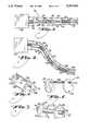
- FIG. 1is a perspective view illustrating a flexible positioning appendage in accordance with the invention, the appendage shown cantilevered from its base (i.e., extending horizontally);
- FIG. 2is perspective view corresponding to FIG. 1, wherein the appendage is curved into a continuous arc;
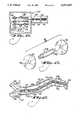
- FIG. 3is an elevation view showing a section along an embodiment of the invention having abutting-turn segment coupling springs
- FIG. 4is an elevation view corresponding to FIG. 3, with the section curved;
- FIGS. 5 through 7are perspective illustrations showing some alternative segment structures
- FIG. 8is an elevation view illustrating application of the invention to a device for positioning a medical instrument
- FIG. 9is a perspective view illustrating application of the invention to a toy monster mask having movable mandible structures
- FIG. 10is an elevation view, partly in section, showing a means for driving the appendages provided in the mask of FIG. 9;
- FIG. 11is a section view through an electrically driven embodiment including a controller
- FIG. 12is an exploded perspective view illustrating a preferred segment structure for a pentagonal arrangement of ranked control lines
- FIG. 13is an elevation view illustrating ranked control lines operable independently to bend different subsections along the longitudinal axis
- FIG. 14is a perspective view of an embodiment having a skin structure disposed over segments, arranged for controlling the aim of a garden hose;
- FIG. 15is a partial elevation view showing joints formed with open springs, rendering the appendage longitudinally compressible
- FIG. 16is a partial elevation view wherein the bending radius is limited by control wire sheaths in a Bowden cable like arrangement
- FIG. 17is a partial elevation view wherein the bending radius is limited by protrusions of the segments
- FIG. 18is a partial cutaway view showing application of the segments to simulate a human hand, including a metacarpal area wherein a plurality of the distally-separate appendages (phalanges) are joined so as to be bendable as a unit;
- FIG. 19is a partially cut away elevation view showing an alternative form of medical instrument having a preferential distal bending area.
- FIG. 20is a perspective view of a boxing toy.
- the inventionis a flexible positioning appendage or arm 30, comprising a plurality of resiliently coupled rigid segments 40 which can be pulled into a curve using control lines 50.
- Each of the segments 40preferably defines an open lumen 62 along a longitudinal axis 64 of the appendage 30, and has at least one flange 66 protruding laterally of the axis.
- each segmentis a rigid element comprising two spaced flanges 66.
- Tubular resilient couplings 72are disposed between each of the rigid segments 40, along the longitudinal axis and preferably aligned with the lumen of the segments.
- the flanges 66each have at least one passage 74 for receiving a control line 50.
- One end 76 of the control lineis fixed to the flange of a segment closer to the distal end 82 of the appendage.
- the control linepasses freely through the flange(s) of each of the segments between this more remote segment and the proximal end 80.
- Meansare provided for applying tension to the control line 50. Provided the tension applied to the control line(s) is laterally unequal relative to the axis 64, the appendage 30 bends laterally toward the control line having the greater tension due to foreshortening of the lateral side of the appendage along which this control line passes. Whereas the coupling between the segments is resilient, the arm bends smoothly, accurately and continuously.
- the appendagecan be arranged to bend only in one direction (requiring only one control line), returning resiliently when tension is released.
- the segments 40have a plurality of passages distributed around the axis 64, and the device comprises a plurality of control lines 50, whereby the appendage is bendable in opposed directions by tension on selected ones of the control lines.
- the appendagecan be arranged to have sections which vary in their susceptibility to bending. It may be desirable, for example, to have a relatively stiffer proximal section for general positioning and a relatively flexible distal section for fine positioning. Sections can be included which are not controllably bendable, and are either flexible or rigid. As one example, when attempting to fish an appendage of this type through branching conduits or the like, it may only be necessary to controllably bend the extreme distal end for guiding the appendage into a desired branch, after which it can be pushed. This can be accomplished by varying the dimensions and the flexibility of the joints between segments as well as the segments themselves.
- a preferred means for varying flexibilityis to vary the length of the spring or other resilient coupling between the segments. For example, shorter (stiffer) connections can be provided near the proximal end or base, and longer (more flexible) connections can be provided approaching the distal end, where greater flexibility and susceptibility to bending is desired.
- the segmentscan be positioned at appropriately varying spacing along the spring, e.g., by screwing the segments along the helical pitch of the spring, and fixed in place.
- the control linescan be arranged in ranks for controlling groups of the segments or even individual segments, at different distances from the proximal end 80. In that case at least one rank 92a (See FIG. 13) of control lines is fixed to a relatively more proximal segment than at least one other rank 92a (see FIG. 13) of control lines.
- the more proximal sections and/or the couplings between the more proximal sectionscan be made stiffer by being larger and heavier, and/or coupled by stiffer resilient couplings than the more distal sections.
- Another means for varying the bending proclivity of the joints along the appendageis to vary the lateral spacing between the axis and the point at which the control lines pass, a relatively more powerful bending force being produced by a relatively greater lateral spacing of the control lines.
- the central axis 64 of the segments 40have an access opening, and the resilient couplings 72 between the segments are hollow.
- the couplingscomprise helical springs 94
- the segments 40each comprise a rigid tube 96 disposed along the axis and at least one flange plate aligned perpendicular to the tube.
- the springs 94are coupled to the rigid tubes 96 of adjacent ones of the segments, either wrapping around the outer surface of the portion of tube 96 which protrudes beyond the flange plate, or being compressed into the lumen of the tube.
- Each segment 40can have two flange plates, the rigid tube protruding from the flange plates at opposite ends of the segment with the spring wrapped thereon.
- the segments 40are of different lengths along the appendage or arm, at least some of the segments at a more proximal position along the arm having a greater spacing between the flange plates than segments at a more distal position.
- a variation in the stiffness of the resilient couplingscan be achieved by using thicker spring wire, shorter axial spring lengths, etc., for the proximal couplings as compared to the distal ones.
- selected jointscan have plural springs disposed inside one another, or a spring joint can be made stiffer by interposing another resilient material such as a length of rubber or plastic, or even a metal spring bar.
- a spring jointcan be made stiffer by interposing another resilient material such as a length of rubber or plastic, or even a metal spring bar.
- the bending proclivity along the appendagecan be chosen as appropriate to the specific task of the appendage.
- Helical springsare preferred where it is desirable to leave open the lumen.
- the helical springs 94 forming a resilient coupling between the segmentspreferably are so-called "closed" springs.
- the springsare wound such that adjacent turns of the springs rest against one another at rest. Accordingly, the adjacent turns 102 on a side of the appendage facing toward a bending radius remain in direct contact, defining a constant length regardless of changes in control line tension, while the turns 104 on the side of the appendage facing away from the bending radius separate, to allow bending.
- FIGS. 3 and 4The same reference numerals have been used throughout the drawings to identify comparable parts in the respective embodiments of the inventions. When at rest (FIG.
- FIGS. 5-7illustrate some alternative forms of segments.
- the illustrated segmentsin each case comprise two spaced flange plates 66, carried on a rigid spacing structure such as a tube, brace or series of braces, whereby each segment is a rigid element.
- the segmentscan be made, for example of polycarbonate or a similar relatively rigid material.
- the segmentscan also be defined by other shapes, provided a passage for a control line spaced laterally of the axis is provided.
- One possible segmentis a simple tube or cylinder having grooves or holes spaced laterally from the center and running parallel to the axis for carrying the control lines. It is also possible to make the segments themselves resilient, e.g., by use of a flexible material to space the flanges.
- a more flexible segment or jointresults in an overall more sinuous and flexible arm, at the expense of accuracy of positioning control.
- a smaller segment, especially a short segment only a single flange,provides relatively greater flexibility than a larger one with spaced flanges, due to the fact that more springs are required over a given length for smaller segments than larger ones, and retains good accuracy of control.
- the triangular flange plate segment 106 in FIG. 5is provided with three passages 74 for control lines 50, and a central opening 62.
- a rigid segment structureis provided by braces 108 at the apices of the flange plates, associated with each of the control line passages 74.
- This arrangementis useful in particular for the segment which forms the distal terminus of the control lines, since the longitudinal tension on the control line tending to pull the segment into a curved orientation is resisted in each case by an associated brace 108.
- the terminus of the control linesis on the distal-side flange 66 of the respective segment, but the terminus could also be on the proximal side or at an intermediate point.
- FIG. 6illustrates a segment 112 arranged to bend in only one direction.
- the brace 108 between the flange platescan be a solid member or a hollow one, e.g., a tube.
- the helical spring for coupling the segments(not shown in FIG. 6) can be wrapped over the protruding end 114 of the brace 108.
- the passage 74 for the control lineis laterally spaced from the coupling defined by the spring and the brace
- an arm 30 using this form of segmentbends toward the control line when tension is applied, or straightens to a point defined by the connecting springs 94 when tension is released.
- This form of segmentis advantageous in connection with an application such as the movable-mandible mask shown in FIGS. 9 and 10.
- the springsprovide the means for recovering when tension is released. By using shorter and thicker springs, the recovery can be positive.
- the springscan be arranged to return the appendage to a straight line or a curved line, either in the same direction as the bend or in the opposite direction, past the centerline.
- FIG. 7illustrates a particular arrangement of the holes 74 provided for passage of the control lines.
- This form of segmentis particularly useful where the appendage is cantilevered, or oriented substantially horizontally, requiring tension on the upper control lines simply to hold the appendage against drooping under the influence of gravity.
- the flangeis a regular pentagon as shown
- the uppermost control lineis centered over the axis 64.
- the side lateral control lines and the lower control linesare placed slightly higher than the respective line between the axis 64 and the corresponding apex of the pentagon.
- the pattern of control linesis shifted vertically relative to the axis 64, giving the operator additional mechanical advantage in overcoming the tendency of the appendage to droop.
- a vertically shifted patterncan also be provided on other flange shapes than pentagons, e.g., round, square, triangular, etc.
- control linesare shifted vertically, but the passages are not equally distributed. More of the control lines are disposed above the longitudinal axis 64 (specifically three control lines) than below it (two). This also makes it easier to control the horizontally oriented arm. In a suitably resilient arm it may be possible to eliminate all the control lines below the axis 64, allowing gravity to bend the arm downwardly when needed.
- the appendageneed not be cantilevered and a symmetrical arrangement of the control wires is appropriate.
- the inventionmay be particularly useful, for example, as a manipulating tool in a zero gravity space environment or underwater, where gravity is less of a problem.
- At least three control linesare needed to enable curving of the appendage in any selected direction.
- curvature in one direction or in limited directionsmay be adequate in many instances.
- the arm 30in this case provides a steerable conduit, for example to admit an endoscope or laparoscope, which enables the operator to curve the distal end 82 to reorient a viewing apparatus or to steer the arm for advance through a body passage.
- curvature in one directionis adequate in this case.
- a pivoting handheld tool 122is coupled to the proximal end 80 of the arm 30 by one of two tip portions 124, and the control line 50 is coupled to the other.
- the tip portions 124are forced apart, thus exerting tension on the control line 50.
- the control linepasses freely through the segments of the arm to an attachment at a segment near the distal end.
- the armcan be arranged to curve from a straight orientation as shown in solid lines, to a curved orientation 130, shown in dashed lines.
- the rest positioncan be curved opposite the direction of curvature, as shown in dash-dot lines 140, enabling the arm to be oriented as required in two opposite directions, while only requiring one control line 50.
- the embodiment according to FIG. 8can be arranged with a plurality of relatively more rigid segments 40 separated by relatively more flexible tube sections 72.
- the control linecan run along a groove in the outer edge of the segments, or through passages spaced from the edge.
- a flexible sheath 142is preferably provided on the outside of the arrangement, with means provided to allow the control line to move under the flexible sheath.
- a plurality of appendages 30are provided on a mask 150, for simulating movable mouth parts 152 on an alien or humanoid monster.
- the maskis made of an elastomeric skin material disposed on a frame as shown in FIG. 10, including a number of movable appendages 30 according to the invention, which can be controllably curved, e.g., inwardly toward the mouth, by application of tension to respective control lines, or released to a rest position upon release of tension.
- the control linescan be run through the material of the mask, for example in embedded guide tubes, to a convenient location for the application of tension.
- Guide tubessuch as Bowden wire tubes can be attached adhesively to the mask, for routing the control lines to a suitable control location.
- a structurecan be provided, for example, to exert tension on the lines when the wearer flexes his or her jaw behind the mask.
- an electromagnetic actuatoris possible, or the control lines may be coupled by a Bowden wire arrangement to a handheld caliper-like manual controller.
- the underlying structure 151forms a relatively rigid base.
- the respective appendages 30have proximal segments 162 which are attached to rigid mask structure 151, with the control lines routed through structure 151 to the interior.
- Each of the appendagescan have one control line, using segments substantially as shown in FIG. 6, coupled by open helical springs. The segments are arranged such that when tension is applied, the appendages foreshorten and curve inwardly as if pulling toward the mouth area. Upon releasing tension, the appendages return to a rest position defined by the springs, which can be straight or curved.
- a plurality of control linescan also be used, for more extensive positioning control.
- FIG. 11illustrates one alternative for an automated and/or electromechanically driven arrangement.
- three control linespass from a proximal segment 162 mounted rigidly on a drive box 164, to motors and controls mounted inside.
- Each control linehas a motor 166 for rotating a threaded shaft 168 carrying a nut 170 to which the respective control lines 50 are attached.
- the three control linesare independently positionable in this manner, and assuming the three lines are distributed around the axis of the arm, the arm can be curved in any direction.
- a microprocessor controller 172is coupled to drive the motors via suitable drivers.
- the motorspreferably are stepping motors and/or are geared for accurate displacement of the control lines over small spans for setting the distal end 82 to predetermined positions, which can be stored in the microprocessor memory.
- Limit switches(not shown) can be provided to reference each movable nut to a zero point.
- a reference position of the arm 30can be defined by manually controlling the arm to place the distal end at a predetermined point, and subsequent movements made relative to the reference position.
- drive unitis also possible.
- motors rotating spools or crank arms to which the control lines are attachedis another possibility.
- the drivecan also employ pneumatic or hydraulic cylinders for applying tension to the control lines, etc.
- the inventionis also applicable for manual drive, and makes an interesting toy.
- the proximal segmentis mounted to a base 182 which can be securely positioned against tension exerted by the operator on the control lines 50.
- the basecan be adapted to be sat upon or knelt upon by the user.
- the control linesare preferably attached at spaced points on one or two control handles 184 as shown in FIG. 13. By pulling on the control handle while canting the control handle relative to the base 182, unequal tension is exerted on the control lines, and the arm is curved in any direction selected as a function of the specific cant of the handle relative to the base.
- FIG. 12shows another form of segment 192, which comprises easily assembled and disassembled parts, which makes this version useful in connection with a toy.
- the flange plateshave central holes including a locking structure such as a dovetail mortise 194, mating with complementary structures 196 on the tube 198 which spaces the flange plates. A snap fit is preferred, whereby the device can be assembled by the user.
- the flange plates according to this embodimenthave passages for ranked control lines, offset vertically from positions at which the control lines would be equiangular around the center axis. Segments of this type can be attached using flexible connectors such as springs.
- FIG. 13illustrates an embodiment wherein the control lines are ranked.
- the more proximal segments 202are relatively larger in diameter and are coupled by relatively stiffer and/or shorter springs. These segments are controlled using one set 204 of three or more control lines, which terminate at a distal one 206 of the larger segments.
- the remaining segments 208 proceeding to the distal end 82 of the arm,are smaller and coupled by relatively more flexible springs.
- the distal segments 208are independently controlled using a group 210 of three or more control lines. This arrangement provides strength and control in the proximal section, for carrying and grossly positioning the arm, as well as dexterity in the distal section.
- the ranked segment arrangementis used together with a variation in the stiffness of the resilient couplings, the more proximal rank of segments being more stiffly coupled than the distal rank of segments.
- This variationcan be achieved by using heavier and/or axially shorter springs in the proximal rank than in the distal rank.
- the control lines 210 for the distal segments 208are disposed radially inwardly toward the axis, and those 204 for the proximal sections 202 are disposed radially outwardly from the axis, the control lines running parallel. Attaching the proximal control lines on the outside provides additional leverage in positioning the arm by application of tension.
- each set of control linescan be attached to a handle 184 which can be pulled and/or tilted relative to the base and the fixed proximal segment 162, for exerting unequal tension.
- the arm of FIG. 12can be formed into a compound bend, with the proximal rank bent in one direction and the distal rank in another direction.
- the controlsare generally limited to two ranks, operable with a control handle for each or the user's hands.
- An automated controladvantageously can have a larger number of ranks.
- the control lines for the more proximal ranksare arranged along the outer portions of the proximal flange plates, with the more distal ranks placed radially inward, running through the proximal segments to their respective connections of segments located closer to the distal end of the arm.
- the inventionis subject to wide variations.
- the proximal segmentsare generally larger, not all the segments need be of the same length and it is possible that using longer distal segments may be appropriate for some applications, such as spray painting, wherein a sweeping distal motion may be needed to move a spray head over a path.
- the inventioncan be applied to intermediate joints or elbows, as well as to the distal end of an automated appendage. The invention is also apt for a wide variety of specific applications, only a few examples being discussed herein.
- FIG. 14illustrates application of the invention to a toy 220 used for aiming a garden hose 224.
- a joystick-like manual control 222is coupled to the base 182 of the device for operating the control lines.
- the segmentsshown in phantom lines, are progressively smaller leading to the free end, and are connected by springs leaving a lumen of sufficient size to receive the garden hose 224.
- the appendage portion of the toyis covered by a sock or similar skin 225, stretched over the segments.
- the segmentscan be potted in a soft foam plastic or the like.
- the springscan be open springs as shown in FIG. 15, or closed springs as shown in FIG. 16.
- FIG. 16illustrates an embodiment wherein the control lines are carried in sheaths 232 extending through the segments 40, or at least protruding from the ends of the segments.
- the sheaths 232preferably are flexible and attached to the segment flanges by adhesive, being of a material similar to bicycle brake cable sheathing.
- the sheaths 232have the further aspect of limiting the minimum bending radius which can be achieve by tension on the control lines.
- FIG. 17achieves a similar limitation on the minimum bending radius by means of spacers 242 provided on the ends of the segments, which contact the adjacent segment to define the minimum radius.
- the segmentscan have such spacers on one side only, or on both sides as shown.
- FIG. 18is an example of an arrangement wherein the control lines are ranked, but the different ranks are materially different forms of appendage.
- FIG. 18is a partial cutaway view showing application of the invention to simulate a human hand.
- the fingersare simulated by separate appendages 30 substantially as discussed above.
- the segmentscan be dimensioned similarly to the finger bones of the human hand, thus simulating the knuckles in the fingers or phalanges.
- the separate phalange appendagesare joined at a one or more proximal ranks so as to be bendable in at least one plane as a unit, thus simulating natural grasping motions.
- metacarpal segments 254Four fingers can be mounted on metacarpal segments 254, or pairs of two fingers can be mounted on metacarpal segments in a similar manner.
- the series of segments 30separately from the phalanges to the carpus, as characteristic of the bones of human hands.
- the metacarpal segments 254, whether separate or joined as shown,are operably via a separate rank of control lines, thus enabling the fingers to be flexed or extended without also bending across the palm, and vice versa.
- FIG. 19is a partially cut away elevation view showing an alternative form of medical instrument 262 having a preferential distal bending area 266.
- This instrumentis provided with a less flexible or less controllable proximal section 264 and a very flexible extreme distal end 266, for guiding the instrument.
- the instrumentis useful for procedures such as bronchial suctioning, wherein it is necessary to guide a suction apparatus through branching bronchial passages. The user can readily select between passages at a branch by diverting the distal end 266 of the instrument using unequal control line tension.
- the instrument of FIG. 19is preferably constructed of a substantially continuous flexible plastic, having segments 270 embedded in a plastic body 268 during molding.
- the segmentsshown in dotted lines in FIG. 19, are more closely spaced at the less flexible proximal end 264, and less closely spaced at the distal end 266, where preferential bending is desired.
- FIG. 20illustrates another embodiment of a toy 282.
- the appendagecomprises a continuous body 284 of soft plastic such as foamed polyurethane.
- the control linesextend through openings running along the length of the appendage, which may be strengthened by compressible guide tubes 286 or by spaced lengths of non-compressible guide tubing. Paths for the control lines can be formed by displacing the control lines in the potting material before it has fully set, to disengage the control lines from the potting and/or to enlarge the openings for the control lines.
- a rigid segment plate 288is provided near the distal end for attachment of the control lines.
- a soft bulb 292covers the rigid distal segment plate 288, to avoid injury.
- This toyis a form of soft boxing toy, intended to allow two participants to assume closely facing positions and to control their respective soft appendages to strike at one another.
Landscapes
- Engineering & Computer Science (AREA)
- Health & Medical Sciences (AREA)
- Life Sciences & Earth Sciences (AREA)
- Robotics (AREA)
- Surgery (AREA)
- Medical Informatics (AREA)
- Biomedical Technology (AREA)
- Heart & Thoracic Surgery (AREA)
- Nuclear Medicine, Radiotherapy & Molecular Imaging (AREA)
- Molecular Biology (AREA)
- Animal Behavior & Ethology (AREA)
- General Health & Medical Sciences (AREA)
- Public Health (AREA)
- Veterinary Medicine (AREA)
- Mechanical Engineering (AREA)
- Toys (AREA)
Abstract
Description
Claims (17)
Priority Applications (3)
| Application Number | Priority Date | Filing Date | Title |
|---|---|---|---|
| US07/909,960US5297443A (en) | 1992-07-07 | 1992-07-07 | Flexible positioning appendage |
| AU60163/94AAU6016394A (en) | 1992-07-07 | 1993-12-29 | Flexible positioning appendage |
| PCT/US1993/012647WO1995018311A1 (en) | 1992-07-07 | 1993-12-29 | Flexible positioning appendage |
Applications Claiming Priority (2)
| Application Number | Priority Date | Filing Date | Title |
|---|---|---|---|
| US07/909,960US5297443A (en) | 1992-07-07 | 1992-07-07 | Flexible positioning appendage |
| PCT/US1993/012647WO1995018311A1 (en) | 1992-07-07 | 1993-12-29 | Flexible positioning appendage |
Publications (1)
| Publication Number | Publication Date |
|---|---|
| US5297443Atrue US5297443A (en) | 1994-03-29 |
Family
ID=25428108
Family Applications (1)
| Application Number | Title | Priority Date | Filing Date |
|---|---|---|---|
| US07/909,960Expired - LifetimeUS5297443A (en) | 1992-07-07 | 1992-07-07 | Flexible positioning appendage |
Country Status (3)
| Country | Link |
|---|---|
| US (1) | US5297443A (en) |
| AU (1) | AU6016394A (en) |
| WO (1) | WO1995018311A1 (en) |
Cited By (195)
| Publication number | Priority date | Publication date | Assignee | Title |
|---|---|---|---|---|
| US5816769A (en)* | 1995-11-07 | 1998-10-06 | Siemens Aktiengesellschaft | Flexible manipulator |
| US5842381A (en)* | 1994-07-28 | 1998-12-01 | Siemens Aktiengesellschaft | Precisely controllable flexible actuator |
| US6458010B1 (en)* | 1999-02-19 | 2002-10-01 | Sony Corporation | Curving mechanism and robot |
| US6532601B1 (en)* | 2001-10-10 | 2003-03-18 | Robert Berman | Headgear with manipulatable projections |
| US6726181B1 (en) | 2002-11-30 | 2004-04-27 | Bellsouth Intellectual Property Corporation | Apparatus and method for routing cables and wires |
| US20040121707A1 (en)* | 2001-05-17 | 2004-06-24 | Cameron Drake | Gentle-acting carrier-based glass-like polysaccharide abrasive grit |
| US6773327B1 (en)* | 2002-02-12 | 2004-08-10 | Hasbro, Inc. | Apparatus for actuating a toy |
| US6800016B2 (en) | 2002-05-31 | 2004-10-05 | Mattel, Inc. | Flexible dolls and posable action figures |
| US20040206529A1 (en)* | 2003-04-17 | 2004-10-21 | Charlie Sawyer | Glow rods with externally mountable anchoring members and related methods |
| US6843703B1 (en) | 2003-04-30 | 2005-01-18 | Hasbro, Inc. | Electromechanical toy |
| US20050020901A1 (en)* | 2000-04-03 | 2005-01-27 | Neoguide Systems, Inc., A Delaware Corporation | Apparatus and methods for facilitating treatment of tissue via improved delivery of energy based and non-energy based modalities |
| US6858005B2 (en) | 2000-04-03 | 2005-02-22 | Neo Guide Systems, Inc. | Tendon-driven endoscope and methods of insertion |
| US20050107667A1 (en)* | 2003-05-23 | 2005-05-19 | Novare Surgical Systems, Inc. | Hand-actuated device for remote manipulation of a grasping tool |
| US20050145727A1 (en)* | 2003-12-26 | 2005-07-07 | Steingass Robert W. | Segmented monitor |
| US20050154258A1 (en)* | 2000-04-03 | 2005-07-14 | Tartaglia Joseph M. | Endoscope with adjacently positioned guiding apparatus |
| US20050191936A1 (en)* | 2004-01-07 | 2005-09-01 | Marine Jon C. | Doll |
| US20050222498A1 (en)* | 2000-04-03 | 2005-10-06 | Amir Belson | Steerable endoscope and improved method of insertion |
| US20050251112A1 (en)* | 2003-05-23 | 2005-11-10 | Danitz David J | Articulating mechanism for remote manipulation of a surgical or diagnostic tool |
| US20050273084A1 (en)* | 2004-06-07 | 2005-12-08 | Novare Surgical Systems, Inc. | Link systems and articulation mechanisms for remote manipulation of surgical or diagnostic tools |
| US20050273085A1 (en)* | 2004-06-07 | 2005-12-08 | Novare Surgical Systems, Inc. | Articulating mechanism with flex-hinged links |
| US20060007360A1 (en)* | 2004-07-09 | 2006-01-12 | Kim Hee C | Display apparatus and method for reproducing color therewith |
| US20060052664A1 (en)* | 2000-04-03 | 2006-03-09 | Julian Christopher A | Connector device for a controllable instrument |
| US20060089535A1 (en)* | 2002-07-11 | 2006-04-27 | Dan Raz | Piston-actuated endoscopic steering system |
| US20060111615A1 (en)* | 2004-11-23 | 2006-05-25 | Novare Surgical Systems, Inc. | Articulating sheath for flexible instruments |
| US20060111616A1 (en)* | 2004-11-24 | 2006-05-25 | Novare Surgical Systems, Inc. | Articulating mechanism components and system for easy assembly and disassembly |
| US20060111210A1 (en)* | 2004-11-23 | 2006-05-25 | Novare Surgical Systems, Inc. | Articulating mechanisms and link systems with torque transmission in remote manipulation of instruments and tools |
| US20060156851A1 (en)* | 2004-12-02 | 2006-07-20 | Jacobsen Stephen C | Mechanical serpentine device |
| US20060201130A1 (en)* | 2005-01-31 | 2006-09-14 | Danitz David J | Articulating mechanisms with joint assembly and manual handle for remote manipulation of instruments and tools |
| US20060235457A1 (en)* | 2005-04-15 | 2006-10-19 | Amir Belson | Instruments having a rigidizable external working channel |
| US20060258912A1 (en)* | 2000-04-03 | 2006-11-16 | Amir Belson | Activated polymer articulated instruments and methods of insertion |
| US20070021032A1 (en)* | 2003-01-14 | 2007-01-25 | Disney Enterprises, Inc. | Skeletal support structure and skin for an animatronic figure |
| US20070135803A1 (en)* | 2005-09-14 | 2007-06-14 | Amir Belson | Methods and apparatus for performing transluminal and other procedures |
| US20070161291A1 (en)* | 2005-11-23 | 2007-07-12 | Neoguide Systems, Inc. | Non-metallic, multi-strand control cable for steerable instruments |
| US20070241714A1 (en)* | 2003-07-08 | 2007-10-18 | Board Or Regents Of The University Of Nebraska | Robot for surgical applications |
| US20070250113A1 (en)* | 2003-05-23 | 2007-10-25 | Hegeman David E | Tool with articulation lock |
| US20070249901A1 (en)* | 2003-03-07 | 2007-10-25 | Ohline Robert M | Instrument having radio frequency identification systems and methods for use |
| US20070270650A1 (en)* | 2006-05-19 | 2007-11-22 | Robert Eno | Methods and apparatus for displaying three-dimensional orientation of a steerable distal tip of an endoscope |
| US20070287993A1 (en)* | 2006-06-13 | 2007-12-13 | Hinman Cameron D | Tool with rotation lock |
| US20080004634A1 (en)* | 2006-06-22 | 2008-01-03 | Board Of Regents Of The University Of Nebraska | Magnetically coupleable robotic surgical devices and related methods |
| US20080111513A1 (en)* | 2003-07-08 | 2008-05-15 | Board Of Regents Of The University Of Nebraska | Robot for surgical applications |
| US20080132761A1 (en)* | 2004-09-23 | 2008-06-05 | Minelu Sonnenschein | Articulation Section |
| US20080136254A1 (en)* | 2006-11-13 | 2008-06-12 | Jacobsen Stephen C | Versatile endless track for lightweight mobile robots |
| US20080164080A1 (en)* | 2004-12-09 | 2008-07-10 | Asbeck Alan T | Biologically inspired climbing device |
| US20080164079A1 (en)* | 2006-11-13 | 2008-07-10 | Jacobsen Stephen C | Serpentine robotic crawler |
| US20080167752A1 (en)* | 2006-11-13 | 2008-07-10 | Jacobsen Stephen C | Tracked robotic crawler having a moveable arm |
| US20080215185A1 (en)* | 2006-11-13 | 2008-09-04 | Jacobsen Stephen C | Unmanned ground robotic vehicle having an alternatively extendible and retractable sensing appendage |
| US20080221591A1 (en)* | 2007-02-20 | 2008-09-11 | Board Of Regents Of The University Of Nebraska | Methods, systems, and devices for surgical visualization and device manipulation |
| US20080255608A1 (en)* | 2007-04-16 | 2008-10-16 | Hinman Cameron D | Tool with end effector force limiter |
| US20080255421A1 (en)* | 2007-04-16 | 2008-10-16 | David Elias Hegeman | Articulating tool with improved tension member system |
| US20080255588A1 (en)* | 2007-04-16 | 2008-10-16 | Hinman Cameron D | Tool with multi-state ratcheted end effector |
| US20080281468A1 (en)* | 2007-05-08 | 2008-11-13 | Raytheon Sarcos, Llc | Variable primitive mapping for a robotic crawler |
| US20080302200A1 (en)* | 2007-06-06 | 2008-12-11 | Tobey Wayland E | Modular hybrid snake arm |
| US20090005645A1 (en)* | 2005-05-04 | 2009-01-01 | Frassica James J | Rotate-to- advance catheterization system |
| US20090012648A1 (en)* | 2006-01-06 | 2009-01-08 | Robert Oliver Buckingham | Robotic Arms With Coaxially Mounted Helical Spring Means |
| US20090025988A1 (en)* | 2007-07-10 | 2009-01-29 | Jacobsen Stephen C | Serpentine Robotic Crawler Having A Continuous Track |
| US20090030562A1 (en)* | 2007-07-10 | 2009-01-29 | Jacobsen Stephen C | Modular Robotic Crawler |
| US20090048612A1 (en)* | 2007-08-15 | 2009-02-19 | Board Of Regents Of The University Of Nebraska | Modular and cooperative medical devices and related systems and methods |
| US20090054909A1 (en)* | 2007-07-12 | 2009-02-26 | Board Of Regents Of The University Of Nebraska | Methods and systems of actuation in robotic devices |
| US20090076536A1 (en)* | 2007-08-15 | 2009-03-19 | Board Of Regents Of The University Of Nebraska | Medical inflation, attachment, and delivery devices and related methods |
| US20090171373A1 (en)* | 2007-06-21 | 2009-07-02 | Farritor Shane M | Multifunctional operational component for robotic devices |
| US20090216083A1 (en)* | 2008-02-25 | 2009-08-27 | Neoguide Systems, Inc. | Systems and Methods for Articulating an Elongate Body |
| US20100041945A1 (en)* | 2008-08-18 | 2010-02-18 | Isbell Jr Lewis | Instrument with articulation lock |
| US7695341B1 (en) | 2002-11-27 | 2010-04-13 | Hasbro, Inc. | Electromechanical toy |
| US20100174422A1 (en)* | 2009-01-08 | 2010-07-08 | Jacobsen Stephen C | Point And Go Navigation System And Method |
| US20100201185A1 (en)* | 2006-11-13 | 2010-08-12 | Raytheon Sarcos, Llc | Conformable Track Assembly For A Robotic Crawler |
| US20100317244A1 (en)* | 2009-06-11 | 2010-12-16 | Jacobsen Stephen C | Amphibious Robotic Crawler |
| US20100318242A1 (en)* | 2009-06-11 | 2010-12-16 | Jacobsen Stephen C | Method And System For Deploying A Surveillance Network |
| US20110065993A1 (en)* | 2000-04-03 | 2011-03-17 | Amir Belson | Steerable segmented endoscope and method of insertion |
| US20110132129A1 (en)* | 2009-12-04 | 2011-06-09 | Hong Fu Jin Precision Industry (Shenzhen) Co., Ltd. | Robot arm assembly |
| US7960935B2 (en) | 2003-07-08 | 2011-06-14 | The Board Of Regents Of The University Of Nebraska | Robotic devices with agent delivery components and related methods |
| US20110162477A1 (en)* | 2010-01-07 | 2011-07-07 | Samsung Electronics Co., Ltd. | Robot |
| US20110178370A1 (en)* | 1997-02-10 | 2011-07-21 | Frassica James J | Rotate to advance catheterization system |
| US8002716B2 (en) | 2007-05-07 | 2011-08-23 | Raytheon Company | Method for manufacturing a complex structure |
| US20110237890A1 (en)* | 2009-12-17 | 2011-09-29 | Board Of Regents Of The University Of Nebraska | Modular and cooperative medical devices and related systems and methods |
| US20110277579A1 (en)* | 2010-05-14 | 2011-11-17 | Intuitive Surgical Operations, Inc. | Cable Re-ordering Device |
| CN102744732A (en)* | 2012-06-20 | 2012-10-24 | 东莞东聚电子电讯制品有限公司 | A snake-like robotic arm |
| US20120279401A1 (en)* | 2011-05-06 | 2012-11-08 | Prince Castle LLC | Egg Scrambler for Preparing Scrambled Eggs |
| US8347754B1 (en)* | 2008-07-02 | 2013-01-08 | Titan Medical Inc. | Multi articulating robatic instrument |
| DE102012106595A1 (en) | 2011-07-20 | 2013-01-24 | Mattel, Inc. | Flexible toy figure with armature |
| US8361090B2 (en) | 2002-01-09 | 2013-01-29 | Intuitive Surgical Operations, Inc. | Apparatus and method for endoscopic colectomy |
| US20130047755A1 (en)* | 2011-02-28 | 2013-02-28 | Olympus Medical Systems Corp. | Bending operation apparatus |
| US8393422B1 (en) | 2012-05-25 | 2013-03-12 | Raytheon Company | Serpentine robotic crawler |
| US8419767B2 (en)* | 2010-05-04 | 2013-04-16 | Mustafa H. Al-Qbandi | Steerable atrial septal occluder implantation device with flexible neck |
| CN103085083A (en)* | 2013-01-07 | 2013-05-08 | 汪雯 | Flexible continuous body mechanical structure capable of bending and stretching |
| WO2013144258A1 (en)* | 2012-03-30 | 2013-10-03 | Beglan Philip Michael Peter | Transformable cable volume structure |
| US20140058364A1 (en)* | 2011-02-14 | 2014-02-27 | Intuitive Surgical Operations, Inc. | Jointed link structures exhibiting preferential bending, and related methods |
| US20140066951A1 (en)* | 2009-10-28 | 2014-03-06 | New York University | Cochlear implant with improved electrode array and controller |
| US8747300B2 (en) | 2005-05-04 | 2014-06-10 | Olympus Endo Technology America Inc. | Rotate-to-advance catheterization system |
| US8777841B2 (en) | 2007-05-18 | 2014-07-15 | Olympus Endo Technology America Inc. | Rotate-to-advance catheterization system |
| US20140309684A1 (en)* | 2013-04-10 | 2014-10-16 | Mustafa H. Al-Qbandi | Atrial septal occluder device and method |
| US8968267B2 (en) | 2010-08-06 | 2015-03-03 | Board Of Regents Of The University Of Nebraska | Methods and systems for handling or delivering materials for natural orifice surgery |
| US20150088161A1 (en)* | 2013-09-20 | 2015-03-26 | Canon U.S.A., Inc. | Control apparatus and tendon-driven device |
| US8992421B2 (en) | 2010-10-22 | 2015-03-31 | Medrobotics Corporation | Highly articulated robotic probes and methods of production and use of such probes |
| US9010214B2 (en) | 2012-06-22 | 2015-04-21 | Board Of Regents Of The University Of Nebraska | Local control robotic surgical devices and related methods |
| US9031698B2 (en) | 2012-10-31 | 2015-05-12 | Sarcos Lc | Serpentine robotic crawler |
| US9060781B2 (en) | 2011-06-10 | 2015-06-23 | Board Of Regents Of The University Of Nebraska | Methods, systems, and devices relating to surgical end effectors |
| US9089353B2 (en) | 2011-07-11 | 2015-07-28 | Board Of Regents Of The University Of Nebraska | Robotic surgical devices, systems, and related methods |
| US20150209215A1 (en)* | 2014-01-24 | 2015-07-30 | Samsung Electronics Co., Ltd. | Holder and walking assistant robot having the same |
| US9161771B2 (en) | 2011-05-13 | 2015-10-20 | Intuitive Surgical Operations Inc. | Medical instrument with snake wrist structure |
| DE102011108262B4 (en)* | 2011-07-25 | 2015-12-17 | Eisenmann Ag | Apparatus for painting vehicle bodies with a plurality of gestaltveranderlichen arms |
| US9221179B2 (en) | 2009-07-23 | 2015-12-29 | Intuitive Surgical Operations, Inc. | Articulating mechanism |
| US9220395B2 (en) | 1999-09-27 | 2015-12-29 | James J. Frassica | Rotate-to-advance catheterization system |
| US9220398B2 (en) | 2007-10-11 | 2015-12-29 | Intuitive Surgical Operations, Inc. | System for managing Bowden cables in articulating instruments |
| US20160008990A1 (en)* | 2014-07-09 | 2016-01-14 | Scholly Fiberoptic Gmbh | Manipulation and/or examination instrument |
| US9333040B2 (en) | 2012-02-02 | 2016-05-10 | Transenterix Surgical, Inc. | Mechanized multi-instrument surgical system |
| US9364955B2 (en) | 2011-12-21 | 2016-06-14 | Medrobotics Corporation | Stabilizing apparatus for highly articulated probes with link arrangement, methods of formation thereof, and methods of use thereof |
| US9375206B2 (en) | 2011-08-25 | 2016-06-28 | Endocontrol | Surgical instrument with disengageable handle |
| US9409292B2 (en) | 2013-09-13 | 2016-08-09 | Sarcos Lc | Serpentine robotic crawler for performing dexterous operations |
| EP3072642A3 (en)* | 2015-03-23 | 2016-10-19 | Rolls-Royce plc | Flexible tools and apparatus for machining objects |
| US20160302817A1 (en)* | 2015-04-16 | 2016-10-20 | Ethicon Endo-Surgery, Llc | Ultrasonic surgical instrument with articulation joint having plurality of locking positions |
| US9498112B1 (en) | 2013-03-15 | 2016-11-22 | Brent Stewart | Laryngoscope |
| US9498292B2 (en) | 2012-05-01 | 2016-11-22 | Board Of Regents Of The University Of Nebraska | Single site robotic device and related systems and methods |
| US9566711B2 (en) | 2014-03-04 | 2017-02-14 | Sarcos Lc | Coordinated robotic control |
| US9572628B2 (en) | 2011-09-13 | 2017-02-21 | Medrobotics Corporation | Highly articulated probes with anti-twist link arrangement, methods of formation thereof, and methods of performing medical procedures |
| TWI581749B (en)* | 2013-03-22 | 2017-05-11 | Endoscopic joint structure with compound bending curvature | |
| US9649163B2 (en) | 2010-11-11 | 2017-05-16 | Medrobotics Corporation | Introduction devices for highly articulated robotic probes and methods of production and use of such probes |
| US9675380B2 (en) | 2012-08-09 | 2017-06-13 | Medrobotics Corporation | Surgical tool positioning system |
| US9675370B2 (en) | 2008-04-11 | 2017-06-13 | The Regents Of The University Of Michigan | Minimal access tool |
| CN106926223A (en)* | 2015-12-30 | 2017-07-07 | 中国科学院沈阳自动化研究所 | A kind of snake-shaped robot |
| US9743987B2 (en) | 2013-03-14 | 2017-08-29 | Board Of Regents Of The University Of Nebraska | Methods, systems, and devices relating to robotic surgical devices, end effectors, and controllers |
| US9770305B2 (en) | 2012-08-08 | 2017-09-26 | Board Of Regents Of The University Of Nebraska | Robotic surgical devices, systems, and related methods |
| US9814451B2 (en) | 2015-10-02 | 2017-11-14 | Flexdex, Inc. | Handle mechanism providing unlimited roll |
| CN107433579A (en)* | 2017-06-27 | 2017-12-05 | 西北工业大学 | A kind of bionical tail apparatus of more piece of SMA drivings |
| US9869339B2 (en) | 2008-04-11 | 2018-01-16 | Flexdex, Inc. | End-effector jaw closure transmission systems for remote access tools |
| US9888966B2 (en) | 2013-03-14 | 2018-02-13 | Board Of Regents Of The University Of Nebraska | Methods, systems, and devices relating to force control surgical systems |
| US9901410B2 (en) | 2010-07-28 | 2018-02-27 | Medrobotics Corporation | Surgical positioning and support system |
| US9913695B2 (en) | 2013-05-02 | 2018-03-13 | Medrobotics Corporation | Robotic system including a cable interface assembly |
| WO2018093056A1 (en)* | 2016-11-16 | 2018-05-24 | 재단법인 아산사회복지재단 | Device for driving robot joint using wire, endoscope robot device comprising same, and medical robot device comprising same |
| US20180154515A1 (en)* | 2016-12-02 | 2018-06-07 | Rolls-Royce Plc | Hyper redundant robots |
| US10004568B2 (en) | 2013-12-30 | 2018-06-26 | Medrobotics Corporation | Articulating robotic probes |
| JP2018517457A (en)* | 2015-04-27 | 2018-07-05 | フォンダツィオーネ インスティテゥート イタリアーノ ディ テクノロジア | Shape maintaining and deployable structure including a pair of continuous robot systems |
| CN108356797A (en)* | 2018-02-02 | 2018-08-03 | 西安电子科技大学 | A kind of spring-rope drive lacking space mechanism arm device |
| CN108568838A (en)* | 2018-04-08 | 2018-09-25 | 西安交通大学 | A kind of heavy load flexible manipulator based on rigid constraint |
| CN108673558A (en)* | 2018-05-28 | 2018-10-19 | 哈尔滨工业大学 | Variation rigidity flexible motion arm |
| US20190009758A1 (en)* | 2015-09-02 | 2019-01-10 | Evolution Technologies Inc. | Brake assembly for height-adjustable patient transport apparatus |
| CN109278034A (en)* | 2018-10-24 | 2019-01-29 | 哈尔滨工业大学(深圳) | A rope-driven flexible gripper and robot |
| US10342561B2 (en) | 2014-09-12 | 2019-07-09 | Board Of Regents Of The University Of Nebraska | Quick-release end effectors and related systems and methods |
| US10376322B2 (en) | 2014-11-11 | 2019-08-13 | Board Of Regents Of The University Of Nebraska | Robotic device with compact joint design and related systems and methods |
| US10406571B2 (en) | 2016-03-08 | 2019-09-10 | Alexander G. Innes | Mechanical extended reach Sluicer |
| US10405936B2 (en) | 2008-04-11 | 2019-09-10 | The Regents Of The University Of Michigan | Parallel kinematic mechanisms with decoupled rotational motions |
| US10500372B2 (en) | 2017-08-02 | 2019-12-10 | Farshad Malekmehr | Guidewire |
| US10512392B2 (en) | 2008-02-06 | 2019-12-24 | Intuitive Surgical Operations, Inc. | Segmented instrument having braking capabilities |
| USD874655S1 (en) | 2018-01-05 | 2020-02-04 | Medrobotics Corporation | Positioning arm for articulating robotic surgical system |
| US10582973B2 (en) | 2012-08-08 | 2020-03-10 | Virtual Incision Corporation | Robotic surgical devices, systems, and related methods |
| US10653861B2 (en) | 2014-05-02 | 2020-05-19 | Intellimedical Technologies Pty. Ltd. | Elongate steerable devices for insertion into a subjects body |
| US10667883B2 (en) | 2013-03-15 | 2020-06-02 | Virtual Incision Corporation | Robotic surgical devices, systems, and related methods |
| CN111317570A (en)* | 2018-12-13 | 2020-06-23 | 中国科学院沈阳自动化研究所 | Deformation linkage mechanism |
| WO2020135748A1 (en)* | 2018-12-28 | 2020-07-02 | 北京术锐技术有限公司 | Flexible surgical tool system |
| US10702347B2 (en) | 2016-08-30 | 2020-07-07 | The Regents Of The University Of California | Robotic device with compact joint design and an additional degree of freedom and related systems and methods |
| US10722319B2 (en) | 2016-12-14 | 2020-07-28 | Virtual Incision Corporation | Releasable attachment device for coupling to medical devices and related systems and methods |
| US10753439B2 (en) | 2015-04-03 | 2020-08-25 | The Regents Of The University Of Michigan | Tension management apparatus for cable-driven transmission |
| US10751136B2 (en) | 2016-05-18 | 2020-08-25 | Virtual Incision Corporation | Robotic surgical devices, systems and related methods |
| US10786905B1 (en) | 2018-04-16 | 2020-09-29 | AGI Engineering, Inc. | Tank excavator |
| US10806538B2 (en) | 2015-08-03 | 2020-10-20 | Virtual Incision Corporation | Robotic surgical devices, systems, and related methods |
| CN112022238A (en)* | 2020-08-28 | 2020-12-04 | 中国科学院沈阳自动化研究所 | A surgical instrument for a minimally invasive surgical robot |
| US10864640B1 (en) | 2017-12-26 | 2020-12-15 | AGI Engineering, Inc. | Articulating arm programmable tank cleaning nozzle |
| CN112296990A (en)* | 2020-10-27 | 2021-02-02 | 浙江理工大学 | A bionic sea snake robot based on rope traction |
| US10959797B2 (en) | 2015-10-05 | 2021-03-30 | Flexdex, Inc. | Medical devices having smoothly articulating multi-cluster joints |
| US10966700B2 (en) | 2013-07-17 | 2021-04-06 | Virtual Incision Corporation | Robotic surgical devices, systems and related methods |
| US20210106488A1 (en)* | 2019-10-11 | 2021-04-15 | Neurolutions, Inc. | Orthosis Systems and Rehabilitation of Impaired Body Parts |
| US11013564B2 (en) | 2018-01-05 | 2021-05-25 | Board Of Regents Of The University Of Nebraska | Single-arm robotic device with compact joint design and related systems and methods |
| US11031149B1 (en) | 2018-02-13 | 2021-06-08 | AGI Engineering, Inc. | Nuclear abrasive slurry waste pump with backstop and macerator |
| US11051894B2 (en) | 2017-09-27 | 2021-07-06 | Virtual Incision Corporation | Robotic surgical devices with tracking camera technology and related systems and methods |
| US11097430B2 (en)* | 2017-10-31 | 2021-08-24 | Worcester Polytechnic Institute | Robotic gripper member |
| CN113290550A (en)* | 2021-05-26 | 2021-08-24 | 北京理工大学 | Scalable bionical trunk device based on pneumatic artificial muscle drive of Mckiben type |
| US11096563B2 (en) | 2005-11-22 | 2021-08-24 | Intuitive Surgical Operations, Inc. | Method of determining the shape of a bendable instrument |
| US11117268B2 (en) | 2019-06-26 | 2021-09-14 | Timothy R. Beevers | Robot appendage |
| US11173617B2 (en) | 2016-08-25 | 2021-11-16 | Board Of Regents Of The University Of Nebraska | Quick-release end effector tool interface |
| WO2022013469A1 (en)* | 2020-07-14 | 2022-01-20 | Universidad Carlos Iii De Madrid | Link for soft joint and soft joint comprising the link |
| US20220031324A1 (en)* | 2020-07-28 | 2022-02-03 | Cilag Gmbh International | Surgical instruments with dual spherical articulation joint arrangements |
| JP2022514232A (en)* | 2018-12-28 | 2022-02-10 | 北京▲術▼▲鋭▼技▲術▼有限公司 | Double-curved flexible surgical instrument system |
| US11267024B2 (en) | 2018-06-11 | 2022-03-08 | AGI Engineering, Inc. | Programmable tank cleaning nozzle |
| US11284958B2 (en) | 2016-11-29 | 2022-03-29 | Virtual Incision Corporation | User controller with user presence detection and related systems and methods |
| US11311920B2 (en) | 2018-06-11 | 2022-04-26 | AGI Engineering, Inc. | Programmable railcar tank cleaning system |
| WO2022119727A1 (en)* | 2020-12-04 | 2022-06-09 | Universal City Studios Llc | Conical -shaped articulated member |
| US11357595B2 (en) | 2016-11-22 | 2022-06-14 | Board Of Regents Of The University Of Nebraska | Gross positioning device and related systems and methods |
| US11413666B1 (en) | 2018-02-13 | 2022-08-16 | AGI Engineering, Inc. | Vertical travel robotic tank cleaning system |
| US11440182B2 (en)* | 2017-04-25 | 2022-09-13 | Sony Corporation | Expansion device and movable body |
| TWI781798B (en)* | 2021-09-22 | 2022-10-21 | 新加坡商先進科技新加坡有限公司 | Flexural pick arm for a pick and place apparatus |
| WO2022243363A1 (en) | 2021-05-20 | 2022-11-24 | Ambu A/S | Endoscope comprising a bending section having a varying length of hinges |
| US11571723B1 (en) | 2019-03-29 | 2023-02-07 | AGI Engineering, Inc. | Mechanical dry waste excavating end effector |
| US11577287B1 (en) | 2018-04-16 | 2023-02-14 | AGI Engineering, Inc. | Large riser extended reach sluicer and tool changer |
| CN116616679A (en)* | 2023-04-21 | 2023-08-22 | 深圳市星辰海医疗科技有限公司 | Tip bending section of endoscope and endoscope |
| GB2616504A (en)* | 2022-02-09 | 2023-09-13 | Deutsch Zentr Luft & Raumfahrt | System for endoscopic positioning |
| EP4023395A4 (en)* | 2019-08-29 | 2023-10-04 | Korea Advanced Institute of Science and Technology | FLEXIBLE ACTUATOR |
| US11865702B2 (en) | 2017-10-31 | 2024-01-09 | Worcester Polytechnic Institute | Robotic gripper member |
| US11883065B2 (en) | 2012-01-10 | 2024-01-30 | Board Of Regents Of The University Of Nebraska | Methods, systems, and devices for surgical access and insertion |
| US11896255B2 (en) | 2015-10-05 | 2024-02-13 | Flexdex, Inc. | End-effector jaw closure transmission systems for remote access tools |
| US11903658B2 (en) | 2019-01-07 | 2024-02-20 | Virtual Incision Corporation | Robotically assisted surgical system and related devices and methods |
| US11950966B2 (en) | 2020-06-02 | 2024-04-09 | Flexdex, Inc. | Surgical tool and assembly |
| US12150722B2 (en) | 2020-07-06 | 2024-11-26 | Virtual Incision Corporation | Surgical robot positioning system and related devices and methods |
| US12156710B2 (en) | 2011-10-03 | 2024-12-03 | Virtual Incision Corporation | Robotic surgical devices, systems and related methods |
| US12295680B2 (en) | 2012-08-08 | 2025-05-13 | Board Of Regents Of The University Of Nebraska | Robotic surgical devices, systems and related methods |
| US12311550B2 (en) | 2020-12-31 | 2025-05-27 | Sarcos Corp. | Smart control system for a robotic device |
| US12390293B2 (en) | 2016-02-25 | 2025-08-19 | Shorya Awtar | Parallel kinematic mechanisms with decoupled rotational motions |
Families Citing this family (12)
| Publication number | Priority date | Publication date | Assignee | Title |
|---|---|---|---|---|
| AU2001248487A1 (en)* | 2000-04-21 | 2001-11-07 | Universite Pierre Et Marie Curie (Paris Vi) | Device for positioning, exploring and/or operating in particular in the field ofendoscopy and/or minimally invasive surgery |
| US7250027B2 (en)* | 2002-05-30 | 2007-07-31 | Karl Storz Endovision, Inc. | Articulating vertebrae with asymmetrical and variable radius of curvature |
| EP2591820B1 (en) | 2003-05-21 | 2015-02-18 | The Johns Hopkins University | Devices and systems for minimally invasive surgery of the throat and other portions of mammalian body |
| DE102009015977A1 (en)* | 2009-03-26 | 2010-09-30 | Festo Ag & Co. Kg | driving device |
| FR2960468B1 (en)* | 2010-05-31 | 2013-03-29 | Commissariat Energie Atomique | ARTICULATED INFLATABLE STRUCTURE AND ROBOTIC ARM COMPRISING SUCH A STRUCTURE |
| CN105078524A (en)* | 2010-08-27 | 2015-11-25 | 伊顿株式会社 | Instrument for surgical operation |
| US20140360308A1 (en)* | 2013-06-10 | 2014-12-11 | Donal Walker Lumsden | Mechanical maneuvering system |
| CN103707322B (en)* | 2013-12-31 | 2016-04-20 | 汪雯 | Retractable and flexible non-individual body frame for movement can be curved |
| CN104369178B (en)* | 2014-11-14 | 2016-01-27 | 福建省泉州市第七中学 | A kind of robot with flexible arm |
| CN105058423B (en)* | 2015-07-06 | 2017-06-09 | 上海交通大学 | The drive device of cotton rope gearing arm |
| CN109176587B (en)* | 2018-09-18 | 2021-11-12 | 哈尔滨工业大学(深圳) | Multi-finger flexible manipulator based on volute spiral spring |
| GB201820398D0 (en)* | 2018-12-14 | 2019-01-30 | Rolls Royce Plc | Continuum robot |
Citations (19)
| Publication number | Priority date | Publication date | Assignee | Title |
|---|---|---|---|---|
| US2241576A (en)* | 1940-03-20 | 1941-05-13 | Charles L Barton | Figure toy |
| US3060972A (en)* | 1957-08-22 | 1962-10-30 | Bausch & Lomb | Flexible tube structures |
| US3266059A (en)* | 1963-06-19 | 1966-08-16 | North American Aviation Inc | Prestressed flexible joint for mechanical arms and the like |
| US3497083A (en)* | 1968-05-10 | 1970-02-24 | Us Navy | Tensor arm manipulator |
| US3546961A (en)* | 1967-12-22 | 1970-12-15 | Gen Electric | Variable flexibility tether |
| US3625084A (en)* | 1970-09-21 | 1971-12-07 | Nasa | Flexible/rigidifiable cable assembly |
| SU871786A1 (en)* | 1978-12-04 | 1981-10-15 | Сктб Средств Неразрушающего Контроля | Pipe for endoscopy |
| US4393728A (en)* | 1979-03-16 | 1983-07-19 | Robotgruppen Hb | Flexible arm, particularly a robot arm |
| US4489826A (en)* | 1982-02-05 | 1984-12-25 | Philip Dubson | Adjustable apparatus |
| US4494417A (en)* | 1979-03-16 | 1985-01-22 | Robotgruppen Hb | Flexible arm, particularly a robot arm |
| US4551061A (en)* | 1983-04-18 | 1985-11-05 | Olenick Ralph W | Flexible, extensible robot arm |
| US4566843A (en)* | 1982-09-22 | 1986-01-28 | Hitachi, Ltd. | Multiarticulated manipulator |
| SU1256955A1 (en)* | 1985-01-17 | 1986-09-15 | Всесоюзный Проектно-Технологический Институт Тяжелого Машиностроения | Manipulator |
| SU1301701A1 (en)* | 1985-11-04 | 1987-04-07 | Государственный Научно-Исследовательский Институт Машиноведения Им.А.А.Благонравова | Industrial robot actuating device |
| US4683773A (en)* | 1985-06-27 | 1987-08-04 | Gary Diamond | Robotic device |
| US4712969A (en)* | 1983-08-29 | 1987-12-15 | Kabushiki Kaisha Toshiba | Expandable and contractable arms |
| US4753222A (en)* | 1985-12-13 | 1988-06-28 | Olympus Optical Co., Ltd. | Endoscopic flexible tube |
| US4787369A (en)* | 1987-08-14 | 1988-11-29 | Welch Allyn, Inc. | Force relieving, force limiting self-adjusting steering for borescope or endoscope |
| US5005558A (en)* | 1988-05-16 | 1991-04-09 | Kabushiki Kaisha Toshiba | Endoscope |
- 1992
- 1992-07-07USUS07/909,960patent/US5297443A/ennot_activeExpired - Lifetime
- 1993
- 1993-12-29WOPCT/US1993/012647patent/WO1995018311A1/enactiveApplication Filing
- 1993-12-29AUAU60163/94Apatent/AU6016394A/ennot_activeAbandoned
Patent Citations (19)
| Publication number | Priority date | Publication date | Assignee | Title |
|---|---|---|---|---|
| US2241576A (en)* | 1940-03-20 | 1941-05-13 | Charles L Barton | Figure toy |
| US3060972A (en)* | 1957-08-22 | 1962-10-30 | Bausch & Lomb | Flexible tube structures |
| US3266059A (en)* | 1963-06-19 | 1966-08-16 | North American Aviation Inc | Prestressed flexible joint for mechanical arms and the like |
| US3546961A (en)* | 1967-12-22 | 1970-12-15 | Gen Electric | Variable flexibility tether |
| US3497083A (en)* | 1968-05-10 | 1970-02-24 | Us Navy | Tensor arm manipulator |
| US3625084A (en)* | 1970-09-21 | 1971-12-07 | Nasa | Flexible/rigidifiable cable assembly |
| SU871786A1 (en)* | 1978-12-04 | 1981-10-15 | Сктб Средств Неразрушающего Контроля | Pipe for endoscopy |
| US4494417A (en)* | 1979-03-16 | 1985-01-22 | Robotgruppen Hb | Flexible arm, particularly a robot arm |
| US4393728A (en)* | 1979-03-16 | 1983-07-19 | Robotgruppen Hb | Flexible arm, particularly a robot arm |
| US4489826A (en)* | 1982-02-05 | 1984-12-25 | Philip Dubson | Adjustable apparatus |
| US4566843A (en)* | 1982-09-22 | 1986-01-28 | Hitachi, Ltd. | Multiarticulated manipulator |
| US4551061A (en)* | 1983-04-18 | 1985-11-05 | Olenick Ralph W | Flexible, extensible robot arm |
| US4712969A (en)* | 1983-08-29 | 1987-12-15 | Kabushiki Kaisha Toshiba | Expandable and contractable arms |
| SU1256955A1 (en)* | 1985-01-17 | 1986-09-15 | Всесоюзный Проектно-Технологический Институт Тяжелого Машиностроения | Manipulator |
| US4683773A (en)* | 1985-06-27 | 1987-08-04 | Gary Diamond | Robotic device |
| SU1301701A1 (en)* | 1985-11-04 | 1987-04-07 | Государственный Научно-Исследовательский Институт Машиноведения Им.А.А.Благонравова | Industrial robot actuating device |
| US4753222A (en)* | 1985-12-13 | 1988-06-28 | Olympus Optical Co., Ltd. | Endoscopic flexible tube |
| US4787369A (en)* | 1987-08-14 | 1988-11-29 | Welch Allyn, Inc. | Force relieving, force limiting self-adjusting steering for borescope or endoscope |
| US5005558A (en)* | 1988-05-16 | 1991-04-09 | Kabushiki Kaisha Toshiba | Endoscope |
Cited By (429)
| Publication number | Priority date | Publication date | Assignee | Title |
|---|---|---|---|---|
| US5842381A (en)* | 1994-07-28 | 1998-12-01 | Siemens Aktiengesellschaft | Precisely controllable flexible actuator |
| US5816769A (en)* | 1995-11-07 | 1998-10-06 | Siemens Aktiengesellschaft | Flexible manipulator |
| US8764631B2 (en)* | 1997-02-10 | 2014-07-01 | Olympus Endo Technology America Inc. | Rotate to advance catheterization system |
| US20110178370A1 (en)* | 1997-02-10 | 2011-07-21 | Frassica James J | Rotate to advance catheterization system |
| US6458010B1 (en)* | 1999-02-19 | 2002-10-01 | Sony Corporation | Curving mechanism and robot |
| US9220395B2 (en) | 1999-09-27 | 2015-12-29 | James J. Frassica | Rotate-to-advance catheterization system |
| US8641602B2 (en) | 2000-04-03 | 2014-02-04 | Intuitive Surgical Operations, Inc. | Steerable endoscope and improved method of insertion |
| US10736490B2 (en) | 2000-04-03 | 2020-08-11 | Intuitive Surgical Operations, Inc. | Connector device for a controllable instrument |
| US8062212B2 (en) | 2000-04-03 | 2011-11-22 | Intuitive Surgical Operations, Inc. | Steerable endoscope and improved method of insertion |
| US10327625B2 (en) | 2000-04-03 | 2019-06-25 | Intuitive Surgical Operations, Inc. | Apparatus and methods for facilitating treatment of tissue via improved delivery of energy based and non-energy based modalities |
| US20050020901A1 (en)* | 2000-04-03 | 2005-01-27 | Neoguide Systems, Inc., A Delaware Corporation | Apparatus and methods for facilitating treatment of tissue via improved delivery of energy based and non-energy based modalities |
| US9808140B2 (en) | 2000-04-03 | 2017-11-07 | Intuitive Surgical Operations, Inc. | Steerable segmented endoscope and method of insertion |
| US6858005B2 (en) | 2000-04-03 | 2005-02-22 | Neo Guide Systems, Inc. | Tendon-driven endoscope and methods of insertion |
| US10105036B2 (en) | 2000-04-03 | 2018-10-23 | Intuitive Surgical Operations, Inc. | Connector device for a controllable instrument |
| US8888688B2 (en) | 2000-04-03 | 2014-11-18 | Intuitive Surgical Operations, Inc. | Connector device for a controllable instrument |
| US20110065993A1 (en)* | 2000-04-03 | 2011-03-17 | Amir Belson | Steerable segmented endoscope and method of insertion |
| US8827894B2 (en) | 2000-04-03 | 2014-09-09 | Intuitive Surgical Operations, Inc. | Steerable endoscope and improved method of insertion |
| US20050154258A1 (en)* | 2000-04-03 | 2005-07-14 | Tartaglia Joseph M. | Endoscope with adjacently positioned guiding apparatus |
| US20050154261A1 (en)* | 2000-04-03 | 2005-07-14 | Ohline Robert M. | Tendon-driven endoscope and methods of insertion |
| US10893794B2 (en) | 2000-04-03 | 2021-01-19 | Intuitive Surgical Operations, Inc. | Steerable endoscope and improved method of insertion |
| US9427282B2 (en) | 2000-04-03 | 2016-08-30 | Intuitive Surgical Operations, Inc. | Apparatus and methods for facilitating treatment of tissue via improved delivery of energy based and non-energy based modalities |
| US20050222498A1 (en)* | 2000-04-03 | 2005-10-06 | Amir Belson | Steerable endoscope and improved method of insertion |
| US9138132B2 (en) | 2000-04-03 | 2015-09-22 | Intuitive Surgical Operations, Inc. | Steerable endoscope and improved method of insertion |
| US11026564B2 (en) | 2000-04-03 | 2021-06-08 | Intuitive Surgical Operations, Inc. | Apparatus and methods for facilitating treatment of tissue via improved delivery of energy based and non-energy based modalities |
| US8517923B2 (en) | 2000-04-03 | 2013-08-27 | Intuitive Surgical Operations, Inc. | Apparatus and methods for facilitating treatment of tissue via improved delivery of energy based and non-energy based modalities |
| US12076102B2 (en) | 2000-04-03 | 2024-09-03 | Intuitive Surgical Operations, Inc. | Connector device for a controllable instrument |
| US8845524B2 (en) | 2000-04-03 | 2014-09-30 | Intuitive Surgical Operations, Inc. | Steerable segmented endoscope and method of insertion |
| US20060052664A1 (en)* | 2000-04-03 | 2006-03-09 | Julian Christopher A | Connector device for a controllable instrument |
| US20060258912A1 (en)* | 2000-04-03 | 2006-11-16 | Amir Belson | Activated polymer articulated instruments and methods of insertion |
| US8834354B2 (en) | 2000-04-03 | 2014-09-16 | Intuitive Surgical Operations, Inc. | Steerable endoscope and improved method of insertion |
| US8721530B2 (en) | 2000-04-03 | 2014-05-13 | Intuitive Surgical Operations, Inc. | Tendon-driven endoscope and methods of use |
| US20040121707A1 (en)* | 2001-05-17 | 2004-06-24 | Cameron Drake | Gentle-acting carrier-based glass-like polysaccharide abrasive grit |
| US6908365B2 (en) | 2001-05-17 | 2005-06-21 | Archer Daniels Midland Company | Gentle-acting carrier-based glass-like polysaccharide abrasive grit |
| US6532601B1 (en)* | 2001-10-10 | 2003-03-18 | Robert Berman | Headgear with manipulatable projections |
| US10349816B2 (en) | 2002-01-09 | 2019-07-16 | Intuitive Surgical Operations, Inc. | Apparatus and method for endoscopic colectomy |
| US8361090B2 (en) | 2002-01-09 | 2013-01-29 | Intuitive Surgical Operations, Inc. | Apparatus and method for endoscopic colectomy |
| US9421016B2 (en) | 2002-01-09 | 2016-08-23 | Intuitive Surgical Operations, Inc. | Apparatus and method for endoscopic colectomy |
| US8696694B2 (en) | 2002-01-09 | 2014-04-15 | Intuitive Surgical Operations, Inc. | Apparatus and method for endoscopic colectomy |
| US7507139B1 (en) | 2002-02-12 | 2009-03-24 | Hasbro, Inc. | Electromechanical toy |
| US7066782B1 (en) | 2002-02-12 | 2006-06-27 | Hasbro, Inc. | Electromechanical toy |
| US7431629B1 (en) | 2002-02-12 | 2008-10-07 | Hasbro, Inc. | Electromechanical toy |
| US6773327B1 (en)* | 2002-02-12 | 2004-08-10 | Hasbro, Inc. | Apparatus for actuating a toy |
| US7416468B1 (en) | 2002-02-12 | 2008-08-26 | Hasbro, Inc. | Apparatus for actuating a toy |
| US7479054B2 (en) | 2002-05-31 | 2009-01-20 | Mattel, Inc. | Flexible dolls and posable action figures |
| US20050037686A1 (en)* | 2002-05-31 | 2005-02-17 | Wittenberg Mark S. | Flexible dolls and posable action figures |
| US6800016B2 (en) | 2002-05-31 | 2004-10-05 | Mattel, Inc. | Flexible dolls and posable action figures |
| US20060089535A1 (en)* | 2002-07-11 | 2006-04-27 | Dan Raz | Piston-actuated endoscopic steering system |
| US7695341B1 (en) | 2002-11-27 | 2010-04-13 | Hasbro, Inc. | Electromechanical toy |
| US6726181B1 (en) | 2002-11-30 | 2004-04-27 | Bellsouth Intellectual Property Corporation | Apparatus and method for routing cables and wires |
| US20070021032A1 (en)* | 2003-01-14 | 2007-01-25 | Disney Enterprises, Inc. | Skeletal support structure and skin for an animatronic figure |
| US7819719B2 (en) | 2003-01-14 | 2010-10-26 | Disney Enterprises, Inc. | Skeletal support structure and skin for an animatronic figure |
| US9980778B2 (en) | 2003-03-07 | 2018-05-29 | Intuitive Surgical Operations, Inc. | Instrument having radio frequency identification systems and methods for use |
| US20070249901A1 (en)* | 2003-03-07 | 2007-10-25 | Ohline Robert M | Instrument having radio frequency identification systems and methods for use |
| US8882657B2 (en) | 2003-03-07 | 2014-11-11 | Intuitive Surgical Operations, Inc. | Instrument having radio frequency identification systems and methods for use |
| US10959807B2 (en) | 2003-03-07 | 2021-03-30 | Intuitive Surgical Operations, Inc. | Systems and methods for determining the state of motion of an instrument |
| US6972377B2 (en) | 2003-04-17 | 2005-12-06 | Bellsouth Intellectual Property Corporation | Glow rods with externally mountable anchoring members and related methods |
| US20040206529A1 (en)* | 2003-04-17 | 2004-10-21 | Charlie Sawyer | Glow rods with externally mountable anchoring members and related methods |
| US6867376B2 (en) | 2003-04-17 | 2005-03-15 | Bellsouth Intellectual Property Corporation | Glow rods with externally mountable anchoring members and related methods |
| US20050150681A1 (en)* | 2003-04-17 | 2005-07-14 | Charlie Sawyer | Glow rods with externally mountable anchoring members and related methods |
| US7364489B1 (en) | 2003-04-30 | 2008-04-29 | Hasbro, Inc. | Electromechanical toy |
| US6843703B1 (en) | 2003-04-30 | 2005-01-18 | Hasbro, Inc. | Electromechanical toy |
| US20050251112A1 (en)* | 2003-05-23 | 2005-11-10 | Danitz David J | Articulating mechanism for remote manipulation of a surgical or diagnostic tool |
| US20100262161A1 (en)* | 2003-05-23 | 2010-10-14 | Danitz David J | Articulating instruments with joystick control |
| US8100824B2 (en) | 2003-05-23 | 2012-01-24 | Intuitive Surgical Operations, Inc. | Tool with articulation lock |
| US9440364B2 (en) | 2003-05-23 | 2016-09-13 | Intuitive Surgical Operations, Inc. | Articulating instrument |
| US20080262538A1 (en)* | 2003-05-23 | 2008-10-23 | Novare Surgical Systems, Inc. | Articulating instrument |
| US9434077B2 (en) | 2003-05-23 | 2016-09-06 | Intuitive Surgical Operations, Inc | Articulating catheters |
| US20070250113A1 (en)* | 2003-05-23 | 2007-10-25 | Hegeman David E | Tool with articulation lock |
| US9085085B2 (en) | 2003-05-23 | 2015-07-21 | Intuitive Surgical Operations, Inc. | Articulating mechanisms with actuatable elements |
| US7090637B2 (en) | 2003-05-23 | 2006-08-15 | Novare Surgical Systems, Inc. | Articulating mechanism for remote manipulation of a surgical or diagnostic tool |
| US20060094931A1 (en)* | 2003-05-23 | 2006-05-04 | Novare Surgical Systems, Inc. | Articulating mechanism for remote manipulation of a surgical or diagnostic tool |
| US11547287B2 (en) | 2003-05-23 | 2023-01-10 | Intuitive Surgical Operations, Inc. | Surgical instrument |
| US9550300B2 (en) | 2003-05-23 | 2017-01-24 | Intuitive Surgical Operations, Inc. | Articulating retractors |
| US8535347B2 (en) | 2003-05-23 | 2013-09-17 | Intuitive Surgical Operations, Inc. | Articulating mechanisms with bifurcating control |
| US9737365B2 (en) | 2003-05-23 | 2017-08-22 | Intuitive Surgical Operations, Inc. | Tool with articulation lock |
| US9498888B2 (en) | 2003-05-23 | 2016-11-22 | Intuitive Surgical Operations, Inc. | Articulating instrument |
| US20100261971A1 (en)* | 2003-05-23 | 2010-10-14 | Danitz David J | Articulating retractors |
| US9370868B2 (en) | 2003-05-23 | 2016-06-21 | Intuitive Surgical Operations, Inc. | Articulating endoscopes |
| US20050107667A1 (en)* | 2003-05-23 | 2005-05-19 | Novare Surgical Systems, Inc. | Hand-actuated device for remote manipulation of a grasping tool |
| US10722314B2 (en) | 2003-05-23 | 2020-07-28 | Intuitive Surgical Operations, Inc. | Articulating retractors |
| US20100262180A1 (en)* | 2003-05-23 | 2010-10-14 | Danitz David J | Articulating mechanisms with bifurcating control |
| US7615066B2 (en) | 2003-05-23 | 2009-11-10 | Novare Surgical Systems, Inc. | Articulating mechanism for remote manipulation of a surgical or diagnostic tool |
| US9072427B2 (en) | 2003-05-23 | 2015-07-07 | Intuitive Surgical Operations, Inc. | Tool with articulation lock |
| US20100261964A1 (en)* | 2003-05-23 | 2010-10-14 | Danitz David J | Articulating endoscopes |
| US7682307B2 (en) | 2003-05-23 | 2010-03-23 | Novare Surgical Systems, Inc. | Articulating mechanism for remote manipulation of a surgical or diagnostic tool |
| US7410483B2 (en) | 2003-05-23 | 2008-08-12 | Novare Surgical Systems, Inc. | Hand-actuated device for remote manipulation of a grasping tool |
| US10342626B2 (en) | 2003-05-23 | 2019-07-09 | Intuitive Surgical Operations, Inc. | Surgical instrument |
| US20100262075A1 (en)* | 2003-05-23 | 2010-10-14 | Danitz David J | Articulating catheters |
| US7492116B2 (en) | 2003-07-08 | 2009-02-17 | Board Of Regents Of The University Of Nebraska | Robot for surgical applications |
| US8604742B2 (en) | 2003-07-08 | 2013-12-10 | Board Of Regents Of The University Of Nebraska | Robotic devices with arms and related methods |
| US20070241714A1 (en)* | 2003-07-08 | 2007-10-18 | Board Or Regents Of The University Of Nebraska | Robot for surgical applications |
| US20080111513A1 (en)* | 2003-07-08 | 2008-05-15 | Board Of Regents Of The University Of Nebraska | Robot for surgical applications |
| US7772796B2 (en) | 2003-07-08 | 2010-08-10 | Board Of Regents Of The University Of Nebraska | Robotic devices with agent delivery components and related methods |
| US7960935B2 (en) | 2003-07-08 | 2011-06-14 | The Board Of Regents Of The University Of Nebraska | Robotic devices with agent delivery components and related methods |
| US20090069821A1 (en)* | 2003-07-08 | 2009-03-12 | Board Of Regents Of The University Of Nebraska | Robotic devices with agent delivery components and related methods |
| US9403281B2 (en) | 2003-07-08 | 2016-08-02 | Board Of Regents Of The University Of Nebraska | Robotic devices with arms and related methods |
| US7137578B2 (en) | 2003-12-26 | 2006-11-21 | Task Force Tips, Inc. | Segmented monitor |
| US20050145727A1 (en)* | 2003-12-26 | 2005-07-07 | Steingass Robert W. | Segmented monitor |
| US20050191936A1 (en)* | 2004-01-07 | 2005-09-01 | Marine Jon C. | Doll |
| US9517326B2 (en) | 2004-06-07 | 2016-12-13 | Intuitive Surgical Operations, Inc. | Link systems and articulation mechanisms for remote manipulation of surgical or diagnostic tools |
| US11491310B2 (en) | 2004-06-07 | 2022-11-08 | Intuitive Surgical Operations, Inc. | Articulating mechanism with flex-hinged links |
| EP2949262A1 (en)* | 2004-06-07 | 2015-12-02 | Novare Surgical Systems, Inc. | Articulating mechanism with flex-hinged links |
| US8323297B2 (en) | 2004-06-07 | 2012-12-04 | Intuitive Surgical Operations, Inc. | Articulating mechanism with flex-hinged links |
| US20100234831A1 (en)* | 2004-06-07 | 2010-09-16 | Hinman Cameron D | Articulating mechanism with flex-hinged links |
| US9095253B2 (en) | 2004-06-07 | 2015-08-04 | Intuitive Surgical Operations, Inc. | Articulating mechanism with flex hinged links |
| US8920429B2 (en) | 2004-06-07 | 2014-12-30 | Intuitive Surgical Operations, Inc. | Link systems and articulation mechanisms for remote manipulation of surgical or diagnostic tools |
| US9861786B2 (en) | 2004-06-07 | 2018-01-09 | Intuitive Surgical Operations, Inc. | Articulating mechanism with flex hinged links |
| US8419747B2 (en) | 2004-06-07 | 2013-04-16 | Intuitive Surgical Operations, Inc. | Link systems and articulation mechanisms for remote manipulation of surgical or diagnostic tools |
| US10729885B2 (en) | 2004-06-07 | 2020-08-04 | Intuitive Surgical Operations, Inc. | Articulating mechanism with flex-hinged links |
| US7678117B2 (en)* | 2004-06-07 | 2010-03-16 | Novare Surgical Systems, Inc. | Articulating mechanism with flex-hinged links |
| US20050273084A1 (en)* | 2004-06-07 | 2005-12-08 | Novare Surgical Systems, Inc. | Link systems and articulation mechanisms for remote manipulation of surgical or diagnostic tools |
| US20100249759A1 (en)* | 2004-06-07 | 2010-09-30 | Cameron Dale Hinman | Link systems and articulation mechanisms for remote manipulation of surgical of diagnostic tools |
| US20050273085A1 (en)* | 2004-06-07 | 2005-12-08 | Novare Surgical Systems, Inc. | Articulating mechanism with flex-hinged links |
| US7828808B2 (en)* | 2004-06-07 | 2010-11-09 | Novare Surgical Systems, Inc. | Link systems and articulation mechanisms for remote manipulation of surgical or diagnostic tools |
| US20060007360A1 (en)* | 2004-07-09 | 2006-01-12 | Kim Hee C | Display apparatus and method for reproducing color therewith |
| US20080132761A1 (en)* | 2004-09-23 | 2008-06-05 | Minelu Sonnenschein | Articulation Section |
| US7874980B2 (en)* | 2004-09-23 | 2011-01-25 | Medigus Ltd. | Articulation section |
| US20060111615A1 (en)* | 2004-11-23 | 2006-05-25 | Novare Surgical Systems, Inc. | Articulating sheath for flexible instruments |
| US8277375B2 (en) | 2004-11-23 | 2012-10-02 | Intuitive Surgical Operations, Inc. | Flexible segment system |
| US10321927B2 (en) | 2004-11-23 | 2019-06-18 | Intuitive Surgical Operations, Inc. | Articulating mechanisms and link systems with torque transmission in remote manipulation of instruments and tools |
| US7785252B2 (en) | 2004-11-23 | 2010-08-31 | Novare Surgical Systems, Inc. | Articulating sheath for flexible instruments |
| US20110087071A1 (en)* | 2004-11-23 | 2011-04-14 | Intuitive Surgical Operations, Inc. | Articulation sheath for flexible instruments |
| US9700334B2 (en) | 2004-11-23 | 2017-07-11 | Intuitive Surgical Operations, Inc. | Articulating mechanisms and link systems with torque transmission in remote manipulation of instruments and tools |
| US11638590B2 (en) | 2004-11-23 | 2023-05-02 | Intuitive Surgical Operations, Inc. | Articulating mechanisms and link systems with torque transmission in remote manipulation of instruments and tools |
| US9155449B2 (en) | 2004-11-23 | 2015-10-13 | Intuitive Surgical Operations Inc. | Instrument systems and methods of use |
| US20060111210A1 (en)* | 2004-11-23 | 2006-05-25 | Novare Surgical Systems, Inc. | Articulating mechanisms and link systems with torque transmission in remote manipulation of instruments and tools |
| CN101102713B (en)* | 2004-11-23 | 2010-08-11 | 诺瓦尔外科系统公司 | Articulating sheath for flexible instruments |
| US20060111616A1 (en)* | 2004-11-24 | 2006-05-25 | Novare Surgical Systems, Inc. | Articulating mechanism components and system for easy assembly and disassembly |
| EP3391804A3 (en)* | 2004-11-24 | 2018-10-31 | Intuitive Surgical Operations Inc. | Hand-actuated device for remote manipulation of a grasping tool |
| US8182417B2 (en) | 2004-11-24 | 2012-05-22 | Intuitive Surgical Operations, Inc. | Articulating mechanism components and system for easy assembly and disassembly |
| US20060156851A1 (en)* | 2004-12-02 | 2006-07-20 | Jacobsen Stephen C | Mechanical serpentine device |
| US8066088B2 (en)* | 2004-12-09 | 2011-11-29 | The Board Of Trustees Of The Leland Stanford Junior University | Biologically inspired climbing device |
| US20080164080A1 (en)* | 2004-12-09 | 2008-07-10 | Asbeck Alan T | Biologically inspired climbing device |
| US20060201130A1 (en)* | 2005-01-31 | 2006-09-14 | Danitz David J | Articulating mechanisms with joint assembly and manual handle for remote manipulation of instruments and tools |
| US20060235457A1 (en)* | 2005-04-15 | 2006-10-19 | Amir Belson | Instruments having a rigidizable external working channel |
| US20090005645A1 (en)* | 2005-05-04 | 2009-01-01 | Frassica James J | Rotate-to- advance catheterization system |
| US8747300B2 (en) | 2005-05-04 | 2014-06-10 | Olympus Endo Technology America Inc. | Rotate-to-advance catheterization system |
| US20070135803A1 (en)* | 2005-09-14 | 2007-06-14 | Amir Belson | Methods and apparatus for performing transluminal and other procedures |
| US11617499B2 (en) | 2005-11-22 | 2023-04-04 | Intuitive Surgical Operations, Inc. | System for determining the shape of a bendable instrument |
| US11096563B2 (en) | 2005-11-22 | 2021-08-24 | Intuitive Surgical Operations, Inc. | Method of determining the shape of a bendable instrument |
| US20070161291A1 (en)* | 2005-11-23 | 2007-07-12 | Neoguide Systems, Inc. | Non-metallic, multi-strand control cable for steerable instruments |
| US8083879B2 (en) | 2005-11-23 | 2011-12-27 | Intuitive Surgical Operations, Inc. | Non-metallic, multi-strand control cable for steerable instruments |
| US20090012648A1 (en)* | 2006-01-06 | 2009-01-08 | Robert Oliver Buckingham | Robotic Arms With Coaxially Mounted Helical Spring Means |
| US8069747B2 (en)* | 2006-01-06 | 2011-12-06 | Oliver Crispin Robotics Limited | Robotic arms with coaxially mounted helical spring means |
| US12256891B2 (en) | 2006-05-19 | 2025-03-25 | Intuitive Surgical Operations, Inc. | Methods and apparatus for displaying three-dimensional orientation of a steerable distal tip of an endoscope |
| US10426412B2 (en) | 2006-05-19 | 2019-10-01 | Intuitive Surgical Operations, Inc. | Methods and apparatus for displaying three-dimensional orientation of a steerable distal tip of an endoscope |
| US20070270650A1 (en)* | 2006-05-19 | 2007-11-22 | Robert Eno | Methods and apparatus for displaying three-dimensional orientation of a steerable distal tip of an endoscope |
| US8568299B2 (en) | 2006-05-19 | 2013-10-29 | Intuitive Surgical Operations, Inc. | Methods and apparatus for displaying three-dimensional orientation of a steerable distal tip of an endoscope |
| US9357901B2 (en) | 2006-05-19 | 2016-06-07 | Intuitive Surgical Operations, Inc. | Methods and apparatus for displaying three-dimensional orientation of a steerable distal tip of an endoscope |
| US9561045B2 (en) | 2006-06-13 | 2017-02-07 | Intuitive Surgical Operations, Inc. | Tool with rotation lock |
| US20070287993A1 (en)* | 2006-06-13 | 2007-12-13 | Hinman Cameron D | Tool with rotation lock |
| US8968332B2 (en) | 2006-06-22 | 2015-03-03 | Board Of Regents Of The University Of Nebraska | Magnetically coupleable robotic surgical devices and related methods |
| US10376323B2 (en) | 2006-06-22 | 2019-08-13 | Board Of Regents Of The University Of Nebraska | Multifunctional operational component for robotic devices |
| US20080004634A1 (en)* | 2006-06-22 | 2008-01-03 | Board Of Regents Of The University Of Nebraska | Magnetically coupleable robotic surgical devices and related methods |
| US10307199B2 (en) | 2006-06-22 | 2019-06-04 | Board Of Regents Of The University Of Nebraska | Robotic surgical devices and related methods |
| US20080058835A1 (en)* | 2006-06-22 | 2008-03-06 | Board Of Regents Of The University Of Nebraska | Magnetically coupleable robotic surgical devices and related methods |
| US8834488B2 (en) | 2006-06-22 | 2014-09-16 | Board Of Regents Of The University Of Nebraska | Magnetically coupleable robotic surgical devices and related methods |
| US10959790B2 (en) | 2006-06-22 | 2021-03-30 | Board Of Regents Of The University Of Nebraska | Multifunctional operational component for robotic devices |
| US20100201185A1 (en)* | 2006-11-13 | 2010-08-12 | Raytheon Sarcos, Llc | Conformable Track Assembly For A Robotic Crawler |
| US8042630B2 (en) | 2006-11-13 | 2011-10-25 | Raytheon Company | Serpentine robotic crawler |
| US20080164079A1 (en)* | 2006-11-13 | 2008-07-10 | Jacobsen Stephen C | Serpentine robotic crawler |
| US7845440B2 (en) | 2006-11-13 | 2010-12-07 | Raytheon Sarcos, Llc | Serpentine robotic crawler |
| US20080167752A1 (en)* | 2006-11-13 | 2008-07-10 | Jacobsen Stephen C | Tracked robotic crawler having a moveable arm |
| US20100258365A1 (en)* | 2006-11-13 | 2010-10-14 | Raytheon Sarcos, Llc | Serpentine Robotic Crawler |
| US8205695B2 (en) | 2006-11-13 | 2012-06-26 | Raytheon Company | Conformable track assembly for a robotic crawler |
| US20080136254A1 (en)* | 2006-11-13 | 2008-06-12 | Jacobsen Stephen C | Versatile endless track for lightweight mobile robots |
| US20080215185A1 (en)* | 2006-11-13 | 2008-09-04 | Jacobsen Stephen C | Unmanned ground robotic vehicle having an alternatively extendible and retractable sensing appendage |
| US8002365B2 (en) | 2006-11-13 | 2011-08-23 | Raytheon Company | Conformable track assembly for a robotic crawler |
| US8185241B2 (en) | 2006-11-13 | 2012-05-22 | Raytheon Company | Tracked robotic crawler having a moveable arm |
| US20080221591A1 (en)* | 2007-02-20 | 2008-09-11 | Board Of Regents Of The University Of Nebraska | Methods, systems, and devices for surgical visualization and device manipulation |
| US9579088B2 (en) | 2007-02-20 | 2017-02-28 | Board Of Regents Of The University Of Nebraska | Methods, systems, and devices for surgical visualization and device manipulation |
| US20080255421A1 (en)* | 2007-04-16 | 2008-10-16 | David Elias Hegeman | Articulating tool with improved tension member system |
| US20080255608A1 (en)* | 2007-04-16 | 2008-10-16 | Hinman Cameron D | Tool with end effector force limiter |
| US7862554B2 (en) | 2007-04-16 | 2011-01-04 | Intuitive Surgical Operations, Inc. | Articulating tool with improved tension member system |
| US20080255588A1 (en)* | 2007-04-16 | 2008-10-16 | Hinman Cameron D | Tool with multi-state ratcheted end effector |
| US8562640B2 (en) | 2007-04-16 | 2013-10-22 | Intuitive Surgical Operations, Inc. | Tool with multi-state ratcheted end effector |
| US8409244B2 (en) | 2007-04-16 | 2013-04-02 | Intuitive Surgical Operations, Inc. | Tool with end effector force limiter |
| US8434208B2 (en) | 2007-05-07 | 2013-05-07 | Raytheon Company | Two-dimensional layout for use in a complex structure |
| US8002716B2 (en) | 2007-05-07 | 2011-08-23 | Raytheon Company | Method for manufacturing a complex structure |
| US20080281468A1 (en)* | 2007-05-08 | 2008-11-13 | Raytheon Sarcos, Llc | Variable primitive mapping for a robotic crawler |
| US8777841B2 (en) | 2007-05-18 | 2014-07-15 | Olympus Endo Technology America Inc. | Rotate-to-advance catheterization system |
| US8870755B2 (en) | 2007-05-18 | 2014-10-28 | Olympus Endo Technology America Inc. | Rotate-to-advance catheterization system |
| US8414246B2 (en) | 2007-06-06 | 2013-04-09 | Cycogs, Llc | Modular hybrid snake arm |
| US20080302200A1 (en)* | 2007-06-06 | 2008-12-11 | Tobey Wayland E | Modular hybrid snake arm |
| US20090171373A1 (en)* | 2007-06-21 | 2009-07-02 | Farritor Shane M | Multifunctional operational component for robotic devices |
| US8679096B2 (en) | 2007-06-21 | 2014-03-25 | Board Of Regents Of The University Of Nebraska | Multifunctional operational component for robotic devices |
| US9179981B2 (en) | 2007-06-21 | 2015-11-10 | Board Of Regents Of The University Of Nebraska | Multifunctional operational component for robotic devices |
| US20090030562A1 (en)* | 2007-07-10 | 2009-01-29 | Jacobsen Stephen C | Modular Robotic Crawler |
| US20090025988A1 (en)* | 2007-07-10 | 2009-01-29 | Jacobsen Stephen C | Serpentine Robotic Crawler Having A Continuous Track |
| US8571711B2 (en) | 2007-07-10 | 2013-10-29 | Raytheon Company | Modular robotic crawler |
| US20090054909A1 (en)* | 2007-07-12 | 2009-02-26 | Board Of Regents Of The University Of Nebraska | Methods and systems of actuation in robotic devices |
| US9956043B2 (en) | 2007-07-12 | 2018-05-01 | Board Of Regents Of The University Of Nebraska | Methods, systems, and devices for surgical access and procedures |
| US8343171B2 (en) | 2007-07-12 | 2013-01-01 | Board Of Regents Of The University Of Nebraska | Methods and systems of actuation in robotic devices |
| US8828024B2 (en) | 2007-07-12 | 2014-09-09 | Board Of Regents Of The University Of Nebraska | Methods, systems, and devices for surgical access and procedures |
| US10695137B2 (en) | 2007-07-12 | 2020-06-30 | Board Of Regents Of The University Of Nebraska | Methods, systems, and devices for surgical access and procedures |
| US20090076536A1 (en)* | 2007-08-15 | 2009-03-19 | Board Of Regents Of The University Of Nebraska | Medical inflation, attachment, and delivery devices and related methods |
| US20090048612A1 (en)* | 2007-08-15 | 2009-02-19 | Board Of Regents Of The University Of Nebraska | Modular and cooperative medical devices and related systems and methods |
| US10335024B2 (en) | 2007-08-15 | 2019-07-02 | Board Of Regents Of The University Of Nebraska | Medical inflation, attachment and delivery devices and related methods |
| US8974440B2 (en) | 2007-08-15 | 2015-03-10 | Board Of Regents Of The University Of Nebraska | Modular and cooperative medical devices and related systems and methods |
| US9220398B2 (en) | 2007-10-11 | 2015-12-29 | Intuitive Surgical Operations, Inc. | System for managing Bowden cables in articulating instruments |
| US10512392B2 (en) | 2008-02-06 | 2019-12-24 | Intuitive Surgical Operations, Inc. | Segmented instrument having braking capabilities |
| US10952594B2 (en) | 2008-02-06 | 2021-03-23 | Intuitive Surgical Operations, Inc. | Segmented instrument having braking capabilities |
| US8182418B2 (en) | 2008-02-25 | 2012-05-22 | Intuitive Surgical Operations, Inc. | Systems and methods for articulating an elongate body |
| US8608647B2 (en) | 2008-02-25 | 2013-12-17 | Intuitive Surgical Operations, Inc. | Systems and methods for articulating an elongate body |
| US20090216083A1 (en)* | 2008-02-25 | 2009-08-27 | Neoguide Systems, Inc. | Systems and Methods for Articulating an Elongate Body |
| US9675370B2 (en) | 2008-04-11 | 2017-06-13 | The Regents Of The University Of Michigan | Minimal access tool |
| US10405936B2 (en) | 2008-04-11 | 2019-09-10 | The Regents Of The University Of Michigan | Parallel kinematic mechanisms with decoupled rotational motions |
| US9869339B2 (en) | 2008-04-11 | 2018-01-16 | Flexdex, Inc. | End-effector jaw closure transmission systems for remote access tools |
| US8347754B1 (en)* | 2008-07-02 | 2013-01-08 | Titan Medical Inc. | Multi articulating robatic instrument |
| US9737298B2 (en) | 2008-08-18 | 2017-08-22 | Intuitive Surgical Operations, Inc. | Instrument with articulation lock |
| US8465475B2 (en) | 2008-08-18 | 2013-06-18 | Intuitive Surgical Operations, Inc. | Instrument with multiple articulation locks |
| US11234694B2 (en)* | 2008-08-18 | 2022-02-01 | Intuitive Surgical Operations, Inc. | Instrument with multiple articulation locks |
| US20170325812A1 (en)* | 2008-08-18 | 2017-11-16 | Intuitive Surgical Operations, Inc. | Instrument With Multiple Articulation Locks |
| US9033960B2 (en) | 2008-08-18 | 2015-05-19 | Intuitive Surgical Operations, Inc. | Instrument with multiple articulation locks |
| US20100041945A1 (en)* | 2008-08-18 | 2010-02-18 | Isbell Jr Lewis | Instrument with articulation lock |
| US11998195B2 (en) | 2008-08-18 | 2024-06-04 | Intuitive Surgical Operations, Inc. | Instrument with multiple articulation locks |
| US8392036B2 (en) | 2009-01-08 | 2013-03-05 | Raytheon Company | Point and go navigation system and method |
| US20100174422A1 (en)* | 2009-01-08 | 2010-07-08 | Jacobsen Stephen C | Point And Go Navigation System And Method |
| US8317555B2 (en) | 2009-06-11 | 2012-11-27 | Raytheon Company | Amphibious robotic crawler |
| US20100317244A1 (en)* | 2009-06-11 | 2010-12-16 | Jacobsen Stephen C | Amphibious Robotic Crawler |
| US8935014B2 (en) | 2009-06-11 | 2015-01-13 | Sarcos, Lc | Method and system for deploying a surveillance network |
| US20100318242A1 (en)* | 2009-06-11 | 2010-12-16 | Jacobsen Stephen C | Method And System For Deploying A Surveillance Network |
| US9221179B2 (en) | 2009-07-23 | 2015-12-29 | Intuitive Surgical Operations, Inc. | Articulating mechanism |
| US9295526B2 (en)* | 2009-10-28 | 2016-03-29 | New York University | Cochlear implant with improved electrode array and controller |
| US20140066951A1 (en)* | 2009-10-28 | 2014-03-06 | New York University | Cochlear implant with improved electrode array and controller |
| US8584548B2 (en)* | 2009-12-04 | 2013-11-19 | Hong Fu Jin Precision Industry (Shenzhen) Co., Ltd. | Robot arm assembly with harmonic drive |
| US20110132129A1 (en)* | 2009-12-04 | 2011-06-09 | Hong Fu Jin Precision Industry (Shenzhen) Co., Ltd. | Robot arm assembly |
| US8894633B2 (en) | 2009-12-17 | 2014-11-25 | Board Of Regents Of The University Of Nebraska | Modular and cooperative medical devices and related systems and methods |
| US20110237890A1 (en)* | 2009-12-17 | 2011-09-29 | Board Of Regents Of The University Of Nebraska | Modular and cooperative medical devices and related systems and methods |
| US20110162477A1 (en)* | 2010-01-07 | 2011-07-07 | Samsung Electronics Co., Ltd. | Robot |
| US8419767B2 (en)* | 2010-05-04 | 2013-04-16 | Mustafa H. Al-Qbandi | Steerable atrial septal occluder implantation device with flexible neck |
| US8661927B2 (en)* | 2010-05-14 | 2014-03-04 | Intuitive Surgical Operations, Inc. | Cable re-ordering device |
| US20110277579A1 (en)* | 2010-05-14 | 2011-11-17 | Intuitive Surgical Operations, Inc. | Cable Re-ordering Device |
| US9901410B2 (en) | 2010-07-28 | 2018-02-27 | Medrobotics Corporation | Surgical positioning and support system |
| US8968267B2 (en) | 2010-08-06 | 2015-03-03 | Board Of Regents Of The University Of Nebraska | Methods and systems for handling or delivering materials for natural orifice surgery |
| US10238460B2 (en) | 2010-10-22 | 2019-03-26 | Medrobotics Corporation | Highly articulated robotic probes and methods of production and use of such probes |
| US8992421B2 (en) | 2010-10-22 | 2015-03-31 | Medrobotics Corporation | Highly articulated robotic probes and methods of production and use of such probes |
| US9649163B2 (en) | 2010-11-11 | 2017-05-16 | Medrobotics Corporation | Introduction devices for highly articulated robotic probes and methods of production and use of such probes |
| US9393000B2 (en)* | 2011-02-14 | 2016-07-19 | Intuitive Surgical Operations, Inc. | Jointed link structures exhibiting preferential bending, and related methods |
| US20140058364A1 (en)* | 2011-02-14 | 2014-02-27 | Intuitive Surgical Operations, Inc. | Jointed link structures exhibiting preferential bending, and related methods |
| CN108992104A (en)* | 2011-02-14 | 2018-12-14 | 直观外科手术操作公司 | Preferably curved articulated connecting rod structure and relevant method is presented |
| EP2675385B1 (en)* | 2011-02-14 | 2020-12-16 | Intuitive Surgical Operations, Inc. | Jointed link structures exhibiting preferential bending |
| JP2019030644A (en)* | 2011-02-14 | 2019-02-28 | インテュイティブ サージカル オペレーションズ, インコーポレイテッド | Joint link structure exhibiting preferential bending and related method |
| KR20140037032A (en)* | 2011-02-14 | 2014-03-26 | 인튜어티브 서지컬 오퍼레이션즈 인코포레이티드 | Jointed link structures exhibiting preferential bending, and related methods |
| US20130047755A1 (en)* | 2011-02-28 | 2013-02-28 | Olympus Medical Systems Corp. | Bending operation apparatus |
| US20120279401A1 (en)* | 2011-05-06 | 2012-11-08 | Prince Castle LLC | Egg Scrambler for Preparing Scrambled Eggs |
| US10335177B2 (en) | 2011-05-13 | 2019-07-02 | Intuitive Surgical Operations, Inc. | Medical instrument with snake wrist structure |
| US9161771B2 (en) | 2011-05-13 | 2015-10-20 | Intuitive Surgical Operations Inc. | Medical instrument with snake wrist structure |
| US11357526B2 (en) | 2011-05-13 | 2022-06-14 | Intuitive Surgical Operations, Inc. | Medical instrument with snake wrist structure |
| US11065050B2 (en) | 2011-06-10 | 2021-07-20 | Board Of Regents Of The University Of Nebraska | Methods, systems, and devices relating to surgical end effectors |
| US9757187B2 (en) | 2011-06-10 | 2017-09-12 | Board Of Regents Of The University Of Nebraska | Methods, systems, and devices relating to surgical end effectors |
| US11832871B2 (en) | 2011-06-10 | 2023-12-05 | Board Of Regents Of The University Of Nebraska | Methods, systems, and devices relating to surgical end effectors |
| US9060781B2 (en) | 2011-06-10 | 2015-06-23 | Board Of Regents Of The University Of Nebraska | Methods, systems, and devices relating to surgical end effectors |
| US10350000B2 (en) | 2011-06-10 | 2019-07-16 | Board Of Regents Of The University Of Nebraska | Methods, systems, and devices relating to surgical end effectors |
| US12323289B2 (en) | 2011-07-11 | 2025-06-03 | Board Of Regents Of The University Of Nebraska | Robotic surgical devices, systems, and related methods |
| US11909576B2 (en) | 2011-07-11 | 2024-02-20 | Board Of Regents Of The University Of Nebraska | Robotic surgical devices, systems, and related methods |
| US11595242B2 (en) | 2011-07-11 | 2023-02-28 | Board Of Regents Of The University Of Nebraska | Robotic surgical devices, systems and related methods |
| US9089353B2 (en) | 2011-07-11 | 2015-07-28 | Board Of Regents Of The University Of Nebraska | Robotic surgical devices, systems, and related methods |
| US10111711B2 (en) | 2011-07-11 | 2018-10-30 | Board Of Regents Of The University Of Nebraska | Robotic surgical devices, systems, and related methods |
| US11032125B2 (en) | 2011-07-11 | 2021-06-08 | Board Of Regents Of The University Of Nebraska | Robotic surgical devices, systems and related methods |
| US9028292B2 (en) | 2011-07-20 | 2015-05-12 | Mattel, Inc. | Flexible toy figure with armature |
| DE102012106595A1 (en) | 2011-07-20 | 2013-01-24 | Mattel, Inc. | Flexible toy figure with armature |
| DE102011108262B4 (en)* | 2011-07-25 | 2015-12-17 | Eisenmann Ag | Apparatus for painting vehicle bodies with a plurality of gestaltveranderlichen arms |
| US9700337B2 (en) | 2011-08-25 | 2017-07-11 | Endocontrol | Surgical instrument with disengageable handle |
| US9375206B2 (en) | 2011-08-25 | 2016-06-28 | Endocontrol | Surgical instrument with disengageable handle |
| US9572628B2 (en) | 2011-09-13 | 2017-02-21 | Medrobotics Corporation | Highly articulated probes with anti-twist link arrangement, methods of formation thereof, and methods of performing medical procedures |
| US9757856B2 (en) | 2011-09-13 | 2017-09-12 | Medrobotics Corporation | Highly articulated probes with anti-twist link arrangement, methods of formation thereof, and methods of performing medical procedures |
| US12156710B2 (en) | 2011-10-03 | 2024-12-03 | Virtual Incision Corporation | Robotic surgical devices, systems and related methods |
| US9364955B2 (en) | 2011-12-21 | 2016-06-14 | Medrobotics Corporation | Stabilizing apparatus for highly articulated probes with link arrangement, methods of formation thereof, and methods of use thereof |
| US9821477B2 (en) | 2011-12-21 | 2017-11-21 | Medrobotics Corporation | Stabilizing apparatus for highly articulated probes with link arrangement, methods of formation thereof, and methods of use thereof |
| US11883065B2 (en) | 2012-01-10 | 2024-01-30 | Board Of Regents Of The University Of Nebraska | Methods, systems, and devices for surgical access and insertion |
| US9333040B2 (en) | 2012-02-02 | 2016-05-10 | Transenterix Surgical, Inc. | Mechanized multi-instrument surgical system |
| US9345545B2 (en) | 2012-02-02 | 2016-05-24 | Transenterix Surgical, Inc. | Mechanized multi-instrument surgical system |
| US11446103B2 (en) | 2012-02-02 | 2022-09-20 | Great Belief International Limited | Instruments for mechanized surgical system |
| US9603672B2 (en) | 2012-02-02 | 2017-03-28 | Transenterix Surgical, Inc. | Mechanized multi-instrument surgical system |
| US20150174500A1 (en)* | 2012-03-30 | 2015-06-25 | Philip Michael Peter Beglan | Transformable Cable Volume Structure |
| WO2013144258A1 (en)* | 2012-03-30 | 2013-10-03 | Beglan Philip Michael Peter | Transformable cable volume structure |
| US9266029B2 (en)* | 2012-03-30 | 2016-02-23 | Philip Michael Peter Beglan | Transformable cable volume structure |
| US10219870B2 (en) | 2012-05-01 | 2019-03-05 | Board Of Regents Of The University Of Nebraska | Single site robotic device and related systems and methods |
| US11819299B2 (en) | 2012-05-01 | 2023-11-21 | Board Of Regents Of The University Of Nebraska | Single site robotic device and related systems and methods |
| US11529201B2 (en) | 2012-05-01 | 2022-12-20 | Board Of Regents Of The University Of Nebraska | Single site robotic device and related systems and methods |
| US9498292B2 (en) | 2012-05-01 | 2016-11-22 | Board Of Regents Of The University Of Nebraska | Single site robotic device and related systems and methods |
| US12171512B2 (en) | 2012-05-01 | 2024-12-24 | Board Of Regents Of The University Of Nebraska | Single site robotic device and related systems and methods |
| US8393422B1 (en) | 2012-05-25 | 2013-03-12 | Raytheon Company | Serpentine robotic crawler |
| CN102744732A (en)* | 2012-06-20 | 2012-10-24 | 东莞东聚电子电讯制品有限公司 | A snake-like robotic arm |
| US10470828B2 (en) | 2012-06-22 | 2019-11-12 | Board Of Regents Of The University Of Nebraska | Local control robotic surgical devices and related methods |
| US9010214B2 (en) | 2012-06-22 | 2015-04-21 | Board Of Regents Of The University Of Nebraska | Local control robotic surgical devices and related methods |
| US11484374B2 (en) | 2012-06-22 | 2022-11-01 | Board Of Regents Of The University Of Nebraska | Local control robotic surgical devices and related methods |
| US11051895B2 (en) | 2012-08-08 | 2021-07-06 | Board Of Regents Of The University Of Nebraska | Robotic surgical devices, systems, and related methods |
| US12295680B2 (en) | 2012-08-08 | 2025-05-13 | Board Of Regents Of The University Of Nebraska | Robotic surgical devices, systems and related methods |
| US11617626B2 (en) | 2012-08-08 | 2023-04-04 | Board Of Regents Of The University Of Nebraska | Robotic surgical devices, systems and related methods |
| US9770305B2 (en) | 2012-08-08 | 2017-09-26 | Board Of Regents Of The University Of Nebraska | Robotic surgical devices, systems, and related methods |
| US10624704B2 (en) | 2012-08-08 | 2020-04-21 | Board Of Regents Of The University Of Nebraska | Robotic devices with on board control and related systems and devices |
| US10582973B2 (en) | 2012-08-08 | 2020-03-10 | Virtual Incision Corporation | Robotic surgical devices, systems, and related methods |
| US11832902B2 (en) | 2012-08-08 | 2023-12-05 | Virtual Incision Corporation | Robotic surgical devices, systems, and related methods |
| US9675380B2 (en) | 2012-08-09 | 2017-06-13 | Medrobotics Corporation | Surgical tool positioning system |
| US9031698B2 (en) | 2012-10-31 | 2015-05-12 | Sarcos Lc | Serpentine robotic crawler |
| US10022877B2 (en)* | 2013-01-07 | 2018-07-17 | Beijing Surgerii Technology Co., Ltd. | Bendable, telescopic, and flexible continuum mechanical structure |
| WO2014106447A1 (en)* | 2013-01-07 | 2014-07-10 | Wang Wen | Bendable, telescopic, and flexible continuous mechanical structure |
| CN103085083B (en)* | 2013-01-07 | 2015-06-24 | 汪雯 | Flexible continuous body mechanical structure capable of bending and stretching |
| CN103085083A (en)* | 2013-01-07 | 2013-05-08 | 汪雯 | Flexible continuous body mechanical structure capable of bending and stretching |
| US20150352728A1 (en)* | 2013-01-07 | 2015-12-10 | Wen Wang | Bendable, telescopic, and flexible continuum mechanical structure |
| US9743987B2 (en) | 2013-03-14 | 2017-08-29 | Board Of Regents Of The University Of Nebraska | Methods, systems, and devices relating to robotic surgical devices, end effectors, and controllers |
| US12336777B2 (en) | 2013-03-14 | 2025-06-24 | Board Of Regents Of The University Of Nebraska | Methods, systems, and devices relating to robotic surgical devices, end effectors, and controllers |
| US9888966B2 (en) | 2013-03-14 | 2018-02-13 | Board Of Regents Of The University Of Nebraska | Methods, systems, and devices relating to force control surgical systems |
| US11806097B2 (en) | 2013-03-14 | 2023-11-07 | Board Of Regents Of The University Of Nebraska | Methods, systems, and devices relating to robotic surgical devices, end effectors, and controllers |
| US10743949B2 (en) | 2013-03-14 | 2020-08-18 | Board Of Regents Of The University Of Nebraska | Methods, systems, and devices relating to force control surgical systems |
| US10603121B2 (en) | 2013-03-14 | 2020-03-31 | Board Of Regents Of The University Of Nebraska | Methods, systems, and devices relating to robotic surgical devices, end effectors, and controllers |
| US12070282B2 (en) | 2013-03-14 | 2024-08-27 | Board Of Regents Of The University Of Nebraska | Methods, systems, and devices relating to force control surgical systems |
| US11633253B2 (en) | 2013-03-15 | 2023-04-25 | Virtual Incision Corporation | Robotic surgical devices, systems, and related methods |
| US9498112B1 (en) | 2013-03-15 | 2016-11-22 | Brent Stewart | Laryngoscope |
| US10667883B2 (en) | 2013-03-15 | 2020-06-02 | Virtual Incision Corporation | Robotic surgical devices, systems, and related methods |
| TWI581749B (en)* | 2013-03-22 | 2017-05-11 | Endoscopic joint structure with compound bending curvature | |
| US20140309684A1 (en)* | 2013-04-10 | 2014-10-16 | Mustafa H. Al-Qbandi | Atrial septal occluder device and method |
| US9913695B2 (en) | 2013-05-02 | 2018-03-13 | Medrobotics Corporation | Robotic system including a cable interface assembly |
| US10966700B2 (en) | 2013-07-17 | 2021-04-06 | Virtual Incision Corporation | Robotic surgical devices, systems and related methods |
| US11826032B2 (en) | 2013-07-17 | 2023-11-28 | Virtual Incision Corporation | Robotic surgical devices, systems and related methods |
| US9409292B2 (en) | 2013-09-13 | 2016-08-09 | Sarcos Lc | Serpentine robotic crawler for performing dexterous operations |
| US11051892B2 (en)* | 2013-09-20 | 2021-07-06 | Canon U.S.A., Inc. | Control apparatus and tendon-driven device |
| US20150088161A1 (en)* | 2013-09-20 | 2015-03-26 | Canon U.S.A., Inc. | Control apparatus and tendon-driven device |
| US20180250095A1 (en)* | 2013-12-30 | 2018-09-06 | Medrobotics Corporation | Articulating robotic probes |
| US10004568B2 (en) | 2013-12-30 | 2018-06-26 | Medrobotics Corporation | Articulating robotic probes |
| US20150209215A1 (en)* | 2014-01-24 | 2015-07-30 | Samsung Electronics Co., Ltd. | Holder and walking assistant robot having the same |
| US10085908B2 (en)* | 2014-01-24 | 2018-10-02 | Samsung Electronics Co., Ltd. | Holder and walking assistant robot having the same |
| US9566711B2 (en) | 2014-03-04 | 2017-02-14 | Sarcos Lc | Coordinated robotic control |
| US10653861B2 (en) | 2014-05-02 | 2020-05-19 | Intellimedical Technologies Pty. Ltd. | Elongate steerable devices for insertion into a subjects body |
| US20160008990A1 (en)* | 2014-07-09 | 2016-01-14 | Scholly Fiberoptic Gmbh | Manipulation and/or examination instrument |
| US12390240B2 (en) | 2014-09-12 | 2025-08-19 | Virtual Incision Corporation | Quick-release end effectors and related systems and methods |
| US10342561B2 (en) | 2014-09-12 | 2019-07-09 | Board Of Regents Of The University Of Nebraska | Quick-release end effectors and related systems and methods |
| US11576695B2 (en) | 2014-09-12 | 2023-02-14 | Virtual Incision Corporation | Quick-release end effectors and related systems and methods |
| US12096999B2 (en) | 2014-11-11 | 2024-09-24 | Board Of Regents Of The University Of Nebraska | Robotic device with compact joint design and related systems and methods |
| US10376322B2 (en) | 2014-11-11 | 2019-08-13 | Board Of Regents Of The University Of Nebraska | Robotic device with compact joint design and related systems and methods |
| US11406458B2 (en) | 2014-11-11 | 2022-08-09 | Board Of Regents Of The University Of Nebraska | Robotic device with compact joint design and related systems and methods |
| US10213919B2 (en) | 2015-03-23 | 2019-02-26 | Rolls-Royce Plc | Flexible tools and apparatus for machining objects |
| EP3072642A3 (en)* | 2015-03-23 | 2016-10-19 | Rolls-Royce plc | Flexible tools and apparatus for machining objects |
| US10753439B2 (en) | 2015-04-03 | 2020-08-25 | The Regents Of The University Of Michigan | Tension management apparatus for cable-driven transmission |
| US12185966B2 (en) | 2015-04-16 | 2025-01-07 | Cilag Gmbh International | Ultrasonic surgical instrument with articulation joint having plurality of locking positions |
| US11272951B2 (en) | 2015-04-16 | 2022-03-15 | Cilag Gmbh International | Ultrasonic surgical instrument with articulation joint having plurality of locking positions |
| US20160302817A1 (en)* | 2015-04-16 | 2016-10-20 | Ethicon Endo-Surgery, Llc | Ultrasonic surgical instrument with articulation joint having plurality of locking positions |
| US10226274B2 (en)* | 2015-04-16 | 2019-03-12 | Ethicon Llc | Ultrasonic surgical instrument with articulation joint having plurality of locking positions |
| JP2018517457A (en)* | 2015-04-27 | 2018-07-05 | フォンダツィオーネ インスティテゥート イタリアーノ ディ テクノロジア | Shape maintaining and deployable structure including a pair of continuous robot systems |
| US10806538B2 (en) | 2015-08-03 | 2020-10-20 | Virtual Incision Corporation | Robotic surgical devices, systems, and related methods |
| US11872090B2 (en) | 2015-08-03 | 2024-01-16 | Virtual Incision Corporation | Robotic surgical devices, systems, and related methods |
| US10730489B2 (en)* | 2015-09-02 | 2020-08-04 | Evolution Technologies Inc. | Brake assembly for height-adjustable patient transport apparatus |
| US20190009758A1 (en)* | 2015-09-02 | 2019-01-10 | Evolution Technologies Inc. | Brake assembly for height-adjustable patient transport apparatus |
| US9814451B2 (en) | 2015-10-02 | 2017-11-14 | Flexdex, Inc. | Handle mechanism providing unlimited roll |
| US11896255B2 (en) | 2015-10-05 | 2024-02-13 | Flexdex, Inc. | End-effector jaw closure transmission systems for remote access tools |
| US12167903B2 (en) | 2015-10-05 | 2024-12-17 | Flexdex, Inc. | Methods of smoothly articulating medical devices having multi-cluster joints |
| US10959797B2 (en) | 2015-10-05 | 2021-03-30 | Flexdex, Inc. | Medical devices having smoothly articulating multi-cluster joints |
| CN106926223A (en)* | 2015-12-30 | 2017-07-07 | 中国科学院沈阳自动化研究所 | A kind of snake-shaped robot |
| US12390293B2 (en) | 2016-02-25 | 2025-08-19 | Shorya Awtar | Parallel kinematic mechanisms with decoupled rotational motions |
| US10406571B2 (en) | 2016-03-08 | 2019-09-10 | Alexander G. Innes | Mechanical extended reach Sluicer |
| US10751136B2 (en) | 2016-05-18 | 2020-08-25 | Virtual Incision Corporation | Robotic surgical devices, systems and related methods |
| US12383355B2 (en) | 2016-05-18 | 2025-08-12 | Virtual Incision Corporation | Robotic surgical devices, systems and related methods |
| US11826014B2 (en) | 2016-05-18 | 2023-11-28 | Virtual Incision Corporation | Robotic surgical devices, systems and related methods |
| US11173617B2 (en) | 2016-08-25 | 2021-11-16 | Board Of Regents Of The University Of Nebraska | Quick-release end effector tool interface |
| US12274517B2 (en) | 2016-08-30 | 2025-04-15 | Board Of Regents Of The University Of Nebraska | Robotic device with compact joint design and an additional degree of freedom and related systems and methods |
| US10702347B2 (en) | 2016-08-30 | 2020-07-07 | The Regents Of The University Of California | Robotic device with compact joint design and an additional degree of freedom and related systems and methods |
| CN109952175A (en)* | 2016-11-16 | 2019-06-28 | 财团法人峨山社会福祉财团 | Robot joint drive device using wire, endoscopic robot device including the same, and medical robot device |
| WO2018093056A1 (en)* | 2016-11-16 | 2018-05-24 | 재단법인 아산사회복지재단 | Device for driving robot joint using wire, endoscope robot device comprising same, and medical robot device comprising same |
| CN109952175B (en)* | 2016-11-16 | 2022-04-15 | 财团法人峨山社会福祉财团 | Robot joint drive device using wire, endoscopic robot device including the same, and medical robot device |
| US11357595B2 (en) | 2016-11-22 | 2022-06-14 | Board Of Regents Of The University Of Nebraska | Gross positioning device and related systems and methods |
| US11813124B2 (en) | 2016-11-22 | 2023-11-14 | Board Of Regents Of The University Of Nebraska | Gross positioning device and related systems and methods |
| US12109079B2 (en) | 2016-11-22 | 2024-10-08 | Board Of Regents Of The University Of Nebraska | Gross positioning device and related systems and methods |
| US11284958B2 (en) | 2016-11-29 | 2022-03-29 | Virtual Incision Corporation | User controller with user presence detection and related systems and methods |
| US20180154515A1 (en)* | 2016-12-02 | 2018-06-07 | Rolls-Royce Plc | Hyper redundant robots |
| US10618162B2 (en)* | 2016-12-02 | 2020-04-14 | Rolls-Royce Plc | Hyper redundant robots |
| US11786334B2 (en) | 2016-12-14 | 2023-10-17 | Virtual Incision Corporation | Releasable attachment device for coupling to medical devices and related systems and methods |
| US10722319B2 (en) | 2016-12-14 | 2020-07-28 | Virtual Incision Corporation | Releasable attachment device for coupling to medical devices and related systems and methods |
| US11440182B2 (en)* | 2017-04-25 | 2022-09-13 | Sony Corporation | Expansion device and movable body |
| CN107433579A (en)* | 2017-06-27 | 2017-12-05 | 西北工业大学 | A kind of bionical tail apparatus of more piece of SMA drivings |
| US10500372B2 (en) | 2017-08-02 | 2019-12-10 | Farshad Malekmehr | Guidewire |
| US11684751B2 (en) | 2017-08-02 | 2023-06-27 | Farshad Malekmehr | Guidewire |
| US11672954B2 (en) | 2017-08-02 | 2023-06-13 | Farshad Malekmehr | Guidewire |
| US11051894B2 (en) | 2017-09-27 | 2021-07-06 | Virtual Incision Corporation | Robotic surgical devices with tracking camera technology and related systems and methods |
| US12343098B2 (en) | 2017-09-27 | 2025-07-01 | Virtual Incision Corporation | Robotic surgical devices with tracking camera technology and related systems and methods |
| US11974824B2 (en) | 2017-09-27 | 2024-05-07 | Virtual Incision Corporation | Robotic surgical devices with tracking camera technology and related systems and methods |
| US11865702B2 (en) | 2017-10-31 | 2024-01-09 | Worcester Polytechnic Institute | Robotic gripper member |
| US11097430B2 (en)* | 2017-10-31 | 2021-08-24 | Worcester Polytechnic Institute | Robotic gripper member |
| US10864640B1 (en) | 2017-12-26 | 2020-12-15 | AGI Engineering, Inc. | Articulating arm programmable tank cleaning nozzle |
| USD874655S1 (en) | 2018-01-05 | 2020-02-04 | Medrobotics Corporation | Positioning arm for articulating robotic surgical system |
| US12303221B2 (en) | 2018-01-05 | 2025-05-20 | Board Of Regents Of The University Of Nebraska | Single-arm robotic device with compact joint design and related systems and methods |
| US11504196B2 (en) | 2018-01-05 | 2022-11-22 | Board Of Regents Of The University Of Nebraska | Single-arm robotic device with compact joint design and related systems and methods |
| US11950867B2 (en) | 2018-01-05 | 2024-04-09 | Board Of Regents Of The University Of Nebraska | Single-arm robotic device with compact joint design and related systems and methods |
| US11013564B2 (en) | 2018-01-05 | 2021-05-25 | Board Of Regents Of The University Of Nebraska | Single-arm robotic device with compact joint design and related systems and methods |
| CN108356797A (en)* | 2018-02-02 | 2018-08-03 | 西安电子科技大学 | A kind of spring-rope drive lacking space mechanism arm device |
| CN108356797B (en)* | 2018-02-02 | 2020-06-09 | 西安电子科技大学 | A spring-rope underactuated space manipulator device |
| US11413666B1 (en) | 2018-02-13 | 2022-08-16 | AGI Engineering, Inc. | Vertical travel robotic tank cleaning system |
| US11031149B1 (en) | 2018-02-13 | 2021-06-08 | AGI Engineering, Inc. | Nuclear abrasive slurry waste pump with backstop and macerator |
| CN108568838A (en)* | 2018-04-08 | 2018-09-25 | 西安交通大学 | A kind of heavy load flexible manipulator based on rigid constraint |
| US10786905B1 (en) | 2018-04-16 | 2020-09-29 | AGI Engineering, Inc. | Tank excavator |
| US11577287B1 (en) | 2018-04-16 | 2023-02-14 | AGI Engineering, Inc. | Large riser extended reach sluicer and tool changer |
| CN108673558A (en)* | 2018-05-28 | 2018-10-19 | 哈尔滨工业大学 | Variation rigidity flexible motion arm |
| US11267024B2 (en) | 2018-06-11 | 2022-03-08 | AGI Engineering, Inc. | Programmable tank cleaning nozzle |
| US11311920B2 (en) | 2018-06-11 | 2022-04-26 | AGI Engineering, Inc. | Programmable railcar tank cleaning system |
| CN109278034A (en)* | 2018-10-24 | 2019-01-29 | 哈尔滨工业大学(深圳) | A rope-driven flexible gripper and robot |
| CN109278034B (en)* | 2018-10-24 | 2022-04-22 | 哈尔滨工业大学(深圳) | A rope-driven flexible gripper and robot |
| CN111317570A (en)* | 2018-12-13 | 2020-06-23 | 中国科学院沈阳自动化研究所 | Deformation linkage mechanism |
| CN111317570B (en)* | 2018-12-13 | 2022-01-25 | 中国科学院沈阳自动化研究所 | Deformation link gear |
| WO2020135748A1 (en)* | 2018-12-28 | 2020-07-02 | 北京术锐技术有限公司 | Flexible surgical tool system |
| JP2022514232A (en)* | 2018-12-28 | 2022-02-10 | 北京▲術▼▲鋭▼技▲術▼有限公司 | Double-curved flexible surgical instrument system |
| US12089864B2 (en) | 2018-12-28 | 2024-09-17 | Beijing Surgerii Robotics Company Limited | Flexible surgical tool system |
| US11903658B2 (en) | 2019-01-07 | 2024-02-20 | Virtual Incision Corporation | Robotically assisted surgical system and related devices and methods |
| US11571723B1 (en) | 2019-03-29 | 2023-02-07 | AGI Engineering, Inc. | Mechanical dry waste excavating end effector |
| US11117268B2 (en) | 2019-06-26 | 2021-09-14 | Timothy R. Beevers | Robot appendage |
| EP4023395A4 (en)* | 2019-08-29 | 2023-10-04 | Korea Advanced Institute of Science and Technology | FLEXIBLE ACTUATOR |
| US12171706B2 (en)* | 2019-10-11 | 2024-12-24 | Neurolutions, Inc. | Orthosis systems and rehabilitation of impaired body parts |
| US20210106488A1 (en)* | 2019-10-11 | 2021-04-15 | Neurolutions, Inc. | Orthosis Systems and Rehabilitation of Impaired Body Parts |
| US11950966B2 (en) | 2020-06-02 | 2024-04-09 | Flexdex, Inc. | Surgical tool and assembly |
| US12150722B2 (en) | 2020-07-06 | 2024-11-26 | Virtual Incision Corporation | Surgical robot positioning system and related devices and methods |
| WO2022013469A1 (en)* | 2020-07-14 | 2022-01-20 | Universidad Carlos Iii De Madrid | Link for soft joint and soft joint comprising the link |
| EP4183530A4 (en)* | 2020-07-14 | 2024-08-14 | Universidad Carlos III de Madrid | LINK FOR SOFT JOINT AND FLEXIBLE JOINT COMPRISING SAID LINK |
| ES2891180A1 (en)* | 2020-07-14 | 2022-01-26 | Univ Madrid Carlos Iii | Link for soft joint and soft joint comprising said link (Machine-translation by Google Translate, not legally binding) |
| US20220031324A1 (en)* | 2020-07-28 | 2022-02-03 | Cilag Gmbh International | Surgical instruments with dual spherical articulation joint arrangements |
| US11871925B2 (en)* | 2020-07-28 | 2024-01-16 | Cilag Gmbh International | Surgical instruments with dual spherical articulation joint arrangements |
| CN112022238A (en)* | 2020-08-28 | 2020-12-04 | 中国科学院沈阳自动化研究所 | A surgical instrument for a minimally invasive surgical robot |
| CN112296990A (en)* | 2020-10-27 | 2021-02-02 | 浙江理工大学 | A bionic sea snake robot based on rope traction |
| WO2022119727A1 (en)* | 2020-12-04 | 2022-06-09 | Universal City Studios Llc | Conical -shaped articulated member |
| EP4255596A4 (en)* | 2020-12-04 | 2024-10-02 | Universal City Studios LLC | Conical -shaped articulated member |
| US11998856B2 (en) | 2020-12-04 | 2024-06-04 | Universal City Studios Llc | Conical-shaped articulated member |
| US12311550B2 (en) | 2020-12-31 | 2025-05-27 | Sarcos Corp. | Smart control system for a robotic device |
| DE102021113183A1 (en) | 2021-05-20 | 2022-11-24 | Ambu A/S | Endoscope with a bending section with a varying length of joints |
| WO2022243363A1 (en) | 2021-05-20 | 2022-11-24 | Ambu A/S | Endoscope comprising a bending section having a varying length of hinges |
| CN113290550A (en)* | 2021-05-26 | 2021-08-24 | 北京理工大学 | Scalable bionical trunk device based on pneumatic artificial muscle drive of Mckiben type |
| TWI781798B (en)* | 2021-09-22 | 2022-10-21 | 新加坡商先進科技新加坡有限公司 | Flexural pick arm for a pick and place apparatus |
| US11622485B1 (en) | 2021-09-22 | 2023-04-04 | Asmpt Singapore Pte. Ltd. | Flexural pick arm for a pick and place apparatus |
| GB2616504A (en)* | 2022-02-09 | 2023-09-13 | Deutsch Zentr Luft & Raumfahrt | System for endoscopic positioning |
| GB2616504B (en)* | 2022-02-09 | 2024-07-31 | Deutsch Zentr Luft & Raumfahrt | System for endoscopic positioning |
| CN116616679A (en)* | 2023-04-21 | 2023-08-22 | 深圳市星辰海医疗科技有限公司 | Tip bending section of endoscope and endoscope |
Also Published As
| Publication number | Publication date |
|---|---|
| WO1995018311A1 (en) | 1995-07-06 |
| AU6016394A (en) | 1995-07-17 |
Similar Documents
| Publication | Publication Date | Title |
|---|---|---|
| US5297443A (en) | Flexible positioning appendage | |
| US6247738B1 (en) | Robot hand | |
| US8182417B2 (en) | Articulating mechanism components and system for easy assembly and disassembly | |
| US10729885B2 (en) | Articulating mechanism with flex-hinged links | |
| JP5409731B2 (en) | Manual device for remote control of gripping tools | |
| US5599151A (en) | Surgical manipulator | |
| JP4680917B2 (en) | Joint mechanism for remote control of surgical instruments and diagnostic instruments | |
| US4246661A (en) | Digitally-controlled artificial hand | |
| Calisti et al. | An octopus-bioinspired solution to movement and manipulation for soft robots | |
| JPH06262549A (en) | Manipulator for surgery | |
| US20060201130A1 (en) | Articulating mechanisms with joint assembly and manual handle for remote manipulation of instruments and tools | |
| US20150343649A1 (en) | Tentacle mechanism | |
| KR20160122159A (en) | Hand intended for being provided on a humanoid robot with improved fingers | |
| KR102389180B1 (en) | Wire Driven Prosthetic Hand for Sports | |
| TWM633055U (en) | Improved flexible robotic arm | |
| JPS6213156B2 (en) |
Legal Events
| Date | Code | Title | Description |
|---|---|---|---|
| STCF | Information on status: patent grant | Free format text:PATENTED CASE | |
| FPAY | Fee payment | Year of fee payment:4 | |
| SULP | Surcharge for late payment | ||
| FEPP | Fee payment procedure | Free format text:PAYOR NUMBER ASSIGNED (ORIGINAL EVENT CODE: ASPN); ENTITY STATUS OF PATENT OWNER: SMALL ENTITY | |
| FPAY | Fee payment | Year of fee payment:8 | |
| AS | Assignment | Owner name:GREY PILGRIM, INC. A/K/A GREY PILGRIM, LLC, DELAWA Free format text:ASSIGNMENT OF ASSIGNORS INTEREST;ASSIGNOR:WENTZ, JOHN DYER;REEL/FRAME:013525/0266 Effective date:19991001 Owner name:TEMPLE ALLEN HOLDINGS, LLC, MARYLAND Free format text:ASSIGNMENT OF ASSIGNORS INTEREST;ASSIGNOR:GREY PILGRIM INC. A/K/A GREY PILGRIM, LLC;REEL/FRAME:013974/0921 Effective date:20021104 Owner name:TEMPLE ALLEN HOLDINGS, LLC, MARYLAND Free format text:TERMINATION AGREEMENT;ASSIGNOR:WENTZ, JOHN DYER;REEL/FRAME:013986/0161 Effective date:20021115 | |
| AS | Assignment | Owner name:INTUITIVE SURGICAL, INC., CALIFORNIA Free format text:AMENDMENT TO PATENT LICENSE AGREEMENT.;ASSIGNOR:TEMPLE ALLEN HOLDINGS, LLC;REEL/FRAME:013506/0958 Effective date:20021108 Owner name:INTUITIVE SURGICAL, INC., CALIFORNIA Free format text:ASSIGNMENT OF ASSIGNORS INTEREST;ASSIGNOR:TEMPLE ALLEN HOLDINGS, LLC;REEL/FRAME:013516/0321 Effective date:20021001 | |
| FPAY | Fee payment | Year of fee payment:12 | |
| AS | Assignment | Owner name:BRUCE L ROSENBERG REVOCABLE TRUST, THE, MARYLAND Free format text:ASSIGNMENT OF ASSIGNORS INTEREST;ASSIGNOR:TEMPLE ALLEN HOLDINGS, LLC;REEL/FRAME:023330/0034 Effective date:20090914 |