US5297019A - Control and hydraulic system for liftcrane - Google Patents
Control and hydraulic system for liftcraneDownload PDFInfo
- Publication number
- US5297019A US5297019AUS07/566,751US56675190AUS5297019AUS 5297019 AUS5297019 AUS 5297019AUS 56675190 AUS56675190 AUS 56675190AUS 5297019 AUS5297019 AUS 5297019A
- Authority
- US
- United States
- Prior art keywords
- programmable controller
- liftcrane
- mechanical
- hoist
- controls
- Prior art date
- Legal status (The legal status is an assumption and is not a legal conclusion. Google has not performed a legal analysis and makes no representation as to the accuracy of the status listed.)
- Expired - Lifetime
Links
Images


Classifications
- B—PERFORMING OPERATIONS; TRANSPORTING
- B66—HOISTING; LIFTING; HAULING
- B66C—CRANES; LOAD-ENGAGING ELEMENTS OR DEVICES FOR CRANES, CAPSTANS, WINCHES, OR TACKLES
- B66C13/00—Other constructional features or details
- B66C13/18—Control systems or devices
- B66C13/20—Control systems or devices for non-electric drives
- B—PERFORMING OPERATIONS; TRANSPORTING
- B66—HOISTING; LIFTING; HAULING
- B66C—CRANES; LOAD-ENGAGING ELEMENTS OR DEVICES FOR CRANES, CAPSTANS, WINCHES, OR TACKLES
- B66C13/00—Other constructional features or details
- B66C13/18—Control systems or devices
Definitions
- This inventionrelates to liftcranes and more particularly to an improved control and hydraulic system for a liftcrane.
- a liftcraneis a type of heavy construction equipment characterized by an upward extending boom from which loads can be carried or otherwise handled by retractable cables.
- Liftcranesare available in different sizes. The size of a liftcrane is associated with the weight (maximum) that the liftcrane is able to lift. This size is expressed in tons, e.g. 50 tons.
- the boomis attached to the upper works of the liftcrane.
- the upper worksare usually rotatable upon the lower works of the liftcrane. If the liftcrane is mobile, the lower works may include a pair of crawlers (also referred to as tracks).
- the boomis raised or lowered by means of a cable and the upper works also include a drum upon which the boom cable can be wound.
- Another drum(referred to as a hoist drum) is provided for cabling used to raise and lower a load from the boom.
- a second hoist drumalso referred to as the whip hoist drum
- the whip hoistis used independently or in association with the first hoist. Different types of attachments for the cabling are used for lifting, clamshell, dragline and so on.
- Each of these combinations of drums, cables and attachments, such as the boom or clam shellare considered herein to be mechanical subsystems of the liftcrane. Additional mechanical subsystems may be included for operation of a gantry, the tracks, counterweights, stabilization, counterbalancing and swing (rotation of the upper works with respect to the lower works). Mechanical subsystems in addition to these may also be provided.
- a cabis provided from which an operator can control the liftcrane.
- Numerous controlssuch as levers, handles, knobs, and switches are provided in the operator's cab by which the various mechanical subsystems of the liftcrane can be controlled.
- Use of a liftcranerequires a high level of skill and concentration on the part of the operator who must be able to simultaneously manipulate and coordinate the various mechanical systems to perform routine operations.
- the two most common types of power systems for liftcranesare friction-clutch and hydraulic.
- the various mechanical subsystems of the liftcraneconnect by means of clutches that frictionally engage a drive shaft driven by the liftcrane engine.
- the friction-clutch liftcrane designis considered generally older than the hydraulic type of liftcrane design.
- an enginepowers a hydraulic pump that in turn drives an actuator (such as a motor or cylinder) associated with each of the specific mechanical subsystems.
- the actuatorstranslate hydraulic pressure forces to mechanical forces thereby imparting movement to the mechanical subsystems of the liftcrane.
- Hydraulic systems used on construction machinerymay be divided into two types--open loop and closed loop.
- most hydraulic liftcranesuse primarily an open loop hydraulic system.
- hydraulic fluidis pumped (under high pressure provided by a pump) to the actuator. After the hydraulic fluid is used in the actuator, it flows back (under low pressure) to a reservoir before it is recycled by the pump. The loop is considered "open” because the reservoir intervenes on the fluid return path from the actuator before it is recycled by the pump.
- Open loops systemscontrol actuator speed by means of valves.
- the operatoradjusts a valve to a setting to allow a portion of flow to the actuator, thereby controlling the actuator speed.
- the valvecan be adjusted to supply flow to either side of the actuator thereby reversing actuator direction.
- Closed loop systemscontrol speed and direction by changing the pump output.
- open loop systemshave been generally favored over closed loop systems because of several factors.
- a single pumpcan be made to power relatively independent, multiple mechanical subsystems by using valves to meter the available pump flow to the actuators.
- cylinders, and other devices which store fluidare easily operated since the pump does not rely directly on return flow for source fluid. Because a single pump usually operates several mechanical subsystems, it is easy to bring a large percentage of the liftcrane's pumping capability to bear on a single mechanical subsystem. Auxiliary mechanical subsystems can be easily added to the system.
- open loop systemshave serious shortcomings compared to closed loop systems, the most significant of which is lack of efficiency.
- a liftcraneis often required to operate with one mechanical subsystem fully loaded and another mechanical subsystem unloaded yet with both turning at full speed, e.g. in operations such as clamshell, grapple, level-luffing.
- An open loop system having a single pumpmust maintain pressure sufficient to drive the fully loaded mechanical subsystem. Consequently, flow to the unloaded mechanical subsystems wastes an amount of energy equal to the unloaded flow multiplied by the unrequired pressure.
- Open loop systemsalso waste energy across the valves needed for acceptable operation.
- the main control valves in a typical load sensing, open loop system(the most efficient type of open loop system for a liftcrane) dissipates energy equal to 300-400 PSI times the load flow.
- Counterbalance valves required for load holdingtypically waste energy equal to 500-2,000 PSI times the load flow.
- Controllabilitycan be another problem for open loop circuits. Since all the main control valves are presented with the same system pressure, the functions they control are subject to some degree of load interference, i.e., changes in pressure may cause unintended changes in actuator speed. Generally, open loop control valves are pressure compensated to minimize load interference. But none of these devices are perfect and speed changes of 25% with swings in system pressure are not atypical. This degree of speed change is disruptive to liftcrane operation and potentially dangerous.
- the present inventionprovides an improved control system for a liftcrane.
- the liftcranehas mechanical subsystems powered by a engine-driven closed loop hydraulic system.
- the liftcranealso includes controls for outputting signals for operation of the mechanical subsystems and a programmable controller connected and responsive to the controls and connected to the mechanical subsystems.
- the programmable controlleris capable of running a routine for controlling the mechanical subsystems.
- a first set of sensorsis operable to sense the pressure in the closed loop hydraulic system at each of the mechanical subsystems in a first set of mechanical subsystems and provide an output to the programmable controller indicative of the hydraulic pressure sensed at each of these mechanical subsystems.
- a second set of sensorsis operable to sense the position or speed of each of the mechanical subsystems in a second set of mechanical subsystems and provide an output to the programmable controller indicative of the position or speed sensed at each of the mechanical subsystems of the second set of mechanical subsystems.
- FIG. 1is a flow chart depicting the control system of an embodiment of the present invention.
- FIG. 2is a flow chart of a liftcrane operating routine capable of running on the control system depicted in the embodiment in FIG. 1.
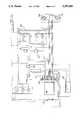
- FIG. 3is a diagram of a closed loop hydraulic system of an embodiment of the present invention.
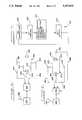
- FIG. 4is a schematic diagram of a control system for a second preferred embodiment of the present invention.
- FIG. 5is a schematic of a portion of the second preferred embodiment of the liftcrane control and hydraulic system relating to swing operation.
- FIG. 6is a schematic of a portion of the second preferred embodiment of the liftcrane control and hydraulic system relating to hoist operation.
- FIG. 7is a flow chart of the routine that may be run on the programmable controller of the second preferred embodiment of the present invention of FIG. 4.
- FIG. 1depicts a flow chart of an embodiment of an improved control system for a liftcrane.
- the various mechanical subsystems 10 of the liftcraneinclude pumps and actuators for the front hoist, rear hoist (whip), swing, boom, and left and right crawlers.
- mechanical subsystemsinclude those which may be characterized strictly as mechanical, e.g. booms, as well as others subsystems such as electrical gauges and video, but not limited to these).
- the mechanical subsystems 10are under the control of an operator who occupies a position in the cab in the upper works of the liftcrane.
- operator controls 12used for operation and control of the mechanical systems of the liftcrane.
- These operator controls 12can be of various types such as switches, shifting levers etc., but can readily be divided into switch-type controls 14 (digital, ON/OFF) and variable controls 15 (analog or infinite position).
- the switch-type controls 14are used for on/off type activities, such as setting a brake, whereas the variable controls 15 are used for activities such as positioning the boom, hoists, or swing.
- the operator controls 12include a mode selector 18 whose function is to tailor the operation of the liftcrane for specific type of activities, as explained below.
- the mode selector 18is considered to be a digital device even though there may be more than two modes available).
- the mode selection switch 18includes selections for main hydraulic mode, counterweight handling mode, crawler extension mode, high speed mode, clamshell mode and free-fall mode. Some of these modes are exclusive of others (such as main hydraulic and free-fall) where their functions are clearly incompatible; otherwise these modes may be combined.
- the outputs of the operator controls 12are directed to a controller 20 and specifically to an interface 22 of the controller 20.
- the interface 22receives signals 24 from each of the variable controls 15 and signals 26 and 27 from each of the switch-type controls 14 and the mode selector 18, respectively.
- the interface 22in turn is connected to a CPU (central processing unit) 28.
- the interface 22handles the signals 24, 26, and 27 in a similar manner.
- the controller 20may be a unit such as the model IHC (Intelligent Hydraulic Controller) manufactured by Hydro Electronic Devices Corporation.
- the CPU 28may be an Intel 8052.
- the controller 20should be designed for heavy duty service under the conditions associated with outdoor construction activity.
- the CPU 28runs a routine which recognizes and interprets the commands from the operator (via the operator control 12) and outputs information back through the interface 22 directing the mechanical subsystems 10 to function in accordance with the operator's instructions. Movements, positions and other information about the mechanical subsystems 10 are monitored by sensors 30 which include both analog sensors 32 and switch-type sensors 34. Information from the sensors 30 is fed back to the interface 22 and in turn to the CPU 28. This information about the mechanical subsystems 10 provided by the sensors 30 is used by the routine running on the CPU 28 to determine if the liftcrane is operating properly.
- the present inventionprovides significant advantages through the use of the controller 20. As mentioned above, high levels of skill and concentration are required of liftcrane operators to coordinate various liftcrane controls to perform even routine operations. Also, some liftcrane operations have to be performed very slowly to ensure safety. These operations can be very fatiguing and tedious. Through the use of the routine provided by the control system and running on the CPU 28, various complicated maneuvers can be simplified or improved.
- Mode selectionrefers to tailoring the operation of the liftcrane for the particular task being performed.
- the mode selector 18is set by the operator to change the way that the crane operates.
- the change in modeis carried out by the routine on CPU 28.
- various of the operator controls 12 in the cabfunction in distinctly different ways and even control different mechanical subsystems in order that the controls are specifically suited to the task to be accomplished.
- the routinecan establish certain functional relationships between several separate mechanical subsystems for particular liftcrane activities (such as dragline or clamshell operations). Previously, such operations required sometimes difficult simultaneous coordination of several different controls by the operator.
- variable controls 15can be set for either fine, precise, small-scale movements or for large-scale movements of the corresponding mechanical subsystems. Thus fewer and simpler controls may be needed in
- this embodiment of the inventionimproves liftcrane operation is in ease of maintenance and trouble-shooting.
- a mechaniccan obtain information on all the mechanical subsystems of the liftcrane by connecting a computer (such as a laptop personal computer) to the controller and downloading the sensor data.
- trouble-shootingcould be accomplished by inputting specific control data directly to the controller, measuring the resultant sensor data, and comparing this to the expected sensor data.
- FIG. 2there is depicted a flow chart of the liftcrane operating routine 48 of an embodiment the present invention.
- This routineis stored in the controller and may be stored in CPU 28.
- the routine 48is stored in EPROM, although other media for storage may be used.
- the source code for this routine in this first embodimentis set out in Appendix I.
- This routine set forth in Appendix Iis specifically tailored for liftcrane standards in the Netherlands and includes provisions specifically directed to the safety standards there. However, the routine may also be used in the United States and in other countries or could easily be modified following the principles set out herein.
- the liftcrane operating routine 48is intended to run continuously on the CPU 28 (in FIG. 1) in a loop fashion.
- the liftcrane operating routine 48 on the CPUreads information provided from the interface 22 (in FIG. 1) which appears as data accessible to the routine at certain addresses.
- Output commands from the liftcrane operating routine 48are transmitted from the CPU 28 to the interface 22 and there are converted to signals in the form required to operate the various mechanical subsystems.
- the liftcrane operating routine 48when the liftcrane is initially turned on (or if the routine reboots itself or restores itself due to a transient fault), the liftcrane operating routine 48 includes an initialization subroutine 50 that initializes variables and reads certain parameters. Following this, an operating mode subroutine 52 reads data indicating which operating mode has been selected by the operator for the liftcrane. Next, a charge pressure reset/out of range subroutine 54 checks to determine if the hydraulic pressure in the liftcrane is in a proper operating range. Following this is a director subroutine 56 which is the main subroutine for the operation of the crane. From the director subroutine 56 the program branches into one of five subroutines associated with operation of the major mechanical subsystems.
- subroutinescontrol the function of the major mechanical subsystems with which they are associated: front hoist drum subroutine 58, rear hoist drum subroutine 60, boom hoist drum subroutine 62, right track subroutine 64, and left track subroutine 66.
- front hoist drum subroutine 58rear hoist drum subroutine 60
- boom hoist drum subroutine 62right track subroutine 64
- left track subroutine 66left track subroutine 66.
- the liftcrane operating routine 48returns to the operating mode subroutine 52 and the starts all over again.
- changes made by the operator at the controlswill be read by the liftcrane operating routine and changes in the operation of mechanical systems will follow.
- subroutines for swing supply and track supplythat are run from the charge pressure reset/out-of-range subroutine 54.
- a counterweight handling subroutine 74branches from the director subroutine 56.
- a swing subroutine 76also branches from the director subroutine 54. The swing subroutine 76 is called during each cycle of the director subroutine 54 to enhance a smooth movement of the swing.
- a watchdog chipmay be provided in controller 20 so that in the event of a failure of the operating routine, the CPU will reboot itself and start the initialization process 50 again.
- the liftcrane operating routine 48can be augmented or modified.
- additional subroutinescan be provided for new operating modes.
- One exampleis a level-luffing operating mode.
- Level-luffingrefers to horizontal movement of a load. This involves both movement of the boom and simultaneous movement of the load hoist. This procedure requires a high degree of skill on the part of the operator and it is often performed when moving loads across horizontal surfaces such as floors. Movement of loads horizontally is often required in liftcrane operation, but can be very difficult to do where it may be required to move the load out of sight of the liftcrane operator.
- load level-luffingcan be precisely and easily provided.
- Still another example of a type of a subroutine that can be provided by the control system of the present inventionis operation playback.
- the controllercan provide that once an operator performs a certain operation or activity, regardless of how complicated it is, the operation can be recorded and "learned" by the routine on the CPU 28. Then the same activity can be played back by the operator and performed over and over again, thereby eliminating some of the tedium and difficulty of the operation.
- another subroutine that can be addedwould be an area avoidance subroutine.
- the liftcrane operatorcan provide information via the control panel indicating areas prohibited to the movement of the liftcrane.
- the liftcrane operating subroutinewould then completely prevent any liftcrane movements that might impinge on the prohibited area thereby highly enhancing the safety of the liftcrane operation. This could be accomplished by having the liftcrane operator first move the crane to a boundary in one direction and indicate by the control panel that this is a first boundary, and then move the crane through non-prohibited area to a second boundary and indicate by the control panel that this is a second boundary. These boundary positions would be recorded by sensors and stored as data in the operating routine. Thereafter, during each cycle of the operating routine, the routine would check the crane movement against the boundaries of the prohibited area and refuse to execute any command that would cause the crane to encroach on the prohibited area.
- Another subroutinecan provide for use of a counterbalancing system.
- a counterbalancing systemis described in copending U.S. application Ser. No. 07/269,222, entitled “Crane And Lift Enhancing Beam Attachment With Movable Counterweight", filed Nov. 9, 1988,U.S. Pat. No. 4,953,722 and incorporated herein by reference.
- Another advantage of the present inventionis that the operation and safety features of the liftcrane can easily be adapted for the different requirements of different countries. For example, in the Netherlands an exterior warning light must be provided when the liftcrane is in the free-fall mode. This can readily be provided by the routine by the addition of several lines of code (refer to Appendix I, lines 2000 to 2095).
- control system of this embodimentfinds particular advantage when used in conjunction with the closed loop hydraulic system of this embodiment of the invention.
- Most liftcranesuse an open loop system which have the inherent disadvantages, as mentioned above.
- This embodimentuses a closed loop hydraulic system operating under the programmable control system.
- the engine 80can produce 210 horsepower.
- the engine sizeis chosen to be suitable for the size the liftcrane which in this case is rated at 50 tons. For different sizes of liftcranes, different sizes of engines would be used.
- the engine 80drives a plurality of main pumps 82.
- main pumps 82there are six main pumps, each associated with one of the major mechanical subsystems of the liftcrane.
- Each of the pumpsdrives an actuator (motor) associated with its mechanical subsystem.
- Each of the six actuatorsis connected to its corresponding pump by a pair of hydraulic lines to form the closed loop. This enables application of hydraulic force to the actuators in either direction.
- a reservoir 102is connected to the engine 80 outside of the closed loops between the pumps 82 and the six mechanical subsystems.
- the actuators in the major mechanical subsystemsinclude the following: A swing motor 104 controls the swing (movement of the upper works in relation to the lower works). A boom hoist motor 105 raises and lowers the boom. A rear hoist motor 106 controls the rear hoist drum and the front hoist motor 107 controls the front hoist drum. A left and right crawler motors 108 and 110 control the tractor crawlers, respectively. Additional mechanical subsystems may be powered either by use of an auxiliary pump, such as a fan pilot pressure pump 130, or by diverting flow from one or more of the main hydraulic pumps. This embodiment uses this former method to power the crawler extenders and gantry. These mechanical subsystems are connected to actuators associated with them by a solenoid valve 134.
- the diverting valve assembly 150operates to combine the closed loops of two or more pumps with a single actuator so that the operation of the mechanical subsystem associated with the actuator can take advantage of more than just the single pump normally associated with it. Consequently, the closed loop hydraulic system of the present invention is able to duplicate performance of an open loop system while also providing the advantages of the closed loop system.
- the diverting valve assembly 150provides the ability to direct a large percentage of the liftcrane's total pumping capacity to either the main or the whip hoist.
- the diverting valve assembly 150also provides the ability to direct a substantial percentage of the liftcrane's total pumping capability to several of the auxiliary mechanical subsystems.
- the diverting valve assembly 150also has the ability to combine several of the pumps to provide charge or pilot flow sufficient to operate large cylinders.
- the ability to operate the diverting valve assembly 150 in the manner describedis facilitated by this embodiment.
- the operation of the diverting valve assembly 150 to meet or exceed the levels of performance associated with an open loop systemis provided by the routine described herein.
- the present embodimentcan provide a high level of performance combined with economy and efficiency.
- the present embodimentprovides new features to augment an operator's skill and efficiency and also can provide a higher level of safety heretofore unavailable in liftcranes.
- FIG. 4there is depicted a schematic diagram of a control system for a second preferred embodiment of the present invention.
- a set of liftcrane mechanical subsystems 200may be operated by a set of operator controls 202 located in an operator's cab 203.
- the set of operator controls 202includes analog controls 206, digital controls 208, and mode selection controls 210.
- the set of operator controls 202is connected to a programmable controller 212 which includes a CPU 214 capable of running an operating routine for the operation of the liftcrane mechanical systems.
- the analog controls 206 and the digital controls 208are connected to an interface 218 to transfer information about the desired operation from the set 202 of operator controls to the CPU 214.
- sensors 222 associated with the set 200 of mechanical subsystemsmonitor the status thereof and provide information back to programmable controller 212.
- the sensors 222include both analog sensors 224 that connect to the programmable controller 212 via the interface 218 to monitor a set 225 of mechanical subsystems, and limit switches 226 that connect to the programmable controller 212 via the interface 218 to monitor another set 227 of mechanical subsystems.
- the analog sensors 224include both pressure transducers 228 and position-speed sensors 230.
- the pressure transducers 228 and position-speed sensors 230may be used to monitor separate sets 231 and 232, respectively, of mechanical subsystems or, for certain mechanical subsystems, the pressure transducers 228 and position-speed sensors 230 may be used in conjunction with a single mechanical subsystem to augment the control and performance thereof.
- mechanical subsystems monitored by pressure sensors and position-speed sensorsneed not necessarily be separate mechanical subsytems).
- Mechanical subsystems that may utilize both pressure sensors and position-speed sensorsinclude the swing and each of the hoists.
- the second preferred embodimentallows for improved liftcrane operation over the previous embodiment in which only position-speed sensors are used.
- the second preferred embodimentprovides for improved liftcrane operation by having the capability to combine, either simultaneously or alternately, both pressure control as well as position-speed control in performing certain functions. This is particularly useful for example for any liftcrane function in which two or more lines are used together. This would include functions such as clamshell, pile driving, tagline, magnet and grapple.
- improved, smoother swing operationis provided by having pressure sensors that provide output signals to the programmable controller.
- the pump associated with the swingcan be operated to maintain a commanded pressure (i.e. "torque output").
- torque outputi.e. "torque output”
- FIG. 5there is depicted a schematic of one embodiment of a portion of the liftcrane control and hydraulic system for the swing.
- a control handle 234is located in the operator's cab.
- the control handle 234includes a lever 236 movable across a range of positions.
- the control handle 234is a part of the operator controls and accordingly the control handle 234 provides an output 235 to the programmable controller 212.
- a swing motor 238is connected to the upper works and lower works (neither shown) to effect the relative movement therebetween.
- the swing motor 238is driven by a pump 240 to which it is connected by first and second hydraulic lines 242 and 244 (i.e. a closed loop 246).
- Two pressure sensorsare associated with the swing motor 238. These pressure sensors are preferably pressure transducers.
- a first pressure sensor 248is connected to the first hydraulic line 242 and a second pressure sensor 250 is connected to the second hydraulic line 244.
- the first and second pressure sensors 248 and 250are connected to the programmable controller 212 to provide feedback signals 252 and 254 thereto indicative of the pressure on each side of the closed loop 246 connected to the swing motor 238.
- the routine run on the programmable controller 212compares these feedback signals with the signal 235 obtained from the control handle 234.
- the routine on the programmable controllerthen generates an output 256 to the pump 240 to modify the operation of the pump, if necessary to effect the desired operation of the swing.
- this same pumpcan be operated instead with displacement-type operating characteristics. Selection of torque- or displacement-type operating characteristics can be made by the operator by means of a mode selection switch in the cab.
- the feedback signals 252 and 254are either not taken into account or factored down and the pump 240 is operated directly in response to the input signal 235 from the control handle 234.
- this operation of the swing in displacement modedoes not provide for free coast, it may be more suitable for certain operations such as precise, small-displacement movements of the swing.
- the pumpcan be operated in either mode depending on what is most suitable for the task.
- the programmable controller 212allows for the switching from torque control to displacement control at the touch of a button.
- a control handle 260is located in the operator's cab.
- the control handle 260includes a lever 262 movable across an infinite range of positions.
- the control handle 260is a part of the operator controls and accordingly the control handle 260 provides an output 264 to the programmable controller 212.
- a hoist motor 266is connected to the hoist drum (not shown) to effect the operation thereof.
- the hoist motor 266is driven by a pump 268 to which it is connected by first and second hydraulic lines 270 and 272 (i.e. a closed loop 274).
- Two pressure sensorsare associated with the hoist motor 266.
- a first pressure sensor 276is connected to the first hydraulic line 270 and a second pressure sensor 278 is connected to the second hydraulic line 272.
- the first and second pressure sensors 276 and 278are connected to the programmable controller 212 to provide first and second pressure feedback signals 280 and 282 to the programmable controller 212 indicative of the pressure on each side of the closed loop 274 connected to the hoist motor 266.
- a position-speed sensor 284is responsive the movement of the hoist.
- the position-speed sensor 284is connected to the programmable controller 212 to provide a feedback signal 286 thereto, indicative of the movement or position of the hoist.
- the routine on the programmable controller 212compares the three feedback signals 280, 282, 286 and the signal 264 obtained from the control handle 260.
- the routinethen generates an output 288 to the pump 268 to modify the operation of the pump, if necessary, to effect the desired operation of the hoist.
- the programmable controller 212can operate the hoist to synchronize brake release and pump displacement at the onset of a hoist or a lower command. This enables clam operation, for instance, to be performed with a "single stick".
- the liftcrane operating routine run on the controllerincludes the following steps:
- the operator in the cabmanipulates the controls to hoist the load and set the brake. Operation of the appropriate controls by the operator sends signals from the controls to the programmable controller.
- the operation of the mechanical subsystems related to the hoist and brakeare under the control of the programmable controller that carries out these operations.
- datais stored in memory indicative of a reading of the pressure sensors 276 and 278 connected to the hoist drum motor 266 at the time when the brake is engaged. This data reading is stored while the brake is engaged including during the time when the brake is engaged and the load is being moved laterally by the swing or by movement of the boom.
- the pressure previously applied to the hoist motor 266dissipates.
- the pressure reading stored in memoryis compared to the pressure reading sensed at the hoist motor 266 by the operating routine on the programmable controller. If the pressure reading at the hoist is not equal to the reading stored in memory, the programmable controller, following the operating rountine, commands pressure to be applied to the hoist motor 266 to duplicate the pressure that was applied thereto immediately at the time the brake was engaged.
- the brakeis disengaged.
- the second preferred embodimentalso includes a direct connection 290 between a set 292 of operator controls and a set 294 of mechanical subsystems to enable this set of mechanical subsystems to be operated directly by the operator controls 292 instead of being operated through the programmable controller 212.
- the mechanical subsystemswhich may be operated outside the control of the programmable controller include the boom pawl and the right and left and front and rear diverting valves. These mechanical subsystems are operated directly instead of through the programmable controller because their operation is not considered to be specifically enhanced or benefitted by computer control. The selection of mechanical subsystems operated directly may be made depending upon considerations associated with the specific use of the liftcrane.
- switches associated with their operationmay be connected to the programmable computer 212 to provide an output 296 thereto in order to provide an indication of the operation of one or more of this set 292 of mechanical subsystems.
- a remote control panel 300is also included.
- the remote control panel 300is connected to the liftcrane by a tether cable (not shown) so that certain of the mechanical subsystems of the liftcrane can be controlled remotely, e.g. by an operator standing outside of the cab.
- the tetheris disconnectable from the liftcrane so that the remote control panel 300 can be removed when not in use, if desired.
- the remote control panel 300may be used to operate certain mechanical subsystems through the programmable controller 212 and also operate certain other functions directly. Accordingly, the remote control panel 300 is connected both to the programmable controller 212 by a line 304 as well as to a set 302 of mechanical subsystems.
- the mechanical subsystems that can be controlled directly by the remote control panelinclude the crawler extension, part of the gantry raising system, and the counterweight pins.
- the mechanical subsystems controlled by the remote control panel through the programmable controllerinclude the boom hoist, movable counterweight and carrier and the movable counterweight beam, as disclosed in the aforementioned co-pending application, Ser. No. 07/269,222, U.S. Pat. No. 4,953,722 incorporated herein by reference.
- the selection of which mechanical subsystems are operated by the remote control panel through the programmable controllerdepends on the specific design of the liftcrane manufacturer with a consideration of the purposes for which the liftcrane will used.
- the second preferred embodimentalso includes an operator's display system connected to the programmable controller.
- An operator's display 310is positioned in the cab 203 and conveys to the operator information about the status of the liftcrane mechanical subsystems.
- the display 310can be a monitor of the CRT or LCD type, or the like, selected for heavy duty use.
- the display 310is capable of presenting information from any of the sensors or operator controls 202 which are connected to the programmable controller 212.
- the display 212can show to the operator air pressure, charge pressure, engine oil pressure, main hydraulic system pressure, fuel level, battery voltage, engine water temperature, engine speed, hoist drum speed, etc.
- routine 318that may be run on the programmable controller 212 of the second preferred embodiment of the present invention.
- the routine 318is similar to the routine 48 of the previous embodiment.
- the routine 318 of the second embodimentincludes sections of code for reading the data from the operator controls 202 and the sensors 222 and outputting commands for the mechanical systems 200.
- the routine of the second embodimentincludes a CALL MACHINE subroutine 320 that calls the SET COMMANDS section 322 which in turn calls the REVISE COMMANDS section 324 that in turn calls a SET OUTPUTS section 326.
- the SET OUTPUTS section 326returns control to the CALL MACHINE section 320 so that the routine operates in a loop and runs each of these sections in each cycle of the loop.
- the CALL MACHINE subroutineis written in Basic and the other three sections are written in machine code.
- a copy of the routine of the second embodimentis included in Appendix II.
Landscapes
- Engineering & Computer Science (AREA)
- Automation & Control Theory (AREA)
- Mechanical Engineering (AREA)
- Control And Safety Of Cranes (AREA)
- Jib Cranes (AREA)
- Forklifts And Lifting Vehicles (AREA)
Abstract
Description
Claims (23)
Priority Applications (12)
| Application Number | Priority Date | Filing Date | Title |
|---|---|---|---|
| US07/566,751US5297019A (en) | 1989-10-10 | 1990-08-13 | Control and hydraulic system for liftcrane |
| EP90310800AEP0422821B1 (en) | 1989-10-10 | 1990-10-03 | Control and hydraulic system for liftcrane |
| AT90310800TATE132465T1 (en) | 1989-10-10 | 1990-10-03 | CONTROL SYSTEM AND HYDRAULIC SYSTEM FOR CRANES |
| DE69024586TDE69024586T2 (en) | 1989-10-10 | 1990-10-03 | Control system and hydraulic system for cranes |
| MX022736AMX172668B (en) | 1989-10-10 | 1990-10-08 | CONTROL SYSTEM FOR THE HANDLING OF A LIFTING CRANE AND IMPROVED METHOD TO CONTROL THE HANDLING OF THE LIFTING CRANE |
| AU63925/90AAU642666B2 (en) | 1989-10-10 | 1990-10-09 | Control and hydraulic system for liftcrane |
| PT95548APT95548B (en) | 1989-10-10 | 1990-10-09 | PROGRAMMABLE CONTROL SYSTEM FOR OPERATING A CRANE, HYDRAULIC SYSTEM FOR THE SAME AND PROCESS FOR THEIR OPERATION |
| CA002027214ACA2027214C (en) | 1989-10-10 | 1990-10-10 | Control and hydraulic system for liftcrane |
| KR1019900016012AKR0150448B1 (en) | 1989-10-10 | 1990-10-10 | Improved control of hydraulic crane and hydraulic system |
| JP2273159AJPH03186597A (en) | 1989-10-10 | 1990-10-11 | Device and method for controlling lift crane operation |
| US08/210,988US5579931A (en) | 1989-10-10 | 1994-03-18 | Liftcrane with synchronous rope operation |
| US08/748,986US6758356B1 (en) | 1989-10-10 | 1996-11-14 | Liftcrane with synchronous rope operation |
Applications Claiming Priority (2)
| Application Number | Priority Date | Filing Date | Title |
|---|---|---|---|
| US07/418,879US5189605A (en) | 1989-10-10 | 1989-10-10 | Control and hydraulic system for a liftcrane |
| US07/566,751US5297019A (en) | 1989-10-10 | 1990-08-13 | Control and hydraulic system for liftcrane |
Related Parent Applications (1)
| Application Number | Title | Priority Date | Filing Date |
|---|---|---|---|
| US07/418,879Continuation-In-PartUS5189605A (en) | 1989-10-10 | 1989-10-10 | Control and hydraulic system for a liftcrane |
Related Child Applications (1)
| Application Number | Title | Priority Date | Filing Date |
|---|---|---|---|
| US08/210,988Continuation-In-PartUS5579931A (en) | 1989-10-10 | 1994-03-18 | Liftcrane with synchronous rope operation |
Publications (1)
| Publication Number | Publication Date |
|---|---|
| US5297019Atrue US5297019A (en) | 1994-03-22 |
Family
ID=27024289
Family Applications (1)
| Application Number | Title | Priority Date | Filing Date |
|---|---|---|---|
| US07/566,751Expired - LifetimeUS5297019A (en) | 1989-10-10 | 1990-08-13 | Control and hydraulic system for liftcrane |
Country Status (2)
| Country | Link |
|---|---|
| US (1) | US5297019A (en) |
| KR (1) | KR0150448B1 (en) |
Cited By (34)
| Publication number | Priority date | Publication date | Assignee | Title |
|---|---|---|---|---|
| US5509220A (en)* | 1994-07-29 | 1996-04-23 | Vermeer Manufacturing Company | Track trencher propulsion system and process |
| US5544055A (en)* | 1994-07-29 | 1996-08-06 | Vermeer Manufacturing Company | Track trencher control system and process |
| US5574642A (en)* | 1994-07-29 | 1996-11-12 | Vermeer Manufacturing Company | Track trencher information system and process |
| US5579931A (en)* | 1989-10-10 | 1996-12-03 | Manitowoc Engineering Company | Liftcrane with synchronous rope operation |
| US5590041A (en)* | 1994-07-29 | 1996-12-31 | Vermeer Manufacturing Company | Track trencher steering system and process |
| US5704141A (en)* | 1992-11-09 | 1998-01-06 | Kubota Corporation | Contact prevention system for a backhoe |
| EP0945393A2 (en) | 1998-03-27 | 1999-09-29 | Manitowoc Crane Group, Inc. | Four track crawler crane |
| US5963445A (en)* | 1995-11-21 | 1999-10-05 | Vdo Adolf Schindling Ag | Method for the production of actuator signals |
| US6062405A (en)* | 1996-04-26 | 2000-05-16 | Manitowoc Crane Group, Inc. | Hydraulic boom hoist cylinder crane |
| US6079576A (en)* | 1995-12-13 | 2000-06-27 | Liebherr-Werk Ehingen Gmbh | Control device for a hoist mechanism of a crane |
| US6134815A (en)* | 1998-02-18 | 2000-10-24 | Rohr Gmbh | Monitoring device for motor-driven underwater grab bucket dredge gear |
| US6269635B1 (en) | 1999-01-20 | 2001-08-07 | Manitowoc Crane Group, Inc. | Control and hydraulic system for a liftcrane |
| US6481202B1 (en) | 1997-04-16 | 2002-11-19 | Manitowoc Crane Companies, Inc. | Hydraulic system for boom hoist cylinder crane |
| US6758356B1 (en) | 1989-10-10 | 2004-07-06 | Manitowoc Crane Companies, Inc. | Liftcrane with synchronous rope operation |
| US20040188094A1 (en)* | 2003-03-24 | 2004-09-30 | Michael Piecyk | Wireline subsea metering head and method of use |
| US20070012010A1 (en)* | 2005-07-14 | 2007-01-18 | Otto Douglas R | Method and apparatus for controlling a windrower header flotation system during removal of the header |
| US20080019815A1 (en)* | 2005-10-05 | 2008-01-24 | Oshkosh Truck Corporation | System for monitoring load and angle for mobile lift device |
| US20080038106A1 (en)* | 2005-10-05 | 2008-02-14 | Oshkosh Truck Corporation | Mobile lift device |
| US7367464B1 (en) | 2007-01-30 | 2008-05-06 | The United States Of America As Represented By The Secretary Of The Navy | Pendulation control system with active rider block tagline system for shipboard cranes |
| US7416169B2 (en) | 2004-08-02 | 2008-08-26 | Terex Demag Gmbh | Hoisting-cable drive comprising a single bottom-hook block and two winches |
| US20090000157A1 (en)* | 2007-06-29 | 2009-01-01 | Ty Hartwick | Track Trencher Propulsion System with Component Feedback |
| US20090000156A1 (en)* | 2007-06-29 | 2009-01-01 | Ty Hartwick | Track Trencher Propulsion System with Load Control |
| US20090000154A1 (en)* | 2007-06-29 | 2009-01-01 | Ty Hartwick | Trencher with Auto-Plunge and Boom Depth Control |
| US20090055039A1 (en)* | 2007-08-23 | 2009-02-26 | Edw. C. Levy Co. | Method and Apparatus for Providing Diagnostics of a Lifting Magnet System |
| US20090229261A1 (en)* | 2008-03-17 | 2009-09-17 | Caterpillar Inc. | Dual mode hydraulic circuit control and method |
| US20100257757A1 (en)* | 2009-04-09 | 2010-10-14 | Vermeer Manufacturing Company | Machine attachment based speed control system |
| US20110251746A1 (en)* | 2008-11-10 | 2011-10-13 | Sumitomo(S.H.I) Construction Machinery Co., Ltd. | Hybrid-type construction machine |
| US8195368B1 (en) | 2008-11-07 | 2012-06-05 | The United States Of America As Represented By The Secretary Of The Navy | Coordinated control of two shipboard cranes for cargo transfer with ship motion compensation |
| US20130205762A1 (en)* | 2011-11-29 | 2013-08-15 | Vanguard Equipment, Inc. | Auxiliary flow valve system and method for managing load flow requirements for auxiliary functions on a tractor hydraulic system |
| CN103723632A (en)* | 2013-12-13 | 2014-04-16 | 中联重科股份有限公司 | Crane rotation control method, crane rotation control system and crane |
| US20140311138A1 (en)* | 2013-04-22 | 2014-10-23 | Illinois Tool Works Inc. | Systems and methods for detecting a type of hydraulic device |
| US9302890B1 (en)* | 2013-04-29 | 2016-04-05 | TNV, Inc. | Crane control system and method |
| US20180179029A1 (en)* | 2014-12-23 | 2018-06-28 | Manitowoc Crane Companies, Llc | Crane 3d workspace spatial techniques for crane operation in proximity of obstacles |
| CN116081468A (en)* | 2022-11-05 | 2023-05-09 | 浙江麒龙起重机械有限公司 | Pipe pile production line unmanned crane collaborative system |
Families Citing this family (2)
| Publication number | Priority date | Publication date | Assignee | Title |
|---|---|---|---|---|
| DE19521421C2 (en)* | 1995-06-14 | 1999-12-30 | Hoffmeister Helmut | Controllable inclined elevator |
| KR101663585B1 (en) | 2016-02-24 | 2016-10-10 | 서원대학교산학협력단 | Access management system for enterprise informtaion system using Big-data analysis based on work action and method thereof |
Citations (22)
| Publication number | Priority date | Publication date | Assignee | Title |
|---|---|---|---|---|
| FR2121549A1 (en)* | 1971-01-04 | 1972-08-25 | Gs Equipment Cy | |
| US3851766A (en)* | 1971-10-21 | 1974-12-03 | G S Equipment Co | Programmable hydraulic drive system for transporting articles |
| US4178591A (en)* | 1978-06-21 | 1979-12-11 | Eaton Corporation | Crane operating aid with operator interaction |
| US4185280A (en)* | 1976-12-31 | 1980-01-22 | Kruger & Co. Kg | Method of and apparatus for monitoring or controlling the operation of a boom-type crane or the like |
| US4268013A (en)* | 1978-06-12 | 1981-05-19 | Nl Industries, Inc. | Crane motion compensator |
| DE3115471A1 (en)* | 1981-04-16 | 1982-10-28 | Gabler Gmbh & Co Kg, 4230 Wesel | TURN TOWERS |
| EP0076485A1 (en)* | 1981-10-02 | 1983-04-13 | Hitachi Construction Machinery Co., Ltd. | Control system for hydraulic circuit apparatus |
| US4489551A (en)* | 1983-01-19 | 1984-12-25 | Hitachi Construction Machinery Co., Ltd. | Failure detection system for hydraulic pump |
| US4510750A (en)* | 1980-06-04 | 1985-04-16 | Hitachi Construction Machinery Co., Ltd. | Circuit pressure control system for hydrostatic power transmission |
| US4514796A (en)* | 1982-09-08 | 1985-04-30 | Joy Manufacturing Company | Method and apparatus for controlling the position of a hydraulic boom |
| US4532595A (en)* | 1982-12-02 | 1985-07-30 | Kruger Gmbh & Co. Kg | Load-monitoring system for boom-type crane |
| DE3611553C1 (en)* | 1986-04-07 | 1987-07-23 | Orenstein & Koppel Ag | Arrangement for operating a diesel-hydraulic drive |
| EP0253657A2 (en)* | 1986-07-15 | 1988-01-20 | Honda Giken Kogyo Kabushiki Kaisha | Method of controlling continuously variable automotive transmission |
| US4782662A (en)* | 1984-09-27 | 1988-11-08 | National-Oilwell | Boom crane centering |
| US4815614A (en)* | 1986-06-19 | 1989-03-28 | Ari Putkonen | Control system for a crane |
| EP0364994A1 (en)* | 1988-10-19 | 1990-04-25 | Man Ghh Krantechnik Gmbh | Crane control |
| US4945472A (en)* | 1987-09-30 | 1990-07-31 | Mitsubihsi Denki Kabushiki Kaisha | Data processor with I/O area detection |
| US4953723A (en)* | 1989-04-21 | 1990-09-04 | Kabushiki Kaisha Kobe Seiko Sho | Apparatus for suppressing quaky movements of mobile cranes |
| US4969562A (en)* | 1989-04-21 | 1990-11-13 | Kabushiki Kaisha Kobe Seiko Sho | Apparatus for suppressing quaky movements of mobile type crane |
| US5029067A (en)* | 1987-01-30 | 1991-07-02 | Kabushiki Kaisha Komatsu Seisakusho | Operation control device |
| US5034892A (en)* | 1989-05-10 | 1991-07-23 | Kabushiki Kaisha Kobe Seiko Sho | Apparatus for suppressing vibratory or quaky movements of mobile type crane |
| US5160056A (en)* | 1989-09-27 | 1992-11-03 | Kabushiki Kaisha Kobe Seiko Sho | Safety device for crane |
- 1990
- 1990-08-13USUS07/566,751patent/US5297019A/ennot_activeExpired - Lifetime
- 1990-10-10KRKR1019900016012Apatent/KR0150448B1/ennot_activeExpired - Fee Related
Patent Citations (22)
| Publication number | Priority date | Publication date | Assignee | Title |
|---|---|---|---|---|
| FR2121549A1 (en)* | 1971-01-04 | 1972-08-25 | Gs Equipment Cy | |
| US3851766A (en)* | 1971-10-21 | 1974-12-03 | G S Equipment Co | Programmable hydraulic drive system for transporting articles |
| US4185280A (en)* | 1976-12-31 | 1980-01-22 | Kruger & Co. Kg | Method of and apparatus for monitoring or controlling the operation of a boom-type crane or the like |
| US4268013A (en)* | 1978-06-12 | 1981-05-19 | Nl Industries, Inc. | Crane motion compensator |
| US4178591A (en)* | 1978-06-21 | 1979-12-11 | Eaton Corporation | Crane operating aid with operator interaction |
| US4510750A (en)* | 1980-06-04 | 1985-04-16 | Hitachi Construction Machinery Co., Ltd. | Circuit pressure control system for hydrostatic power transmission |
| DE3115471A1 (en)* | 1981-04-16 | 1982-10-28 | Gabler Gmbh & Co Kg, 4230 Wesel | TURN TOWERS |
| EP0076485A1 (en)* | 1981-10-02 | 1983-04-13 | Hitachi Construction Machinery Co., Ltd. | Control system for hydraulic circuit apparatus |
| US4514796A (en)* | 1982-09-08 | 1985-04-30 | Joy Manufacturing Company | Method and apparatus for controlling the position of a hydraulic boom |
| US4532595A (en)* | 1982-12-02 | 1985-07-30 | Kruger Gmbh & Co. Kg | Load-monitoring system for boom-type crane |
| US4489551A (en)* | 1983-01-19 | 1984-12-25 | Hitachi Construction Machinery Co., Ltd. | Failure detection system for hydraulic pump |
| US4782662A (en)* | 1984-09-27 | 1988-11-08 | National-Oilwell | Boom crane centering |
| DE3611553C1 (en)* | 1986-04-07 | 1987-07-23 | Orenstein & Koppel Ag | Arrangement for operating a diesel-hydraulic drive |
| US4815614A (en)* | 1986-06-19 | 1989-03-28 | Ari Putkonen | Control system for a crane |
| EP0253657A2 (en)* | 1986-07-15 | 1988-01-20 | Honda Giken Kogyo Kabushiki Kaisha | Method of controlling continuously variable automotive transmission |
| US5029067A (en)* | 1987-01-30 | 1991-07-02 | Kabushiki Kaisha Komatsu Seisakusho | Operation control device |
| US4945472A (en)* | 1987-09-30 | 1990-07-31 | Mitsubihsi Denki Kabushiki Kaisha | Data processor with I/O area detection |
| EP0364994A1 (en)* | 1988-10-19 | 1990-04-25 | Man Ghh Krantechnik Gmbh | Crane control |
| US4953723A (en)* | 1989-04-21 | 1990-09-04 | Kabushiki Kaisha Kobe Seiko Sho | Apparatus for suppressing quaky movements of mobile cranes |
| US4969562A (en)* | 1989-04-21 | 1990-11-13 | Kabushiki Kaisha Kobe Seiko Sho | Apparatus for suppressing quaky movements of mobile type crane |
| US5034892A (en)* | 1989-05-10 | 1991-07-23 | Kabushiki Kaisha Kobe Seiko Sho | Apparatus for suppressing vibratory or quaky movements of mobile type crane |
| US5160056A (en)* | 1989-09-27 | 1992-11-03 | Kabushiki Kaisha Kobe Seiko Sho | Safety device for crane |
Non-Patent Citations (2)
| Title |
|---|
| The Liebherr Technical Data Cable Excavator at page 3, column 1. date Oct. 1986.* |
| The Liebherr Technical Description HS 840, HS 850, HS 870. date Apr. 1985.* |
Cited By (54)
| Publication number | Priority date | Publication date | Assignee | Title |
|---|---|---|---|---|
| US5579931A (en)* | 1989-10-10 | 1996-12-03 | Manitowoc Engineering Company | Liftcrane with synchronous rope operation |
| US6758356B1 (en) | 1989-10-10 | 2004-07-06 | Manitowoc Crane Companies, Inc. | Liftcrane with synchronous rope operation |
| US5704141A (en)* | 1992-11-09 | 1998-01-06 | Kubota Corporation | Contact prevention system for a backhoe |
| US5509220A (en)* | 1994-07-29 | 1996-04-23 | Vermeer Manufacturing Company | Track trencher propulsion system and process |
| US5544055A (en)* | 1994-07-29 | 1996-08-06 | Vermeer Manufacturing Company | Track trencher control system and process |
| US5574642A (en)* | 1994-07-29 | 1996-11-12 | Vermeer Manufacturing Company | Track trencher information system and process |
| US5590041A (en)* | 1994-07-29 | 1996-12-31 | Vermeer Manufacturing Company | Track trencher steering system and process |
| US5963445A (en)* | 1995-11-21 | 1999-10-05 | Vdo Adolf Schindling Ag | Method for the production of actuator signals |
| US6079576A (en)* | 1995-12-13 | 2000-06-27 | Liebherr-Werk Ehingen Gmbh | Control device for a hoist mechanism of a crane |
| US6062405A (en)* | 1996-04-26 | 2000-05-16 | Manitowoc Crane Group, Inc. | Hydraulic boom hoist cylinder crane |
| US6481202B1 (en) | 1997-04-16 | 2002-11-19 | Manitowoc Crane Companies, Inc. | Hydraulic system for boom hoist cylinder crane |
| US6134815A (en)* | 1998-02-18 | 2000-10-24 | Rohr Gmbh | Monitoring device for motor-driven underwater grab bucket dredge gear |
| US6588521B1 (en) | 1998-03-27 | 2003-07-08 | Manitowoc Crane Companies, Inc. | Four track crawler crane |
| EP0945393A2 (en) | 1998-03-27 | 1999-09-29 | Manitowoc Crane Group, Inc. | Four track crawler crane |
| US6269635B1 (en) | 1999-01-20 | 2001-08-07 | Manitowoc Crane Group, Inc. | Control and hydraulic system for a liftcrane |
| US7000903B2 (en) | 2003-03-24 | 2006-02-21 | Oceaneering International, Inc. | Wireline subsea metering head and method of use |
| US20040188094A1 (en)* | 2003-03-24 | 2004-09-30 | Michael Piecyk | Wireline subsea metering head and method of use |
| US7416169B2 (en) | 2004-08-02 | 2008-08-26 | Terex Demag Gmbh | Hoisting-cable drive comprising a single bottom-hook block and two winches |
| US20070012010A1 (en)* | 2005-07-14 | 2007-01-18 | Otto Douglas R | Method and apparatus for controlling a windrower header flotation system during removal of the header |
| US7489098B2 (en) | 2005-10-05 | 2009-02-10 | Oshkosh Corporation | System for monitoring load and angle for mobile lift device |
| US20080019815A1 (en)* | 2005-10-05 | 2008-01-24 | Oshkosh Truck Corporation | System for monitoring load and angle for mobile lift device |
| US20080038106A1 (en)* | 2005-10-05 | 2008-02-14 | Oshkosh Truck Corporation | Mobile lift device |
| US7683564B2 (en) | 2005-10-05 | 2010-03-23 | Oshkosh Corporation | System for monitoring load and angle for mobile lift device |
| US7367464B1 (en) | 2007-01-30 | 2008-05-06 | The United States Of America As Represented By The Secretary Of The Navy | Pendulation control system with active rider block tagline system for shipboard cranes |
| US20090000154A1 (en)* | 2007-06-29 | 2009-01-01 | Ty Hartwick | Trencher with Auto-Plunge and Boom Depth Control |
| US20090000156A1 (en)* | 2007-06-29 | 2009-01-01 | Ty Hartwick | Track Trencher Propulsion System with Load Control |
| US20090000157A1 (en)* | 2007-06-29 | 2009-01-01 | Ty Hartwick | Track Trencher Propulsion System with Component Feedback |
| US8042290B2 (en) | 2007-06-29 | 2011-10-25 | Vermeer Manufacturing Company | Trencher with auto-plunge and boom depth control |
| US20110035969A1 (en)* | 2007-06-29 | 2011-02-17 | Vermeer Manufacturing Company | Trencher with Auto-Plunge and Boom Depth Control |
| US7762013B2 (en) | 2007-06-29 | 2010-07-27 | Vermeer Manufacturing Company | Trencher with auto-plunge and boom depth control |
| US7778756B2 (en) | 2007-06-29 | 2010-08-17 | Vermeer Manufacturing Company | Track trencher propulsion system with load control |
| US7930843B2 (en) | 2007-06-29 | 2011-04-26 | Vermeer Manufacturing Company | Track trencher propulsion system with component feedback |
| US20090055039A1 (en)* | 2007-08-23 | 2009-02-26 | Edw. C. Levy Co. | Method and Apparatus for Providing Diagnostics of a Lifting Magnet System |
| US7848861B2 (en) | 2007-08-23 | 2010-12-07 | Edw. C. Levy Co. | Method and apparatus for providing diagnostics of a lifting magnet system |
| US20090229261A1 (en)* | 2008-03-17 | 2009-09-17 | Caterpillar Inc. | Dual mode hydraulic circuit control and method |
| US7874151B2 (en) | 2008-03-17 | 2011-01-25 | Caterpillar Inc | Dual mode hydraulic circuit control and method |
| US8195368B1 (en) | 2008-11-07 | 2012-06-05 | The United States Of America As Represented By The Secretary Of The Navy | Coordinated control of two shipboard cranes for cargo transfer with ship motion compensation |
| US9725008B2 (en)* | 2008-11-10 | 2017-08-08 | Sumitomo Heavy Industries, Ltd. | Hybrid type construction machine |
| US20110251746A1 (en)* | 2008-11-10 | 2011-10-13 | Sumitomo(S.H.I) Construction Machinery Co., Ltd. | Hybrid-type construction machine |
| US10766480B2 (en)* | 2008-11-10 | 2020-09-08 | Sumitomo Heavy Industries, Ltd. | Hybrid construction machine |
| US20170335547A1 (en)* | 2008-11-10 | 2017-11-23 | Sumitomo Heavy Industries, Ltd. | Hybrid construction machine |
| US20100257757A1 (en)* | 2009-04-09 | 2010-10-14 | Vermeer Manufacturing Company | Machine attachment based speed control system |
| US8347529B2 (en) | 2009-04-09 | 2013-01-08 | Vermeer Manufacturing Company | Machine attachment based speed control system |
| US8819966B2 (en) | 2009-04-09 | 2014-09-02 | Vermeer Manufacturing Company | Machine attachment based speed control system |
| US20130205762A1 (en)* | 2011-11-29 | 2013-08-15 | Vanguard Equipment, Inc. | Auxiliary flow valve system and method for managing load flow requirements for auxiliary functions on a tractor hydraulic system |
| US20140311138A1 (en)* | 2013-04-22 | 2014-10-23 | Illinois Tool Works Inc. | Systems and methods for detecting a type of hydraulic device |
| US9835181B2 (en)* | 2013-04-22 | 2017-12-05 | Illinois Tool Works Inc. | Systems and methods for detecting a type of hydraulic device |
| US10001148B2 (en)* | 2013-04-22 | 2018-06-19 | Illinois Tool Works Inc. | Systems and methods for detecting a type of hydraulic device |
| US9302890B1 (en)* | 2013-04-29 | 2016-04-05 | TNV, Inc. | Crane control system and method |
| CN103723632B (en)* | 2013-12-13 | 2016-06-08 | 中联重科股份有限公司 | Crane rotation control method, crane rotation control system and crane |
| CN103723632A (en)* | 2013-12-13 | 2014-04-16 | 中联重科股份有限公司 | Crane rotation control method, crane rotation control system and crane |
| US20180179029A1 (en)* | 2014-12-23 | 2018-06-28 | Manitowoc Crane Companies, Llc | Crane 3d workspace spatial techniques for crane operation in proximity of obstacles |
| US10822208B2 (en)* | 2014-12-23 | 2020-11-03 | Manitowoc Crane Companies, Llc | Crane 3D workspace spatial techniques for crane operation in proximity of obstacles |
| CN116081468A (en)* | 2022-11-05 | 2023-05-09 | 浙江麒龙起重机械有限公司 | Pipe pile production line unmanned crane collaborative system |
Also Published As
| Publication number | Publication date |
|---|---|
| KR910007774A (en) | 1991-05-30 |
| KR0150448B1 (en) | 1998-10-15 |
Similar Documents
| Publication | Publication Date | Title |
|---|---|---|
| US5297019A (en) | Control and hydraulic system for liftcrane | |
| EP0422821B1 (en) | Control and hydraulic system for liftcrane | |
| JP3943185B2 (en) | Hydraulic drive | |
| US6305419B1 (en) | Variable pilot pressure control for pilot valves | |
| US6269635B1 (en) | Control and hydraulic system for a liftcrane | |
| US12209388B2 (en) | System and methods for cycle time management | |
| US10767344B2 (en) | Hydraulic drive control | |
| US4700802A (en) | Material handling vehicle having remote transmission controller | |
| US3978998A (en) | Fast hoist control system | |
| JPH0741287A (en) | Boom derricking and hoisting motion control device of crane | |
| US10934687B2 (en) | Hydraulic power prioritization | |
| JPH0318600A (en) | Electronic oil-pressure boom control apparatus | |
| JPS58204940A (en) | Controller of fuel injection pump in engine | |
| JP4691806B2 (en) | Operation control device for construction machinery | |
| US20240110365A1 (en) | Drive motor displacement control | |
| JP2986510B2 (en) | Swing control device | |
| WO2022256178A1 (en) | System and method for controlling engine operations | |
| JP3939037B2 (en) | Hydraulic drive control device for work equipment | |
| JP2002003154A (en) | Device for setting maximum speed of hydraulic motor of construction machine | |
| JPH02193899A (en) | Hydraulic device in battery type industrial vehicle | |
| JPH10311302A (en) | Hydraulic equipment for cargo handling vehicles | |
| JPH053288U (en) | Control device for vehicle-mounted crane | |
| JPH04321804A (en) | Hydraulic motor control device | |
| JPH10338495A (en) | Safety device of hydraulic work device |
Legal Events
| Date | Code | Title | Description |
|---|---|---|---|
| AS | Assignment | Owner name:MANITOWOC COMPANY, INC., THE, WISCONSIN Free format text:ASSIGNMENT OF ASSIGNORS INTEREST.;ASSIGNOR:ZUEHLKE, ARTHUR G.;REEL/FRAME:005423/0648 Effective date:19900806 | |
| STCF | Information on status: patent grant | Free format text:PATENTED CASE | |
| FEPP | Fee payment procedure | Free format text:PAYOR NUMBER ASSIGNED (ORIGINAL EVENT CODE: ASPN); ENTITY STATUS OF PATENT OWNER: LARGE ENTITY | |
| AS | Assignment | Owner name:MANITOWOC CRANE GROUP, INC., NEVADA Free format text:ASSIGNMENT OF ASSIGNORS INTEREST;ASSIGNOR:MANITOWOC COMPANY, INC., THE;REEL/FRAME:008334/0829 Effective date:19961227 | |
| FPAY | Fee payment | Year of fee payment:4 | |
| RR | Request for reexamination filed | Effective date:20000128 | |
| AS | Assignment | Owner name:MANITOWOC CRANE GROUP, INC, NEVADA Free format text:ASSIGNMENT OF ASSIGNORS INTEREST;ASSIGNORS:ZUEHIKE, ARTHUR G;PECH, DAVID;REEL/FRAME:010756/0707 Effective date:20000417 | |
| FPAY | Fee payment | Year of fee payment:8 | |
| AS | Assignment | Owner name:BANKERS TRUST COMPANY, NEW YORK Free format text:GRANT OF SECURITY INTEREST;ASSIGNOR:MANITOWOC CRANE COMPANIES, INC. (FORMERLY MANITOWOC CRANE GROUP, INC.);REEL/FRAME:012043/0757 Effective date:20010508 | |
| AS | Assignment | Owner name:MANITOWOC CRANE COMPANIES, INC., NEVADA Free format text:CHANGE OF NAME;ASSIGNOR:MANITOWOC CRANE GROUP, INC.;REEL/FRAME:012530/0794 Effective date:20010227 | |
| B1 | Reexamination certificate first reexamination | Free format text:CLAIMS 16, 17 AND 20-23 ARE CANCELLED. CLAIMS 1, 8, 10-14 AND 18 ARE DETERMINED TO BE PATENTABLE AS AMENDED. CLAIMS 2-7, 9, 15 AND 19, DEPENDENT ON AN AMENDED CLAIM, ARE DETERMINED TO BE PATENTABLE. NEW CLAIMS 24-81 ARE ADDED AND DETERMINED TO BE PATENTABLE. | |
| AS | Assignment | Owner name:MANITOWOC CRANE COMPANIES, INC., NEVADA Free format text:PATENT RELEASE OF SECURITY INTEREST;ASSIGNOR:DEUTSCHE BANK TRUST COMPANY AMERICAS (FOERMERLY KNOWN AS BANKERS TRUST COMPANY), AS AGENT;REEL/FRAME:016397/0347 Effective date:20050610 | |
| AS | Assignment | Owner name:JPMORGAN CHASE BANK, N.A., AS AGENT, ILLINOIS Free format text:GRANT OF SECURITY INTEREST IN U.S. PATENTS;ASSIGNOR:MANITOWOC CRANE COMPANIES, INC.;REEL/FRAME:016446/0054 Effective date:20050610 | |
| FPAY | Fee payment | Year of fee payment:12 | |
| AS | Assignment | Owner name:JPMORGAN CHASE BANK, N.A., AS AGENT, ILLINOIS Free format text:SECURITY AGREEMENT;ASSIGNOR:MANITOWOC CRANE COMPANIES, INC.;REEL/FRAME:022399/0530 Effective date:20080414 Owner name:JPMORGAN CHASE BANK, N.A., AS AGENT,ILLINOIS Free format text:SECURITY AGREEMENT;ASSIGNOR:MANITOWOC CRANE COMPANIES, INC.;REEL/FRAME:022399/0530 Effective date:20080414 | |
| AS | Assignment | Owner name:MANITOWOC CRANE COMPANIES, INC., NEVADA Free format text:RELEASE OF SECURITY INTEREST IN U.S. PATENTS;ASSIGNOR:JPMORGAN CHASE BANK, N.A. AS AGENT;REEL/FRAME:022416/0092 Effective date:20081106 | |
| AS | Assignment | Owner name:MANITOWOC CRANE COMPANIES, LLC, WISCONSIN Free format text:RELEASE BY SECURED PARTY;ASSIGNOR:JPMORGAN CHASE BANK, N.A., AS COLLATERAL AGENT;REEL/FRAME:037899/0053 Effective date:20160303 |