US5295658A - Medical coupling site including slit reinforcing members - Google Patents
Medical coupling site including slit reinforcing membersDownload PDFInfo
- Publication number
- US5295658A US5295658AUS08/068,777US6877793AUS5295658AUS 5295658 AUS5295658 AUS 5295658AUS 6877793 AUS6877793 AUS 6877793AUS 5295658 AUS5295658 AUS 5295658A
- Authority
- US
- United States
- Prior art keywords
- slit
- body portion
- diaphragm
- valve element
- ribs
- Prior art date
- Legal status (The legal status is an assumption and is not a legal conclusion. Google has not performed a legal analysis and makes no representation as to the accuracy of the status listed.)
- Expired - Fee Related
Links
Images


Classifications
- F—MECHANICAL ENGINEERING; LIGHTING; HEATING; WEAPONS; BLASTING
- F16—ENGINEERING ELEMENTS AND UNITS; GENERAL MEASURES FOR PRODUCING AND MAINTAINING EFFECTIVE FUNCTIONING OF MACHINES OR INSTALLATIONS; THERMAL INSULATION IN GENERAL
- F16L—PIPES; JOINTS OR FITTINGS FOR PIPES; SUPPORTS FOR PIPES, CABLES OR PROTECTIVE TUBING; MEANS FOR THERMAL INSULATION IN GENERAL
- F16L29/00—Joints with fluid cut-off means
- F16L29/005—Joints with fluid cut-off means joints with cut-off devices which can be perforated
- A—HUMAN NECESSITIES
- A61—MEDICAL OR VETERINARY SCIENCE; HYGIENE
- A61M—DEVICES FOR INTRODUCING MEDIA INTO, OR ONTO, THE BODY; DEVICES FOR TRANSDUCING BODY MEDIA OR FOR TAKING MEDIA FROM THE BODY; DEVICES FOR PRODUCING OR ENDING SLEEP OR STUPOR
- A61M39/00—Tubes, tube connectors, tube couplings, valves, access sites or the like, specially adapted for medical use
- A61M39/02—Access sites
- A61M39/04—Access sites having pierceable self-sealing members
- A61M39/045—Access sites having pierceable self-sealing members pre-slit to be pierced by blunt instrument
- Y—GENERAL TAGGING OF NEW TECHNOLOGICAL DEVELOPMENTS; GENERAL TAGGING OF CROSS-SECTIONAL TECHNOLOGIES SPANNING OVER SEVERAL SECTIONS OF THE IPC; TECHNICAL SUBJECTS COVERED BY FORMER USPC CROSS-REFERENCE ART COLLECTIONS [XRACs] AND DIGESTS
- Y10—TECHNICAL SUBJECTS COVERED BY FORMER USPC
- Y10S—TECHNICAL SUBJECTS COVERED BY FORMER USPC CROSS-REFERENCE ART COLLECTIONS [XRACs] AND DIGESTS
- Y10S604/00—Surgery
- Y10S604/905—Aseptic connectors or couplings, e.g. frangible, piercable
Definitions
- the present inventionrelates to a coupling site for use in medical applications and more particularly, to a coupling site which includes a valve element and support structure for cooperation with a standard male luer lock having a male luer taper and a threaded locking collar.
- needle type injection siteshave the advantages of providing quick access for a fluid cannula as well as providing an access site which ensures a fluid-tight seal due to the small size of the aperture formed in the diaphragm by the needle.
- One proposed solution for eliminating needles at coupling sitesincludes providing a valve member having a slit for receiving a blunt cannula therethrough wherein the slit is biased to a closed position such that a fluid-tight seal is formed at the valve member when the cannula is removed.
- U.S. Pat. No. 4,765,588 to Atkinsondiscloses a valve for receiving the blunt end of a syringe and includes a slit diaphragm member mounted within a tubular body wherein the diaphragm is stretched in the area of the slit and moves in close to the tubular body as a luer taper portion of the syringe is inserted.
- the exterior wall of the body portionis dimensioned to be received within a threaded locking collar of the syringe surrounding the luer taper whereby an additional fluid-tight seal is formed with the valve.
- One such special cannulacontemplates providing a female luer connection for threadably engaging within the threaded locking collar of a male luer lock fitting on a syringe and further includes a specially configured blunt cannula having a tapered end for passing through the preslit septum of the valve.
- the housing holding the septummay be provided with threads for engaging coupling threads located interiorly of a shield surrounding the cannula.
- the outer diameter of the housingis formed larger than the inner diameter of the threaded collar on the syringe in order to provide sufficient space for the septum which expands outwardly into an annular space during insertion of a cannula.
- a medical coupling sitethat is usable with blunt cannula such as are provided by standard male luer lock fittings having a male luer taper surrounded by a threaded locking collar and in which the site is provided with a valve element and means for directly engaging the threads on the locking collar to form a mechanical connection. It should be noted that such a site is highly desirable in that standard dimensions for both male and female luer taper fittings have been recognized by both the American National Standards Institute, Inc. (ANSI) and by the International Organization for Standardization (ISO).
- ANSIAmerican National Standards Institute, Inc.
- ISOInternational Organization for Standardization
- fittings formed on the ends of syringes, as well as fittings for the majority fluid connections used in medical applications throughout the world, conform to the ANSI and ISO standards and a coupling site incorporating a valve for use with such standard fittingswould provide the advantage of allowing a positive mechanical connection to be formed at the coupling site as well as eliminate the need for the use of needles or special cannula to penetrate the valve element, and thus would overcome disadvantages associated with prior art coupling sites.
- Elimination of the need for a special cannula for use at the coupling sitewould also provide a cost advantage in that only the coupling site would need to be purchased and existing fittings could be used in conjunction with this site.
- One problem associated with providing a coupling site for use with a standard male luer lockresults from the limited space provided between the outer surface of the male luer taper and the inner surface of the threaded locking collar which makes it difficult to provide both a rigid locking surface on the outside of the fitting for engaging the locking collar and a flexible valve element of sufficient size and resilience to releasably accommodate the male luer taper.
- the Atkinson patent described abovedescribes a valve element which may be used with a luer fitting, but in which the outer surface of the elastomeric valve element is received in contact with the locking collar without the inclusion of any rigid member for engaging the threads within the collar.
- the PCT publication described abovediscloses an alternative approach to the same problem in that the adapter provided for attachment to a standard luer lock is provided with a locking collar which is larger than the locking collar provided on the male luer lock, thus permitting the coupling site to be constructed with an enlarged diameter to accommodate a sufficiently large septum for receiving a cannula having the desired diameter for providing sufficient flow through the site.
- valve elementwhich will both receive a luer taper as well as reliably reseal after the luer taper is removed.
- prior art valves for receiving a luer taperprovide a thick disk or septum, such as is disclosed in the above-noted PCT publication, wherein the disk or septum is formed with a sufficient amount of resilient material around the slit to close the slit when a cannula is not present.
- Spacemust be provided in order to accommodate the distortion of material around the slit as the cannula is inserted and this space must either be provided within the fluid passage area for receiving the cannula or within the housing supporting the disk or septum, such as may be provided by an annular space directly adjacent to the outer periphery of the disk or septum.
- the slitmay be formed in a relatively thin diaphragm, such as is disclosed in the Atkinson patent, wherein sufficient space for receiving the distorted portions of the diaphragm around the slit is provided within a space defined by a tubular body portion for receiving the luer taper.
- a coupling sitewhich is adapted to receive cannula having a diameter at least as large as a standard male luer taper in order to avoid introducing any restriction to flow at the site with resulting reductions in the flow rate.
- a medical fluid path coupling sitewhich may be coupled directly to a standard male luer lock including means for forming a mechanical connection with a threaded locking collar portion of the luer lock.
- a siteincluding a valve in which a slit for receiving a male luer taper portion of the male luer lock is positively biased to a closed position to prevent leakage through the valve when the male luer taper is removed.
- the present inventionprovides a coupling site for use in medical fluid flow applications wherein the coupling site is adapted for use with a standard male luer lock having a male luer taper and a threaded locking collar.
- the medical coupling site of the present inventionis preferably configured for use with a male luer lock constructed according to ANSI and ISO standards such that the coupling site of the present invention is adapted for immediate use in fluid flow paths currently in use throughout the world without the necessity of any adapter couplings being provided between the coupling site and existing standard luer fittings.
- the medical coupling site of the present inventionincludes a support base defining a longitudinal axis for the coupling site, and a retainer supported on the base.
- An elastomeric valve elementis located within the retainer and includes a substantially tubular body portion having first and second ends and a diaphragm member extending across the first end of the body portion.
- Lug meansare provided extending radially outwardly from the retainer for engaging threads on the threaded locking collar of the male luer lock.
- the lug meansare preferably located at an end of the retainer adjacent to the diaphragm member of the valve element.
- the body portion of the valve elementincludes an outer wall in contact with an inner wall of the retainer.
- an inner wall of the valve element body portiondefines a tubular passage for receiving the male luer taper portion of the male luer lock.
- the diaphragm memberincludes means defining a slit extending diametrically across the diaphragm member, and biasing means extend inwardly from the inner wall of the body portion toward the slit for biasing the slit to a closed position.
- the biasing meanspreferably include discrete members, such as ribs, extending radially inwardly in a direction from the second end of the body portion toward the first end thereof.
- the biasing meansincrease the effectiveness of the diaphragm to quickly close the slit when a cannula or luer taper is not present while also providing space for the deformation of the diaphragm member during insertion of a cannula or luer taper.
- the biasing meansensure that the slit is positively sealed when a cannula is not present.
- the retaineris formed as a thin structure relative to the body portion.
- a thickness of the body portionis greater than a thickness of the retainer, measured in the same direction, at a location adjacent to the lug means.
- the retaineris preferably formed from thin metal and the lug means are formed as first and second protrusions formed in the metal on opposite sides of the retainer.
- the retainerextends from a location adjacent to the first end of the body portion to a location adjacent to the support base and the body portion of the valve element extends along the retainer and is positioned in contact with the support base such that fluids flowing through the coupling site will not contact the retainer.
- the body portionis preferably sandwiched between the retainer and the support base at the second end of the body portion whereby the valve element is held in place relative to the support base.
- the diaphragm of the valve elementis formed having a concave outer surface and a convex inner surface wherein the concave surface has a peripheral edge lying in a plane defined by an annular end surface of the body portion. Further, the concave surface is relatively shallow such that it may be easily sterilized prior to insertion of a cannula.
- a pair of stiffening ribsextend radially inwardly from the inner wall to points adjacent to the ends of the slit.
- the stiffening ribsensure that the diaphragm does not tear from the ends of the slit outwardly toward the inner wall and further ensure that the adjoining surfaces defining the slit move into alignment with each other when the slit is closed.
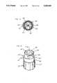
- FIG. 1is a perspective view of the medical coupling site of the present invention
- FIG. 2is a cross-sectional view of the coupling site taken along line 2--2 in FIG. 1, and additionally showing a male luer lock fitting for connection to the coupling site;
- FIG. 3is a view similar to FIG. 2 in which the male luer lock fitting is shown inserted into the coupling site prior to threaded engagement of the male luer lock fitting with the coupling site;
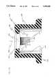
- FIG. 4is a cross-sectional view of the coupling site taken along line 4--4 in FIG. 1;
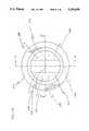
- FIG. 5is a cross-sectional view taken along line 5--5 in FIG. 2;
- FIG. 6is a perspective view of a second embodiment of the medical coupling device of the present invention.
- FIG. 7is a cross-sectional view taken along line 7--7 in FIG. 6, and additionally showing a male luer lock fitting for connection to the coupling site;
- FIG. 8is a cross-sectional view similar to FIG. 7 in which the male luer lock fitting is shown inserted into the coupling site prior to threaded engagement of the male luer lock with the coupling site;
- FIG. 9is a cross-sectional view similar to that shown in FIG. 2 illustrating an alternative configuration for the valve element
- FIG. 10is a cross-sectional view taken along line 10--10 in FIG. 9;
- FIG. 11is a cross-sectional view taken along line 11--11 in FIG. 9;
- FIG. 12is a cross-sectional view similar to that shown in FIG. 2 illustrating a further embodiment of the present invention.
- FIG. 13is a cross-sectional view of an alternative embodiment for the valve element of the present invention taken along line 13--13 in FIG. 15;
- FIG. 14is a cross-sectional view of the valve element of FIG. 13 taken along line 14--14 in FIG. 15;
- FIG. 15is a top plan view of the valve element of FIG. 13.
- FIG. 16is a bottom plan view of the valve element of FIG. 13.
- the coupling site 10generally includes a support base 12, a retainer 14 supported on the support base and a valve element 16 located within the retainer.
- the support base 12is formed from a plastic material
- the retainer 14is formed from a metal material such as coated aluminum
- the valve element 16is formed of an elastomeric material such as an elastomer which conforms to standard medical specifications.
- other materialsmay be used for forming the particular elements of the present medical coupling site 10 to the extent that the alternative materials permit the coupling site 10 to function with the advantages to be described below.
- the support base 12preferably includes a tubular luer taper portion 18 defining a longitudinal axis 20 of the coupling site 10.
- the luer taper portion 18is surrounded by a threaded locking collar 22 such that the coupling site 10 may be attached to a standard female luer fitting.
- an outwardly extending flange portion 24is attached to an inner end of the luer taper portion 18 extending from an end wall 26 of the collar 22.
- the valve member 16includes a tubular body portion 28 extending substantially parallel to the longitudinal axis 20 and defining a first end 30 and a second end 32 wherein the second end 32 is in contact with the support base 12 adjacent to the end wall 26.
- the valve element 16further includes a thin flexible diaphragm 34 extending across the first end 30 of the body portion 16.
- the diaphragm 34includes means defining a slit 36 extending diametrically across the diaphragm 34.
- the diaphragm 34defines opposing first and second sides 38, 40 wherein the first side 38 is formed as a concave surface and the second side 40 is formed as a convex surface.
- the concave first surface 38includes a peripheral edge lying in a plane defined by an annular end surface 42 of the body portion 16.
- the first surface 38is provided with a relatively shallow curvature such that the first surface 38 is easily cleaned by wiping of the surface. Also, as a result of forming the diaphragm 34 curved inwardly toward the port base 12, fluid pressure within the site 10 will exert an outwardly directed force on the diaphragm 34 and will tend to cause the material surrounding the slit 36 to compress inwardly, thus biasing the slit closed.
- the second surface 40is shown having a substantially cylindrical curvature, it should be noted that this surface may also be formed having a spherical or dome-shaped curvature.
- the valve element 16is further provided with biasing means which are preferably in the form of first and second ribs 44, 46 extending radially inwardly from an inner wall 48 of the body portion 16 toward the slit 36 in a direction from the second end 32 toward the first end 30.
- the rib members 44, 46are oriented such that they intersect and extend parallel to a plane which intersects the longitudinal axis 20 and extends perpendicular to the slit 36.
- each of the rib members 44, 46define a width dimension in a direction parallel to the slit 36 which is less than an interior diameter defined by the inner wall 48 of the valve body 16.
- the rib members 44, 46have a dimension in a direction parallel to the longitudinal axis 20 which decreases in a direction from the inner wall 48 toward the slit 36.
- the rib members 44, 46reinforce the diaphragm 34 and act to bias the slit 36 to a closed position. Further, by providing rib members 44, 46 which have a width dimension less than the inner diameter of the body portion 16, the space surrounding the rib members 44, 46 is available to accommodate elastomeric material of the diaphragm 34 and body portion 28 as the valve element 16 is distorted during insertion of a male luer taper 50 (see FIG. 2).
- the retainer 14is formed as a tubular sleeve defined by an elongated body 52 having a first end 54 adjacent to the first end 30 of the valve element 16 and a second end 56 adjacent to the second end 32 of the valve element 16.
- the first end 54 of the retainer 14is turned inwardly into the first end of the valve element 16 and is preferably folded over to form a double thickness portion. This portion forms a reduced area for slightly compressing the valve element 16 in the area around the diaphragm 34 to thereby form a seal preventing fluids from passing between the valve element 16 and the retainer 14.
- the second end 56is preferably crimped inwardly toward a gap formed between the flange portion 24 and the end wall 26 to thereby hold the second end 32 of the valve element 16 under the flange portion 24 such that the valve element 16 is firmly held in place on the support base 12.
- the valve body portion 28extends substantially along the length of the retainer 14 and isolates the retainer 14 from fluids flowing through the coupling site, as well as forms a direct fluid path through the site 10 to avoid the formation of crevices or pockets which may retain fluids and hinder flushing of the site between administration of different medicines.
- the inner surface of the elongated body 52preferably defines a diameter which is slightly smaller than the outer diameter of the body portion 28 prior to mounting in the coupling site 10.
- the retainer 14firmly engages the valve element 16 and applies a predetermined compression force for further biasing the material surrounding the slit 36 inwardly toward the axis 20 for closing the slit 36.
- the retainer 14further includes a pair of lugs 58, 60 extending radially outwardly from the outer surface of the retainer body 52.
- the retainer 14is preferably formed from thin material such as coated aluminum, which may be conveniently stamped to a desired shape.
- the lugs 58, 60may be formed as stamped protrusions in the body 52.
- the lugs 58, 60are configured to engage the double helix threads formed on the interior of a threaded locking collar 62 (see FIG. 2) for a standard male luer lock.
- the lugs 58, 60may be formed extending at a slight angle relative to a plane extending perpendicular to the longitudinal axis 20.
- the lugsmay be formed having an alternative configuration, such as a configuration defining threads extending around the entire circumference of the retainer body 52 and that other means of forming the thin metal retainer, such as machining, may be applied.
- the lugs 58, 60are preferably located adjacent to the first end 54 of the retainer 14 and the thickness of the retainer body portion 52 in at least the area adjacent to the lugs has a thickness, as measured in a direction perpendicular to the longitudinal axis 20, which is less than the thickness of the valve element body portion 28.
- the relationship between the thickness of the retainer 14 and the valve element 16is important since only a limited amount of space is available between a standard male luer taper 50 and the surrounded locking collar 62.
- a standard male luer lock 64is illustrated and may be in the form of a standard syringe end including a male luer taper 50 and a threaded locking collar 62.
- the male luer taper 50has an outer diameter of approximately 3.9 mm to 4.0 mm and the threaded locking collar 62 has a minimum inner diameter, as defined by the threaded portion of approximately 7.0 mm to 7.2 mm.
- the male luer taperis formed tapering inwardly at an angle of 6°.
- the retainer 14 of the coupling site 10is formed having a maximum outer diameter for the retainer body 52 of approximately 7.0 mm, and the inner wall 48 of the valve element 16 defines a minimum diameter of 4 mm.
- the configuration of the present coupling site 10results in a site which is particularly adapted to be received between the male luer tip 50 and the locking collar 62 with the outer surface of the site 10 forming a positive mechanical connection with the threads of the collar 62 and with the interior of the valve body 28 providing sufficient clearance for the male luer taper 50 to easily slide into the coupling site 10.
- end surface 65 of the luer taper 18may serve as a convenient stop surface for engaging the end of the luer taper 50 to define a positive lock position between the male luer lock 64 and the coupling site 10.
- the male luer taper 50causes the diaphragm 34 to be stretched and pushed into a distorted position adjacent to the inner wall 48, with an accompanying distortion of the ribs 44, 46.
- the coupling site 10 of the present inventionincorporates a flexible diaphragm member 34 having a slit 36 wherein the slit is biased to a closed position through forces exerted on the diaphragm member by a supporting tubular body portion 28 forming a passage for receiving the male luer taper.
- a diaphragm member 34 for forming the seal on the site endresults in a highly resilient opening offering reduced resistance to forces pushing the male luer taper 50 or other cannula into the coupling site 10 while also providing a reliable closure element when the male luer taper 50 is removed from the site 10.
- the present coupling site 10may also easily be used with a needle in that a needle may be inserted through the diaphragm 34 in the region surrounding the slit 36 if it should be necessary to infuse or withdraw fluids through a needle at the injection site.
- FIGS. 6-8a second embodiment of the present invention is shown and is designated generally as 10'.
- elements in the second embodiment corresponding to elements in the first embodimentare labeled with the same reference numeral primed.
- the embodiment of FIGS. 6-8differs from the previous embodiment in that the area surrounded by the flange portion 24' includes an enlarged passage defining a luer slip 66' which is adapted to receive the end of a standard male luer taper 50'.
- the area of the second end 32' of the body portion 16' and the second end 56' of the retainer 14'are formed with an enlarged diameter, as compared to the previous embodiment, in order to accommodate the enlarged luer slip area 66'.
- the portion of the valve body 28' and the retainer body 52' adjacent to the lugs 58', 60'is formed with the same diameter as in the previous embodiment such that the coupling site 10' will cooperate with a standard male luer lock 64' in the same manner as in the previous embodiment.
- the tip of the luer taper 50'will pass into the luer slip 66' whereby an additional seal is formed between the exterior of the luer taper 50' and the interior of the luer slip 66'.
- the contact between the luer taper 50' and luer slip 66'defines a positive lock position between the luer lock 64' and the coupling site 10'.
- FIGS. 6-8does not affect the advantages afforded by passage of the retainer 14' and valve element 16' in between the luer taper 50' and the locking collar 62' to form a sealed connection wherein the standard luer lock 64' is mechanically locked onto the coupling site 10'.
- FIGS. 9-11show an alternative to the first embodiment in which an alternative valve element 16" is shown and in which the elements for the retainer 14 and the support base 12 remain unchanged and are identified with the same reference numerals as in the first embodiment.
- the valve element 16" of the present embodimentdiffers from the valve element 16 of the first embodiment in that a different rib structure is provided for biasing the slit 36" to a closed position. Specifically, a pair of rib portions 44", 45" and 46", 47” are provided on opposing sides of the slit 36". Each pair of rib members 44", 45" and 46", 47" is separated by a space 68", 70", respectively.
- the rib members 44"-47"operate in the same manner as the ribs 44, 46 of the first embodiment to reinforce the diaphragm 34" and bias the slit 36" to a closed position.
- the spaces 68", 70"provide an area for the material of the valve element 16" to deform into when a male luer taper is inserted into the coupling site.
- the rib membersmay be provided in order to bias the valve diaphragm to a closed position.
- the curved surface of the ribs 44, 46 extending from the inner wall 48 of the valve element 16 to the slit 36may be formed as a straight inwardly angled surface or may be provided with some other shape.
- the design of the diaphragm 34 and the reinforcing rib members 44, 46 for biasing the slit to a closed positionmay be altered to provide a predetermined resistance to back flow through the valve element 16.
- the valve element 16may be designed to release fluid from the slit 36 at a predetermined pressure in order to avoid excessive pressure from being applied into a patient at an infusion site.
- the diaphragm 34may be formed as a planar element having opposing first and second sides which are substantially flat. By providing an outwardly facing planar surface, the valve of the present invention would be particularly easy to clean by wiping of the surface.
- FIG. 12shows a further alternative embodiment to the first embodiment in which elements of the further embodiment corresponding to elements in the first embodiment are labeled with the same reference numerals increased by 100.
- the retainer 114is a formed thin element of any relatively rigid material such as metal or plastic.
- the second end 156 of the retainerincludes an enlarged end surface 155 engaging a flange portion 157 of the valve element 116.
- the flange portion 157is located with a groove defined between an inner end of the luer taper portion 118 and a lip 159 extending from the support base 112.
- the lip 159firmly engages the enlarged second end 156 of the retainer 114 in frictional contact to positively maintain the elements of the coupling site 110 in position relative to each other.
- the coupling site 110operates in a manner identical to that of the previous embodiments and differs only in the manner of forming the retainer 114 and in the structure for mounting the retainer 114 and the valve element 116 to the support base 112.
- the retainer of the present inventionmay also be formed from a plastic material provided the plastic has sufficient rigidity to resist deformation during assembly and use of the coupling site.
- FIGS. 13-16illustrate a further embodiment of the invention in which elements corresponding to elements in the first embodiment are labeled with the same reference numerals increased by 200.
- the present embodimentis directed to an improved valve element 216 having stiffening ribs 270, 272 extending radially inwardly from opposing sides of the inner wall 248 to locations adjacent to respective ends of the slit 236.
- the stiffening ribs 270, 272are formed integrally with the elastomeric material of the diaphragm 234, and extend axially from the second or inner surface 240 of the diaphragm 234 toward the second end 232 of the valve element 216.
- the inner face 240 of the diaphragm 234 of the present embodimentis formed having a convex dome shape which is substantially the same shape as the first or outer concave surface 238.
- the valve element 216is provided with radially inwardly extending biasing ribs 244 and 246 for biasing the slit 236 closed.
- the biasing ribs 244, 246lie within and extend parallel to a first plane 274 which contains the longitudinal axis 220 and which is perpendicular to the slit 236, and the stiffening ribs 270, 272 extend parallel to a second plane 276 which is perpendicular to the first plane 274 and which also contains the longitudinal axis 220.
- the stiffening ribs 270, 272have a width dimension in a direction perpendicular to the slit 236 which is less than the interior diameter of the body portion 228.
- the stiffening ribs 270, 272act to prevent the diaphragm 234 from tearing adjacent to the ends of the slit 236, such that the slit 236 is prevented from propagating to the inner wall 248. In addition, the stiffening ribs 270, 272 ensure that the adjoining surfaces of the diaphragm 234 defining the slit 236 will be maintained in alignment with each other when they move together to close the slit 236.
- stiffening ribs 270, 272act to stiffen the diaphragm 234 adjacent to the ends of the slit 236, and are formed of the same elastomeric material as the diaphragm 234 and the body portion 228 such that they are adapted to be resiliently displaced when a male luer is inserted through the slit 236 to facilitate easy insertion of the luer.
- valve element 216 of the present embodimentis adapted to be positioned within a retainer having lugs for threadably engaging an internally threaded collar of a male luer lock such that the luer taper may be held in a positive locked position relative to the valve element 216.
- the medical coupling site of the present inventionovercomes the disadvantages associated with prior art sites.
- the present medical coupling siteis provided with a wall structure having a sufficiently thin dimension to pass within the space defined between a standard male luer taper and a locking collar for a standard male luer lock fitting.
- the outer surface of the coupling siteis provided with rigidly supported lugs for engaging the double helix threads of the threaded locking collar for a male luer lock whereby the coupling site is held in fixed mechanical engagement with the male luer lock.
- the present inventionalso has an advantage over prior art sites requiring a reduced diameter cannula for insertion through a valve element in that the present invention permits a standard luer taper to be inserted through the valve into the coupling site and the interior diameter of the coupling site is at least as large as the interior diameter of a standard luer taper.
- the coupling site of the present inventiondoes not impose any restrictions to flow resulting from reductions of diameter within the site.
- a further advantage of the present inventionresults from providing biasing means in the form of ribs for controlling the location of the diaphragm and thereby maintaining the slit in a closed position.
- the diaphragm of the present inventiondoes not require excessive forces directed inwardly toward the slit in order to maintain the slit in a closed position, and as a result thereof the ease of insertion of a luer taper into the valve is greatly enhanced.
- a thin rigid retainerin combination with a tubular valve element having a diaphragm extending across an end thereof provides a critical dual function of both providing a mounting structure for the radially extending lugs and also acting as a reinforcing structure to rigidly support the valve element and thereby ensure closure of the slit, as well as prevent inadvertent opening of the slit resulting from side forces applied to the coupling site at the location of the valve element.
- the medical coupling sitemay be incorporated into existing medical fluid systems without change over of equipment or the use of adapters to incorporate non-standard fittings.
- the present inventionis particularly adapted to be used with standard male luer locks, it may also be used with other cannula or may be accessed with a conventional steel needle.
- the coupling sitefurther provides for a positive feedback of a locked connection such that medical personnel will be able to quickly connect male luer lock fittings to the site.
- valve element diaphragmenables the present coupling site to be used for multiple insertions and with extended indwell times while maintaining its capability to form a fluid-tight seal at the slit upon removal of a luer taper or cannula.
- the design of the coupling site with the valve element extending from a point adjacent to the first end of the sleeve to a point in contact with the support basefurther ensures that crevices for containing pockets of fluid are avoided such that flushing of the valve in between administration of medicines is facilitated.
Landscapes
- Engineering & Computer Science (AREA)
- Health & Medical Sciences (AREA)
- Heart & Thoracic Surgery (AREA)
- General Engineering & Computer Science (AREA)
- Anesthesiology (AREA)
- Pulmonology (AREA)
- Mechanical Engineering (AREA)
- Biomedical Technology (AREA)
- Hematology (AREA)
- Life Sciences & Earth Sciences (AREA)
- Animal Behavior & Ethology (AREA)
- General Health & Medical Sciences (AREA)
- Public Health (AREA)
- Veterinary Medicine (AREA)
- Infusion, Injection, And Reservoir Apparatuses (AREA)
Abstract
Description
Claims (18)
Priority Applications (3)
| Application Number | Priority Date | Filing Date | Title |
|---|---|---|---|
| US08/068,777US5295658A (en) | 1987-04-27 | 1993-06-01 | Medical coupling site including slit reinforcing members |
| PCT/US1994/003234WO1994022523A1 (en) | 1993-04-05 | 1994-03-24 | Medical coupling site including slit reinforcing members |
| AU64161/94AAU6416194A (en) | 1993-04-05 | 1994-03-24 | Medical coupling site including slit reinforcing members |
Applications Claiming Priority (3)
| Application Number | Priority Date | Filing Date | Title |
|---|---|---|---|
| US07/042,525US4724244A (en) | 1984-06-16 | 1987-04-27 | Coating agents and their preparation, and cathodic electrocoating |
| US07893813US5251873B1 (en) | 1992-06-04 | 1992-06-04 | Medical coupling site. |
| US08/068,777US5295658A (en) | 1987-04-27 | 1993-06-01 | Medical coupling site including slit reinforcing members |
Related Parent Applications (1)
| Application Number | Title | Priority Date | Filing Date |
|---|---|---|---|
| US07/042,525ContinuationUS4724244A (en) | 1984-06-16 | 1987-04-27 | Coating agents and their preparation, and cathodic electrocoating |
Publications (1)
| Publication Number | Publication Date |
|---|---|
| US5295658Atrue US5295658A (en) | 1994-03-22 |
Family
ID=26719333
Family Applications (1)
| Application Number | Title | Priority Date | Filing Date |
|---|---|---|---|
| US08/068,777Expired - Fee RelatedUS5295658A (en) | 1987-04-27 | 1993-06-01 | Medical coupling site including slit reinforcing members |
Country Status (1)
| Country | Link |
|---|---|
| US (1) | US5295658A (en) |
Cited By (145)
| Publication number | Priority date | Publication date | Assignee | Title |
|---|---|---|---|---|
| US5354275A (en)* | 1993-09-13 | 1994-10-11 | Minnesota Mining And Manufacturing Company | Injection or sampling site |
| US5403293A (en)* | 1994-01-03 | 1995-04-04 | Abbott Laboratories | Molded partial pre-slit reseal |
| US5409471A (en)* | 1993-07-06 | 1995-04-25 | Vernay Laboratories, Inc. | Method of lubricating a medical coupling site |
| US5584850A (en)* | 1995-05-25 | 1996-12-17 | Applied Medical Resources Corporation | Trocar having an anti-inversion seal |
| US5676346A (en)* | 1995-05-16 | 1997-10-14 | Ivac Holdings, Inc. | Needleless connector valve |
| US5685858A (en)* | 1995-05-17 | 1997-11-11 | Datascope Corp. | Slidable seal for use with a catheter gard unit |
| US5807348A (en)* | 1996-11-27 | 1998-09-15 | Elcam Plastics | Needleless valve |
| US5814024A (en)* | 1996-11-27 | 1998-09-29 | Elcam Plastics | Needleless valve |
| US5957898A (en) | 1997-05-20 | 1999-09-28 | Baxter International Inc. | Needleless connector |
| US6024729A (en)* | 1998-03-10 | 2000-02-15 | Vernay Laboratories, Inc. | Hemostasis valve assembly including guide wire seal |
| US6068011A (en)* | 1993-10-13 | 2000-05-30 | Paradis; Joseph R. | Control of fluid flow |
| WO2000033901A1 (en)* | 1998-12-07 | 2000-06-15 | Std Manufacturing, Inc. | Implantable vascular access device |
| US6142446A (en)* | 1995-05-16 | 2000-11-07 | Alaris Medical Systems, Inc. | Medical adapter having needleless valve and sharpened cannula |
| US6162206A (en) | 1997-12-23 | 2000-12-19 | Baxter International Inc. | Resealable access site |
| US6171287B1 (en) | 1998-05-29 | 2001-01-09 | Lawrence A. Lynn | Luer receiver and method for fluid transfer |
| US6206058B1 (en) | 1998-11-09 | 2001-03-27 | The Procter & Gamble Company | Integrated vent and fluid transfer fitment |
| US6228065B1 (en) | 1994-02-15 | 2001-05-08 | Lawrence A. Lynn | Displacement activated medical check valve |
| GB2356144A (en)* | 1999-11-10 | 2001-05-16 | Nmt Group Plc | Seal for syringe barrel |
| US6261282B1 (en) | 1997-05-20 | 2001-07-17 | Baxter International Inc. | Needleless connector |
| USRE37357E1 (en) | 1994-05-25 | 2001-09-04 | Lawrence A. Lynn | Luer-receiving medical valve and fluid transfer method |
| WO2002038460A1 (en)* | 2000-11-07 | 2002-05-16 | Biocrystal Ltd. | Access port septum and assembly |
| US6491668B1 (en)* | 1998-12-03 | 2002-12-10 | Joseph R. Paradis | Needleless fluid transfer |
| EP1281897A1 (en)* | 2001-07-30 | 2003-02-05 | Hewlett-Packard Company | Elastomeric valve |
| US20040006312A1 (en)* | 1999-11-10 | 2004-01-08 | Donnan Jeremy Francis | Hypodermic syringes |
| US20040068239A1 (en)* | 2002-10-04 | 2004-04-08 | Utterberg David S. | Injection site for male luer or other tubular connector |
| US20040073176A1 (en)* | 2002-10-04 | 2004-04-15 | Utterberg David S. | Medical device with elastomeric penetrable wall and inner seal |
| US20040102738A1 (en)* | 2002-11-26 | 2004-05-27 | Medical Ventures, L.L.C. | Pressure actuated flow control valve |
| US20040199126A1 (en)* | 2001-12-07 | 2004-10-07 | Harding Weston F | Needleless luer access connector |
| US6808161B1 (en)* | 1999-09-16 | 2004-10-26 | Terumo Kabushiki Kaisha | Connector |
| US20060058744A1 (en)* | 2000-04-26 | 2006-03-16 | Tallarida Steven J | Implantable hemodialysis access device |
| US7033339B1 (en) | 1998-05-29 | 2006-04-25 | Becton Dickinson And Company (Part Interest) | Self sealing luer receiving stopcock |
| US20060100592A1 (en)* | 2004-07-13 | 2006-05-11 | Kenneth Eliasen | Infusion port |
| US20060155245A1 (en)* | 2002-07-04 | 2006-07-13 | Kevin Woehr | Catheter insertion device |
| US20060224129A1 (en)* | 1998-12-07 | 2006-10-05 | Beasley Jim C | Septum including at least one identifiable feature, access ports including same, and related methods |
| USRE39334E1 (en) | 1994-05-25 | 2006-10-10 | Lynn Lawrence A | Luer-receiving medical valve and fluid transfer method |
| US20060264991A1 (en)* | 2005-04-29 | 2006-11-23 | Applied Medical Resources Corporation | Seal housing having anti-inversion features |
| US20070078416A1 (en)* | 2005-10-04 | 2007-04-05 | Kenneth Eliasen | Two-piece inline vascular access portal |
| US20070161940A1 (en)* | 2005-12-02 | 2007-07-12 | Blanchard Daniel B | Pressure activated proximal valves |
| US20070225648A1 (en)* | 2006-03-24 | 2007-09-27 | Chris Winsor | Intravenous injection site with split septum and pressure activated flow control valve |
| US20070233017A1 (en)* | 2006-10-18 | 2007-10-04 | Medical Components, Inc. | Venous access port assembly with radiopaque indicia |
| US20070287989A1 (en)* | 2006-05-08 | 2007-12-13 | Becton, Dickinson & Company | Vascular access device pathogenic status indication |
| US20070293822A1 (en)* | 2006-05-08 | 2007-12-20 | Becton, Dickinson & Company | Vascular access device time sensitive status indication |
| US20080027401A1 (en)* | 2006-07-28 | 2008-01-31 | Becton, Dickinson And Company | Vascular access device filtration |
| US20080027400A1 (en)* | 2006-07-28 | 2008-01-31 | Becton, Dickinson And Company | Vascular access device non-adhering surfaces |
| US20080027398A1 (en)* | 2006-07-28 | 2008-01-31 | Becton, Dickinson And Company | Vascular access device volume displacement |
| US20080027399A1 (en)* | 2006-07-28 | 2008-01-31 | Becton, Dickinson And Company | Antimicrobial vascular access device |
| US20080027410A1 (en)* | 2006-07-28 | 2008-01-31 | Becton, Dickinson And Company | Vascular access device non-adhering membranes |
| US20080033363A1 (en)* | 2004-01-23 | 2008-02-07 | Haberland Gary W | Trocar and cannula assembly having conical valve and related methods |
| US20080065021A1 (en)* | 2006-09-07 | 2008-03-13 | Gyrus Medical Limited | Surgical instrument |
| US20080086099A1 (en)* | 2006-10-05 | 2008-04-10 | Becton, Dickinson And Company | Vascular access device including a tear-resistant septum |
| US20080086100A1 (en)* | 2006-10-05 | 2008-04-10 | Becton, Dickinson And Company | Vascular access device stagnant fluid displacement |
| US20080086097A1 (en)* | 2006-10-05 | 2008-04-10 | Becton, Dickinson And Company | Vascular access device fluid flow direction |
| US20080093571A1 (en)* | 2006-10-23 | 2008-04-24 | Baxter International Inc. | Luer activated device with minimal fluid displacement |
| US20080097407A1 (en)* | 2006-10-18 | 2008-04-24 | Michael Plishka | Luer activated device with compressible valve element |
| US20080108939A1 (en)* | 2006-11-06 | 2008-05-08 | Becton, Dickinson And Company | Vascular access devices including a tear-resistant septum |
| US20080108973A1 (en)* | 2006-11-02 | 2008-05-08 | Becton, Dickinson And Company | Vascular access device gas displacement |
| US20080132877A1 (en)* | 2006-11-02 | 2008-06-05 | Becton, Dickinson And Company | Vascular access device chamber venting |
| US20080132833A1 (en)* | 2006-11-06 | 2008-06-05 | Becton, Dickinson And Company | Vascular access devices including a tear-resistant septum |
| US20080132832A1 (en)* | 2006-10-11 | 2008-06-05 | Becton, Dickinson And Company | Vascular access device including a tear-resistant septum |
| US20080140025A1 (en)* | 2005-03-04 | 2008-06-12 | C. R. Bard, Inc. | Access port identification systems and methods |
| US20080161763A1 (en)* | 2006-07-28 | 2008-07-03 | Becton, Dickinson And Company | Vascular access device antimicrobial materials and solutions |
| US20080172005A1 (en)* | 2006-10-18 | 2008-07-17 | Jepson Steven C | Luer activated device with valve element under tension |
| US20080172003A1 (en)* | 2006-10-18 | 2008-07-17 | Michael Plishka | Luer activated device |
| US20080172004A1 (en)* | 2006-10-18 | 2008-07-17 | Michael Plishka | Luer activated device with stretchable valve element |
| US20080200903A1 (en)* | 2006-11-06 | 2008-08-21 | Becton, Dickinson And Company | Vascular access device housing venting |
| US20080200904A1 (en)* | 2006-11-06 | 2008-08-21 | Becton, Dickinson And Company | Vascular access device septum venting |
| US20080215004A1 (en)* | 2006-11-02 | 2008-09-04 | Becton, Dickinson And Company | Vascular access device chamber replacement |
| US20080287906A1 (en)* | 2006-11-06 | 2008-11-20 | Becton, Dickinson And Company | Extravascular system venting |
| US20080294113A1 (en)* | 2007-05-22 | 2008-11-27 | Oivind Brockmeier | Access Assembly With Ribbed Seal |
| US20080319399A1 (en)* | 2007-06-20 | 2008-12-25 | Medical Components, Inc. | Venous access port with molded and/or radiopaque indicia |
| US7469458B1 (en) | 2004-08-11 | 2008-12-30 | Proteckt Catheters, Llc | Method of assembling a catheter with integrated pre-slit cannula diaphragm |
| US20090024024A1 (en)* | 2007-07-19 | 2009-01-22 | Innovative Medical Devices, Llc | Venous Access Port Assembly with X-Ray Discernable Indicia |
| US20090088729A1 (en)* | 2006-10-05 | 2009-04-02 | Becton, Dickinson And Company | Vascular Access Devices Including A Tear-Resistant Septum |
| US7635357B2 (en) | 1994-06-20 | 2009-12-22 | Mayer Bruno Franz P | Needleless injection site |
| US20100030164A1 (en)* | 2008-08-04 | 2010-02-04 | Np Medical Inc. | Medical Valve with Raised Seal |
| US7666166B1 (en) | 2004-12-27 | 2010-02-23 | Blivic, Llc | Bloodless intravenous integrated catheter |
| US20100069743A1 (en)* | 2005-03-04 | 2010-03-18 | C. R. Bard, Inc. | Systems and methods for identifying an access port |
| US20100094892A1 (en)* | 2008-10-09 | 2010-04-15 | International Business Machines Corporation | Automated propagation of non-conflicting queries in distributed databases |
| US20100272148A1 (en)* | 2009-04-23 | 2010-10-28 | Medtronic, Inc. | Multiple Use Temperature Monitor Adapter, System and Method of Using Same |
| US20100298782A1 (en)* | 2009-05-19 | 2010-11-25 | Nexus Medical, Llc | Intravascular valve component with improved valve positioning |
| US20110009717A1 (en)* | 2009-07-09 | 2011-01-13 | Becton, Dickinson And Company | Blood sampling device |
| US7947022B2 (en) | 2005-03-04 | 2011-05-24 | C. R. Bard, Inc. | Access port identification systems and methods |
| USD644731S1 (en) | 2010-03-23 | 2011-09-06 | Icu Medical, Inc. | Medical connector |
| US8021324B2 (en) | 2007-07-19 | 2011-09-20 | Medical Components, Inc. | Venous access port assembly with X-ray discernable indicia |
| US8025639B2 (en) | 2005-04-27 | 2011-09-27 | C. R. Bard, Inc. | Methods of power injecting a fluid through an access port |
| US8029482B2 (en) | 2005-03-04 | 2011-10-04 | C. R. Bard, Inc. | Systems and methods for radiographically identifying an access port |
| US8105314B2 (en) | 2006-10-25 | 2012-01-31 | Icu Medical, Inc. | Medical connector |
| US8177772B2 (en) | 2005-09-26 | 2012-05-15 | C. R. Bard, Inc. | Catheter connection systems |
| US20120149987A1 (en)* | 2007-10-05 | 2012-06-14 | Tyco Healthcare Group Lp | Seal anchor for use in surgical procedures |
| US8337475B2 (en) | 2004-10-12 | 2012-12-25 | C. R. Bard, Inc. | Corporeal drainage system |
| USD676955S1 (en) | 2010-12-30 | 2013-02-26 | C. R. Bard, Inc. | Implantable access port |
| WO2013033726A1 (en)* | 2011-09-02 | 2013-03-07 | Quinonez Carlo Joseph | Universal hardware platform and toolset for operating and fabricating microfluidic devices |
| USD682416S1 (en) | 2010-12-30 | 2013-05-14 | C. R. Bard, Inc. | Implantable access port |
| US8444628B2 (en) | 2000-07-11 | 2013-05-21 | Icu Medical, Inc. | Needleless medical connector |
| US8454579B2 (en) | 2009-03-25 | 2013-06-04 | Icu Medical, Inc. | Medical connector with automatic valves and volume regulator |
| US8454563B2 (en) | 2009-10-09 | 2013-06-04 | Rogelio A. Insignares | Trocar and cannula assembly having improved conical valve, and methods related thereto |
| US20130165868A1 (en)* | 2011-10-06 | 2013-06-27 | Becton, Dickinson And Company | Multiple use stretching and non-penetrating blood control valves |
| US8486024B2 (en) | 2011-04-27 | 2013-07-16 | Covidien Lp | Safety IV catheter assemblies |
| US20130299021A1 (en)* | 2011-01-28 | 2013-11-14 | Ditta Paolo Giuseppe Gobbi Frattini | Hermetic connector, pierceable without needle and automatically and sealingly reclosable, for devices intended for collecting and dispensing liquid solutions for pharmaceutical and/or nutritional use |
| US8628497B2 (en) | 2011-09-26 | 2014-01-14 | Covidien Lp | Safety catheter |
| US8636721B2 (en) | 2003-11-20 | 2014-01-28 | Henry M. Jackson Foundation For The Advancement Of Military Medicine, Inc. | Portable hand pump for evacuation of fluids |
| US8641676B2 (en) | 2005-04-27 | 2014-02-04 | C. R. Bard, Inc. | Infusion apparatuses and methods of use |
| AU2011239219B2 (en)* | 2005-03-31 | 2014-03-20 | Covidien Lp | Surgical hand access apparatus |
| US8715244B2 (en) | 2009-07-07 | 2014-05-06 | C. R. Bard, Inc. | Extensible internal bolster for a medical device |
| US8715250B2 (en) | 2011-09-26 | 2014-05-06 | Covidien Lp | Safety catheter and needle assembly |
| US8758306B2 (en) | 2010-05-17 | 2014-06-24 | Icu Medical, Inc. | Medical connectors and methods of use |
| US8834422B2 (en) | 2011-10-14 | 2014-09-16 | Covidien Lp | Vascular access assembly and safety device |
| US8882714B1 (en) | 2009-01-23 | 2014-11-11 | Robert J. Perry | Needle with gated stylet |
| US8932271B2 (en) | 2008-11-13 | 2015-01-13 | C. R. Bard, Inc. | Implantable medical devices including septum-based indicators |
| US8939938B2 (en) | 2006-10-12 | 2015-01-27 | Covidien Lp | Needle tip protector |
| US9028425B2 (en) | 2010-07-15 | 2015-05-12 | Becton, Dickinson And Company | Vented blood sampling device |
| US9079004B2 (en) | 2009-11-17 | 2015-07-14 | C. R. Bard, Inc. | Overmolded access port including anchoring and identification features |
| US9186494B2 (en) | 2004-11-05 | 2015-11-17 | Icu Medical, Inc. | Medical connector |
| US9265912B2 (en) | 2006-11-08 | 2016-02-23 | C. R. Bard, Inc. | Indicia informative of characteristics of insertable medical devices |
| US20160121054A1 (en)* | 2013-03-28 | 2016-05-05 | Bayer Medical Care Inc. | Sterility enhanced closure for a fluid path |
| US9474888B2 (en) | 2005-03-04 | 2016-10-25 | C. R. Bard, Inc. | Implantable access port including a sandwiched radiopaque insert |
| US9480831B2 (en) | 2009-12-04 | 2016-11-01 | Versago Vascular Access, Inc. | Vascular access port |
| US9579496B2 (en) | 2007-11-07 | 2017-02-28 | C. R. Bard, Inc. | Radiopaque and septum-based indicators for a multi-lumen implantable port |
| US9592374B2 (en) | 2010-09-01 | 2017-03-14 | Becton, Dickinson And Company | Catheter adapter having UV-C antimicrobial radiation source and access window within catheter lumen for intravenous therapy |
| USD786427S1 (en) | 2014-12-03 | 2017-05-09 | Icu Medical, Inc. | Fluid manifold |
| US9642986B2 (en) | 2006-11-08 | 2017-05-09 | C. R. Bard, Inc. | Resource information key for an insertable medical device |
| US20170197073A1 (en)* | 2015-10-17 | 2017-07-13 | Halkey-Roberts Corporation | Swabable valve with curvilinear valve stem |
| USD793551S1 (en) | 2014-12-03 | 2017-08-01 | Icu Medical, Inc. | Fluid manifold |
| US9764124B2 (en) | 2014-03-31 | 2017-09-19 | Versago Vascular Access, Inc. | Vascular access port |
| US9788773B2 (en) | 2008-05-21 | 2017-10-17 | Robert J. Perry | Vein presentation enhancement device |
| US20190060616A1 (en)* | 2017-08-31 | 2019-02-28 | I-V Access Technology, Inc. | Methods and devices for vascular access |
| US10238851B2 (en) | 2015-07-14 | 2019-03-26 | Versago Vascular Access, Inc. | Medical access ports, transfer devices and methods of use thereof |
| US10307581B2 (en) | 2005-04-27 | 2019-06-04 | C. R. Bard, Inc. | Reinforced septum for an implantable medical device |
| US10369349B2 (en) | 2013-12-11 | 2019-08-06 | Icu Medical, Inc. | Medical fluid manifold |
| US10369345B2 (en) | 2014-03-31 | 2019-08-06 | Versago Vascular Access, Inc. | Medical access port, systems and methods of use thereof |
| US10512734B2 (en) | 2014-04-03 | 2019-12-24 | Versago Vascular Access, Inc. | Devices and methods for installation and removal of a needle tip of a needle |
| US10828465B2 (en) | 2008-01-14 | 2020-11-10 | I-V Access Technology, Inc. | Apparatus for peripheral vascular access |
| US10905866B2 (en) | 2014-12-18 | 2021-02-02 | Versago Vascular Access, Inc. | Devices, systems and methods for removal and replacement of a catheter for an implanted access port |
| US11058815B2 (en) | 2017-12-21 | 2021-07-13 | Versago Vascular Access, Inc. | Medical access ports, transfer devices and methods of use thereof |
| US11154687B2 (en) | 2014-12-18 | 2021-10-26 | Versago Vascular Access, Inc. | Catheter patency systems and methods |
| US11235136B2 (en) | 2016-10-17 | 2022-02-01 | Halkey-Roberts Corporation | Swabable valve with curvilinear valve stem |
| US11318286B2 (en) | 2020-03-23 | 2022-05-03 | I-V Access Technology, Inc. | Catheter needle assembly with enclosable needle |
| US11324939B2 (en) | 2017-08-31 | 2022-05-10 | I-V Access Technology, Inc. | Methods and devices for vascular access |
| US11344318B2 (en) | 2016-07-18 | 2022-05-31 | Merit Medical Systems, Inc. | Inflatable radial artery compression device |
| US11529170B2 (en) | 2020-04-29 | 2022-12-20 | Covidien Lp | Expandable surgical access port |
| US11607525B1 (en)* | 2022-06-30 | 2023-03-21 | I-V Access Technology, Inc. | Methods and devices for vascular access |
| US20240001079A1 (en)* | 2022-06-30 | 2024-01-04 | I-V Access Technology, Inc. | Methods and devices for vascular access |
| US11890443B2 (en) | 2008-11-13 | 2024-02-06 | C. R. Bard, Inc. | Implantable medical devices including septum-based indicators |
| US12426864B2 (en) | 2021-06-18 | 2025-09-30 | Merit Medical Systems, Inc. | Hemostasis devices and methods of use |
| US12440661B2 (en) | 2022-05-18 | 2025-10-14 | Icu Medical, Inc. | Medical fluid transfer device |
Citations (20)
| Publication number | Priority date | Publication date | Assignee | Title |
|---|---|---|---|---|
| US3837381A (en)* | 1972-12-26 | 1974-09-24 | Prod Adex Sa | Shuttoff valve device |
| US4143853A (en)* | 1977-07-14 | 1979-03-13 | Metatech Corporation | Valve for use with a catheter or the like |
| US4436519A (en)* | 1981-05-28 | 1984-03-13 | Argon Medical Corp. | Removable hemostasis valve |
| US4568336A (en)* | 1984-04-26 | 1986-02-04 | Microbiological Applications, Inc. | Pre-filled hypodermic syringes |
| US4607671A (en)* | 1984-08-21 | 1986-08-26 | Baxter Travenol Laboratories, Inc. | Reconstitution device |
| US4610674A (en)* | 1984-09-13 | 1986-09-09 | Terumo Kabushi Kaisha | Catheter introducing instrument |
| US4629450A (en)* | 1984-05-09 | 1986-12-16 | Terumo Corporation | Catheter introducing instrument |
| US4673394A (en)* | 1986-01-17 | 1987-06-16 | Strato Medical Corporation | Implantable treatment reservoir |
| US4673400A (en)* | 1986-02-10 | 1987-06-16 | Martin Ivan W | Aseptic connector assembly for conduits for sterile fluids |
| WO1988001881A1 (en)* | 1986-09-18 | 1988-03-24 | Aktiebolaget Leo | Connector and a disposable assembly utilizing said connector |
| US4759756A (en)* | 1984-09-14 | 1988-07-26 | Baxter Travenol Laboratories, Inc. | Reconstitution device |
| US4765588A (en)* | 1986-08-18 | 1988-08-23 | Vernay Laboratories, Inc. | Check valve for use with a syringe |
| US4786281A (en)* | 1985-08-02 | 1988-11-22 | Farmitalia Carlo Erba S.P.A. | Device for connecting one end of a liquid medicament delivery cannula to an apparatus for connecting a syringe to a vial containing the medicament |
| US4850975A (en)* | 1987-03-27 | 1989-07-25 | Yuichi Furukawa | Catheter introducer for angiography |
| WO1990011103A2 (en)* | 1989-03-17 | 1990-10-04 | Baxter International Inc. | Pre-slit injection site and tapered cannula |
| US5092840A (en)* | 1990-07-16 | 1992-03-03 | Healy Patrick M | Valved medicine container |
| US5100394A (en)* | 1988-01-25 | 1992-03-31 | Baxter International Inc. | Pre-slit injection site |
| US5104379A (en)* | 1989-04-03 | 1992-04-14 | Olympus Optical Co., Ltd. | Medical instrument and valve to be mounted on a mount piece of that instrument |
| US5114408A (en)* | 1990-10-18 | 1992-05-19 | Daig Corporation | Universal hemostasis valve having improved sealing characteristics |
| US5171234A (en)* | 1988-01-25 | 1992-12-15 | Baxter International, Inc. | Method of effecting a transfer of fluid from a source to a receiver |
- 1993
- 1993-06-01USUS08/068,777patent/US5295658A/ennot_activeExpired - Fee Related
Patent Citations (21)
| Publication number | Priority date | Publication date | Assignee | Title |
|---|---|---|---|---|
| US3837381A (en)* | 1972-12-26 | 1974-09-24 | Prod Adex Sa | Shuttoff valve device |
| US4143853A (en)* | 1977-07-14 | 1979-03-13 | Metatech Corporation | Valve for use with a catheter or the like |
| US4436519A (en)* | 1981-05-28 | 1984-03-13 | Argon Medical Corp. | Removable hemostasis valve |
| US4436519B1 (en)* | 1981-05-28 | 1989-04-04 | ||
| US4568336A (en)* | 1984-04-26 | 1986-02-04 | Microbiological Applications, Inc. | Pre-filled hypodermic syringes |
| US4629450A (en)* | 1984-05-09 | 1986-12-16 | Terumo Corporation | Catheter introducing instrument |
| US4607671A (en)* | 1984-08-21 | 1986-08-26 | Baxter Travenol Laboratories, Inc. | Reconstitution device |
| US4610674A (en)* | 1984-09-13 | 1986-09-09 | Terumo Kabushi Kaisha | Catheter introducing instrument |
| US4759756A (en)* | 1984-09-14 | 1988-07-26 | Baxter Travenol Laboratories, Inc. | Reconstitution device |
| US4786281A (en)* | 1985-08-02 | 1988-11-22 | Farmitalia Carlo Erba S.P.A. | Device for connecting one end of a liquid medicament delivery cannula to an apparatus for connecting a syringe to a vial containing the medicament |
| US4673394A (en)* | 1986-01-17 | 1987-06-16 | Strato Medical Corporation | Implantable treatment reservoir |
| US4673400A (en)* | 1986-02-10 | 1987-06-16 | Martin Ivan W | Aseptic connector assembly for conduits for sterile fluids |
| US4765588A (en)* | 1986-08-18 | 1988-08-23 | Vernay Laboratories, Inc. | Check valve for use with a syringe |
| WO1988001881A1 (en)* | 1986-09-18 | 1988-03-24 | Aktiebolaget Leo | Connector and a disposable assembly utilizing said connector |
| US4850975A (en)* | 1987-03-27 | 1989-07-25 | Yuichi Furukawa | Catheter introducer for angiography |
| US5100394A (en)* | 1988-01-25 | 1992-03-31 | Baxter International Inc. | Pre-slit injection site |
| US5171234A (en)* | 1988-01-25 | 1992-12-15 | Baxter International, Inc. | Method of effecting a transfer of fluid from a source to a receiver |
| WO1990011103A2 (en)* | 1989-03-17 | 1990-10-04 | Baxter International Inc. | Pre-slit injection site and tapered cannula |
| US5104379A (en)* | 1989-04-03 | 1992-04-14 | Olympus Optical Co., Ltd. | Medical instrument and valve to be mounted on a mount piece of that instrument |
| US5092840A (en)* | 1990-07-16 | 1992-03-03 | Healy Patrick M | Valved medicine container |
| US5114408A (en)* | 1990-10-18 | 1992-05-19 | Daig Corporation | Universal hemostasis valve having improved sealing characteristics |
Cited By (352)
| Publication number | Priority date | Publication date | Assignee | Title |
|---|---|---|---|---|
| US5409471A (en)* | 1993-07-06 | 1995-04-25 | Vernay Laboratories, Inc. | Method of lubricating a medical coupling site |
| US5354275A (en)* | 1993-09-13 | 1994-10-11 | Minnesota Mining And Manufacturing Company | Injection or sampling site |
| US6068011A (en)* | 1993-10-13 | 2000-05-30 | Paradis; Joseph R. | Control of fluid flow |
| US5403293A (en)* | 1994-01-03 | 1995-04-04 | Abbott Laboratories | Molded partial pre-slit reseal |
| US6228065B1 (en) | 1994-02-15 | 2001-05-08 | Lawrence A. Lynn | Displacement activated medical check valve |
| US7470261B2 (en) | 1994-04-22 | 2008-12-30 | Lynn Lawrence A | Medical valve |
| USRE39334E1 (en) | 1994-05-25 | 2006-10-10 | Lynn Lawrence A | Luer-receiving medical valve and fluid transfer method |
| USRE37357E1 (en) | 1994-05-25 | 2001-09-04 | Lawrence A. Lynn | Luer-receiving medical valve and fluid transfer method |
| US7635357B2 (en) | 1994-06-20 | 2009-12-22 | Mayer Bruno Franz P | Needleless injection site |
| US6142446A (en)* | 1995-05-16 | 2000-11-07 | Alaris Medical Systems, Inc. | Medical adapter having needleless valve and sharpened cannula |
| US5676346A (en)* | 1995-05-16 | 1997-10-14 | Ivac Holdings, Inc. | Needleless connector valve |
| US5685858A (en)* | 1995-05-17 | 1997-11-11 | Datascope Corp. | Slidable seal for use with a catheter gard unit |
| US5584850A (en)* | 1995-05-25 | 1996-12-17 | Applied Medical Resources Corporation | Trocar having an anti-inversion seal |
| US5814024A (en)* | 1996-11-27 | 1998-09-29 | Elcam Plastics | Needleless valve |
| US5807348A (en)* | 1996-11-27 | 1998-09-15 | Elcam Plastics | Needleless valve |
| US5957898A (en) | 1997-05-20 | 1999-09-28 | Baxter International Inc. | Needleless connector |
| USRE43142E1 (en) | 1997-05-20 | 2012-01-24 | Baxter International, Inc. | Needleless connector |
| US6669681B2 (en) | 1997-05-20 | 2003-12-30 | Baxter International Inc. | Needleless connector |
| US6261282B1 (en) | 1997-05-20 | 2001-07-17 | Baxter International Inc. | Needleless connector |
| US6344033B1 (en) | 1997-05-20 | 2002-02-05 | Baxter International, Inc. | Needleless connector |
| US6162206A (en) | 1997-12-23 | 2000-12-19 | Baxter International Inc. | Resealable access site |
| US6024729A (en)* | 1998-03-10 | 2000-02-15 | Vernay Laboratories, Inc. | Hemostasis valve assembly including guide wire seal |
| US7033339B1 (en) | 1998-05-29 | 2006-04-25 | Becton Dickinson And Company (Part Interest) | Self sealing luer receiving stopcock |
| US8475416B2 (en) | 1998-05-29 | 2013-07-02 | Lawrence A. Lynn | Luer receiver and method for fluid transfer |
| US6171287B1 (en) | 1998-05-29 | 2001-01-09 | Lawrence A. Lynn | Luer receiver and method for fluid transfer |
| US7998122B2 (en) | 1998-05-29 | 2011-08-16 | Becton, Dickinson & Company | Luer receiver and method for fluid transfer |
| US8403894B2 (en) | 1998-05-29 | 2013-03-26 | Becton, Dickinson and Company (partial interest) | Luer receiver and method for fluid transfer |
| US20080048144A1 (en)* | 1998-05-29 | 2008-02-28 | Lynn Lawrence A | Luer Receiver and Method for Fluid Transfer |
| US20080051733A1 (en)* | 1998-05-29 | 2008-02-28 | Lynn Lawrence A | Luer Receiver and Method for Fluid Transfer |
| US20080108956A1 (en)* | 1998-05-29 | 2008-05-08 | Lynn Lawrence A | Luer Receiver and Method for Fluid Transfer |
| US20060129112A1 (en)* | 1998-05-29 | 2006-06-15 | Lynn Lawrence A | Luer receiver and method for fluid transfer |
| US8808254B2 (en) | 1998-05-29 | 2014-08-19 | Becton Dickinson And Company | Luer receiver and method for fluid transfer |
| US6491069B2 (en) | 1998-11-09 | 2002-12-10 | The Procter & Gamble Company | Integrated vent and fluid transfer fitment |
| US6427730B2 (en) | 1998-11-09 | 2002-08-06 | The Procter & Gamble Company | Integrated vent and fluid transfer fitment |
| US20040007287A1 (en)* | 1998-11-09 | 2004-01-15 | The Procter & Gamble Company | Integrated vent and fluid transfer fitment |
| US6206058B1 (en) | 1998-11-09 | 2001-03-27 | The Procter & Gamble Company | Integrated vent and fluid transfer fitment |
| US6612344B2 (en) | 1998-11-09 | 2003-09-02 | The Procter & Gamble Company | Integrated vent and fluid transfer fitment |
| US6491668B1 (en)* | 1998-12-03 | 2002-12-10 | Joseph R. Paradis | Needleless fluid transfer |
| US20100280465A1 (en)* | 1998-12-07 | 2010-11-04 | Std Med, Inc | Implantable Vascular Access Device |
| US20060224129A1 (en)* | 1998-12-07 | 2006-10-05 | Beasley Jim C | Septum including at least one identifiable feature, access ports including same, and related methods |
| WO2000033901A1 (en)* | 1998-12-07 | 2000-06-15 | Std Manufacturing, Inc. | Implantable vascular access device |
| US20030181878A1 (en)* | 1998-12-07 | 2003-09-25 | Tallarida Steven J. | Implantable vascular access device |
| US6527754B1 (en) | 1998-12-07 | 2003-03-04 | Std Manufacturing, Inc. | Implantable vascular access device |
| US7713251B2 (en) | 1998-12-07 | 2010-05-11 | Std Med, Inc. | Implantable vascular access device with ceramic needle guard insert |
| US8177762B2 (en) | 1998-12-07 | 2012-05-15 | C. R. Bard, Inc. | Septum including at least one identifiable feature, access ports including same, and related methods |
| US8608713B2 (en) | 1998-12-07 | 2013-12-17 | C. R. Bard, Inc. | Septum feature for identification of an access port |
| US8409153B2 (en) | 1998-12-07 | 2013-04-02 | Std Med, Inc. | Implantable vascular access device |
| US6808161B1 (en)* | 1999-09-16 | 2004-10-26 | Terumo Kabushiki Kaisha | Connector |
| GB2356144A (en)* | 1999-11-10 | 2001-05-16 | Nmt Group Plc | Seal for syringe barrel |
| US20040006312A1 (en)* | 1999-11-10 | 2004-01-08 | Donnan Jeremy Francis | Hypodermic syringes |
| US6454745B1 (en) | 1999-11-10 | 2002-09-24 | Nmt Group, Plc | Seal |
| GB2356144B (en)* | 1999-11-10 | 2003-09-24 | Nmt Group Plc | Hypodermic syringe |
| US20060058744A1 (en)* | 2000-04-26 | 2006-03-16 | Tallarida Steven J | Implantable hemodialysis access device |
| US7803143B2 (en) | 2000-04-26 | 2010-09-28 | Std Med, Inc. | Implantable hemodialysis access device |
| US9238129B2 (en) | 2000-07-11 | 2016-01-19 | Icu Medical, Inc. | Medical connector |
| US8444628B2 (en) | 2000-07-11 | 2013-05-21 | Icu Medical, Inc. | Needleless medical connector |
| US8870850B2 (en) | 2000-07-11 | 2014-10-28 | Icu Medical, Inc. | Medical connector |
| WO2002038460A1 (en)* | 2000-11-07 | 2002-05-16 | Biocrystal Ltd. | Access port septum and assembly |
| EP1281897A1 (en)* | 2001-07-30 | 2003-02-05 | Hewlett-Packard Company | Elastomeric valve |
| US6651955B2 (en) | 2001-07-30 | 2003-11-25 | Hewlett-Packard Development Company, L.P. | Elastomeric valve, and methods |
| US20040199126A1 (en)* | 2001-12-07 | 2004-10-07 | Harding Weston F | Needleless luer access connector |
| US7713250B2 (en) | 2001-12-07 | 2010-05-11 | Becton, Dickinson And Company | Needleless luer access connector |
| US7947032B2 (en) | 2001-12-07 | 2011-05-24 | Becton, Dickinson And Company | Needleless luer access connector |
| US20060155245A1 (en)* | 2002-07-04 | 2006-07-13 | Kevin Woehr | Catheter insertion device |
| US7736339B2 (en) | 2002-07-04 | 2010-06-15 | B.Braun Melsungen Ag | Catheter insertion device |
| US8377039B2 (en) | 2002-10-04 | 2013-02-19 | Nxstage Medical, Inc. | Injection site for male luer or other tubular connector |
| US20040073176A1 (en)* | 2002-10-04 | 2004-04-15 | Utterberg David S. | Medical device with elastomeric penetrable wall and inner seal |
| US20040068239A1 (en)* | 2002-10-04 | 2004-04-08 | Utterberg David S. | Injection site for male luer or other tubular connector |
| US7056308B2 (en) | 2002-10-04 | 2006-06-06 | Dsu Medical Corporation | Medical device with elastomeric penetrable wall and inner seal |
| US8647312B2 (en) | 2002-10-04 | 2014-02-11 | Nxstage Medical, Inc. | Injection site for male luer or other tubular connector |
| US7959614B2 (en) | 2002-11-26 | 2011-06-14 | Nexus Medical, Llc | Pressure actuated flow control valve |
| US20090264832A1 (en)* | 2002-11-26 | 2009-10-22 | Nexus Medical, Llc | Pressure actuated flow control valve |
| US8057442B2 (en) | 2002-11-26 | 2011-11-15 | Nexus Medical, Llc | Pressure actuated flow control valve |
| US20040102738A1 (en)* | 2002-11-26 | 2004-05-27 | Medical Ventures, L.L.C. | Pressure actuated flow control valve |
| US20050010176A1 (en)* | 2002-11-26 | 2005-01-13 | Dikeman W. Cary | Pressure actuated flow control valve |
| US7601141B2 (en) | 2002-11-26 | 2009-10-13 | Nexus Medical, Llc | Pressure actuated flow control valve |
| US20050159710A1 (en)* | 2003-07-03 | 2005-07-21 | Utterberg David S. | Medical device with elastomeric penetrable wall |
| US7569047B2 (en) | 2003-07-03 | 2009-08-04 | Dsu Medical Corporation | Medical device with elastomeric penetrable wall |
| US8636721B2 (en) | 2003-11-20 | 2014-01-28 | Henry M. Jackson Foundation For The Advancement Of Military Medicine, Inc. | Portable hand pump for evacuation of fluids |
| US9907887B2 (en) | 2003-11-20 | 2018-03-06 | The Henry M. Jackson Foundation For The Advancement Of Military Medicine, Inc. | Portable hand pump for evacuation of fluids |
| US10213532B2 (en) | 2003-11-20 | 2019-02-26 | The Henry M. Jackson Foundation For The Advancement Of Military Medicine, Inc. | Portable hand pump for evacuation of fluids |
| US9393353B2 (en) | 2003-11-20 | 2016-07-19 | The Henry M. Jackson Foundation For The Advancement Of Military Medicine, Inc. | Portable hand pump for evacuation of fluids |
| US20080033363A1 (en)* | 2004-01-23 | 2008-02-07 | Haberland Gary W | Trocar and cannula assembly having conical valve and related methods |
| US7842013B2 (en) | 2004-01-23 | 2010-11-30 | Genico, Inc. | Trocar and cannula assembly having conical valve and related methods |
| US20110054419A1 (en)* | 2004-07-13 | 2011-03-03 | Std Med, Inc. | Volume Reducing Reservoir Insert for an Infusion Port |
| US9744343B2 (en) | 2004-07-13 | 2017-08-29 | Primo Medical Group, Inc. | Volume reducing reservoir insert for an infusion port |
| US7811266B2 (en) | 2004-07-13 | 2010-10-12 | Std Med, Inc. | Volume reducing reservoir insert for an infusion port |
| US20060100592A1 (en)* | 2004-07-13 | 2006-05-11 | Kenneth Eliasen | Infusion port |
| US8182453B2 (en) | 2004-07-13 | 2012-05-22 | Std Med, Inc. | Volume reducing reservoir insert for an infusion port |
| US11224729B2 (en) | 2004-07-13 | 2022-01-18 | Primo Medical Group, Inc. | Volume reducing reservoir insert for an infusion port |
| US7469458B1 (en) | 2004-08-11 | 2008-12-30 | Proteckt Catheters, Llc | Method of assembling a catheter with integrated pre-slit cannula diaphragm |
| US9017288B1 (en) | 2004-08-11 | 2015-04-28 | Proteckt Catheters, Llc | Catheter with integrated pre-slit cannula diaphragm |
| US8337475B2 (en) | 2004-10-12 | 2012-12-25 | C. R. Bard, Inc. | Corporeal drainage system |
| US10946123B2 (en) | 2004-10-12 | 2021-03-16 | Merit Medical Systems, Inc. | Corporeal drainage system |
| US9913935B2 (en) | 2004-10-12 | 2018-03-13 | C. R. Bard, Inc. | Corporeal drainage system |
| US9295764B2 (en) | 2004-10-12 | 2016-03-29 | C. R. Bard, Inc. | Corporeal drainage system |
| US9884176B2 (en) | 2004-11-05 | 2018-02-06 | Icu Medical, Inc. | Medical connector |
| US9186494B2 (en) | 2004-11-05 | 2015-11-17 | Icu Medical, Inc. | Medical connector |
| US9415200B2 (en) | 2004-11-05 | 2016-08-16 | Icu Medical, Inc. | Medical connector |
| US10722698B2 (en) | 2004-11-05 | 2020-07-28 | Icu Medical, Inc. | Medical connector |
| US11883623B2 (en) | 2004-11-05 | 2024-01-30 | Icu Medical, Inc. | Medical connector |
| US9233229B2 (en) | 2004-12-27 | 2016-01-12 | Michael Emmert | Needle for bloodless IV |
| US7666166B1 (en) | 2004-12-27 | 2010-02-23 | Blivic, Llc | Bloodless intravenous integrated catheter |
| US20100217195A1 (en)* | 2004-12-27 | 2010-08-26 | Michael Emmert | Needle for Bloodless IV |
| US8182448B2 (en) | 2004-12-27 | 2012-05-22 | Michael Emmert | Needle for bloodless IV |
| US10406328B2 (en) | 2004-12-27 | 2019-09-10 | Blivic, Llc | Needle for bloodless IV |
| US8663169B2 (en) | 2004-12-27 | 2014-03-04 | Blivic, Llc | Needle for bloodless IV |
| US9603992B2 (en) | 2005-03-04 | 2017-03-28 | C. R. Bard, Inc. | Access port identification systems and methods |
| US9474888B2 (en) | 2005-03-04 | 2016-10-25 | C. R. Bard, Inc. | Implantable access port including a sandwiched radiopaque insert |
| US7785302B2 (en) | 2005-03-04 | 2010-08-31 | C. R. Bard, Inc. | Access port identification systems and methods |
| US8939947B2 (en) | 2005-03-04 | 2015-01-27 | C. R. Bard, Inc. | Systems and methods for radiographically identifying an access port |
| US8202259B2 (en) | 2005-03-04 | 2012-06-19 | C. R. Bard, Inc. | Systems and methods for identifying an access port |
| US8585663B2 (en) | 2005-03-04 | 2013-11-19 | C. R. Bard, Inc. | Access port identification systems and methods |
| US11077291B2 (en) | 2005-03-04 | 2021-08-03 | Bard Peripheral Vascular, Inc. | Implantable access port including a sandwiched radiopaque insert |
| US8998860B2 (en) | 2005-03-04 | 2015-04-07 | C. R. Bard, Inc. | Systems and methods for identifying an access port |
| US9603993B2 (en) | 2005-03-04 | 2017-03-28 | C. R. Bard, Inc. | Access port identification systems and methods |
| US8603052B2 (en) | 2005-03-04 | 2013-12-10 | C. R. Bard, Inc. | Access port identification systems and methods |
| US10905868B2 (en) | 2005-03-04 | 2021-02-02 | Bard Peripheral Vascular, Inc. | Systems and methods for radiographically identifying an access port |
| US8382723B2 (en) | 2005-03-04 | 2013-02-26 | C. R. Bard, Inc. | Access port identification systems and methods |
| US10857340B2 (en) | 2005-03-04 | 2020-12-08 | Bard Peripheral Vascular, Inc. | Systems and methods for radiographically identifying an access port |
| US8029482B2 (en) | 2005-03-04 | 2011-10-04 | C. R. Bard, Inc. | Systems and methods for radiographically identifying an access port |
| US7947022B2 (en) | 2005-03-04 | 2011-05-24 | C. R. Bard, Inc. | Access port identification systems and methods |
| US10265512B2 (en) | 2005-03-04 | 2019-04-23 | Bard Peripheral Vascular, Inc. | Implantable access port including a sandwiched radiopaque insert |
| US20080140025A1 (en)* | 2005-03-04 | 2008-06-12 | C. R. Bard, Inc. | Access port identification systems and methods |
| US8382724B2 (en) | 2005-03-04 | 2013-02-26 | C. R. Bard, Inc. | Systems and methods for radiographically identifying an access port |
| US10238850B2 (en) | 2005-03-04 | 2019-03-26 | Bard Peripheral Vascular, Inc. | Systems and methods for radiographically identifying an access port |
| US7959615B2 (en) | 2005-03-04 | 2011-06-14 | C. R. Bard, Inc. | Access port identification systems and methods |
| US20110311337A1 (en)* | 2005-03-04 | 2011-12-22 | C.R. Bard, Inc. | Access port identification systems and methods |
| US10179230B2 (en) | 2005-03-04 | 2019-01-15 | Bard Peripheral Vascular, Inc. | Systems and methods for radiographically identifying an access port |
| US20100069743A1 (en)* | 2005-03-04 | 2010-03-18 | C. R. Bard, Inc. | Systems and methods for identifying an access port |
| US9682186B2 (en) | 2005-03-04 | 2017-06-20 | C. R. Bard, Inc. | Access port identification systems and methods |
| US10675401B2 (en) | 2005-03-04 | 2020-06-09 | Bard Peripheral Vascular, Inc. | Access port identification systems and methods |
| AU2011239219B2 (en)* | 2005-03-31 | 2014-03-20 | Covidien Lp | Surgical hand access apparatus |
| US10661068B2 (en) | 2005-04-27 | 2020-05-26 | Bard Peripheral Vascular, Inc. | Assemblies for identifying a power injectable access port |
| US8475417B2 (en) | 2005-04-27 | 2013-07-02 | C. R. Bard, Inc. | Assemblies for identifying a power injectable access port |
| US10052470B2 (en) | 2005-04-27 | 2018-08-21 | Bard Peripheral Vascular, Inc. | Assemblies for identifying a power injectable access port |
| US10625065B2 (en) | 2005-04-27 | 2020-04-21 | Bard Peripheral Vascular, Inc. | Assemblies for identifying a power injectable access port |
| US8641688B2 (en) | 2005-04-27 | 2014-02-04 | C. R. Bard, Inc. | Assemblies for identifying a power injectable access port |
| US8641676B2 (en) | 2005-04-27 | 2014-02-04 | C. R. Bard, Inc. | Infusion apparatuses and methods of use |
| US10183157B2 (en) | 2005-04-27 | 2019-01-22 | Bard Peripheral Vascular, Inc. | Assemblies for identifying a power injectable access port |
| US8805478B2 (en) | 2005-04-27 | 2014-08-12 | C. R. Bard, Inc. | Methods of performing a power injection procedure including identifying features of a subcutaneously implanted access port for delivery of contrast media |
| US9937337B2 (en) | 2005-04-27 | 2018-04-10 | C. R. Bard, Inc. | Assemblies for identifying a power injectable access port |
| US10780257B2 (en) | 2005-04-27 | 2020-09-22 | Bard Peripheral Vascular, Inc. | Assemblies for identifying a power injectable access port |
| US8545460B2 (en) | 2005-04-27 | 2013-10-01 | C. R. Bard, Inc. | Infusion apparatuses and related methods |
| US10307581B2 (en) | 2005-04-27 | 2019-06-04 | C. R. Bard, Inc. | Reinforced septum for an implantable medical device |
| US9421352B2 (en) | 2005-04-27 | 2016-08-23 | C. R. Bard, Inc. | Infusion apparatuses and methods of use |
| US8025639B2 (en) | 2005-04-27 | 2011-09-27 | C. R. Bard, Inc. | Methods of power injecting a fluid through an access port |
| US10016585B2 (en) | 2005-04-27 | 2018-07-10 | Bard Peripheral Vascular, Inc. | Assemblies for identifying a power injectable access port |
| US20060264991A1 (en)* | 2005-04-29 | 2006-11-23 | Applied Medical Resources Corporation | Seal housing having anti-inversion features |
| US7591802B2 (en) | 2005-04-29 | 2009-09-22 | Applied Medical Resources Corporation | Seal housing having anti-inversion features |
| US8177772B2 (en) | 2005-09-26 | 2012-05-15 | C. R. Bard, Inc. | Catheter connection systems |
| US8235971B2 (en) | 2005-09-26 | 2012-08-07 | C. R. Bard, Inc. | Catheter connection systems |
| US20070078416A1 (en)* | 2005-10-04 | 2007-04-05 | Kenneth Eliasen | Two-piece inline vascular access portal |
| US9044541B2 (en) | 2005-12-02 | 2015-06-02 | C. R. Bard, Inc. | Pressure activated proximal valves |
| US20070161940A1 (en)* | 2005-12-02 | 2007-07-12 | Blanchard Daniel B | Pressure activated proximal valves |
| US9943678B2 (en) | 2005-12-02 | 2018-04-17 | C. R. Bard, Inc. | Pressure activated proximal valves |
| US11305102B2 (en) | 2005-12-02 | 2022-04-19 | C. R. Bard, Inc. | Pressure activated proximal valves |
| US8211089B2 (en) | 2006-03-24 | 2012-07-03 | Nexus Medical, Llc | Intravenous injection site with split septum and pressure activated flow control valve |
| US20070225648A1 (en)* | 2006-03-24 | 2007-09-27 | Chris Winsor | Intravenous injection site with split septum and pressure activated flow control valve |
| US20070293822A1 (en)* | 2006-05-08 | 2007-12-20 | Becton, Dickinson & Company | Vascular access device time sensitive status indication |
| US20110130726A1 (en)* | 2006-05-08 | 2011-06-02 | Becton, Dickinson And Company | Vascular access device time sensitive status indication |
| US8715248B2 (en) | 2006-05-08 | 2014-05-06 | Becton, Dickinson And Company | Vascular access device time sensitive status indication |
| US20070287989A1 (en)* | 2006-05-08 | 2007-12-13 | Becton, Dickinson & Company | Vascular access device pathogenic status indication |
| US20070293818A1 (en)* | 2006-05-08 | 2007-12-20 | Becton, Dickinson & Company | Vascular access device cleaning status indication |
| US8257663B2 (en) | 2006-05-08 | 2012-09-04 | Becton, Dickinson And Company | Vascular access device time sensitive status indication |
| US7785299B2 (en) | 2006-05-08 | 2010-08-31 | Becton, Dickinson And Company | Vascular access device time sensitive status indication |
| US8540944B2 (en) | 2006-05-08 | 2013-09-24 | Becton, Dickinson And Company | Vascular access device time sensitive status indication |
| US8163237B2 (en) | 2006-05-08 | 2012-04-24 | Becton, Dickinson And Company | Vascular access device pathogenic status indication |
| US8137303B2 (en) | 2006-05-08 | 2012-03-20 | Becton, Dickinson And Company | Vascular access device cleaning status indication |
| US20110130728A1 (en)* | 2006-05-08 | 2011-06-02 | Becton, Dickinson And Company | Vascular access device time sensitive status indication |
| US20110130727A1 (en)* | 2006-05-08 | 2011-06-02 | Becton, Dickinson And Company | Vascular access device time sensitive status indication |
| US20080027398A1 (en)* | 2006-07-28 | 2008-01-31 | Becton, Dickinson And Company | Vascular access device volume displacement |
| US8512294B2 (en) | 2006-07-28 | 2013-08-20 | Becton, Dickinson And Company | Vascular access device antimicrobial materials and solutions |
| US20080027410A1 (en)* | 2006-07-28 | 2008-01-31 | Becton, Dickinson And Company | Vascular access device non-adhering membranes |
| US8197452B2 (en) | 2006-07-28 | 2012-06-12 | Becton, Dickinson And Company | Vascular access device non-adhering surfaces |
| US20080161763A1 (en)* | 2006-07-28 | 2008-07-03 | Becton, Dickinson And Company | Vascular access device antimicrobial materials and solutions |
| US7806890B2 (en) | 2006-07-28 | 2010-10-05 | Mckinnon Austin Jason | Vascular access device volume displacement |
| US20080027399A1 (en)* | 2006-07-28 | 2008-01-31 | Becton, Dickinson And Company | Antimicrobial vascular access device |
| US20080027401A1 (en)* | 2006-07-28 | 2008-01-31 | Becton, Dickinson And Company | Vascular access device filtration |
| US20080027400A1 (en)* | 2006-07-28 | 2008-01-31 | Becton, Dickinson And Company | Vascular access device non-adhering surfaces |
| US20080065021A1 (en)* | 2006-09-07 | 2008-03-13 | Gyrus Medical Limited | Surgical instrument |
| US20080086099A1 (en)* | 2006-10-05 | 2008-04-10 | Becton, Dickinson And Company | Vascular access device including a tear-resistant septum |
| US20080086100A1 (en)* | 2006-10-05 | 2008-04-10 | Becton, Dickinson And Company | Vascular access device stagnant fluid displacement |
| US8062267B2 (en) | 2006-10-05 | 2011-11-22 | Becton, Dickinson And Company | Vascular access device including a tear-resistant septum |
| US7722563B2 (en) | 2006-10-05 | 2010-05-25 | Becton, Dickinson And Company | Vascular access device stagnant fluid displacement |
| US20090088729A1 (en)* | 2006-10-05 | 2009-04-02 | Becton, Dickinson And Company | Vascular Access Devices Including A Tear-Resistant Septum |
| US20080086097A1 (en)* | 2006-10-05 | 2008-04-10 | Becton, Dickinson And Company | Vascular access device fluid flow direction |
| US20080132832A1 (en)* | 2006-10-11 | 2008-06-05 | Becton, Dickinson And Company | Vascular access device including a tear-resistant septum |
| US8062266B2 (en) | 2006-10-11 | 2011-11-22 | Becton, Dickinson And Company | Vascular access device including a tear-resistant septum |
| US8939938B2 (en) | 2006-10-12 | 2015-01-27 | Covidien Lp | Needle tip protector |
| US20080172004A1 (en)* | 2006-10-18 | 2008-07-17 | Michael Plishka | Luer activated device with stretchable valve element |
| US11878137B2 (en) | 2006-10-18 | 2024-01-23 | Medical Components, Inc. | Venous access port assembly with X-ray discernable indicia |
| US8221363B2 (en) | 2006-10-18 | 2012-07-17 | Baxter Healthcare S.A. | Luer activated device with valve element under tension |
| US20080172005A1 (en)* | 2006-10-18 | 2008-07-17 | Jepson Steven C | Luer activated device with valve element under tension |
| US20080097407A1 (en)* | 2006-10-18 | 2008-04-24 | Michael Plishka | Luer activated device with compressible valve element |
| US7981090B2 (en) | 2006-10-18 | 2011-07-19 | Baxter International Inc. | Luer activated device |
| US20080172003A1 (en)* | 2006-10-18 | 2008-07-17 | Michael Plishka | Luer activated device |
| US20070233017A1 (en)* | 2006-10-18 | 2007-10-04 | Medical Components, Inc. | Venous access port assembly with radiopaque indicia |
| US7753338B2 (en) | 2006-10-23 | 2010-07-13 | Baxter International Inc. | Luer activated device with minimal fluid displacement |
| US20080093571A1 (en)* | 2006-10-23 | 2008-04-24 | Baxter International Inc. | Luer activated device with minimal fluid displacement |
| US8628515B2 (en) | 2006-10-25 | 2014-01-14 | Icu Medical, Inc. | Medical connector |
| US9533137B2 (en) | 2006-10-25 | 2017-01-03 | Icu Medical, Inc. | Medical connector |
| US8105314B2 (en) | 2006-10-25 | 2012-01-31 | Icu Medical, Inc. | Medical connector |
| US8398607B2 (en) | 2006-10-25 | 2013-03-19 | Icu Medical, Inc. | Medical connector |
| US8540677B2 (en) | 2006-11-02 | 2013-09-24 | Becton, Dickinson And Company | Vascular access device chamber venting |
| US20080108973A1 (en)* | 2006-11-02 | 2008-05-08 | Becton, Dickinson And Company | Vascular access device gas displacement |
| US8337483B2 (en) | 2006-11-02 | 2012-12-25 | Becton, Dickinson And Company | Vascular access device chamber replacement |
| US8366676B2 (en) | 2006-11-02 | 2013-02-05 | Becton, Dickinson And Company | Vascular access device gas displacement |
| US20080215004A1 (en)* | 2006-11-02 | 2008-09-04 | Becton, Dickinson And Company | Vascular access device chamber replacement |
| US20080132877A1 (en)* | 2006-11-02 | 2008-06-05 | Becton, Dickinson And Company | Vascular access device chamber venting |
| US20080108939A1 (en)* | 2006-11-06 | 2008-05-08 | Becton, Dickinson And Company | Vascular access devices including a tear-resistant septum |
| US20080132833A1 (en)* | 2006-11-06 | 2008-06-05 | Becton, Dickinson And Company | Vascular access devices including a tear-resistant septum |
| US8066669B2 (en) | 2006-11-06 | 2011-11-29 | Becton, Dickinson And Company | Vascular access device housing venting |
| US8066670B2 (en) | 2006-11-06 | 2011-11-29 | Becton, Dickinson And Company | Vascular access device septum venting |
| US8074338B2 (en) | 2006-11-06 | 2011-12-13 | Becton, Dickinson And Company | Vascular access devices including a tear-resistant septum |
| US20080287906A1 (en)* | 2006-11-06 | 2008-11-20 | Becton, Dickinson And Company | Extravascular system venting |
| US20080200903A1 (en)* | 2006-11-06 | 2008-08-21 | Becton, Dickinson And Company | Vascular access device housing venting |
| US8377040B2 (en) | 2006-11-06 | 2013-02-19 | Becton, Dickinson And Company | Extravascular system venting |
| US20080200904A1 (en)* | 2006-11-06 | 2008-08-21 | Becton, Dickinson And Company | Vascular access device septum venting |
| US10092725B2 (en) | 2006-11-08 | 2018-10-09 | C. R. Bard, Inc. | Resource information key for an insertable medical device |
| US10556090B2 (en) | 2006-11-08 | 2020-02-11 | C. R. Bard, Inc. | Resource information key for an insertable medical device |
| US9265912B2 (en) | 2006-11-08 | 2016-02-23 | C. R. Bard, Inc. | Indicia informative of characteristics of insertable medical devices |
| US9642986B2 (en) | 2006-11-08 | 2017-05-09 | C. R. Bard, Inc. | Resource information key for an insertable medical device |
| US20080294113A1 (en)* | 2007-05-22 | 2008-11-27 | Oivind Brockmeier | Access Assembly With Ribbed Seal |
| US20110144445A1 (en)* | 2007-05-22 | 2011-06-16 | Tyco Healthcare Group Lp | Access assembly with ribbed seal |
| US8292854B2 (en) | 2007-05-22 | 2012-10-23 | Tyco Healthcare Group Lp | Access assembly with ribbed seal |
| US7914496B2 (en) | 2007-05-22 | 2011-03-29 | Tyco Healthcare Group Lp | Access assembly with ribbed seal |
| US11938296B2 (en) | 2007-06-20 | 2024-03-26 | Medical Components, Inc. | Venous access port with molded and/or radiopaque indicia |
| US8257325B2 (en) | 2007-06-20 | 2012-09-04 | Medical Components, Inc. | Venous access port with molded and/or radiopaque indicia |
| US11406808B2 (en) | 2007-06-20 | 2022-08-09 | Medical Components, Inc. | Venous access port with molded and/or radiopaque indicia |
| US11478622B2 (en) | 2007-06-20 | 2022-10-25 | Medical Components, Inc. | Venous access port with molded and/or radiopaque indicia |
| US20080319399A1 (en)* | 2007-06-20 | 2008-12-25 | Medical Components, Inc. | Venous access port with molded and/or radiopaque indicia |
| US8852160B2 (en) | 2007-06-20 | 2014-10-07 | Medical Components, Inc. | Venous access port with molded and/or radiopaque indicia |
| US9533133B2 (en) | 2007-06-20 | 2017-01-03 | Medical Components, Inc. | Venous access port with molded and/or radiopaque indicia |
| US11547843B2 (en) | 2007-07-19 | 2023-01-10 | Innovative Medical Devices, Llc | Venous access port assembly with x-ray discernable indicia |
| US10874842B2 (en) | 2007-07-19 | 2020-12-29 | Medical Components, Inc. | Venous access port assembly with X-ray discernable indicia |
| US10639465B2 (en) | 2007-07-19 | 2020-05-05 | Innovative Medical Devices, Llc | Venous access port assembly with X-ray discernable indicia |
| US20090024024A1 (en)* | 2007-07-19 | 2009-01-22 | Innovative Medical Devices, Llc | Venous Access Port Assembly with X-Ray Discernable Indicia |
| US9517329B2 (en) | 2007-07-19 | 2016-12-13 | Medical Components, Inc. | Venous access port assembly with X-ray discernable indicia |
| US8021324B2 (en) | 2007-07-19 | 2011-09-20 | Medical Components, Inc. | Venous access port assembly with X-ray discernable indicia |
| US12274850B2 (en) | 2007-07-19 | 2025-04-15 | Medical Components, Inc. | Venous access port assembly with X-ray discernable indicia |
| US9610432B2 (en) | 2007-07-19 | 2017-04-04 | Innovative Medical Devices, Llc | Venous access port assembly with X-ray discernable indicia |
| US20120149987A1 (en)* | 2007-10-05 | 2012-06-14 | Tyco Healthcare Group Lp | Seal anchor for use in surgical procedures |
| US9113951B2 (en)* | 2007-10-05 | 2015-08-25 | Covidien Lp | Seal anchor for use in surgical procedures |
| US10792485B2 (en) | 2007-11-07 | 2020-10-06 | C. R. Bard, Inc. | Radiopaque and septum-based indicators for a multi-lumen implantable port |
| US10086186B2 (en) | 2007-11-07 | 2018-10-02 | C. R. Bard, Inc. | Radiopaque and septum-based indicators for a multi-lumen implantable port |
| US9579496B2 (en) | 2007-11-07 | 2017-02-28 | C. R. Bard, Inc. | Radiopaque and septum-based indicators for a multi-lumen implantable port |
| US11638810B2 (en) | 2007-11-07 | 2023-05-02 | C. R. Bard, Inc. | Radiopaque and septum-based indicators for a multi-lumen implantable port |
| US10828465B2 (en) | 2008-01-14 | 2020-11-10 | I-V Access Technology, Inc. | Apparatus for peripheral vascular access |
| US9788773B2 (en) | 2008-05-21 | 2017-10-17 | Robert J. Perry | Vein presentation enhancement device |
| US20100030164A1 (en)* | 2008-08-04 | 2010-02-04 | Np Medical Inc. | Medical Valve with Raised Seal |
| US20100094892A1 (en)* | 2008-10-09 | 2010-04-15 | International Business Machines Corporation | Automated propagation of non-conflicting queries in distributed databases |
| US10773066B2 (en) | 2008-11-13 | 2020-09-15 | C. R. Bard, Inc. | Implantable medical devices including septum-based indicators |
| US8932271B2 (en) | 2008-11-13 | 2015-01-13 | C. R. Bard, Inc. | Implantable medical devices including septum-based indicators |
| US10052471B2 (en) | 2008-11-13 | 2018-08-21 | C. R. Bard, Inc. | Implantable medical devices including septum-based indicators |
| US11890443B2 (en) | 2008-11-13 | 2024-02-06 | C. R. Bard, Inc. | Implantable medical devices including septum-based indicators |
| US8882714B1 (en) | 2009-01-23 | 2014-11-11 | Robert J. Perry | Needle with gated stylet |
| US8454579B2 (en) | 2009-03-25 | 2013-06-04 | Icu Medical, Inc. | Medical connector with automatic valves and volume regulator |
| US10391293B2 (en) | 2009-03-25 | 2019-08-27 | Icu Medical, Inc. | Medical connectors and methods of use |
| US12102786B2 (en) | 2009-03-25 | 2024-10-01 | Icu Medical, Inc. | Medical connector with elongated portion within seal collar |
| US9278206B2 (en) | 2009-03-25 | 2016-03-08 | Icu Medical, Inc. | Medical connectors and methods of use |
| US12059545B2 (en) | 2009-03-25 | 2024-08-13 | Icu Medical, Inc. | Medical connector with elongated portion within seal collar |
| US11376411B2 (en) | 2009-03-25 | 2022-07-05 | Icu Medical, Inc. | Medical connectors and methods of use |
| US11896795B2 (en) | 2009-03-25 | 2024-02-13 | Icu Medical, Inc | Medical connector having elongated portion within closely conforming seal collar |
| US9440060B2 (en) | 2009-03-25 | 2016-09-13 | Icu Medical, Inc. | Medical connectors and methods of use |
| US12285584B2 (en) | 2009-03-25 | 2025-04-29 | Icu Medical, Inc. | Medical connector with elongated portion within seal collar |
| US11986618B1 (en) | 2009-03-25 | 2024-05-21 | Icu Medical, Inc. | Medical connector having elongated portion within seal collar |
| US11931539B2 (en) | 2009-03-25 | 2024-03-19 | Icu Medical, Inc. | Medical connectors and methods of use |
| US10799692B2 (en) | 2009-03-25 | 2020-10-13 | Icu Medical, Inc. | Medical connectors and methods of use |
| US10086188B2 (en) | 2009-03-25 | 2018-10-02 | Icu Medical, Inc. | Medical connectors and methods of use |
| US8926175B2 (en) | 2009-04-23 | 2015-01-06 | Medtronic, Inc. | Multiple use temperature monitor adapter, system and method of using same |
| US20100272148A1 (en)* | 2009-04-23 | 2010-10-28 | Medtronic, Inc. | Multiple Use Temperature Monitor Adapter, System and Method of Using Same |
| US8057095B2 (en) | 2009-04-23 | 2011-11-15 | Medtronic, Inc. | Multiple use temperature monitor adapter, system and method of using same |
| US20100298782A1 (en)* | 2009-05-19 | 2010-11-25 | Nexus Medical, Llc | Intravascular valve component with improved valve positioning |
| US7967797B2 (en) | 2009-05-19 | 2011-06-28 | Nexus Medical, Llc | Intravascular valve component with improved valve positioning |
| US8715244B2 (en) | 2009-07-07 | 2014-05-06 | C. R. Bard, Inc. | Extensible internal bolster for a medical device |
| US20110009717A1 (en)* | 2009-07-09 | 2011-01-13 | Becton, Dickinson And Company | Blood sampling device |
| US10182753B2 (en) | 2009-07-09 | 2019-01-22 | Becton, Dickinson And Company | Blood sampling device |
| US8383044B2 (en) | 2009-07-09 | 2013-02-26 | Becton, Dickinson And Company | Blood sampling device |
| US9198610B2 (en) | 2009-07-09 | 2015-12-01 | Becton, Dickinson And Company | Blood sampling device |
| US8454563B2 (en) | 2009-10-09 | 2013-06-04 | Rogelio A. Insignares | Trocar and cannula assembly having improved conical valve, and methods related thereto |
| US9066754B2 (en) | 2009-10-09 | 2015-06-30 | Haberland Gary W | Trocar and cannula assembly having improved conical valve, and methods related thereto |
| US11759615B2 (en) | 2009-11-17 | 2023-09-19 | Bard Peripheral Vascular, Inc. | Overmolded access port including anchoring and identification features |
| US9248268B2 (en) | 2009-11-17 | 2016-02-02 | C. R. Bard, Inc. | Overmolded access port including anchoring and identification features |
| US9717895B2 (en) | 2009-11-17 | 2017-08-01 | C. R. Bard, Inc. | Overmolded access port including anchoring and identification features |
| US10155101B2 (en) | 2009-11-17 | 2018-12-18 | Bard Peripheral Vascular, Inc. | Overmolded access port including anchoring and identification features |
| US10912935B2 (en) | 2009-11-17 | 2021-02-09 | Bard Peripheral Vascular, Inc. | Method for manufacturing a power-injectable access port |
| US9079004B2 (en) | 2009-11-17 | 2015-07-14 | C. R. Bard, Inc. | Overmolded access port including anchoring and identification features |
| US9480831B2 (en) | 2009-12-04 | 2016-11-01 | Versago Vascular Access, Inc. | Vascular access port |
| US10300262B2 (en) | 2009-12-04 | 2019-05-28 | Versago Vascular Access, Inc. | Vascular access port |
| US10835728B2 (en) | 2009-12-04 | 2020-11-17 | Versago Vascular Access, Inc. | Vascular access port |
| USD1029246S1 (en) | 2010-03-23 | 2024-05-28 | Icu Medical, Inc. | Medical connector seal |
| USD644731S1 (en) | 2010-03-23 | 2011-09-06 | Icu Medical, Inc. | Medical connector |
| USD1003434S1 (en) | 2010-03-23 | 2023-10-31 | Icu Medical, Inc. | Medical connector seal |
| US9750926B2 (en) | 2010-05-17 | 2017-09-05 | Icu Medical, Inc. | Medical connectors and methods of use |
| US11071852B2 (en) | 2010-05-17 | 2021-07-27 | Icu Medical, Inc. | Medical connectors and methods of use |
| US9205243B2 (en) | 2010-05-17 | 2015-12-08 | Icu Medical, Inc. | Medical connectors and methods of use |
| US9192753B2 (en) | 2010-05-17 | 2015-11-24 | Icu Medical, Inc. | Medical connectors and methods of use |
| US10195413B2 (en) | 2010-05-17 | 2019-02-05 | Icu Medical, Inc. | Medical connectors and methods of use |
| US8758306B2 (en) | 2010-05-17 | 2014-06-24 | Icu Medical, Inc. | Medical connectors and methods of use |
| US9028425B2 (en) | 2010-07-15 | 2015-05-12 | Becton, Dickinson And Company | Vented blood sampling device |
| US9895092B2 (en) | 2010-07-15 | 2018-02-20 | Becton, Dickinson And Company | Vented blood sampling device |
| US9592374B2 (en) | 2010-09-01 | 2017-03-14 | Becton, Dickinson And Company | Catheter adapter having UV-C antimicrobial radiation source and access window within catheter lumen for intravenous therapy |
| USD676955S1 (en) | 2010-12-30 | 2013-02-26 | C. R. Bard, Inc. | Implantable access port |
| USD682416S1 (en) | 2010-12-30 | 2013-05-14 | C. R. Bard, Inc. | Implantable access port |
| US9227048B2 (en)* | 2011-01-28 | 2016-01-05 | Gobbi Frattini, Ditta Paolo Giuseppe | Hermetic connector, pierceable without needle and automatically and sealingly reclosable, for devices intended for collecting and dispensing liquid solutions for pharmaceutical and/or nutritional use |
| US20130299021A1 (en)* | 2011-01-28 | 2013-11-14 | Ditta Paolo Giuseppe Gobbi Frattini | Hermetic connector, pierceable without needle and automatically and sealingly reclosable, for devices intended for collecting and dispensing liquid solutions for pharmaceutical and/or nutritional use |
| US8926563B2 (en) | 2011-04-27 | 2015-01-06 | Covidien Lp | Safety IV catheter assemblies |
| US8486024B2 (en) | 2011-04-27 | 2013-07-16 | Covidien Lp | Safety IV catheter assemblies |
| WO2013033726A1 (en)* | 2011-09-02 | 2013-03-07 | Quinonez Carlo Joseph | Universal hardware platform and toolset for operating and fabricating microfluidic devices |
| US9365418B2 (en) | 2011-09-02 | 2016-06-14 | The Regents Of The University Of California | Universal hardware platform and toolset for operating and fabricating microfluidic devices |
| US9375552B2 (en) | 2011-09-26 | 2016-06-28 | Covidien Lp | Safety needle assembly |
| US8715250B2 (en) | 2011-09-26 | 2014-05-06 | Covidien Lp | Safety catheter and needle assembly |
| US8628497B2 (en) | 2011-09-26 | 2014-01-14 | Covidien Lp | Safety catheter |
| US20130165868A1 (en)* | 2011-10-06 | 2013-06-27 | Becton, Dickinson And Company | Multiple use stretching and non-penetrating blood control valves |
| US9155863B2 (en)* | 2011-10-06 | 2015-10-13 | Becton, Dickinson And Company | Multiple use stretching and non-penetrating blood control valves |
| US8834422B2 (en) | 2011-10-14 | 2014-09-16 | Covidien Lp | Vascular access assembly and safety device |
| US10314983B2 (en)* | 2013-03-28 | 2019-06-11 | Bayer Healthcare Llc | Sterility enhanced closure for a fluid path |
| US20160121054A1 (en)* | 2013-03-28 | 2016-05-05 | Bayer Medical Care Inc. | Sterility enhanced closure for a fluid path |
| US11364372B2 (en) | 2013-12-11 | 2022-06-21 | Icu Medical, Inc. | Check valve |
| US10369349B2 (en) | 2013-12-11 | 2019-08-06 | Icu Medical, Inc. | Medical fluid manifold |
| US10369345B2 (en) | 2014-03-31 | 2019-08-06 | Versago Vascular Access, Inc. | Medical access port, systems and methods of use thereof |
| US9764124B2 (en) | 2014-03-31 | 2017-09-19 | Versago Vascular Access, Inc. | Vascular access port |
| US11628261B2 (en) | 2014-04-03 | 2023-04-18 | Primo Medical Group, Inc. | Devices and methods for installation and removal of a needle tip of a needle |
| US10512734B2 (en) | 2014-04-03 | 2019-12-24 | Versago Vascular Access, Inc. | Devices and methods for installation and removal of a needle tip of a needle |
| USD793551S1 (en) | 2014-12-03 | 2017-08-01 | Icu Medical, Inc. | Fluid manifold |
| USD786427S1 (en) | 2014-12-03 | 2017-05-09 | Icu Medical, Inc. | Fluid manifold |
| USD890335S1 (en) | 2014-12-03 | 2020-07-14 | Icu Medical, Inc. | Fluid manifold |
| USD826400S1 (en) | 2014-12-03 | 2018-08-21 | Icu Medical, Inc. | Fluid manifold |
| USD849939S1 (en) | 2014-12-03 | 2019-05-28 | Icu Medical, Inc. | Fluid manifold |
| US11154687B2 (en) | 2014-12-18 | 2021-10-26 | Versago Vascular Access, Inc. | Catheter patency systems and methods |
| US10905866B2 (en) | 2014-12-18 | 2021-02-02 | Versago Vascular Access, Inc. | Devices, systems and methods for removal and replacement of a catheter for an implanted access port |
| US11229781B2 (en) | 2015-07-14 | 2022-01-25 | Versago Vascular Access, Inc. | Medical access ports, transfer devices and methods of use thereof |
| US10238851B2 (en) | 2015-07-14 | 2019-03-26 | Versago Vascular Access, Inc. | Medical access ports, transfer devices and methods of use thereof |
| US10751523B2 (en)* | 2015-10-17 | 2020-08-25 | Halkey-Roberts Corporation | Swabable valve with curvilinear valve stem |
| US20170197073A1 (en)* | 2015-10-17 | 2017-07-13 | Halkey-Roberts Corporation | Swabable valve with curvilinear valve stem |
| US11344318B2 (en) | 2016-07-18 | 2022-05-31 | Merit Medical Systems, Inc. | Inflatable radial artery compression device |
| US11235136B2 (en) | 2016-10-17 | 2022-02-01 | Halkey-Roberts Corporation | Swabable valve with curvilinear valve stem |
| US11701495B2 (en) | 2017-08-31 | 2023-07-18 | I-V Access Technology, Inc. | Methods and devices for vascular access |
| US10406326B2 (en)* | 2017-08-31 | 2019-09-10 | I-V Access Technology, Inc. | Methods and devices for vascular access |
| US20190060616A1 (en)* | 2017-08-31 | 2019-02-28 | I-V Access Technology, Inc. | Methods and devices for vascular access |
| US10850069B2 (en) | 2017-08-31 | 2020-12-01 | I-V Access Technology, Inc. | Methods and devices for vascular access |
| US11890447B2 (en) | 2017-08-31 | 2024-02-06 | I-V Access Technology, Inc. | Methods and devices for vascular access |
| US12239814B2 (en) | 2017-08-31 | 2025-03-04 | I-V Access Technology, Inc. | Methods and devices for vascular access |
| US11324939B2 (en) | 2017-08-31 | 2022-05-10 | I-V Access Technology, Inc. | Methods and devices for vascular access |
| US11058815B2 (en) | 2017-12-21 | 2021-07-13 | Versago Vascular Access, Inc. | Medical access ports, transfer devices and methods of use thereof |
| US11318286B2 (en) | 2020-03-23 | 2022-05-03 | I-V Access Technology, Inc. | Catheter needle assembly with enclosable needle |
| US11529170B2 (en) | 2020-04-29 | 2022-12-20 | Covidien Lp | Expandable surgical access port |
| US12426864B2 (en) | 2021-06-18 | 2025-09-30 | Merit Medical Systems, Inc. | Hemostasis devices and methods of use |
| US12440661B2 (en) | 2022-05-18 | 2025-10-14 | Icu Medical, Inc. | Medical fluid transfer device |
| US11607525B1 (en)* | 2022-06-30 | 2023-03-21 | I-V Access Technology, Inc. | Methods and devices for vascular access |
| US20240001079A1 (en)* | 2022-06-30 | 2024-01-04 | I-V Access Technology, Inc. | Methods and devices for vascular access |
Similar Documents
| Publication | Publication Date | Title |
|---|---|---|
| US5295658A (en) | Medical coupling site including slit reinforcing members | |
| US5295657A (en) | Medical coupling site valve body | |
| US5501426A (en) | Medical coupling site valve body | |
| US5533708A (en) | Medical coupling site valve body | |
| US7241285B1 (en) | Medical site connection | |
| US7329249B2 (en) | Needleless Luer activated medical connector | |
| US7713249B2 (en) | Medical valve and method of use | |
| US5613945A (en) | Portal assembly | |
| EP0781151B1 (en) | Valved intravenous fluid line infusion device | |
| US9539419B2 (en) | Male connector and transfusion line connection apparatus equipped with male connector | |
| US6491668B1 (en) | Needleless fluid transfer | |
| AU4226899A (en) | Needle-less luer activated medical connector | |
| WO1994022523A1 (en) | Medical coupling site including slit reinforcing members | |
| CA2137267C (en) | Medical coupling site | |
| IL106470A (en) | Medical coupling site | |
| PL190582B1 (en) | Needle-free operated medical joint |
Legal Events
| Date | Code | Title | Description |
|---|---|---|---|
| AS | Assignment | Owner name:VERNAY LABORATORIES, INC. Free format text:ASSIGNMENT OF ASSIGNORS INTEREST;ASSIGNORS:ATKINSON, GORDON E.;DEMMA, DANIEL J.;WERBIL, DAVID O.;REEL/FRAME:006587/0960 Effective date:19930524 | |
| FPAY | Fee payment | Year of fee payment:4 | |
| AS | Assignment | Owner name:MEDICAL VENTURES, L.L.C., A KANSAS LIMITED LIABILI Free format text:ASSIGNMENT OF ASSIGNORS INTEREST;ASSIGNOR:VERNAY LABORATORIES, INC.;REEL/FRAME:012153/0869 Effective date:20010119 | |
| REMI | Maintenance fee reminder mailed | ||
| LAPS | Lapse for failure to pay maintenance fees | ||
| STCH | Information on status: patent discontinuation | Free format text:PATENT EXPIRED DUE TO NONPAYMENT OF MAINTENANCE FEES UNDER 37 CFR 1.362 | |
| FP | Lapsed due to failure to pay maintenance fee | Effective date:20020322 | |
| FEPP | Fee payment procedure | Free format text:PETITION RELATED TO MAINTENANCE FEES FILED (ORIGINAL EVENT CODE: PMFP); ENTITY STATUS OF PATENT OWNER: LARGE ENTITY | |
| AS | Assignment | Owner name:MEDICAL VENTURES, L.L.C., KANSAS Free format text:ASSIGNMENT OF ASSIGNORS INTEREST;ASSIGNOR:VERNAY LABORATORIES, INC.;REEL/FRAME:014683/0090 Effective date:20040602 | |
| FEPP | Fee payment procedure | Free format text:PAYOR NUMBER ASSIGNED (ORIGINAL EVENT CODE: ASPN); ENTITY STATUS OF PATENT OWNER: LARGE ENTITY Free format text:PAYER NUMBER DE-ASSIGNED (ORIGINAL EVENT CODE: RMPN); ENTITY STATUS OF PATENT OWNER: LARGE ENTITY |