US5295518A - Two-piece hygienic cap with resealable plug and tearable skirt with pull tab - Google Patents
Two-piece hygienic cap with resealable plug and tearable skirt with pull tabDownload PDFInfo
- Publication number
- US5295518A US5295518AUS08/058,564US5856493AUS5295518AUS 5295518 AUS5295518 AUS 5295518AUS 5856493 AUS5856493 AUS 5856493AUS 5295518 AUS5295518 AUS 5295518A
- Authority
- US
- United States
- Prior art keywords
- recess
- plug
- annular
- cap
- sleeve
- Prior art date
- Legal status (The legal status is an assumption and is not a legal conclusion. Google has not performed a legal analysis and makes no representation as to the accuracy of the status listed.)
- Expired - Lifetime
Links
- 239000007788liquidSubstances0.000claimsabstractdescription39
- 238000003780insertionMethods0.000claimsabstractdescription15
- 230000037431insertionEffects0.000claimsabstractdescription15
- 239000000523sampleSubstances0.000claimsabstractdescription13
- 238000007789sealingMethods0.000claimsdescription43
- 230000001681protective effectEffects0.000claimsdescription9
- 239000011324beadSubstances0.000claimsdescription7
- 230000000295complement effectEffects0.000claimsdescription7
- 235000020188drinking waterNutrition0.000claimsdescription5
- 239000003651drinking waterSubstances0.000claimsdescription5
- 239000000356contaminantSubstances0.000claimsdescription4
- XLYOFNOQVPJJNP-UHFFFAOYSA-NwaterSubstancesOXLYOFNOQVPJJNP-UHFFFAOYSA-N0.000description59
- 238000003466weldingMethods0.000description5
- 238000010276constructionMethods0.000description3
- 238000000034methodMethods0.000description3
- 239000000853adhesiveSubstances0.000description2
- 230000001070adhesive effectEffects0.000description2
- 235000012206bottled waterNutrition0.000description2
- 238000001816coolingMethods0.000description2
- 239000012530fluidSubstances0.000description2
- 238000010438heat treatmentMethods0.000description2
- 230000002093peripheral effectEffects0.000description2
- 238000005057refrigerationMethods0.000description2
- 238000009420retrofittingMethods0.000description2
- 239000000126substanceSubstances0.000description2
- 241000269907Pleuronectes platessaSpecies0.000description1
- 238000004891communicationMethods0.000description1
- 239000002131composite materialSubstances0.000description1
- 239000011888foilSubstances0.000description1
- 230000013011matingEffects0.000description1
- 238000012986modificationMethods0.000description1
- 230000004048modificationEffects0.000description1
- 210000002445nippleAnatomy0.000description1
- 239000000123paperSubstances0.000description1
- 239000002985plastic filmSubstances0.000description1
- 229920006255plastic filmPolymers0.000description1
- 230000003014reinforcing effectEffects0.000description1
- 238000000926separation methodMethods0.000description1
Images


Classifications
- B—PERFORMING OPERATIONS; TRANSPORTING
- B67—OPENING, CLOSING OR CLEANING BOTTLES, JARS OR SIMILAR CONTAINERS; LIQUID HANDLING
- B67D—DISPENSING, DELIVERING OR TRANSFERRING LIQUIDS, NOT OTHERWISE PROVIDED FOR
- B67D3/00—Apparatus or devices for controlling flow of liquids under gravity from storage containers for dispensing purposes
- B67D3/0029—Apparatus or devices for controlling flow of liquids under gravity from storage containers for dispensing purposes provided with holders for bottles or similar containers
- B67D3/0032—Apparatus or devices for controlling flow of liquids under gravity from storage containers for dispensing purposes provided with holders for bottles or similar containers the bottle or container being held upside down and provided with a closure, e.g. a cap, adapted to cooperate with a feed tube
- B—PERFORMING OPERATIONS; TRANSPORTING
- B67—OPENING, CLOSING OR CLEANING BOTTLES, JARS OR SIMILAR CONTAINERS; LIQUID HANDLING
- B67D—DISPENSING, DELIVERING OR TRANSFERRING LIQUIDS, NOT OTHERWISE PROVIDED FOR
- B67D3/00—Apparatus or devices for controlling flow of liquids under gravity from storage containers for dispensing purposes
- B67D3/0038—Apparatus or devices for controlling flow of liquids under gravity from storage containers for dispensing purposes the liquid being stored in an intermediate container prior to dispensing
Definitions
- the present inventionrelates generally to liquid dispensers, and more particularly concerns an inverted water bottle container support, hygienic delivery system and a hygienic cap for use in such systems.
- a cooler and dispenser for bottled waternormally has a cooling reservoir within which the inverted neck of a water bottle is disposed. Water flows from the bottle until the water level closes the bottle neck and typically a refrigeration system cools the reservoir and the water being held there. Additionally, some systems are provided with an additional tank, supplied with water from the reservoir, and have a heating system which provides hot water. Water is dispensed by draining the reservoir, usually through a faucet. When the water level falls below the inverted bottle neck, air in the reservoir can enter the bottle, bubble to the top, and release more water to maintain the water level in the reservoir.
- Some systemsare provided with a cap over the neck of the water bottle so that upon inverting, water is contained until the water bottle is properly inserted into the water cooler.
- these types of water coolersare often provided with a feed tube or probe which pierces the cap upon insertion of the inverted bottle in the cooler and provides a conduit to dispense water into the reservoir.
- Water coolers of this general typecan be found in U.S. Pat. No. 4,699,188 to Baker et al.
- a mountingis adapted to fit on the upper portion of the cabinet and defines an annular ring for supporting the inverted container thereon.
- the mounting meansalso defines a tapered entry portion extending downwardly and inwardly from the annular ring for receiving the inverted container neck therein.
- a hygienic capfor use with the system having a lid portion adapted to overlie and sealingly close the opening in the bottle neck. Also provided is an annular skirt extending axially away from the lid portion to surround a portion of the bottle neck and an axially inwardly extending recess formed therein including a first annular sleeve portion located generally centrally in the lid portion and integrally connected thereto and a second annular plug portion connected to the inner end of the sleeve portion and extending axially inwardly therefrom.
- a closed inner end of the plug portion for normally closing the recessis provided and a frangible connection between the plug portion and the sleeve portion is adapted to be broken or ruptured so that the plug portion axially separates from the sleeve portion when forcibly inserting a feed tube or probe into the recess to permit the discharge of liquid from the container. Additionally, there is provided a means for retaining the plug portion on the feed tube so that, upon removal of the feed tube, the plug portion is drawn into the sleeve portion of the cap recess and reseals the liquid in the container.
- FIG. 1is a fragmentary side elevation view of the water bottle cooler and hygienic liquid dispensing system including the hygienic cap of the present invention, with certain portions broken away in section;
- FIG. 2is a section taken substantially along line 2--2 in FIG. 1 showing the partial insertion of the water bottle in the hygienic liquid dispensing system according to the present invention
- FIGS. 3a and 3bare fragmentary sections taken substantially along line 3--3 in FIG. 2 showing a detachable connection between an adapter unit of the hygienic liquid dispensing system and an existing water bottle cooler;
- FIGS. 4a, 4b and 4care enlarged, fragmentary side elevation views, partly in section, showing insertion and removal of the feed tube with respect to the hygienic cap in the hygienic liquid dispensing system according to the present invention
- FIG. 5is a fragmentary perspective view showing an alternative adapter unit having a tapered side wall sitting on top of a water cooler housing;
- FIG. 6is an enlarged fragmentary side elevation view of a preferred alternative embodiment of the water bottle cooler and hygienic liquid dispensing system including the hygienic cap of the present invention, with certain portions broken away in section, similar to FIG. 1;
- FIG. 7is a fragmentary section taken substantially along line 7--7 in FIG. 6;
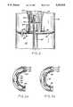
- FIG. 8is an exploded cross-sectional view of a preferred two-piece embodiment of the hygienic cap of the present invention.
- FIG. 9is a composite cross-sectional view of the two-piece cap of FIG. 8, as assembled.
- FIG. 10is an enlarged fragmentary side elevation view of the tip end of a preferred alternative embodiment of the feed tube.
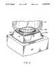
- FIG. 11is an enlarged plan view of the end face of the preferred embodiment of the cap and protective seal covering.
- a bottled water cooler 10including a cabinet 20 of the type having an open-topped cooling reservoir 12 which is disposed to receive the inverted neck of a bottle 15 containing drinking water or other potable liquid.
- the reservoir 12 and its contentsare subjected to temperature control by a refrigeration system and/or a heating system (not shown) in the lower portion of the cabinet 20, and water is taken from the reservoir through a drain pipe 22 and a faucet 13 mounted on a cabinet front panel 14.
- the front panel 14is recessed within the cabinet periphery so as to set the faucet 13 back into the cabinet and thus prevent inadvertent contact.
- a mounting adapter 25is disposed on the upper portion of the water cooler cabinet 20.
- the mounting adapter 25is provided with an annular ring 24 on its upper portion 26 and in order to properly receive and guide the inverted water bottle 15, the mounting adapter 25 is provided with a tapered entry portion 27 extending downwardly and inwardly from the annular ring 24 on the upper portion 26 of the mounting adapter 25.
- the entry portion 27is formed with a lower end 29 having a length greater than the container neck 51, so that substantially all of the weight of the inverted water bottle is supported by the annular ring 24 of the mounting adapter 25 rather than by the water bottle neck.
- the mounting adapter 25is provided with downwardly extending side walls 17 and also includes internal stiffening ribs 28 interconnecting the side walls 17, the raised upper portion 26 and the tapered entry portion 27 so as to support the annular ring 24.
- annular diaphragm element 41coupled to the lower end 29 of the entry portion 27 of the mounting adapter 25 sealingly closes the upper portion of the reservoir 12 and supports an upstanding feed tube 45 whose operation is described in greater detail below.
- the diaphragm/feed tube configuration described abovecarries a flexible peripheral member 43 for sealingly engaging and closing the open end of the reservoir 12.
- a quick disconnect meansis provided having bayonet-type tab fittings 33 on the diaphragm and complementary lugs 34 on the lower end 29 of the entry portion 27 of the mounting adapter 25. As shown in greater detail in FIGS.
- one or more of the bayonet-type tab fittings 33may be provided with centering detent-like dimples 35 for engagement with complementary recesses 36 formed in the upper surface of the lugs 34 to ensure proper engagement of the quick disconnect means. It will be understood, of course, that other suitable attachment means may be provided, as hereinafter described.
- an air filter 30is provided with a filter element 37, having a filter medium removably fitted on the housing 38 of the filter 30.
- a conduit 39is connected to the filter housing 38 and passes via a grommet 47, through the diaphragm element 41, so that air cannot enter the reservoir except by passing through the filter medium.
- a more detailed description of the filter 30can be found in U.S. Pat. No. 4,834,267, issued May 30, 1989 to Schroer et al. and is hereby incorporated by reference. It will also be appreciated with reference to FIG. 1, that the filter 30 may be conveniently located under the raised upper portion 26 of the mounting adapter 25.
- a hygienic cap 50 for a liquid dispensing systemis shown in FIGS. 4a, 4b and 4c.
- a neck portion 51defines a discharge opening through which liquid may dispense.
- hygienic cap 50is provided with a lid portion 53 adapted to overlie and sealingly close the discharge opening defined by the neck 51.
- an annular skirt portion 55 of the cap 50extends axially away from the periphery of the lid portion 53 and is adapted to surround a portion of the neck 51 so as to sealingly retain contact with the neck portion 51 of the water bottle.
- the hygienic cap 50is provided with an axially inwardly extending recess 60 formed integrally with or otherwise connected to the lid portion 53.
- the axially inwardly extending recess 60includes a first annular sleeve portion 62 which is located generally centrally in the lid portion 53 and is preferably integrally connected thereto.
- a second annular plug and recess sealing portion 70is connected to the inner end of the first annular sleeve portion 62 and extends axially inwardly therefrom. As shown in the illustrated embodiment, the second annular plug and recess sealing portion 70 is provided with a closed inner end 71 to fully seal liquid within the inverted water bottle.
- the second annular plug portion 70is preferably integral with the first annular sleeve portion 62 and is connected thereto through a frangible connection 75 in order to allow the plug portion 70 to be axially separated from the sleeve portion 62 upon the forcible insertion of an upstanding probe, preferably in the form of a feed tube 45, into the inwardly extending recess 60 to facilitate the discharge of liquid from the inverted water bottle.
- the frangible connection 75includes an area of the recess which has reduced wall thickness at the inner end of the sleeve 62 where the plug portion 70 is connected thereto. This single piece construction not only reduces assembly time but also avoids separation and loss of the plug portion.
- the cap 50is formed in a single piece.
- the multiple piecesmay thereafter be assembled in a one-piece configuration either by spin welding, sonic welding, chemical bonding or the like.
- the plug portion 70is formed with an internal gripping rib 72.
- feed tube 45is provided with an annular groove 42 formed in its outside surface.
- feed tube 45may be provided with an upper tip portion 44 of reduced diameter and a tapered annular ramp portion 63 adjacent the annular groove 42 for guiding the annular gripping rib 72 into the annular groove 42.
- feed tube 45is formed with an internal bore 46 and at least one radial inlet 48 communicating therewith to allow the dispensing of liquid from the interior of the inverted water bottle to the reservoir 12 as more fully described in the above-mentioned U.S. Pat. No. 4,699,188 to Baker et al.
- the inlet 48is spaced from the end of the feed tube 45 by a distance that is greater than the internal depth of the plug 70.
- the exterior surface of the feed tube 45is dimensioned with respect to the interior of the first annular sleeve portion 62 so that a sealing engagement is effected upon insertion of the feed tube 45 into the recess 60 and the inverted water bottle.
- the hygienic liquid dispensing systemis provided with means for sealing the inverted water bottle upon removal of the water bottle from the cooler or, conversely, upon removal of the feed tube from the hygienic cap 50.
- annular groove 42Upon removal of feed tube 45 from the inverted water bottle 15, annular groove 42 retains the annular plug portion 70 of hygienic cap 50 until the plug and recess sealing portion is fully drawn into the axially inwardly extending recess 60 of lid portion 53.
- the plug portion 70is formed with an outside annular surface dimensioned to sealingly fit within the sleeve portion 62 when the feed tube 45 is withdrawn from the recess 60.
- the plug 70is preferably formed with a tapered lead-in section 69 adjacent the frangible connection 75 for guiding the plug 70 into the sleeve 62 when the feed tube 45 is withdrawn from the recess 60.
- Adjacent its closed end 71, the plug and recess sealing portion 70is also preferably provided with an annular flange 73 in order to prevent the plug and recess portion 70 from being removed from the hygienic cap 60.
- the external annular flange 73is dimensioned to seat on the inner end of the sleeve 62 when the plug and recess sealing 70 is drawn into interfitting engagement with the sleeve Additionally, in order to sealingly engage the plug portion 70 with the first annular sleeve portion 62 of the hygienic cap, plug portion 70 is provided with an external annular recess 77 which sealingly cooperates with a radially inwardly projecting bead 76 of sleeve portion 62.
- this external annular groove/internally projecting bead combinationprovides a gripping means that will allow the feed tube 45 to mate with and retain the plug portion 70 prior to the plug portion becoming slidably disengaged with respect to the sleeve portion 62.
- the hygienic cap 50is also provided with a line of weakness 80 on the skirt 55 extending toward the lid portion 53 and a pull tab 85 extending axially from the skirt. Pull tab 85 is provided to facilitate manually tearing the skirt 55 along the line of weakness 80 when the cap 50 is removed from the container.
- the capis formed to receive a protective seal 84 covering the recess 60 to prevent contaminants from entering therein. The protective seal 84 also serves to indicate whether the cap has been tampered with prior to insertion of the feed tube 45 into the recess 60.
- FIG. 5An alternate embodiment of the invention is illustrated in FIG. 5 wherein the mounting adapter 25a is designed to be positioned on top of an existing water cooler 10a having a flat upper surface.
- the above described hygienic water bottle system having the hygienic cap, feed tube and mounting diaphragmis housed within the cooler 10a, but is not shown here.
- FIG. 6A further alternative and preferred embodiment of the invention is illustrated in FIG. 6 wherein the diaphragm element 41 is detachably secured to the lower end 29 of the entry portion 27 of the mounting adapter 25 by means of a plurality of cap screws or other suitable threaded connectors 87. As shown here and in FIG. 7, four screws 87 are threadably received in recesses 88 located in vertically extending reinforcing ribs 89 formed on the lower end 29 of the mounting adapter 25. Also, in this preferred embodiment, the flexible peripheral sealing member 43 of the diaphragm is formed with an integral upwardly extending tube 90 for receiving the connecting nipple 91 of the air filter unit 30.
- cap 50 of the present inventionmay be made of a two-piece construction, if desired.
- cap 50comprises two parts: the outer shell 50A including the annular skirt portion 55 and the outer annular portion 53A of the lid; and the inner insert portion 50B including the annular plug portion 70, the annular sleeve portion 62, and an annular flange portion 53B which joins the annular portion 53A to complete the lid portion 53 of the assembled cap 50 when the two parts 50A and 50B are joined together.
- bonding techniquesmay be employed such as spin welding, adhesive or chemical bonding, to secure the parts 50A and 50B together, sonic welding is preferred.
- the shell 50Aincludes an axially inwardly disposed annular ledge 54A against which the inner face 54B of the flange 53B of the insert portion 50B is pressed.
- the inner periphery of the ledge 54Ais radiused to mate smoothly with the curvature of the flange 53B where it merges into the outer wall surface of the sleeve portion 62 and the flange 53B includes a raised annular rib 54C which is flattened and sealed against the flange during the sonic welding process.
- FIG. 9A completed hygienic cap 50 with the two pieces 50A and 50B assembled and bonded together is shown in FIG. 9.
- FIG. 10An alternative and preferred embodiment of the feed tube 45 is shown in FIG. 10. As shown here the tip end 44 of the feed tube 45 is provided with a somewhat more rounded or radiused end portion 44A to facilitate easy entrance past the gripping rib 72 and into the inner bore 70A of the plug portion 70.
- the preferred embodiment of the feed tube 45also includes four radial openings 48 spaced axially outwardly from the annular groove 42 in which the gripping rib 72 seats upon insertion of the feed tube 45 into the plug 70. It will also be seen that the tapered annular ramp portion 63A of this preferred embodiment is somewhat longer and more gradually inclined outwardly than the ramp 63 of the feed tube 45 shown in FIGS. 4a-4c.
- FIG. 11An end view of the preferred embodiment of the hygienic cap 50 is shown in FIG. 11 with the protective seal 84 in place covering the outer open end of the recess 60.
- this protective seal 84which prevents dirt and other contaminants from entering the recess 60 during storage and transportation of the bottle or container 15, is removed from the cap 50 just prior to inverting the bottle 15 and installing it in the bottle water cooler 10.
- the seal 84is generally disc-shaped but, desirably, includes a radially extending pull tab 85 to facilitate easy gripping when the seal is pulled from the cap.
- the protective seal 84is secured to the cap 50 by a suitable adhesive that secures the seal 84 firmly in place during storage and transportation but releases readily when the tab 86 is pulled.
- the sealmay be made of treated paper, foil, plastic film or a suitable laminate thereof and, if desired, may be imprinted with an appropriate brand name, company logo, product designation, bar coding or the like.
- the end face of the hygienic cap 50is also provided with a substantially continuous circumferential bead 82 which defines a recessed area for the protective seal 84 and helps prevent it from being accidentally scraped off.
Landscapes
- Engineering & Computer Science (AREA)
- Mechanical Engineering (AREA)
- Closures For Containers (AREA)
Abstract
Description
Claims (10)
Priority Applications (1)
| Application Number | Priority Date | Filing Date | Title |
|---|---|---|---|
| US08/058,564US5295518A (en) | 1988-10-14 | 1993-05-06 | Two-piece hygienic cap with resealable plug and tearable skirt with pull tab |
Applications Claiming Priority (3)
| Application Number | Priority Date | Filing Date | Title |
|---|---|---|---|
| US25762788A | 1988-10-14 | 1988-10-14 | |
| US07/684,597US5222530A (en) | 1988-10-14 | 1991-04-12 | Hygienic cap and liquid dispensing system |
| US08/058,564US5295518A (en) | 1988-10-14 | 1993-05-06 | Two-piece hygienic cap with resealable plug and tearable skirt with pull tab |
Related Parent Applications (1)
| Application Number | Title | Priority Date | Filing Date |
|---|---|---|---|
| US07/684,597ContinuationUS5222530A (en) | 1988-10-14 | 1991-04-12 | Hygienic cap and liquid dispensing system |
Publications (1)
| Publication Number | Publication Date |
|---|---|
| US5295518Atrue US5295518A (en) | 1994-03-22 |
Family
ID=46247332
Family Applications (1)
| Application Number | Title | Priority Date | Filing Date |
|---|---|---|---|
| US08/058,564Expired - LifetimeUS5295518A (en) | 1988-10-14 | 1993-05-06 | Two-piece hygienic cap with resealable plug and tearable skirt with pull tab |
Country Status (1)
| Country | Link |
|---|---|
| US (1) | US5295518A (en) |
Cited By (32)
| Publication number | Priority date | Publication date | Assignee | Title |
|---|---|---|---|---|
| US5464127A (en)* | 1994-02-28 | 1995-11-07 | Ebtech, Inc. | Sealed actuator probe assembly for a bottled water station |
| US5533651A (en)* | 1994-12-12 | 1996-07-09 | Eddy; John W. | Universal adapter for liquid dispensers |
| US5636771A (en)* | 1995-06-06 | 1997-06-10 | International Paper Company | Frangible pour spout fitment |
| US5694991A (en)* | 1994-03-31 | 1997-12-09 | Eastman Kodak Company | Valve assemblage and method of use |
| EP0816283A1 (en)* | 1996-07-03 | 1998-01-07 | Walter E. Hidding | Protective tamper-evident label and bottle cap |
| US6029860A (en)* | 1993-10-20 | 2000-02-29 | Elkay Manufacturing Company | Liquid dispensing device and hygienic adapter |
| US6061681A (en)* | 1997-06-30 | 2000-05-09 | Movo Media, Inc. | On-line dating service for locating and matching people based on user-selected search criteria |
| US6619511B2 (en) | 2001-02-08 | 2003-09-16 | Oasis Corporation | Feed tube adapter for a bottled water cooler |
| US20040193082A1 (en)* | 2003-03-28 | 2004-09-30 | Cofre Ruth P. | Dynamic position adjustment device for portions of the human body |
| US20050224446A1 (en)* | 2004-04-08 | 2005-10-13 | Crealise Packaging-Conditionnement Inc. | Cap and closure system for closing a large potable liquid bottle |
| US20050224133A1 (en)* | 2004-12-29 | 2005-10-13 | George Yui | Receptacle assembly for bottled water dispenser |
| US20060016777A1 (en)* | 2004-07-22 | 2006-01-26 | Hidding Douglas J | Probe actuated bottle cap |
| US20070023383A1 (en)* | 2004-04-08 | 2007-02-01 | Crealise Packaging-Conditionnement Inc. | Threadless cap with a nonintegral seal |
| US20070267100A1 (en)* | 2006-05-08 | 2007-11-22 | Spear Gregory N | Bottle Cap and Method of Use With a Liquid Dispensing Apparatus and System |
| US20080054017A1 (en)* | 2006-08-30 | 2008-03-06 | Mtn Products, Inc. | Liquid Dispensing Apparatus and System |
| US20080053564A1 (en)* | 2006-08-30 | 2008-03-06 | Mtn Products, Inc. | Bottom Load Water Cooler |
| US20080135512A1 (en)* | 2006-12-11 | 2008-06-12 | International Plastics And Equipment Corp. | Closure |
| USD582194S1 (en) | 2007-11-13 | 2008-12-09 | Mtn Products, Inc. | Water cooler |
| US20090012485A1 (en)* | 2007-03-23 | 2009-01-08 | Michaels Thomas L | Fluid collection and disposal system having interchangeable collection and other features and methods relating thereto |
| US20090277535A1 (en)* | 2006-08-30 | 2009-11-12 | Mtn Products, Inc. | Bottom load water cooler |
| US20090308834A1 (en)* | 2006-04-28 | 2009-12-17 | Tokan Kogyo Co., Ltd | Cap and covered container |
| USD608129S1 (en) | 2008-03-10 | 2010-01-19 | MTN Products, Inc | Water cooler |
| USD617132S1 (en) | 2009-09-08 | 2010-06-08 | Mtn Products, Inc. | Water cooler |
| USD623885S1 (en) | 2009-06-18 | 2010-09-21 | Mtn Products, Inc. | Water cooler |
| US20110056981A1 (en)* | 2009-09-09 | 2011-03-10 | Mtn Products, Inc. | Energy saving baffle for water cooler |
| US20110118680A1 (en)* | 2009-07-15 | 2011-05-19 | Cardinal Health, Inc. | Fluid collection and disposal system and related methods |
| US20110178482A1 (en)* | 2007-03-23 | 2011-07-21 | Cardinal Health, Inc. | Fluid collection and disposal system and related methods |
| USD642849S1 (en) | 2010-04-28 | 2011-08-09 | MTN Products, Inc | Water cooler |
| USD643239S1 (en) | 2010-04-28 | 2011-08-16 | MTN Products, Inc | Water cooler |
| US8025173B2 (en) | 2006-09-07 | 2011-09-27 | Allegiance Corporation | Collapsible canister liner for medical fluid collection |
| USD677509S1 (en) | 2011-09-23 | 2013-03-12 | MTN Products, Inc | Water cooler |
| USD688079S1 (en) | 2012-02-21 | 2013-08-20 | Chun Yen Wang | Combination water dispenser and beverage brewer |
Citations (17)
| Publication number | Priority date | Publication date | Assignee | Title |
|---|---|---|---|---|
| US497896A (en)* | 1893-05-23 | The morris petxss co | ||
| US996127A (en)* | 1910-06-09 | 1911-06-27 | Atwood L Boggs | Liquid-cooler. |
| US1248705A (en)* | 1915-10-26 | 1917-12-04 | George D Pogue | Container for drinking-water. |
| US2057238A (en)* | 1934-11-05 | 1936-10-13 | Philip P Krug | Liquid-dispensing apparatus |
| CA631376A (en)* | 1961-11-21 | R. Schultz Wilfred | Combined hot and cold fluid dispensing apparatus | |
| US3812992A (en)* | 1970-02-02 | 1974-05-28 | American Flange & Mfg | Infant feeding package |
| US3893599A (en)* | 1972-10-25 | 1975-07-08 | Cornelius Co | Means for dispensing |
| US3955682A (en)* | 1973-03-28 | 1976-05-11 | Accurate Wirecraft Company | Laboratory shelf for funnel-shaped glassware |
| US4239130A (en)* | 1979-04-18 | 1980-12-16 | Altadonna Lawrence J | Oil caddy |
| US4391308A (en)* | 1981-04-16 | 1983-07-05 | Steiner Corporation | Soap dispensing system |
| US4523698A (en)* | 1984-01-27 | 1985-06-18 | W. Duncan Porter | Beer keg accessories |
| US4597423A (en)* | 1985-03-26 | 1986-07-01 | Chenot Gary D | Device for opening bottled water containers |
| USRE32354E (en)* | 1980-07-21 | 1987-02-17 | Scholle Corporation | Container for holding and dispensing fluid |
| US4699188A (en)* | 1986-01-17 | 1987-10-13 | Baker Henry E | Hygienic liquid dispensing system |
| US4834267A (en)* | 1987-11-02 | 1989-05-30 | Elkay Manufacturing Company | Bottled water cooler air filter |
| US4874023A (en)* | 1988-09-30 | 1989-10-17 | Liqui-Box Corporation | Decap dispensing system for water cooler bottles |
| US5232125A (en)* | 1991-10-08 | 1993-08-03 | Portola Packaging, Inc. | Non-spill bottle cap used with water dispensers |
- 1993
- 1993-05-06USUS08/058,564patent/US5295518A/ennot_activeExpired - Lifetime
Patent Citations (17)
| Publication number | Priority date | Publication date | Assignee | Title |
|---|---|---|---|---|
| US497896A (en)* | 1893-05-23 | The morris petxss co | ||
| CA631376A (en)* | 1961-11-21 | R. Schultz Wilfred | Combined hot and cold fluid dispensing apparatus | |
| US996127A (en)* | 1910-06-09 | 1911-06-27 | Atwood L Boggs | Liquid-cooler. |
| US1248705A (en)* | 1915-10-26 | 1917-12-04 | George D Pogue | Container for drinking-water. |
| US2057238A (en)* | 1934-11-05 | 1936-10-13 | Philip P Krug | Liquid-dispensing apparatus |
| US3812992A (en)* | 1970-02-02 | 1974-05-28 | American Flange & Mfg | Infant feeding package |
| US3893599A (en)* | 1972-10-25 | 1975-07-08 | Cornelius Co | Means for dispensing |
| US3955682A (en)* | 1973-03-28 | 1976-05-11 | Accurate Wirecraft Company | Laboratory shelf for funnel-shaped glassware |
| US4239130A (en)* | 1979-04-18 | 1980-12-16 | Altadonna Lawrence J | Oil caddy |
| USRE32354E (en)* | 1980-07-21 | 1987-02-17 | Scholle Corporation | Container for holding and dispensing fluid |
| US4391308A (en)* | 1981-04-16 | 1983-07-05 | Steiner Corporation | Soap dispensing system |
| US4523698A (en)* | 1984-01-27 | 1985-06-18 | W. Duncan Porter | Beer keg accessories |
| US4597423A (en)* | 1985-03-26 | 1986-07-01 | Chenot Gary D | Device for opening bottled water containers |
| US4699188A (en)* | 1986-01-17 | 1987-10-13 | Baker Henry E | Hygienic liquid dispensing system |
| US4834267A (en)* | 1987-11-02 | 1989-05-30 | Elkay Manufacturing Company | Bottled water cooler air filter |
| US4874023A (en)* | 1988-09-30 | 1989-10-17 | Liqui-Box Corporation | Decap dispensing system for water cooler bottles |
| US5232125A (en)* | 1991-10-08 | 1993-08-03 | Portola Packaging, Inc. | Non-spill bottle cap used with water dispensers |
Cited By (50)
| Publication number | Priority date | Publication date | Assignee | Title |
|---|---|---|---|---|
| US6029860A (en)* | 1993-10-20 | 2000-02-29 | Elkay Manufacturing Company | Liquid dispensing device and hygienic adapter |
| US6123232A (en)* | 1993-10-20 | 2000-09-26 | Elkay Manufacturing Company | Liquid dispensing device and hygienic adapter therefor |
| US5464127A (en)* | 1994-02-28 | 1995-11-07 | Ebtech, Inc. | Sealed actuator probe assembly for a bottled water station |
| US5694991A (en)* | 1994-03-31 | 1997-12-09 | Eastman Kodak Company | Valve assemblage and method of use |
| US5533651A (en)* | 1994-12-12 | 1996-07-09 | Eddy; John W. | Universal adapter for liquid dispensers |
| US5636771A (en)* | 1995-06-06 | 1997-06-10 | International Paper Company | Frangible pour spout fitment |
| KR100444595B1 (en)* | 1996-07-03 | 2004-12-08 | 블랙호크 모닝 컴퍼니 인코포레이티드 | Protective tamper-evident label and bottle cap |
| EP0816283A1 (en)* | 1996-07-03 | 1998-01-07 | Walter E. Hidding | Protective tamper-evident label and bottle cap |
| CN1099984C (en)* | 1996-07-03 | 2003-01-29 | 沃尔特·E·希丁 | Protective tear-off labels and caps |
| US6061681A (en)* | 1997-06-30 | 2000-05-09 | Movo Media, Inc. | On-line dating service for locating and matching people based on user-selected search criteria |
| US6619511B2 (en) | 2001-02-08 | 2003-09-16 | Oasis Corporation | Feed tube adapter for a bottled water cooler |
| US20040193082A1 (en)* | 2003-03-28 | 2004-09-30 | Cofre Ruth P. | Dynamic position adjustment device for portions of the human body |
| US20050224446A1 (en)* | 2004-04-08 | 2005-10-13 | Crealise Packaging-Conditionnement Inc. | Cap and closure system for closing a large potable liquid bottle |
| US20070023383A1 (en)* | 2004-04-08 | 2007-02-01 | Crealise Packaging-Conditionnement Inc. | Threadless cap with a nonintegral seal |
| US8177083B2 (en) | 2004-04-08 | 2012-05-15 | Tetra Laval Holdings & Finance S.A. | Threadless cap with a nonintegral seal |
| US7581653B2 (en) | 2004-04-08 | 2009-09-01 | Crealise Packaging-Conditionnement Inc. | Cap and closure system for closing a large potable liquid bottle |
| US20060016777A1 (en)* | 2004-07-22 | 2006-01-26 | Hidding Douglas J | Probe actuated bottle cap |
| US7350656B2 (en)* | 2004-07-22 | 2008-04-01 | Blackhawk Molding Co., Inc. | Probe actuated bottle cap |
| US20050224133A1 (en)* | 2004-12-29 | 2005-10-13 | George Yui | Receptacle assembly for bottled water dispenser |
| US8496129B2 (en) | 2006-04-28 | 2013-07-30 | Tokan Kogyo Co, Ltd. | Cap and covered container |
| US8235232B2 (en)* | 2006-04-28 | 2012-08-07 | Tokan Kogyo Co., Ltd. | Cap and covered container |
| US20090308834A1 (en)* | 2006-04-28 | 2009-12-17 | Tokan Kogyo Co., Ltd | Cap and covered container |
| US20070267100A1 (en)* | 2006-05-08 | 2007-11-22 | Spear Gregory N | Bottle Cap and Method of Use With a Liquid Dispensing Apparatus and System |
| US20090277535A1 (en)* | 2006-08-30 | 2009-11-12 | Mtn Products, Inc. | Bottom load water cooler |
| US7434603B2 (en) | 2006-08-30 | 2008-10-14 | Mtn Products, Inc. | Bottom load water cooler |
| US20080054017A1 (en)* | 2006-08-30 | 2008-03-06 | Mtn Products, Inc. | Liquid Dispensing Apparatus and System |
| US8281821B2 (en) | 2006-08-30 | 2012-10-09 | MTN Products, Inc | Leak stop seal for water cooler |
| US20080053564A1 (en)* | 2006-08-30 | 2008-03-06 | Mtn Products, Inc. | Bottom Load Water Cooler |
| US8025173B2 (en) | 2006-09-07 | 2011-09-27 | Allegiance Corporation | Collapsible canister liner for medical fluid collection |
| US9770540B2 (en) | 2006-09-07 | 2017-09-26 | Allegiance Corporation | Collapsible canister liner for medical fluid collection |
| US7886921B2 (en)* | 2006-12-11 | 2011-02-15 | International Plastics And Equipment Corp. | Closure |
| US20080135512A1 (en)* | 2006-12-11 | 2008-06-12 | International Plastics And Equipment Corp. | Closure |
| US20110178482A1 (en)* | 2007-03-23 | 2011-07-21 | Cardinal Health, Inc. | Fluid collection and disposal system and related methods |
| US10252856B2 (en) | 2007-03-23 | 2019-04-09 | Allegiance Corporation | Fluid collection and disposal system having interchangeable collection and other features and methods relating thereof |
| US9889239B2 (en) | 2007-03-23 | 2018-02-13 | Allegiance Corporation | Fluid collection and disposal system and related methods |
| US20090012485A1 (en)* | 2007-03-23 | 2009-01-08 | Michaels Thomas L | Fluid collection and disposal system having interchangeable collection and other features and methods relating thereto |
| US9604778B2 (en) | 2007-03-23 | 2017-03-28 | Allegiance Corporation | Fluid collection and disposal system having interchangeable collection and other features and methods relating thereto |
| US8500706B2 (en) | 2007-03-23 | 2013-08-06 | Allegiance Corporation | Fluid collection and disposal system having interchangeable collection and other features and methods relating thereto |
| USD582194S1 (en) | 2007-11-13 | 2008-12-09 | Mtn Products, Inc. | Water cooler |
| USD608129S1 (en) | 2008-03-10 | 2010-01-19 | MTN Products, Inc | Water cooler |
| USD623885S1 (en) | 2009-06-18 | 2010-09-21 | Mtn Products, Inc. | Water cooler |
| US20110118680A1 (en)* | 2009-07-15 | 2011-05-19 | Cardinal Health, Inc. | Fluid collection and disposal system and related methods |
| US8460256B2 (en) | 2009-07-15 | 2013-06-11 | Allegiance Corporation | Collapsible fluid collection and disposal system and related methods |
| USD617132S1 (en) | 2009-09-08 | 2010-06-08 | Mtn Products, Inc. | Water cooler |
| US8356731B2 (en) | 2009-09-09 | 2013-01-22 | Mtn Products Inc | Energy saving baffle for water cooler |
| US20110056981A1 (en)* | 2009-09-09 | 2011-03-10 | Mtn Products, Inc. | Energy saving baffle for water cooler |
| USD643239S1 (en) | 2010-04-28 | 2011-08-16 | MTN Products, Inc | Water cooler |
| USD642849S1 (en) | 2010-04-28 | 2011-08-09 | MTN Products, Inc | Water cooler |
| USD677509S1 (en) | 2011-09-23 | 2013-03-12 | MTN Products, Inc | Water cooler |
| USD688079S1 (en) | 2012-02-21 | 2013-08-20 | Chun Yen Wang | Combination water dispenser and beverage brewer |
Similar Documents
| Publication | Publication Date | Title |
|---|---|---|
| US5289854A (en) | Two-piece hygienic cap and opening probe or feed tube | |
| US5295519A (en) | Hygienic liquid dispensing system including feed tube or probe for opening and resealing coaxial cap | |
| US5121778A (en) | Liquid container support and hygienic liquid dispensing system | |
| US5295518A (en) | Two-piece hygienic cap with resealable plug and tearable skirt with pull tab | |
| US5289855A (en) | Liquid container support and probe-type hygienic liquid dispensing system | |
| US5222531A (en) | Liquid container support and hygienic liquid dispensing system | |
| CA1291969C (en) | Hygienic liquid dispensing system | |
| US7306723B2 (en) | Method and apparatus for water purification | |
| EP0569584B1 (en) | bottled water station | |
| US5259534A (en) | Container cap with removable insert | |
| US5518143A (en) | Container cap and assembly for sipping liquids | |
| KR100377054B1 (en) | Two-part coupling structure that flows fluid upon connection and seals again when disconnected | |
| US5676278A (en) | Water dispensing feed tube with improved flow | |
| EP1456113B1 (en) | Feed tube for use in a liquid delivery system | |
| EP3079990B1 (en) | A capping assembly for closing a fluid container | |
| EP0129711B1 (en) | Improvements relating to liquid dispensing | |
| CN101027245A (en) | A dispensing line for a dispensing system | |
| CA1338339C (en) | Liquid container support and hygienic liquid dispensing system | |
| US20050224133A1 (en) | Receptacle assembly for bottled water dispenser | |
| JP2025523766A (en) | Beverage delivery line connector | |
| GB2337250A (en) | Adaptor for a dispensing device |
Legal Events
| Date | Code | Title | Description |
|---|---|---|---|
| STPP | Information on status: patent application and granting procedure in general | Free format text:APPLICATION UNDERGOING PREEXAM PROCESSING | |
| CC | Certificate of correction | ||
| FPAY | Fee payment | Year of fee payment:4 | |
| AS | Assignment | Owner name:SUNROC CORPORATION, DELAWARE Free format text:ASSIGNMENT OF ASSIGNORS INTEREST;ASSIGNOR:LASALLE BUSINESS CREDIT, INC.;REEL/FRAME:012083/0380 Effective date:20010412 | |
| FPAY | Fee payment | Year of fee payment:8 | |
| FEPP | Fee payment procedure | Free format text:PAYOR NUMBER ASSIGNED (ORIGINAL EVENT CODE: ASPN); ENTITY STATUS OF PATENT OWNER: LARGE ENTITY | |
| AS | Assignment | Owner name:SUNROC LLC, DELAWARE Free format text:ASSIGNMENT OF ASSIGNORS INTEREST;ASSIGNOR:SUNROC CORPORATION;REEL/FRAME:015251/0719 Effective date:20030929 | |
| AS | Assignment | Owner name:HARRIS TRUST AND SAVINGS BANK AS ADMINISTRATIVE AG Free format text:SECURITY INTEREST;ASSIGNOR:SUNROC LLC;REEL/FRAME:015259/0144 Effective date:20041012 | |
| AS | Assignment | Owner name:CONGRESS FINANCIAL CORPORATION (CENTRAL), ILLINOIS Free format text:SECURITY AGREEMENT;ASSIGNOR:SUNROC LLC;REEL/FRAME:016345/0937 Effective date:20050210 | |
| AS | Assignment | Owner name:SUNROC LLC, DELAWARE Free format text:RELEASE OF SECURITY INTEREST;ASSIGNOR:HARRIS TRUST AND SAVINGS BANK, AS AGENT;REEL/FRAME:016345/0930 Effective date:20050210 | |
| FPAY | Fee payment | Year of fee payment:12 | |
| AS | Assignment | Owner name:LVD ACQUISITION, LLC, OHIO Free format text:ASSIGNMENT OF ASSIGNORS INTEREST;ASSIGNOR:ZOHAR WATERWORKS LLC;REEL/FRAME:022846/0960 Effective date:20090601 | |
| AS | Assignment | Owner name:PATRIARCH PARTNERS AGENCY SERVICES, LLC,NEW YORK Free format text:SECURITY AGREEMENT;ASSIGNOR:LVD ACQUISITION, LLC;REEL/FRAME:024233/0787 Effective date:20090601 | |
| AS | Assignment | Owner name:LVD ACQUISITION, LLC, OHIO Free format text:TERMINATION AND RELEASE OF SECURITY INTEREST IN INTELLECTUAL PROPERTY;ASSIGNOR:ANKURA TRUST COMPANY, LLC, AS SUCCESSOR AGENT TO PATRIARCH PARTNERS AGENCY SERVICES, LLC;REEL/FRAME:050593/0691 Effective date:20190930 |