US5295242A - Apparatus and method for viewing relationships in a factory management system - Google Patents
Apparatus and method for viewing relationships in a factory management systemDownload PDFInfo
- Publication number
- US5295242A US5295242AUS07/608,310US60831090AUS5295242AUS 5295242 AUS5295242 AUS 5295242AUS 60831090 AUS60831090 AUS 60831090AUS 5295242 AUS5295242 AUS 5295242A
- Authority
- US
- United States
- Prior art keywords
- objects
- factory
- class
- icon
- displaying
- Prior art date
- Legal status (The legal status is an assumption and is not a legal conclusion. Google has not performed a legal analysis and makes no representation as to the accuracy of the status listed.)
- Expired - Lifetime
Links
Images


Classifications
- G—PHYSICS
- G06—COMPUTING OR CALCULATING; COUNTING
- G06F—ELECTRIC DIGITAL DATA PROCESSING
- G06F3/00—Input arrangements for transferring data to be processed into a form capable of being handled by the computer; Output arrangements for transferring data from processing unit to output unit, e.g. interface arrangements
- G06F3/01—Input arrangements or combined input and output arrangements for interaction between user and computer
- G06F3/048—Interaction techniques based on graphical user interfaces [GUI]
- G06F3/0481—Interaction techniques based on graphical user interfaces [GUI] based on specific properties of the displayed interaction object or a metaphor-based environment, e.g. interaction with desktop elements like windows or icons, or assisted by a cursor's changing behaviour or appearance
- G—PHYSICS
- G06—COMPUTING OR CALCULATING; COUNTING
- G06F—ELECTRIC DIGITAL DATA PROCESSING
- G06F3/00—Input arrangements for transferring data to be processed into a form capable of being handled by the computer; Output arrangements for transferring data from processing unit to output unit, e.g. interface arrangements
- G06F3/01—Input arrangements or combined input and output arrangements for interaction between user and computer
- G06F3/048—Interaction techniques based on graphical user interfaces [GUI]
- G06F3/0484—Interaction techniques based on graphical user interfaces [GUI] for the control of specific functions or operations, e.g. selecting or manipulating an object, an image or a displayed text element, setting a parameter value or selecting a range
- G06F3/0485—Scrolling or panning
- G06F3/04855—Interaction with scrollbars
- G—PHYSICS
- G06—COMPUTING OR CALCULATING; COUNTING
- G06Q—INFORMATION AND COMMUNICATION TECHNOLOGY [ICT] SPECIALLY ADAPTED FOR ADMINISTRATIVE, COMMERCIAL, FINANCIAL, MANAGERIAL OR SUPERVISORY PURPOSES; SYSTEMS OR METHODS SPECIALLY ADAPTED FOR ADMINISTRATIVE, COMMERCIAL, FINANCIAL, MANAGERIAL OR SUPERVISORY PURPOSES, NOT OTHERWISE PROVIDED FOR
- G06Q10/00—Administration; Management
- G06Q10/06—Resources, workflows, human or project management; Enterprise or organisation planning; Enterprise or organisation modelling
- Y—GENERAL TAGGING OF NEW TECHNOLOGICAL DEVELOPMENTS; GENERAL TAGGING OF CROSS-SECTIONAL TECHNOLOGIES SPANNING OVER SEVERAL SECTIONS OF THE IPC; TECHNICAL SUBJECTS COVERED BY FORMER USPC CROSS-REFERENCE ART COLLECTIONS [XRACs] AND DIGESTS
- Y10—TECHNICAL SUBJECTS COVERED BY FORMER USPC
- Y10S—TECHNICAL SUBJECTS COVERED BY FORMER USPC CROSS-REFERENCE ART COLLECTIONS [XRACs] AND DIGESTS
- Y10S715/00—Data processing: presentation processing of document, operator interface processing, and screen saver display processing
- Y10S715/961—Operator interface with visual structure or function dictated by intended use
- Y10S715/965—Operator interface with visual structure or function dictated by intended use for process control and configuration
- Y10S715/97—Instrumentation and component modelling, e.g. interactive control panel
Definitions
- the present inventionrelates to a system for factory management. More particularly, this invention relates to an interface used for monitoring of factory objects in an object-oriented factory management system.
- Management of a factory which manufactures a product such as semiconductors or aircraft for examplerequires monitoring the status of all aspects in the factory, including raw materials on hand, components, labor resources, and machinery at every step of the manufacturing process. Also, in order to maintain a full range of information regarding partially completed products, a scheme for monitoring manufacturing will also maintain a list of current works in progress. The maintaining of such information allows a manager to determine whether his resources are being used at their full potential, and whether stores of raw materials should be replenished. It also allows a factory supervisor to determine the status of a customer's order and allow for scheduling of critical resources such as labor and machinery.
- One of the objects of the present inventionis to provide a clear representation of the organization of objects in a factory for access and manipulation by a user.
- Another object of the present inventionis to provide a system which clearly illustrates to a user the organization of the factory.
- Another object of the present inventionis to provide a system which displays a factory in such a way that a user of the system can easily monitor resources, raw materials and components in the manufacturing process.
- a method and apparatus for displaying the relationship of objects in a factory on a computer system displayby displaying a first icon, the first icon representing a first class of factory objects.
- the first classmay be a factory, for example.
- a second iconis displayed, the second icon representing a second class of factory objects.
- the second classmay be work areas in a factory.
- a first connector connecting the first icon and second iconis displayed representing the relationship between the first and the second class of factory objects. Then, the first icon is selected, thus displaying a first list of names of all objects comprising the first class of factory objects, such as factory names in a particular embodiment.
- the second list of namescomprises the names of all objects in the second class of factory objects associated with the object from the first class having the first name.
- the second list of namescomprises all work areas in the particular factory selected.
- other factory objectsmay be displayed such as items, work orders, components, scripts, test plans, work cells, work stations, storage areas, machines, and labor, among others.
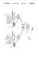
- FIG. 1shows a block diagram of the structure of the factory management system of the preferred embodiment.
- FIG. 2shows the organization of factory object classes in the preferred embodiment.
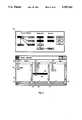
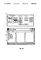
- FIG. 3shows the browser interface of the preferred embodiment.
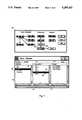
- FIG. 4shows selecting an object icon and populating a column of the browser window.
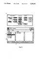
- FIG. 5shows populating a second column by selecting an item name in the first column.
- FIGS. 6 and 7show populating additional columns by selecting object names and columns in the browser window.
- FIG. 8shows how work stations may feed storage areas and vice-versa.
- FIG. 9shows how work stations may feed other work stations in the preferred embodiment.
- FIG. 10shows how a storage area may feed into another storage area in the preferred embodiment.
- FIG. 11ashows populating the browser window with an Item object from the Process Configuration section of the browser map.
- FIG. 11bshows a selected icon of a second object class with the second column heading filled in.
- FIG. 12shows populating a second column by selecting an item name from the first column of the browser.
- FIGS. 13 and 14show various pull down menu options which are available on the browser window.
- a factory floor management system 100is shown.
- Two users 101 and 102may be active upon system 100 and communicate on system 100 through terminals 111 and 112.
- User 101may be communicating on system 100 via terminal 111 and user 102 may be communicating information on system 100 via terminal 112.
- On terminals 111 and 112various commands may be entered by users 101 and 102, or, alternatively, information may be monitored.
- Each terminal 111 and 112comprise a keyboard, 125 and 126 respectively, and cursor controls 123 and 124 respectively for inputting information into terminals 111 and 112. Cursor controls 123 and 124 are used for moving and selecting information on terminal screens 111 and 122.
- Cursor controls 123 and 124are mouse input devices in the preferred embodiment, but in an alternative embodiment may be some other type of cursor control, such as a trackball or joystick, for example.
- each mouse 123 and 124comprises two selection buttons (131 and 132 for device 123, 133 and 134 for device 124) for "selecting" regions on screens 111 and 112. Selection is done by depressing one of the buttons on the corresponding input device.
- One of the buttonsfor the purposes of the remainder of this application, is known as "MB1" (mouse button 1) and the other is known as "MB2" (mouse button 2).
- Either the right or left button on the input devicemay be configured, in the preferred embodiment, as the primary selection button "MB1.”
- button 131may be set up as “MB1” and 132 may be "MB2.”
- the selection button assignmentmay be reversed.
- Each of the input devices 111 and 112are coupled to their corresponding server devices 121 and 122. These provide an interface to the remainder of system 100 from each respective input device.
- Terminal servers 121 and 122are coupled to a file server 130 which provides access to a database 140 containing the information regarding factory objects in the factory configured in the preferred embodiment.
- Each node on system 100such as terminals 111 and 112 may be an X-terminal and each of their corresponding servers shown as 121 and 122, may be one of the VAX family of computers manufactured by Digital Equipment Corporation (DEC) of Waltham, Mass.
- servers 121 and 122are one of the VAX 4000 or 3100 series of work stations.
- servers 121 and 122are running the VMS operating system also manufactured by DEC Computers of Waltham, Mass.
- Each serverruns the "DEC-Windows" user interface environment as a shell which allows relatively easy user interaction on system 100. The preferred embodiment is implemented using this the "DEC-Windows" user interface shell.
- System 100 of the preferred embodimentutilizes a "object-oriented" approach to structuring the factory environment.
- Each of the resources in the systemis considered an object which may be viewed, manipulated or linked with other objects in the system. Attributes may be changed for each object, and objects may be associated with other objects.
- a general layout of the objects used in the preferred embodimentis shown in FIG. 2.
- FIG. 2Also shown in FIG. 2 is each of the objects' relationships with respect to one another. For simplicity, however, certain relationships have not been shown.
- an item 201(a product which is produced by the factory) is linked with a work order 210, components 211, script 212, and test plan 202.
- An itemmay be a component of a larger item to be manufactured, or it may be a finished product produced from raw materials.
- An item 201in order to be manufactured, must have a work order 210 associated with it.
- Work order 210will contain such information as when manufacturing is or will be started on the item, and/or when the item was completed. Work order 210 might also contain such information as the number of items which were or are required to be manufactured.
- An itemmay also be linked with such information as resources required, such as labor or machinery (see objects 230 and 231) or other information which is required to manufacture item 201.
- an itemmay have a components object 211 associated with it.
- a components objectmay include a list of other items which comprise an item 201. Alternatively, it may have a list of raw materials (which are also set up as items) which comprise 201.
- item 201may have a script 212 associated with it. Script 212 is basically a series of commands and/or instructions which are associated with the production of the item. This information includes directions to an operator of a particular machine manufacturing the item, and/or specific operations which must be performed at each step of the manufacturing process to produce the item.
- item 201is linked with a test plan 202, which is a series of instructions and/or operations within system 100 which must be performed to indicate whether item 201 meets certain minimum standards to operate within tolerances. For instance, a quality assurance program may be utilized in system 100.
- One such systemis known as the RS/1 quality management system manufactured by BBN Software Products Corporation of Cambridge, Mass., and may operate on servers 121 or 122.
- the preferred embodimentalso allows the structure of the factory to be defined.
- the layout of the factoryis done in a hierarchical fashion (as opposed to the relationships in the Process Configuration section). That is, parent units represent larger portions of the factory and child objects represent smaller areas in the factory.
- FIG. 2This is also graphically represented in FIG. 2.
- factory 220resides at the highest level in the Factory Layout hierarchy.
- the child of factory 220is work center 221.
- Work center 221may be thought of a subset of a factory in which a certain set of functions are performed.
- work cell 222is an area of work center 221 in which specific functions are performed.
- Work station 223is a particular machine or place in which either an individual or a limited number of individuals perform one given task. Coupled to work station 223, is storage area 224. When items are completed at a work station 223 they are typically put into a storage area. Storage areas may feed into work stations, work stations may feed into storage areas or each of these may feed into another object having the same class (e.g. work station to work station or storage area to storage area).
- the preferred embodimentalso provides a list of objects known as "Resources.”
- Resources in this model of the preferred embodimentinclude labor 230, machine 231 and 224.
- Labor 230is an object which indicates the type of labor resources available in the factory.
- Labor 230includes each employee and the number of hours (man hours) available for that employee to work and whether the employee is available to work (e.g. is at the factory).
- Labormay also indicate the skills of each employee, since certain employees may not be qualified to work with certain equipment or at certain work stations. Therefore, types of labor may be delineated within the factory environment.
- Machine 231is another resource and functions similarly to labor 230. Machines are used for manufacturing items in the factory. Each machine may be categorized by qualification (such as whether the machine may manufacture a particular type of item and its capacity). Each machine object may also have status indicators such as whether the machine is currently operating or is in a maintenance mode and therefore unavailable. Such a status indicator may also indicate that a particular machine is idle and thus available for use.
- qualificationsuch as whether the machine may manufacture a particular type of item and its capacity
- Each machine objectmay also have status indicators such as whether the machine is currently operating or is in a maintenance mode and therefore unavailable. Such a status indicator may also indicate that a particular machine is idle and thus available for use.
- FIG. 3shows the "Browser" display screen 300 which allows various objects in the system of the preferred embodiment to be viewed on a user terminal such as 111 or 112.
- the window shown as 302 in FIG. 3is the "Setup Browser” interface used for defining objects in the system.
- window 301is a graphical representation on a computer screen of the structure and relationship of the objects which were discussed with reference to FIG. 2.
- the graphical representation of the objects on window 301is useful for viewing and defining relationships between objects using interface 302 on screen 300.
- Window 301also contains the "buttons” "OK” 310, "Cancel” 311 and "Help" 312.
- “Buttons”are areas in a user interface screen which, when “selected,” cause a specific function to occur. Selection is done by moving a cursor such as 390 using an input device such as 122 or 124 on FIG. 1 to that area of the screen and depressing a button, such as MB1. "OK” 310 is selected using cursor 390 shown in FIG. 3 when an operation has been indicated on the display that the user wishes to perform. "Cancel” 311 is selected using cursor 390 when an operation has been initiated that the user now wishes to abort. Finally, window 301 comprises a "Help" button 312 which is selected using cursor 390 if a user desires additional information on a function provided by screen 301.
- window 302comprises three currently displayed columns 352, 344, and 348.
- Each of the columnswill contain named objects within an object class once an icon for the class has been selected in a certain manner on window 301.
- Each of the displayed columnshas a header field 332, 333 or 334 associated with it which displays the name of the class of the objects which are shown in the corresponding column. If there are more objects than is possible to show on the column of browser window 302, then the remainder of the objects are not displayed and may be viewed by selecting down arrows 355, 358 or 361 causing the corresponding column to "scroll" downward.
- Right arrows 343, 347 and 351work in a similar manner for object names that extend to the right of the currently displayed information in each column.
- Sliders 342, 346 and 350work in a similar manner to sliders 354, 357 or 360 but in the horizontal directions shown in FIG. 3.
- window slider 339 and arrows 338 and 340work in a similar manner to the other sliders but are used for displaying additional columns not currently displayed on window 302. In other words, if there is a column to the left of the column currently displayed in window 302, then left arrow 338 may be selected and the next left column will be displayed.
- Right arrow 340works in the right direction in FIG. 3 for columns that a user wishes to display.
- Slider 339will work in either direction when the user selects it and moves the input device (and thus the slider) in the desired direction. The user does this while MB1 is depressed and slider 339 is moved so that the column he wishes to view is displayed. Also, clicking on slider 339 will "scroll" the column display one column in either direction depending on what area of the slider is selected.
- window 302is also included on browser window 302 in FIG. 3 .
- the front/back box 336 and the size box 337are used when multiple windows reside on a terminal screen such as 111 or 112 shown in FIG. 1 and a user wishes to bring the current browser window 302 to the front of all the displayed screens for easy access. Since servers 121 and 122 may display multiple windows on screens 111 and 112, this is a convenient feature of the interface.
- size box 337is used for shrinking the browser window 302 to a reduced size so that the user may operate on another displayed window of terminal screen 111 or 112.
- window 302comprises a close box 335 which, when selected by a user "closes" the browser window 302 display (i.e. makes it disappear from the screen and exits those functions).
- FIG. 4One example of using the user interface of the preferred embodiment is shown in FIG. 4.
- a usermay decide to view all the current factories in the system residing on database 140. To perform this function, the user will first select a column for the factories to be listed in by selecting a column heading, such as 332, with the cursor 390 using the input device. Then, the user will move cursor 390 and select the factory icon 325 on window 301. As can be seen on window 301 of FIG. 4, factory icon 325 has now been "highlighted” (by being displayed in reverse video--white letters on a black background) to indicate that it has been selected.
- an icon such as factory object icon 325has been selected on window 301, the user must select the OK button 310 in order to populate the selected column of window 302 with the factory names residing on system 100.
- an icon such as 325 of window 301may be double-clicked (two rapid clicks of MB1 in immediate succession) in order to populate the column.
- the selected column 352is populated with object names from database 140 of selected object class represented by the highlighted icon 325 of window 301. For instance, if icon 325 was double-clicked, and column 352 had been selected as the destination column, then column 352 would be filled with the factory names from the working database residing on database 140.
- the heading field 332 of column 352will display the class name ("Factory") of the objects populating column 352.
- the browser map 301disappears from the display screen 300, and only window 302 remains. Browser map 301 will be redisplayed when an additional column has been selected.
- the next right column 344may be filled by selecting a name listed in column 352.
- one of the factory names 500 contained in column 352 of window 302may be selected using cursor 390 thus causing the next right column 344 (which had been selected as discussed before) to display information.
- the heading for the next column 333is first selected using cursor 390 and the browser map 301 is re-displayed on screen 300.
- the Factory Layout portion of the windowlooks the same, however, the Process Configuration icons, Resources icons and the factory 325, work cell 327, work station 328, and storage 329 icons of window 301 are now "greyed out.” Greying-out is the process of dimming an icon so that it is not represented in its full intensity.
- every other pixel on each greyed-out icon of the displayis cleared to the background color, to make the icon appear lighter in color. Greying-out indicates that the option exists, but are not available for selection at this time by the user.
- the browser mapwill indicate which object relationship(s) can be displayed by "greying" out non-selectable icons. So, at this time as shown in window 301, only the factory 325, work center 326 and work cell 327 icons are selectable, indicating objects of these classes only may be viewed in the right next column. So, as shown in window 302, a particular factory name 500 in the factory name list in column 352 may be selected, and column 344 will be filled with the names of work centers associated with that named object. As shown in FIG.
- 344now contains the names of the work centers for the selected "Flint" factory object 500.
- the heading field 333contains the class name of the object names ("Work Center") listed in column 344.
- the browser window map 301then disappears until the next column is selected for an operation. This process may be repeated in this fashion until the names residing at the lowest levels in the hierarchy shown in the Factory Layout section of browser map 301 are displayed.
- item 600 of column 344has been selected the user, and thus the system has populated column 348 with the work cell names corresponding with the selected work center name 600 in column 344.
- the systemhas displayed the class name of the object ("Work Cell") in the heading field 334 of column 348 of the objects which are listed in column 348.
- the userwishes to view additional named objects associated with one of the listed objects in column 348, more columns must be displayed to the right by either using right arrow 340 or slider 339. Additional columns are accessed, as mentioned above, when the user selects right arrow 340 or slider 339 until additional columns are displayed on browser window 302.
- window 302now has two additional columns 710 and 711 displayed which contain the names of work station objects and storage objects, respectively. This was done in the manner mentioned above, by selecting columns selecting icons, and then selecting named objects in each list for which additional information was required. As shown in FIG. 7, "Line 3" work cell 701 in column 348 has been selected, and "Prime 1" work station 702 has been selected in column 710. Notice also, as discussed above, that the header fields 703 and 704 now contain the object class names "Work Station” and "Storage", respectively. Note that the storage object icon 329 on the browser map 301 is not in a pure hierarchical relationship with the work station object icon 328. This is represented by being to the right of work station object icon 328 on browser window map 301.
- "Prime Storage 2" 801 shown in column 711may be selected. This storage area may then be an input (a "feeder") to additional work stations “Finish 1" and “Finish 2" as shown in column 802 in FIG. 8. Therefore, in this particular factory environment, a given item may be painted with primer paint at the work station named “Prime 1" 712 as shown in FIG. 8, and then be stored in "Prime storage 2" 801 shown in column 711. This area may then "feed into” finishing work stations "Finish 1" and “Finish 2" shown in column 802 for a final paint job.
- storage areasmay feed into other storage areas, or alternatively, work stations may feed into other work stations.
- Thisis accomplished by selecting the next column to the right in window 302, and selecting the object icon on window 301 a second time to show work station-to-work station relationships or storage area-to-storage area relationships.
- FIG. 9.As shown in FIG. 9, column 710 is populated by objects of the work station class and the "Prime 1" work station 712 has been selected. Then, work station icon 328 on window 301 may be selected a second time causing the next column 900 to the right of column 710 to contain the list of output work stations. A particular work station "Prime 1" 712 may then feed directly into work stations "Finish 1" and "Finish 2" shown in column 900. Work stations can then feed into other work stations in this example and no storage area is required as shown in FIG. 8.
- storage areasmay feed into other storage areas.
- An example of thisis shown in FIG. 10.
- a storage object with the name "Prime Storage 1" 1002 in column 1000 of FIG. 10may be selected.
- the storage object icon 329 on the browser map 301may be selected again thus populating column 1001 to the right of column 1000.
- the storage object "Prime storage 1" 1002may then feed into two other storage objects "Prime Storage 2" and "Prime storage 3" shown in column 1001. This particular situation may arise if one storage area was used for output parts to allow paint to dry, for example, and another storage area was used for input parts to finishing work stations once the parts were dry and ready for additional painting.
- object icons residing in the "Process Configuration" section of window 301may also be used to populate columns in window 302.
- the "Item” object icon 320 on window 301may be selected, and thus all items may be listed in the first column 1100 in FIG. 11a of window 302.
- the name of the object class "Item”will be placed into the heading field 1101 in FIG. 11a.
- one of the other interrelated objects represented by icons 321 through 324may be selected to fill other columns in window 302.
- FIG. 11bshows where column heading 1102 is selected another object icon for "Components" 323 has been selected by the user. Notice that column heading 1102 has the name “Components” and column 1103 remains untitled.
- the "Item" icon 320has a double-border indicating that it is also selectable, similar to the work station icon 328 and storage icon 329, discussed above.
- an item namehas been selected in column 1100, thus causing column 1103 to be filled with the names of objects in the components class comprising the selected item name "Door (front right)" 1201 shown in column 1100. All of the components then comprising the item name 1201 highlighted in column 1100 are now contained in column 1200.
- Components object icon 323may be selected again thus giving the bill of materials for each of the components comprising the item. Note that items in the process configuration section are not in a hierarchical relationship.
- column 1100may be selected and list objects having other types in the Process Configuration section of the Browser Map 301 shown on FIGS. 11a and 11b by selecting the "Test plan” icon 321, "Work order” icon 322, "Components” icon 323, or “Script” icon 324. This will list all objects in column 1100 having that type.
- column 1103may be selected and the "Item” icon 320 be selected for a given name in column 1100, to fill column 1103 with the names of all items having a particular test plan, script, work order or item containing a particular component. Therefore, if a component becomes in short supply, a factory manager may determine whether the manufacture of certain items will be affected by the lack of those components and thus, he can plan accordingly.
- cursor 390may be used to "pull down” a menu 1308 from the left side of window 302.
- a “pull down”is accomplished by selecting and holding MB1 while pointing cursor 390 at the control option 1304 in browser 302 and moving the cursor vertically down until the desired option is reached.
- MB1is released, selecting the option. So, the user would select MB1, for instance, while pointing at "Control” 1304 on window 302, and continue to depress MB1 while moving the cursor to the "Quit" option 1301.
- the "Quit” option 1301is used to exit the browser menu and return to other functions provided within system 100.
- a "New” option on pull down menu 1300 shown in FIG. 13may be used to create a new browser with blank columns.
- a "Duplicate” optionmay be used to copy the current relationships in the displayed browser to a new browser.
- the "Action” menu 1400may be pulled down in the same manner as menu P300 using cursor 390.
- the "Action” menu 1400operates on objects having the selected name.
- the "New" action 1401 under the "Action” menu 1400will display a blank object editor.
- the class of object to be createdis identified by the heading of the selected column.
- the "Edit” option 1402is used to modify existing objects. Object editors are beyond the scope of this invention but allow a user in the preferred embodiment to change relationships between objects, change the name of an object or modify other variables (e.g. the capacity for a machine object) associated with the object.
- the "Refresh” option 1403will simply re-display the information displayed in a given column.
- “Clear” option 1404is used for removing all information from a particular column on browser window 302. Since columns to the right of the cleared column are related to the information in the left-most selected column, all of the columns to the right of the selected column are also cleared.
- the "Browser Map” option 1405is used if the user wishes to view browser map 301 prior to selecting additional items from within a column. This allows the user to define what type of object a user now wishes to view in columns to the right of the currently active column.
- "Validation Table” option 1406,is used to establish a list of valid attributes of a factory object. This particular action is outside the scope of the present invention.
Landscapes
- Engineering & Computer Science (AREA)
- Theoretical Computer Science (AREA)
- General Engineering & Computer Science (AREA)
- Business, Economics & Management (AREA)
- Physics & Mathematics (AREA)
- General Physics & Mathematics (AREA)
- Entrepreneurship & Innovation (AREA)
- Strategic Management (AREA)
- Economics (AREA)
- Human Resources & Organizations (AREA)
- Human Computer Interaction (AREA)
- Game Theory and Decision Science (AREA)
- Educational Administration (AREA)
- Development Economics (AREA)
- Marketing (AREA)
- Operations Research (AREA)
- Quality & Reliability (AREA)
- Tourism & Hospitality (AREA)
- General Business, Economics & Management (AREA)
- Digital Computer Display Output (AREA)
- Management, Administration, Business Operations System, And Electronic Commerce (AREA)
Abstract
Description
Claims (8)
Priority Applications (3)
| Application Number | Priority Date | Filing Date | Title |
|---|---|---|---|
| US07/608,310US5295242A (en) | 1990-11-02 | 1990-11-02 | Apparatus and method for viewing relationships in a factory management system |
| AU89582/91AAU8958291A (en) | 1990-11-02 | 1991-11-01 | Apparatus and method for viewing relationships in a factory management system |
| PCT/US1991/008043WO1992008184A1 (en) | 1990-11-02 | 1991-11-01 | Apparatus and method for viewing relationships in a factory management system |
Applications Claiming Priority (1)
| Application Number | Priority Date | Filing Date | Title |
|---|---|---|---|
| US07/608,310US5295242A (en) | 1990-11-02 | 1990-11-02 | Apparatus and method for viewing relationships in a factory management system |
Publications (1)
| Publication Number | Publication Date |
|---|---|
| US5295242Atrue US5295242A (en) | 1994-03-15 |
Family
ID=24435930
Family Applications (1)
| Application Number | Title | Priority Date | Filing Date |
|---|---|---|---|
| US07/608,310Expired - LifetimeUS5295242A (en) | 1990-11-02 | 1990-11-02 | Apparatus and method for viewing relationships in a factory management system |
Country Status (3)
| Country | Link |
|---|---|
| US (1) | US5295242A (en) |
| AU (1) | AU8958291A (en) |
| WO (1) | WO1992008184A1 (en) |
Cited By (103)
| Publication number | Priority date | Publication date | Assignee | Title |
|---|---|---|---|---|
| US5423033A (en)* | 1992-09-30 | 1995-06-06 | Intuit, Inc. | Report generation system and method |
| US5499368A (en)* | 1992-02-19 | 1996-03-12 | International Business Machines Corporation | Scaled depiction of information from a database |
| US5611059A (en)* | 1994-09-02 | 1997-03-11 | Square D Company | Prelinked parameter configuration, automatic graphical linking, and distributed database configuration for devices within an automated monitoring/control system |
| US5615346A (en)* | 1994-12-23 | 1997-03-25 | International Business Machines Corporation | Method and system for a piano bar browser of information sets |
| US5627979A (en)* | 1994-07-18 | 1997-05-06 | International Business Machines Corporation | System and method for providing a graphical user interface for mapping and accessing objects in data stores |
| US5664128A (en)* | 1995-02-23 | 1997-09-02 | Apple Computer, Inc. | Object storage apparatus for use with data sets in computer applications |
| US5671360A (en)* | 1995-01-20 | 1997-09-23 | International Business Machines Corporation | Project management tool implementing authority for a people oriented work environment tool |
| JPH09267239A (en)* | 1996-01-29 | 1997-10-14 | Toyota Motor Corp | Product information management method and product information management system |
| US5704051A (en)* | 1993-11-19 | 1997-12-30 | Lane; Ronald S. | Hierarchical menu bar system with dynamic graphics and text windows |
| US5740429A (en)* | 1995-07-07 | 1998-04-14 | Advanced Micro Devices, Inc. | E10 reporting tool |
| US5742777A (en)* | 1991-12-06 | 1998-04-21 | Lucent Technologies Inc. | Apparatus for selective simultaneous display of information about plurality of entities |
| US5821926A (en)* | 1994-08-31 | 1998-10-13 | Njk Corporation | Method of generating an operating button for computer processing, method of retrieving data with the operating button and method of displaying the operating button |
| US5836011A (en)* | 1995-01-20 | 1998-11-10 | International Business Machines Corporation | Implementation of teams and roles within a people oriented work environment |
| US5874964A (en)* | 1995-10-19 | 1999-02-23 | Ungermann-Bass, Inc. | Method for modeling assignment of multiple memberships in multiple groups |
| US5918053A (en)* | 1996-12-19 | 1999-06-29 | International Business Machines Corp. | Method and system for diagraming collaborations deduced from small talkcode using a design virtual machine |
| US5956487A (en)* | 1996-10-25 | 1999-09-21 | Hewlett-Packard Company | Embedding web access mechanism in an appliance for user interface functions including a web server and web browser |
| US6031535A (en)* | 1996-06-27 | 2000-02-29 | Sun Microsystems, Inc. | Nodal model for status based dynamic display of user interface controls |
| US6037944A (en)* | 1996-11-07 | 2000-03-14 | Natrificial Llc | Method and apparatus for displaying a thought network from a thought's perspective |
| US6138143A (en)* | 1999-01-28 | 2000-10-24 | Genrad, Inc. | Method and apparatus for asynchronous transaction processing |
| US6189012B1 (en)* | 1998-01-23 | 2001-02-13 | Melting Point Limited | Apparatus and method for storing, navigating among and adding links between data items |
| US6226692B1 (en)* | 1995-12-15 | 2001-05-01 | Object Dynamics Corporation | Method and system for constructing software components and systems as assemblies of independent parts |
| WO2000051021A3 (en)* | 1999-02-11 | 2001-12-20 | Signifile B V | Electronic document storage and retrieval system and method |
| US6336053B1 (en) | 1998-05-29 | 2002-01-01 | Plexus Systems, Llc | Graphical user interface shop floor control system |
| US6396516B1 (en) | 1998-05-29 | 2002-05-28 | Plexus Systems, Llc | Graphical user interface shop floor control system |
| US6408220B1 (en) | 1999-06-01 | 2002-06-18 | Applied Materials, Inc. | Semiconductor processing techniques |
| US20020075325A1 (en)* | 2000-12-18 | 2002-06-20 | Allor Jason M. | Method and system for making resources available |
| US20020103866A1 (en)* | 2000-11-30 | 2002-08-01 | Chi Yueh-Shian T. | Dynamic subject information generation in message services of distributed object systems |
| US20020128735A1 (en)* | 2001-03-08 | 2002-09-12 | Hawkins Parris C.M. | Dynamic and extensible task guide |
| US6456894B1 (en) | 1999-06-01 | 2002-09-24 | Applied Materials, Inc. | Semiconductor processing techniques |
| US20020138321A1 (en)* | 2001-03-20 | 2002-09-26 | Applied Materials, Inc. | Fault tolerant and automated computer software workflow |
| US6463350B2 (en)* | 1997-05-26 | 2002-10-08 | Kabushiki Kaisha Toshiba | Production system for manufacturing semiconductor devices by lot |
| US6477539B1 (en)* | 1998-12-22 | 2002-11-05 | Nortel Networks Limited | Method and apparatus for interfacing a manager and a plant |
| US20020193899A1 (en)* | 2001-06-19 | 2002-12-19 | Applied Materials, Inc. | Dynamic metrology schemes and sampling schemes for advanced process control in semiconductor processing |
| US20020197745A1 (en)* | 2001-06-19 | 2002-12-26 | Shanmugasundram Arulkumar P. | Feedback control of a chemical mechanical polishing device providing manipulation of removal rate profiles |
| US20020199082A1 (en)* | 2001-06-19 | 2002-12-26 | Applied Materials, Inc. | Method, system and medium for process control for the matching of tools, chambers and/or other semiconductor-related entities |
| US20030014145A1 (en)* | 2001-07-16 | 2003-01-16 | Applied Materials, Inc. | Integration of fault detection with run-to-run control |
| US20030027424A1 (en)* | 2001-06-19 | 2003-02-06 | Paik Young Joseph | Feedforward and feedback control for conditioning of chemical mechanical polishing pad |
| US6523045B1 (en)* | 1998-05-29 | 2003-02-18 | Plexus Systems, Llc | Graphical user interface shop floor control system |
| US20030049376A1 (en)* | 2001-06-19 | 2003-03-13 | Applied Materials, Inc. | Feedback control of sub-atmospheric chemical vapor deposition processes |
| US20030049390A1 (en)* | 2001-06-19 | 2003-03-13 | Applied Materials, Inc. | Feedback control of plasma-enhanced chemical vapor deposition processes |
| US6543046B1 (en)* | 1995-07-20 | 2003-04-01 | Accenture Llp | Apparatus and method for navigating objects within a computer-implemented object environment |
| US6556949B1 (en) | 1999-05-18 | 2003-04-29 | Applied Materials, Inc. | Semiconductor processing techniques |
| US20030097188A1 (en)* | 2001-07-20 | 2003-05-22 | O'mahoney Brian | User interface for fire detection system |
| US6583509B2 (en) | 1999-06-01 | 2003-06-24 | Applied Materials, Inc. | Semiconductor processing techniques |
| US20030180972A1 (en)* | 2002-03-19 | 2003-09-25 | Amir Al-Bayati | Method, system and medium for controlling semiconductor wafer processes using critical dimension measurements |
| US20030199112A1 (en)* | 2002-03-22 | 2003-10-23 | Applied Materials, Inc. | Copper wiring module control |
| US6640151B1 (en) | 1999-12-22 | 2003-10-28 | Applied Materials, Inc. | Multi-tool control system, method and medium |
| US6708074B1 (en)* | 2000-08-11 | 2004-03-16 | Applied Materials, Inc. | Generic interface builder |
| US20040093344A1 (en)* | 2001-05-25 | 2004-05-13 | Ben Berger | Method and system for mapping enterprise data assets to a semantic information model |
| US20040143357A1 (en)* | 2002-08-01 | 2004-07-22 | Schwarm Alexander T. | Method, system, and medium for handling misrepresentative metrology data within an advanced process control system |
| US20040148049A1 (en)* | 2003-01-21 | 2004-07-29 | Applied Materials, Inc. | Automated design and execution of experiments with integrated model creation for semiconductor manufacturing tools |
| WO2004059523A3 (en)* | 2002-12-23 | 2004-09-16 | Siemens Ag | Method for storing a data object |
| US20040225377A1 (en)* | 2002-11-15 | 2004-11-11 | Yuri Kokotov | Method, system and medium for controlling manufacture process having multivariate input parameters |
| US20040248409A1 (en)* | 2003-06-03 | 2004-12-09 | Applied Materials, Inc. | Selective metal encapsulation schemes |
| US20050014299A1 (en)* | 2003-07-15 | 2005-01-20 | Applied Materials, Inc. | Control of metal resistance in semiconductor products via integrated metrology |
| US20050032459A1 (en)* | 2003-08-04 | 2005-02-10 | Applied Materials, Inc. | Technique for process-qualifying a semiconductor manufacturing tool using metrology data |
| US6910947B2 (en) | 2001-06-19 | 2005-06-28 | Applied Materials, Inc. | Control of chemical mechanical polishing pad conditioner directional velocity to improve pad life |
| US20050149484A1 (en)* | 2001-05-25 | 2005-07-07 | Joshua Fox | Run-time architecture for enterprise integration with transformation generation |
| US20050171626A1 (en)* | 2004-01-29 | 2005-08-04 | Applied Materials, Inc. | System, method, and medium for monitoring performance of an advanced process control system |
| US20050208995A1 (en)* | 1999-06-11 | 2005-09-22 | Ods Properties, Inc. | Methods and systems for interactive wagering using multiple types of user interfaces |
| US20050216861A1 (en)* | 2004-03-25 | 2005-09-29 | Hurewitz Barry S | Interactive user interface for displaying supply chain information |
| US20050234889A1 (en)* | 2001-05-25 | 2005-10-20 | Joshua Fox | Method and system for federated querying of data sources |
| US20050240606A1 (en)* | 2001-05-25 | 2005-10-27 | Joseph Edelstein | Data query and location through a central ontology model |
| US6961626B1 (en) | 2004-05-28 | 2005-11-01 | Applied Materials, Inc | Dynamic offset and feedback threshold |
| US20050278051A1 (en)* | 2004-05-28 | 2005-12-15 | Applied Materials, Inc. | Process control by distinguishing a white noise component of a process variance |
| US20060064666A1 (en)* | 2001-05-25 | 2006-03-23 | Amaru Ruth M | Business rules for configurable metamodels and enterprise impact analysis |
| US7047099B2 (en) | 2001-06-19 | 2006-05-16 | Applied Materials Inc. | Integrating tool, module, and fab level control |
| US7069101B1 (en) | 1999-07-29 | 2006-06-27 | Applied Materials, Inc. | Computer integrated manufacturing techniques |
| US20060156253A1 (en)* | 2001-05-25 | 2006-07-13 | Schreiber Marcel Z | Instance browser for ontology |
| WO2006079398A1 (en)* | 2005-01-25 | 2006-08-03 | Daimlerchrysler Ag | Electronic construction device |
| US20060174241A1 (en)* | 2005-02-03 | 2006-08-03 | Werner Celadnik | Method for controlling a software maintenance process in a software system landscape and computer system |
| EP1691277A1 (en)* | 2005-02-11 | 2006-08-16 | Sap Ag | Context menu providing dependency relationships for objects of different type |
| USD529918S1 (en)* | 2005-04-22 | 2006-10-10 | Microsoft Corporation | Image for a portion of a display screen |
| USD530337S1 (en)* | 2005-04-22 | 2006-10-17 | Microsoft Corporation | Image for a portion of a display screen |
| USD530720S1 (en)* | 2005-04-22 | 2006-10-24 | Microsoft Corporation | Image for a portion of a display screen |
| USD537083S1 (en)* | 2005-04-22 | 2007-02-20 | Microsoft Corporation | Image for a portion of a display screen |
| USD537084S1 (en)* | 2005-04-22 | 2007-02-20 | Microsoft Corporation | Image for a portion of a display screen |
| USD537833S1 (en)* | 2005-04-22 | 2007-03-06 | Microsoft Corporation | Image for a portion of a display screen |
| USD537832S1 (en)* | 2005-04-22 | 2007-03-06 | Microsoft Corporation | Image for a portion of a display screen |
| USD542803S1 (en)* | 2005-04-22 | 2007-05-15 | Microsoft Corporation | Image for a portion of display screen |
| USD548237S1 (en)* | 2005-04-22 | 2007-08-07 | Microsoft Corporation | Image for a portion of a display screen |
| US20070245260A1 (en)* | 2006-04-12 | 2007-10-18 | Laas & Sonder Pty Ltd | Method and system for organizing and displaying data |
| US20080052623A1 (en)* | 2006-08-22 | 2008-02-28 | Michael Gutfleisch | Accessing data objects based on attribute data |
| US20080234051A1 (en)* | 1999-06-11 | 2008-09-25 | Ods Properties, Inc. | Systems and methods for interactive wagering using multiple types of user interfaces |
| US20080301590A1 (en)* | 2007-05-01 | 2008-12-04 | Nokia Corporation | Navigation of a directory structure |
| US20090070817A1 (en)* | 1998-03-04 | 2009-03-12 | Tv Guide Networks, Inc. | Program guide system with preference profiles |
| US7584121B1 (en)* | 1999-11-12 | 2009-09-01 | Hitachi, Ltd. | Object subject to processing, which judges need for predetermined processing thereof based on usage and specification thereof |
| US7590940B2 (en) | 2005-10-11 | 2009-09-15 | Morgan Stanley | Interactive user interface for displaying correlation |
| USD603416S1 (en)* | 2008-05-20 | 2009-11-03 | Adobe Systems Incorporated | User interface for a portion of a display screen |
| USD607889S1 (en)* | 2008-05-20 | 2010-01-12 | Adobe Systems Incorporated | User interface for a portion of a display screen |
| USD608365S1 (en) | 2008-05-20 | 2010-01-19 | Adobe Systems Incorporated | User interface for a portion of a display screen |
| USD608364S1 (en) | 2008-05-20 | 2010-01-19 | Adobe Systems Incorporated | User interface for a portion of a display screen |
| US20110154263A1 (en)* | 2009-12-21 | 2011-06-23 | France Telecom | Method and Device for Controlling the Display of a Plurality of Elements of a List on a Display Device |
| US20110224808A1 (en)* | 2003-02-18 | 2011-09-15 | Fisher-Rosemount Systems, Inc. | Security for Objects in a Process Plant Configuration System |
| US20140059498A1 (en)* | 2012-08-27 | 2014-02-27 | Microsoft Corporation | User interface display of anchor tiles for related entities |
| US20140215362A1 (en)* | 1999-07-22 | 2014-07-31 | Tavusi Data Solutions Llc | Graphic-information flow for visually analyzing patterns and relationships |
| US9191722B2 (en) | 1997-07-21 | 2015-11-17 | Rovi Guides, Inc. | System and method for modifying advertisement responsive to EPG information |
| US9197943B2 (en) | 1998-12-03 | 2015-11-24 | Rovi Guides, Inc. | Electronic program guide with related-program search feature |
| US9319735B2 (en) | 1995-06-07 | 2016-04-19 | Rovi Guides, Inc. | Electronic television program guide schedule system and method with data feed access |
| US9326025B2 (en) | 2007-03-09 | 2016-04-26 | Rovi Technologies Corporation | Media content search results ranked by popularity |
| US9426509B2 (en) | 1998-08-21 | 2016-08-23 | Rovi Guides, Inc. | Client-server electronic program guide |
| US10318703B2 (en) | 2016-01-19 | 2019-06-11 | Ford Motor Company | Maximally standard automatic completion using a multi-valued decision diagram |
| USD893524S1 (en)* | 2018-04-04 | 2020-08-18 | DoseMe Pty Ltd | Display screen with graphical user interface |
Families Citing this family (14)
| Publication number | Priority date | Publication date | Assignee | Title |
|---|---|---|---|---|
| US5825355A (en)* | 1993-01-27 | 1998-10-20 | Apple Computer, Inc. | Method and apparatus for providing a help based window system using multiple access methods |
| US5550967A (en)* | 1993-01-27 | 1996-08-27 | Apple Computer, Inc. | Method and apparatus for generating and displaying visual cues on a graphic user interface |
| US5859638A (en)* | 1993-01-27 | 1999-01-12 | Apple Computer, Inc. | Method and apparatus for displaying and scrolling data in a window-based graphic user interface |
| US5488685A (en)* | 1993-01-27 | 1996-01-30 | Apple Computer, Inc. | Method and apparatus for providing visual cues in a graphic user interface |
| US5469540A (en)* | 1993-01-27 | 1995-11-21 | Apple Computer, Inc. | Method and apparatus for generating and displaying multiple simultaneously-active windows |
| GB2290209B (en)* | 1993-01-27 | 1997-03-19 | Apple Computer | Graphical user interface for a help system |
| EP0615198A1 (en)* | 1993-03-08 | 1994-09-14 | International Business Machines Corporation | Method for processing, handling, and presenting data pertaining to an enterprise in the form of a data model |
| GB9322137D0 (en)* | 1993-10-27 | 1993-12-15 | Logical Water Limited | A system and method for defining a process structure for performing a task |
| DE69523083T2 (en)* | 1994-03-18 | 2002-05-16 | Canon K.K., Tokio/Tokyo | Method and device for rendering an abstract image |
| US5592604A (en)* | 1994-08-31 | 1997-01-07 | International Business Machines Corporation | Method and system for indicating boundaries of connected data subsets |
| WO1999042942A1 (en)* | 1998-02-23 | 1999-08-26 | Ron Ribitzky | Component based object-relational database infrastructure and user interface |
| KR20010075097A (en)* | 1998-09-18 | 2001-08-09 | 샌제이브 사이두 | System and method for displaying logistics information associated with a supply chain |
| US6404441B1 (en) | 1999-07-16 | 2002-06-11 | Jet Software, Inc. | System for creating media presentations of computer software application programs |
| DE102006044730A1 (en)* | 2006-09-20 | 2008-04-03 | Claas Selbstfahrende Erntemaschinen Gmbh | Process for controlling and monitoring a process chain for the treatment of agricultural products |
Citations (5)
| Publication number | Priority date | Publication date | Assignee | Title |
|---|---|---|---|---|
| US4613946A (en)* | 1984-06-07 | 1986-09-23 | Forman Ernest H | Method and apparatus for generating hierarchical displays |
| US4752889A (en)* | 1986-08-18 | 1988-06-21 | Neuron Data, Inc. | Dynamic, interactive display system for a knowledge base |
| US4764867A (en)* | 1986-06-03 | 1988-08-16 | Banner Blue Software Incorporated | Display system and method for constructing and editing a hierarchical arrangement of information |
| US4772882A (en)* | 1986-07-18 | 1988-09-20 | Commodore-Amiga, Inc. | Cursor controller user interface system |
| US4821211A (en)* | 1987-11-19 | 1989-04-11 | International Business Machines Corp. | Method of navigating among program menus using a graphical menu tree |
- 1990
- 1990-11-02USUS07/608,310patent/US5295242A/ennot_activeExpired - Lifetime
- 1991
- 1991-11-01WOPCT/US1991/008043patent/WO1992008184A1/enactiveApplication Filing
- 1991-11-01AUAU89582/91Apatent/AU8958291A/ennot_activeAbandoned
Patent Citations (5)
| Publication number | Priority date | Publication date | Assignee | Title |
|---|---|---|---|---|
| US4613946A (en)* | 1984-06-07 | 1986-09-23 | Forman Ernest H | Method and apparatus for generating hierarchical displays |
| US4764867A (en)* | 1986-06-03 | 1988-08-16 | Banner Blue Software Incorporated | Display system and method for constructing and editing a hierarchical arrangement of information |
| US4772882A (en)* | 1986-07-18 | 1988-09-20 | Commodore-Amiga, Inc. | Cursor controller user interface system |
| US4752889A (en)* | 1986-08-18 | 1988-06-21 | Neuron Data, Inc. | Dynamic, interactive display system for a knowledge base |
| US4821211A (en)* | 1987-11-19 | 1989-04-11 | International Business Machines Corp. | Method of navigating among program menus using a graphical menu tree |
Cited By (187)
| Publication number | Priority date | Publication date | Assignee | Title |
|---|---|---|---|---|
| US5742777A (en)* | 1991-12-06 | 1998-04-21 | Lucent Technologies Inc. | Apparatus for selective simultaneous display of information about plurality of entities |
| US5945998A (en)* | 1991-12-06 | 1999-08-31 | Lucent Technologies, Inc. | Apparatus for displaying location and non-location information about the contents of files |
| US5499368A (en)* | 1992-02-19 | 1996-03-12 | International Business Machines Corporation | Scaled depiction of information from a database |
| US5423033A (en)* | 1992-09-30 | 1995-06-06 | Intuit, Inc. | Report generation system and method |
| US5704051A (en)* | 1993-11-19 | 1997-12-30 | Lane; Ronald S. | Hierarchical menu bar system with dynamic graphics and text windows |
| US5627979A (en)* | 1994-07-18 | 1997-05-06 | International Business Machines Corporation | System and method for providing a graphical user interface for mapping and accessing objects in data stores |
| US5821926A (en)* | 1994-08-31 | 1998-10-13 | Njk Corporation | Method of generating an operating button for computer processing, method of retrieving data with the operating button and method of displaying the operating button |
| US5929855A (en)* | 1994-09-02 | 1999-07-27 | Square D Company | Monitoring and control system using graphical representations with prelinked parameters for devices within a network |
| US5675756A (en)* | 1994-09-02 | 1997-10-07 | Square D Company | Monitoring and control system using graphical representations with prelinked parameters for devices within a network |
| US5611059A (en)* | 1994-09-02 | 1997-03-11 | Square D Company | Prelinked parameter configuration, automatic graphical linking, and distributed database configuration for devices within an automated monitoring/control system |
| US5615346A (en)* | 1994-12-23 | 1997-03-25 | International Business Machines Corporation | Method and system for a piano bar browser of information sets |
| US5836011A (en)* | 1995-01-20 | 1998-11-10 | International Business Machines Corporation | Implementation of teams and roles within a people oriented work environment |
| US5671360A (en)* | 1995-01-20 | 1997-09-23 | International Business Machines Corporation | Project management tool implementing authority for a people oriented work environment tool |
| US5664128A (en)* | 1995-02-23 | 1997-09-02 | Apple Computer, Inc. | Object storage apparatus for use with data sets in computer applications |
| US9319735B2 (en) | 1995-06-07 | 2016-04-19 | Rovi Guides, Inc. | Electronic television program guide schedule system and method with data feed access |
| US5740429A (en)* | 1995-07-07 | 1998-04-14 | Advanced Micro Devices, Inc. | E10 reporting tool |
| US6543046B1 (en)* | 1995-07-20 | 2003-04-01 | Accenture Llp | Apparatus and method for navigating objects within a computer-implemented object environment |
| US5874964A (en)* | 1995-10-19 | 1999-02-23 | Ungermann-Bass, Inc. | Method for modeling assignment of multiple memberships in multiple groups |
| US6226692B1 (en)* | 1995-12-15 | 2001-05-01 | Object Dynamics Corporation | Method and system for constructing software components and systems as assemblies of independent parts |
| US5806069A (en)* | 1996-01-29 | 1998-09-08 | Toyota Jidosha Kabushiki Kaisha | Method and system of managing construction-related information and production-related information |
| EP0785491A3 (en)* | 1996-01-29 | 1998-01-07 | Toyota Jidosha Kabushiki Kaisha | Method and system of managing construction-related information and production-related information |
| JP3475690B2 (en) | 1996-01-29 | 2003-12-08 | トヨタ自動車株式会社 | Product information management method and product information management system |
| JPH09267239A (en)* | 1996-01-29 | 1997-10-14 | Toyota Motor Corp | Product information management method and product information management system |
| US6031535A (en)* | 1996-06-27 | 2000-02-29 | Sun Microsystems, Inc. | Nodal model for status based dynamic display of user interface controls |
| US20010034781A1 (en)* | 1996-10-25 | 2001-10-25 | Chandrasekar Venkatraman | Embedding web access functionality into a device for user interface functions |
| US20020133636A1 (en)* | 1996-10-25 | 2002-09-19 | Chandrasekar Venkatraman | Embedding web access functionality into a device for user interface functions |
| US20010025307A1 (en)* | 1996-10-25 | 2001-09-27 | Chandrasekar Venkatraman | Embedding web access functionality into a device for user interface functions |
| US6170007B1 (en) | 1996-10-25 | 2001-01-02 | Hewlett-Packard Company | Embedding web access functionality into a device for user interface functions |
| US20010034778A1 (en)* | 1996-10-25 | 2001-10-25 | Chandrasekar Venkatraman | Embedding web access functionality into a device for user interface functions |
| US20010034777A1 (en)* | 1996-10-25 | 2001-10-25 | Chandrasekar Venkatraman | Embedding web access functionality into a device for user interface functions |
| US5956487A (en)* | 1996-10-25 | 1999-09-21 | Hewlett-Packard Company | Embedding web access mechanism in an appliance for user interface functions including a web server and web browser |
| US20010034779A1 (en)* | 1996-10-25 | 2001-10-25 | Chandrasekar Venkatraman | Embedding web access functionality into a device for user interface functions |
| US20010044836A1 (en)* | 1996-10-25 | 2001-11-22 | Chandrasekar Venkatraman | Embedding web access functionality into a device for user interface functions |
| US20030208558A1 (en)* | 1996-10-25 | 2003-11-06 | Chandrasekar Venkatraman | Embedding web access functionality into a device for user interface functions |
| US6037944A (en)* | 1996-11-07 | 2000-03-14 | Natrificial Llc | Method and apparatus for displaying a thought network from a thought's perspective |
| US5918053A (en)* | 1996-12-19 | 1999-06-29 | International Business Machines Corp. | Method and system for diagraming collaborations deduced from small talkcode using a design virtual machine |
| US6463350B2 (en)* | 1997-05-26 | 2002-10-08 | Kabushiki Kaisha Toshiba | Production system for manufacturing semiconductor devices by lot |
| US9191722B2 (en) | 1997-07-21 | 2015-11-17 | Rovi Guides, Inc. | System and method for modifying advertisement responsive to EPG information |
| US6189012B1 (en)* | 1998-01-23 | 2001-02-13 | Melting Point Limited | Apparatus and method for storing, navigating among and adding links between data items |
| US20090070817A1 (en)* | 1998-03-04 | 2009-03-12 | Tv Guide Networks, Inc. | Program guide system with preference profiles |
| US6336053B1 (en) | 1998-05-29 | 2002-01-01 | Plexus Systems, Llc | Graphical user interface shop floor control system |
| US6396516B1 (en) | 1998-05-29 | 2002-05-28 | Plexus Systems, Llc | Graphical user interface shop floor control system |
| US6523045B1 (en)* | 1998-05-29 | 2003-02-18 | Plexus Systems, Llc | Graphical user interface shop floor control system |
| US9426509B2 (en) | 1998-08-21 | 2016-08-23 | Rovi Guides, Inc. | Client-server electronic program guide |
| US9197943B2 (en) | 1998-12-03 | 2015-11-24 | Rovi Guides, Inc. | Electronic program guide with related-program search feature |
| US6477539B1 (en)* | 1998-12-22 | 2002-11-05 | Nortel Networks Limited | Method and apparatus for interfacing a manager and a plant |
| US6138143A (en)* | 1999-01-28 | 2000-10-24 | Genrad, Inc. | Method and apparatus for asynchronous transaction processing |
| WO2000051021A3 (en)* | 1999-02-11 | 2001-12-20 | Signifile B V | Electronic document storage and retrieval system and method |
| US6556949B1 (en) | 1999-05-18 | 2003-04-29 | Applied Materials, Inc. | Semiconductor processing techniques |
| US6456894B1 (en) | 1999-06-01 | 2002-09-24 | Applied Materials, Inc. | Semiconductor processing techniques |
| US6408220B1 (en) | 1999-06-01 | 2002-06-18 | Applied Materials, Inc. | Semiconductor processing techniques |
| US6583509B2 (en) | 1999-06-01 | 2003-06-24 | Applied Materials, Inc. | Semiconductor processing techniques |
| US20050208995A1 (en)* | 1999-06-11 | 2005-09-22 | Ods Properties, Inc. | Methods and systems for interactive wagering using multiple types of user interfaces |
| US8419544B2 (en) | 1999-06-11 | 2013-04-16 | Ods Properties, Inc. | Systems and methods for interactive wagering using multiple types of user interfaces |
| US20080234051A1 (en)* | 1999-06-11 | 2008-09-25 | Ods Properties, Inc. | Systems and methods for interactive wagering using multiple types of user interfaces |
| US20140215362A1 (en)* | 1999-07-22 | 2014-07-31 | Tavusi Data Solutions Llc | Graphic-information flow for visually analyzing patterns and relationships |
| US7069101B1 (en) | 1999-07-29 | 2006-06-27 | Applied Materials, Inc. | Computer integrated manufacturing techniques |
| US7174230B2 (en) | 1999-07-29 | 2007-02-06 | Applied Materials, Inc. | Computer integrated manufacturing techniques |
| US7584121B1 (en)* | 1999-11-12 | 2009-09-01 | Hitachi, Ltd. | Object subject to processing, which judges need for predetermined processing thereof based on usage and specification thereof |
| US6640151B1 (en) | 1999-12-22 | 2003-10-28 | Applied Materials, Inc. | Multi-tool control system, method and medium |
| US20040083021A1 (en)* | 1999-12-22 | 2004-04-29 | Applied Materials, Inc. | Multi-tool control system, method and medium |
| US6708074B1 (en)* | 2000-08-11 | 2004-03-16 | Applied Materials, Inc. | Generic interface builder |
| US20020103866A1 (en)* | 2000-11-30 | 2002-08-01 | Chi Yueh-Shian T. | Dynamic subject information generation in message services of distributed object systems |
| US20070112928A1 (en)* | 2000-11-30 | 2007-05-17 | Applied Materials, Inc. | Dynamic subject information generation in message services of distributed object systems |
| US7188142B2 (en) | 2000-11-30 | 2007-03-06 | Applied Materials, Inc. | Dynamic subject information generation in message services of distributed object systems in a semiconductor assembly line facility |
| US8504620B2 (en) | 2000-11-30 | 2013-08-06 | Applied Materials, Inc. | Dynamic subject information generation in message services of distributed object systems |
| US20020075325A1 (en)* | 2000-12-18 | 2002-06-20 | Allor Jason M. | Method and system for making resources available |
| US7487452B2 (en)* | 2000-12-18 | 2009-02-03 | Microsoft Corporation | Method and system for making resources available |
| US7240288B2 (en)* | 2000-12-18 | 2007-07-03 | Microsoft Corporation | Method and system for making resources available |
| US20050193268A1 (en)* | 2000-12-18 | 2005-09-01 | Microsoft Corporation | Method and system for making resources available |
| US20020128735A1 (en)* | 2001-03-08 | 2002-09-12 | Hawkins Parris C.M. | Dynamic and extensible task guide |
| US20020138321A1 (en)* | 2001-03-20 | 2002-09-26 | Applied Materials, Inc. | Fault tolerant and automated computer software workflow |
| US20060156253A1 (en)* | 2001-05-25 | 2006-07-13 | Schreiber Marcel Z | Instance browser for ontology |
| US20060064666A1 (en)* | 2001-05-25 | 2006-03-23 | Amaru Ruth M | Business rules for configurable metamodels and enterprise impact analysis |
| US20080313232A1 (en)* | 2001-05-25 | 2008-12-18 | International Business Machines Corporation | Data Query and Location Through a Central Ontology Model |
| US20050149484A1 (en)* | 2001-05-25 | 2005-07-07 | Joshua Fox | Run-time architecture for enterprise integration with transformation generation |
| US20040093344A1 (en)* | 2001-05-25 | 2004-05-13 | Ben Berger | Method and system for mapping enterprise data assets to a semantic information model |
| US20090077051A1 (en)* | 2001-05-25 | 2009-03-19 | International Business Machines Corporation | Data Query and Location Through a Central Ontology Model |
| US7877421B2 (en) | 2001-05-25 | 2011-01-25 | International Business Machines Corporation | Method and system for mapping enterprise data assets to a semantic information model |
| US7921098B2 (en) | 2001-05-25 | 2011-04-05 | International Business Machines Corporation | Data query and location through a central ontology model |
| US7930293B2 (en) | 2001-05-25 | 2011-04-19 | International Business Machines Corporation | Run-time architecture for enterprise integration with transformation generation |
| US20050234889A1 (en)* | 2001-05-25 | 2005-10-20 | Joshua Fox | Method and system for federated querying of data sources |
| US20050240606A1 (en)* | 2001-05-25 | 2005-10-27 | Joseph Edelstein | Data query and location through a central ontology model |
| US7962503B2 (en) | 2001-05-25 | 2011-06-14 | International Business Machines Corporation | Data query and location through a central ontology model |
| US8060531B2 (en) | 2001-05-25 | 2011-11-15 | International Business Machines Corporation | Data query and location through a central ontology model |
| US8412746B2 (en) | 2001-05-25 | 2013-04-02 | International Business Machines Corporation | Method and system for federated querying of data sources |
| US8548938B2 (en) | 2001-05-25 | 2013-10-01 | International Business Machines Corporation | Business rules for configurable metamodels and enterprise impact analysis |
| US7783375B2 (en) | 2001-06-19 | 2010-08-24 | Applied Materials, Inc. | Dynamic metrology schemes and sampling schemes for advanced process control in semiconductor processing |
| US7160739B2 (en) | 2001-06-19 | 2007-01-09 | Applied Materials, Inc. | Feedback control of a chemical mechanical polishing device providing manipulation of removal rate profiles |
| US7040956B2 (en) | 2001-06-19 | 2006-05-09 | Applied Materials, Inc. | Control of chemical mechanical polishing pad conditioner directional velocity to improve pad life |
| US7047099B2 (en) | 2001-06-19 | 2006-05-16 | Applied Materials Inc. | Integrating tool, module, and fab level control |
| US6913938B2 (en) | 2001-06-19 | 2005-07-05 | Applied Materials, Inc. | Feedback control of plasma-enhanced chemical vapor deposition processes |
| US20070169694A1 (en)* | 2001-06-19 | 2007-07-26 | Applied Materials, Inc. | Feedback control of sub-atmospheric chemical vapor deposition processes |
| US7082345B2 (en) | 2001-06-19 | 2006-07-25 | Applied Materials, Inc. | Method, system and medium for process control for the matching of tools, chambers and/or other semiconductor-related entities |
| US20020193899A1 (en)* | 2001-06-19 | 2002-12-19 | Applied Materials, Inc. | Dynamic metrology schemes and sampling schemes for advanced process control in semiconductor processing |
| US8694145B2 (en) | 2001-06-19 | 2014-04-08 | Applied Materials, Inc. | Feedback control of a chemical mechanical polishing device providing manipulation of removal rate profiles |
| US20060009129A1 (en)* | 2001-06-19 | 2006-01-12 | Applied Materials, Inc. | Feedforward and feedback control for conditioning of chemical mechanical polishing pad |
| US20030049376A1 (en)* | 2001-06-19 | 2003-03-13 | Applied Materials, Inc. | Feedback control of sub-atmospheric chemical vapor deposition processes |
| US20030049390A1 (en)* | 2001-06-19 | 2003-03-13 | Applied Materials, Inc. | Feedback control of plasma-enhanced chemical vapor deposition processes |
| US20030027424A1 (en)* | 2001-06-19 | 2003-02-06 | Paik Young Joseph | Feedforward and feedback control for conditioning of chemical mechanical polishing pad |
| US7101799B2 (en) | 2001-06-19 | 2006-09-05 | Applied Materials, Inc. | Feedforward and feedback control for conditioning of chemical mechanical polishing pad |
| US8070909B2 (en) | 2001-06-19 | 2011-12-06 | Applied Materials, Inc. | Feedback control of chemical mechanical polishing device providing manipulation of removal rate profiles |
| US7698012B2 (en) | 2001-06-19 | 2010-04-13 | Applied Materials, Inc. | Dynamic metrology schemes and sampling schemes for advanced process control in semiconductor processing |
| US20080133163A1 (en)* | 2001-06-19 | 2008-06-05 | Shanmugasundram Arulkumar P | Dynamic metrology schemes and sampling schemes for advanced process control in semiconductor processing |
| US7725208B2 (en) | 2001-06-19 | 2010-05-25 | Applied Materials, Inc. | Dynamic metrology schemes and sampling schemes for advanced process control in semiconductor processing |
| US20050208879A1 (en)* | 2001-06-19 | 2005-09-22 | Applied Materials | Control of chemical mechanical polishing pad conditioner directional velocity to improve pad life |
| US20070102116A1 (en)* | 2001-06-19 | 2007-05-10 | Applied Materials, Inc. | Feedback control of chemical mechanical polishing device providing manipulation of removal rate profiles |
| US20080109089A1 (en)* | 2001-06-19 | 2008-05-08 | Shanmugasundram Arulkumar P | Dynamic metrology schemes and sampling schemes for advanced process control in semiconductor processing |
| US20020199082A1 (en)* | 2001-06-19 | 2002-12-26 | Applied Materials, Inc. | Method, system and medium for process control for the matching of tools, chambers and/or other semiconductor-related entities |
| US6910947B2 (en) | 2001-06-19 | 2005-06-28 | Applied Materials, Inc. | Control of chemical mechanical polishing pad conditioner directional velocity to improve pad life |
| US20020197745A1 (en)* | 2001-06-19 | 2002-12-26 | Shanmugasundram Arulkumar P. | Feedback control of a chemical mechanical polishing device providing manipulation of removal rate profiles |
| US7201936B2 (en) | 2001-06-19 | 2007-04-10 | Applied Materials, Inc. | Method of feedback control of sub-atmospheric chemical vapor deposition processes |
| US20030014145A1 (en)* | 2001-07-16 | 2003-01-16 | Applied Materials, Inc. | Integration of fault detection with run-to-run control |
| US7337019B2 (en) | 2001-07-16 | 2008-02-26 | Applied Materials, Inc. | Integration of fault detection with run-to-run control |
| US20030097188A1 (en)* | 2001-07-20 | 2003-05-22 | O'mahoney Brian | User interface for fire detection system |
| US6907300B2 (en)* | 2001-07-20 | 2005-06-14 | Siemens Building Technologies, Inc. | User interface for fire detection system |
| US7225047B2 (en) | 2002-03-19 | 2007-05-29 | Applied Materials, Inc. | Method, system and medium for controlling semiconductor wafer processes using critical dimension measurements |
| US20030180972A1 (en)* | 2002-03-19 | 2003-09-25 | Amir Al-Bayati | Method, system and medium for controlling semiconductor wafer processes using critical dimension measurements |
| US8005634B2 (en) | 2002-03-22 | 2011-08-23 | Applied Materials, Inc. | Copper wiring module control |
| US20070122921A1 (en)* | 2002-03-22 | 2007-05-31 | Applied Materials, Inc. | Copper Wiring Module Control |
| US20030199112A1 (en)* | 2002-03-22 | 2003-10-23 | Applied Materials, Inc. | Copper wiring module control |
| US20040143357A1 (en)* | 2002-08-01 | 2004-07-22 | Schwarm Alexander T. | Method, system, and medium for handling misrepresentative metrology data within an advanced process control system |
| US6999836B2 (en) | 2002-08-01 | 2006-02-14 | Applied Materials, Inc. | Method, system, and medium for handling misrepresentative metrology data within an advanced process control system |
| US20080021571A1 (en)* | 2002-11-15 | 2008-01-24 | Yuri Kokotov | Method, system and medium for controlling manufacture process having multivariate input parameters |
| US7966087B2 (en) | 2002-11-15 | 2011-06-21 | Applied Materials, Inc. | Method, system and medium for controlling manufacture process having multivariate input parameters |
| US7272459B2 (en) | 2002-11-15 | 2007-09-18 | Applied Materials, Inc. | Method, system and medium for controlling manufacture process having multivariate input parameters |
| US20040225377A1 (en)* | 2002-11-15 | 2004-11-11 | Yuri Kokotov | Method, system and medium for controlling manufacture process having multivariate input parameters |
| WO2004059523A3 (en)* | 2002-12-23 | 2004-09-16 | Siemens Ag | Method for storing a data object |
| US7333871B2 (en) | 2003-01-21 | 2008-02-19 | Applied Materials, Inc. | Automated design and execution of experiments with integrated model creation for semiconductor manufacturing tools |
| US20040148049A1 (en)* | 2003-01-21 | 2004-07-29 | Applied Materials, Inc. | Automated design and execution of experiments with integrated model creation for semiconductor manufacturing tools |
| US20110224808A1 (en)* | 2003-02-18 | 2011-09-15 | Fisher-Rosemount Systems, Inc. | Security for Objects in a Process Plant Configuration System |
| US8788071B2 (en)* | 2003-02-18 | 2014-07-22 | Fisher-Rosemount Systems, Inc. | Security for objects in a process plant configuration system |
| US7205228B2 (en) | 2003-06-03 | 2007-04-17 | Applied Materials, Inc. | Selective metal encapsulation schemes |
| US20040248409A1 (en)* | 2003-06-03 | 2004-12-09 | Applied Materials, Inc. | Selective metal encapsulation schemes |
| US20050014299A1 (en)* | 2003-07-15 | 2005-01-20 | Applied Materials, Inc. | Control of metal resistance in semiconductor products via integrated metrology |
| US7354332B2 (en) | 2003-08-04 | 2008-04-08 | Applied Materials, Inc. | Technique for process-qualifying a semiconductor manufacturing tool using metrology data |
| US20050032459A1 (en)* | 2003-08-04 | 2005-02-10 | Applied Materials, Inc. | Technique for process-qualifying a semiconductor manufacturing tool using metrology data |
| US7356377B2 (en) | 2004-01-29 | 2008-04-08 | Applied Materials, Inc. | System, method, and medium for monitoring performance of an advanced process control system |
| US20050171626A1 (en)* | 2004-01-29 | 2005-08-04 | Applied Materials, Inc. | System, method, and medium for monitoring performance of an advanced process control system |
| US9280267B2 (en) | 2004-03-25 | 2016-03-08 | Morgan Stanley | Interactive user interface for displaying supply chain information |
| US7376912B2 (en)* | 2004-03-25 | 2008-05-20 | Morgan Stanley | Interactive user interface for displaying supply chain information |
| US8453070B2 (en) | 2004-03-25 | 2013-05-28 | Morgan Stanley | Interactive user interface for displaying supply chain information |
| US20050216861A1 (en)* | 2004-03-25 | 2005-09-29 | Hurewitz Barry S | Interactive user interface for displaying supply chain information |
| US20050278051A1 (en)* | 2004-05-28 | 2005-12-15 | Applied Materials, Inc. | Process control by distinguishing a white noise component of a process variance |
| US6961626B1 (en) | 2004-05-28 | 2005-11-01 | Applied Materials, Inc | Dynamic offset and feedback threshold |
| US20050267607A1 (en)* | 2004-05-28 | 2005-12-01 | Applied Materials, Inc. | Dynamic offset and feedback threshold |
| US7221990B2 (en) | 2004-05-28 | 2007-05-22 | Applied Materials, Inc. | Process control by distinguishing a white noise component of a process variance |
| US7349753B2 (en) | 2004-05-28 | 2008-03-25 | Applied Materials, Inc. | Adjusting manufacturing process control parameter using updated process threshold derived from uncontrollable error |
| US7096085B2 (en) | 2004-05-28 | 2006-08-22 | Applied Materials | Process control by distinguishing a white noise component of a process variance |
| US20060195214A1 (en)* | 2004-05-28 | 2006-08-31 | Applied Materials, Inc. | Process control by distinguishing a white noise component of a process variance |
| WO2006079398A1 (en)* | 2005-01-25 | 2006-08-03 | Daimlerchrysler Ag | Electronic construction device |
| US8051407B2 (en) | 2005-02-03 | 2011-11-01 | Sap Ag | Method for controlling a software maintenance process in a software system landscape and computer system |
| US20060174241A1 (en)* | 2005-02-03 | 2006-08-03 | Werner Celadnik | Method for controlling a software maintenance process in a software system landscape and computer system |
| US8782554B2 (en) | 2005-02-11 | 2014-07-15 | Sap Ag | Context menu dependency on many objects of different type |
| EP1691277A1 (en)* | 2005-02-11 | 2006-08-16 | Sap Ag | Context menu providing dependency relationships for objects of different type |
| US20060184898A1 (en)* | 2005-02-11 | 2006-08-17 | Sap Ag | Context menu dependency on many objects of different type |
| USD529918S1 (en)* | 2005-04-22 | 2006-10-10 | Microsoft Corporation | Image for a portion of a display screen |
| USD537832S1 (en)* | 2005-04-22 | 2007-03-06 | Microsoft Corporation | Image for a portion of a display screen |
| USD530720S1 (en)* | 2005-04-22 | 2006-10-24 | Microsoft Corporation | Image for a portion of a display screen |
| USD530337S1 (en)* | 2005-04-22 | 2006-10-17 | Microsoft Corporation | Image for a portion of a display screen |
| USD537083S1 (en)* | 2005-04-22 | 2007-02-20 | Microsoft Corporation | Image for a portion of a display screen |
| USD548237S1 (en)* | 2005-04-22 | 2007-08-07 | Microsoft Corporation | Image for a portion of a display screen |
| USD542803S1 (en)* | 2005-04-22 | 2007-05-15 | Microsoft Corporation | Image for a portion of display screen |
| USD537084S1 (en)* | 2005-04-22 | 2007-02-20 | Microsoft Corporation | Image for a portion of a display screen |
| USD537833S1 (en)* | 2005-04-22 | 2007-03-06 | Microsoft Corporation | Image for a portion of a display screen |
| US7590940B2 (en) | 2005-10-11 | 2009-09-15 | Morgan Stanley | Interactive user interface for displaying correlation |
| US20070245260A1 (en)* | 2006-04-12 | 2007-10-18 | Laas & Sonder Pty Ltd | Method and system for organizing and displaying data |
| US8001487B2 (en)* | 2006-04-12 | 2011-08-16 | Laas & Sonder Pty Ltd | Method and system for organizing and displaying data |
| US20110296341A1 (en)* | 2006-04-12 | 2011-12-01 | Laas & Sonder Pty Ltd | Method and system for organizing and displaying data |
| US20080052623A1 (en)* | 2006-08-22 | 2008-02-28 | Michael Gutfleisch | Accessing data objects based on attribute data |
| US9326025B2 (en) | 2007-03-09 | 2016-04-26 | Rovi Technologies Corporation | Media content search results ranked by popularity |
| US10694256B2 (en) | 2007-03-09 | 2020-06-23 | Rovi Technologies Corporation | Media content search results ranked by popularity |
| US20080301590A1 (en)* | 2007-05-01 | 2008-12-04 | Nokia Corporation | Navigation of a directory structure |
| USD603416S1 (en)* | 2008-05-20 | 2009-11-03 | Adobe Systems Incorporated | User interface for a portion of a display screen |
| USD607889S1 (en)* | 2008-05-20 | 2010-01-12 | Adobe Systems Incorporated | User interface for a portion of a display screen |
| USD608364S1 (en) | 2008-05-20 | 2010-01-19 | Adobe Systems Incorporated | User interface for a portion of a display screen |
| USD633917S1 (en) | 2008-05-20 | 2011-03-08 | Adobe Systems Incorporated | User interface for a portion of a display screen |
| USD608365S1 (en) | 2008-05-20 | 2010-01-19 | Adobe Systems Incorporated | User interface for a portion of a display screen |
| US9262052B2 (en)* | 2009-12-21 | 2016-02-16 | Orange | Method and device for controlling the display of a plurality of elements of a list on a display device |
| US20110154263A1 (en)* | 2009-12-21 | 2011-06-23 | France Telecom | Method and Device for Controlling the Display of a Plurality of Elements of a List on a Display Device |
| US20140059498A1 (en)* | 2012-08-27 | 2014-02-27 | Microsoft Corporation | User interface display of anchor tiles for related entities |
| US10318703B2 (en) | 2016-01-19 | 2019-06-11 | Ford Motor Company | Maximally standard automatic completion using a multi-valued decision diagram |
| US10318702B2 (en) | 2016-01-19 | 2019-06-11 | Ford Motor Company | Multi-valued decision diagram reversible restriction |
| US10325063B2 (en) | 2016-01-19 | 2019-06-18 | Ford Motor Company | Multi-valued decision diagram feature state determination |
| US10318701B2 (en) | 2016-01-19 | 2019-06-11 | Ford Motor Company | Resolving configuration conflicts using a multi-valued decision diagram |
| USD893524S1 (en)* | 2018-04-04 | 2020-08-18 | DoseMe Pty Ltd | Display screen with graphical user interface |
| USD1032645S1 (en) | 2018-04-04 | 2024-06-25 | DoseMe Pty Ltd | Display screen with graphical user interface |
Also Published As
| Publication number | Publication date |
|---|---|
| WO1992008184A1 (en) | 1992-05-14 |
| AU8958291A (en) | 1992-05-26 |
Similar Documents
| Publication | Publication Date | Title |
|---|---|---|
| US5295242A (en) | Apparatus and method for viewing relationships in a factory management system | |
| AU2022202733B2 (en) | Systems and methods for providing drag and drop analytics in a dynamic data visualization interface | |
| US5787412A (en) | Object oriented data access and analysis system | |
| US6069629A (en) | Method of providing access to object parameters within a simulation model | |
| EP1032874B1 (en) | A method of managing objects and parameter values associated with the objects within a simulation model | |
| Ahlberg et al. | IVEE: An information visualization and exploration environment | |
| KR101794373B1 (en) | Temporary formatting and charting of selected data | |
| US6075530A (en) | Computer system and method for analyzing information using one or more visualization frames | |
| JP3656220B2 (en) | Interactive data visualization with smart objects | |
| EP1005681B1 (en) | Browser for hierarchical structures | |
| US8893149B2 (en) | Task-based process definition | |
| US5802255A (en) | System and method for creating expert systems | |
| US6232968B1 (en) | Data processor controlled display system with a plurality of switchable customized basic function interfaces for the control of varying types of operations | |
| US20070216698A1 (en) | Method And Apparatus For Status Display | |
| DE112006000785T5 (en) | Method and system for providing a user interface | |
| JPH07134765A (en) | Method of graphic display of data | |
| US8589386B2 (en) | Card view for project resource search results | |
| US6615207B1 (en) | Method of formulating and presenting search queries to a tabular database through a user-interactive computer display interface | |
| US20080086716A1 (en) | Method and apparatus for information display with intermediate datasource access | |
| EP0558223B1 (en) | Window management system in a computer workstation | |
| WO1999027443A1 (en) | A method of monitoring values within a simulation model | |
| CN117010198A (en) | Multi-user multi-view model modeling interaction method based on SysML | |
| JP2820949B2 (en) | Hierarchical object selection method and apparatus, information processing apparatus and CAD apparatus | |
| Maturana et al. | Vehicle routing and production planning decision support systems: Designing graphical user interfaces | |
| Martins | Human-Computer Interaction in Smart Manufacturing Systems: reactive and adaptive UIs |
Legal Events
| Date | Code | Title | Description |
|---|---|---|---|
| AS | Assignment | Owner name:CONSILIUM, INC., 640 CLYDE COURT, MOUNTAIN VIEW, C Free format text:ASSIGNMENT OF ASSIGNORS INTEREST.;ASSIGNORS:MASHRUWALA, RAJESH U.;HESS, RICHARD L.;VERPLANK, WILLIAM L.;REEL/FRAME:005545/0228;SIGNING DATES FROM 19901125 TO 19901128 | |
| STCF | Information on status: patent grant | Free format text:PATENTED CASE | |
| AS | Assignment | Owner name:SUMITOMO BANK OF CALIFORNIA, CALIFORNIA Free format text:SECURITY INTEREST;ASSIGNOR:CONSILIUM, INC.;REEL/FRAME:007945/0717 Effective date:19960430 | |
| FEPP | Fee payment procedure | Free format text:PAT HLDR NO LONGER CLAIMS SMALL ENT STAT AS INDIV INVENTOR (ORIGINAL EVENT CODE: LSM1); ENTITY STATUS OF PATENT OWNER: LARGE ENTITY | |
| FEPP | Fee payment procedure | Free format text:PAYOR NUMBER ASSIGNED (ORIGINAL EVENT CODE: ASPN); ENTITY STATUS OF PATENT OWNER: LARGE ENTITY | |
| FPAY | Fee payment | Year of fee payment:4 | |
| AS | Assignment | Owner name:CONSILIUM, INC., CALIFORNIA Free format text:RELEASE OF PATENT SECURITY INTEREST;ASSIGNOR:SUMITOMO BANK OF CALIFORNIA;REEL/FRAME:009633/0896 Effective date:19980727 | |
| AS | Assignment | Owner name:VENTURE BANKING GROUP, A DIVISION OF CUPERTINO NAT Free format text:SECURITY AGREEMENT;ASSIGNOR:CONSILIUM, INC.;REEL/FRAME:009386/0577 Effective date:19980724 | |
| AS | Assignment | Owner name:CONSILIUM, INC., CALIFORNIA Free format text:RELEASE OF SECURITY INTEREST;ASSIGNOR:SUMITOMO BANK OF CALIFORNIA;REEL/FRAME:009605/0227 Effective date:19981102 | |
| AS | Assignment | Owner name:CONSILIUM, INC., CALIFORNIA Free format text:RELEASE OF PATENT SECURITY INTEREST;ASSIGNOR:VENTURE BANKING GROUP, A DIVISION OF CUPERTINO NATIONAL BANK;REEL/FRAME:009719/0182 Effective date:19990125 | |
| FPAY | Fee payment | Year of fee payment:8 | |
| FPAY | Fee payment | Year of fee payment:12 |