US5295074A - Vehicle suspension control system - Google Patents
Vehicle suspension control systemDownload PDFInfo
- Publication number
- US5295074A US5295074AUS07/777,231US77723191AUS5295074AUS 5295074 AUS5295074 AUS 5295074AUS 77723191 AUS77723191 AUS 77723191AUS 5295074 AUS5295074 AUS 5295074A
- Authority
- US
- United States
- Prior art keywords
- signals
- vehicle
- steady state
- control
- dynamic
- Prior art date
- Legal status (The legal status is an assumption and is not a legal conclusion. Google has not performed a legal analysis and makes no representation as to the accuracy of the status listed.)
- Expired - Lifetime
Links
Images

Classifications
- B—PERFORMING OPERATIONS; TRANSPORTING
- B60—VEHICLES IN GENERAL
- B60G—VEHICLE SUSPENSION ARRANGEMENTS
- B60G17/00—Resilient suspensions having means for adjusting the spring or vibration-damper characteristics, for regulating the distance between a supporting surface and a sprung part of vehicle or for locking suspension during use to meet varying vehicular or surface conditions, e.g. due to speed or load
- B60G17/015—Resilient suspensions having means for adjusting the spring or vibration-damper characteristics, for regulating the distance between a supporting surface and a sprung part of vehicle or for locking suspension during use to meet varying vehicular or surface conditions, e.g. due to speed or load the regulating means comprising electric or electronic elements
- B60G17/018—Resilient suspensions having means for adjusting the spring or vibration-damper characteristics, for regulating the distance between a supporting surface and a sprung part of vehicle or for locking suspension during use to meet varying vehicular or surface conditions, e.g. due to speed or load the regulating means comprising electric or electronic elements characterised by the use of a specific signal treatment or control method
- B—PERFORMING OPERATIONS; TRANSPORTING
- B60—VEHICLES IN GENERAL
- B60G—VEHICLE SUSPENSION ARRANGEMENTS
- B60G17/00—Resilient suspensions having means for adjusting the spring or vibration-damper characteristics, for regulating the distance between a supporting surface and a sprung part of vehicle or for locking suspension during use to meet varying vehicular or surface conditions, e.g. due to speed or load
- B60G17/015—Resilient suspensions having means for adjusting the spring or vibration-damper characteristics, for regulating the distance between a supporting surface and a sprung part of vehicle or for locking suspension during use to meet varying vehicular or surface conditions, e.g. due to speed or load the regulating means comprising electric or electronic elements
- B—PERFORMING OPERATIONS; TRANSPORTING
- B60—VEHICLES IN GENERAL
- B60G—VEHICLE SUSPENSION ARRANGEMENTS
- B60G2202/00—Indexing codes relating to the type of spring, damper or actuator
- B60G2202/10—Type of spring
- B—PERFORMING OPERATIONS; TRANSPORTING
- B60—VEHICLES IN GENERAL
- B60G—VEHICLE SUSPENSION ARRANGEMENTS
- B60G2202/00—Indexing codes relating to the type of spring, damper or actuator
- B60G2202/40—Type of actuator
- B60G2202/41—Fluid actuator
- B60G2202/413—Hydraulic actuator
- B—PERFORMING OPERATIONS; TRANSPORTING
- B60—VEHICLES IN GENERAL
- B60G—VEHICLE SUSPENSION ARRANGEMENTS
- B60G2300/00—Indexing codes relating to the type of vehicle
- B60G2300/02—Trucks; Load vehicles
- B—PERFORMING OPERATIONS; TRANSPORTING
- B60—VEHICLES IN GENERAL
- B60G—VEHICLE SUSPENSION ARRANGEMENTS
- B60G2300/00—Indexing codes relating to the type of vehicle
- B60G2300/04—Trailers
- B—PERFORMING OPERATIONS; TRANSPORTING
- B60—VEHICLES IN GENERAL
- B60G—VEHICLE SUSPENSION ARRANGEMENTS
- B60G2300/00—Indexing codes relating to the type of vehicle
- B60G2300/08—Agricultural vehicles
- B60G2300/082—Tractors
- B—PERFORMING OPERATIONS; TRANSPORTING
- B60—VEHICLES IN GENERAL
- B60G—VEHICLE SUSPENSION ARRANGEMENTS
- B60G2300/00—Indexing codes relating to the type of vehicle
- B60G2300/32—Track vehicles
- B—PERFORMING OPERATIONS; TRANSPORTING
- B60—VEHICLES IN GENERAL
- B60G—VEHICLE SUSPENSION ARRANGEMENTS
- B60G2400/00—Indexing codes relating to detected, measured or calculated conditions or factors
- B60G2400/10—Acceleration; Deceleration
- B—PERFORMING OPERATIONS; TRANSPORTING
- B60—VEHICLES IN GENERAL
- B60G—VEHICLE SUSPENSION ARRANGEMENTS
- B60G2400/00—Indexing codes relating to detected, measured or calculated conditions or factors
- B60G2400/10—Acceleration; Deceleration
- B60G2400/102—Acceleration; Deceleration vertical
- B—PERFORMING OPERATIONS; TRANSPORTING
- B60—VEHICLES IN GENERAL
- B60G—VEHICLE SUSPENSION ARRANGEMENTS
- B60G2400/00—Indexing codes relating to detected, measured or calculated conditions or factors
- B60G2400/10—Acceleration; Deceleration
- B60G2400/104—Acceleration; Deceleration lateral or transversal with regard to vehicle
- B—PERFORMING OPERATIONS; TRANSPORTING
- B60—VEHICLES IN GENERAL
- B60G—VEHICLE SUSPENSION ARRANGEMENTS
- B60G2400/00—Indexing codes relating to detected, measured or calculated conditions or factors
- B60G2400/10—Acceleration; Deceleration
- B60G2400/106—Acceleration; Deceleration longitudinal with regard to vehicle, e.g. braking
- B—PERFORMING OPERATIONS; TRANSPORTING
- B60—VEHICLES IN GENERAL
- B60G—VEHICLE SUSPENSION ARRANGEMENTS
- B60G2400/00—Indexing codes relating to detected, measured or calculated conditions or factors
- B60G2400/20—Speed
- B60G2400/204—Vehicle speed
- B—PERFORMING OPERATIONS; TRANSPORTING
- B60—VEHICLES IN GENERAL
- B60G—VEHICLE SUSPENSION ARRANGEMENTS
- B60G2400/00—Indexing codes relating to detected, measured or calculated conditions or factors
- B60G2400/20—Speed
- B60G2400/206—Body oscillation speed; Body vibration frequency
- B—PERFORMING OPERATIONS; TRANSPORTING
- B60—VEHICLES IN GENERAL
- B60G—VEHICLE SUSPENSION ARRANGEMENTS
- B60G2400/00—Indexing codes relating to detected, measured or calculated conditions or factors
- B60G2400/25—Stroke; Height; Displacement
- B—PERFORMING OPERATIONS; TRANSPORTING
- B60—VEHICLES IN GENERAL
- B60G—VEHICLE SUSPENSION ARRANGEMENTS
- B60G2400/00—Indexing codes relating to detected, measured or calculated conditions or factors
- B60G2400/40—Steering conditions
- B60G2400/41—Steering angle
- B—PERFORMING OPERATIONS; TRANSPORTING
- B60—VEHICLES IN GENERAL
- B60G—VEHICLE SUSPENSION ARRANGEMENTS
- B60G2400/00—Indexing codes relating to detected, measured or calculated conditions or factors
- B60G2400/50—Pressure
- B—PERFORMING OPERATIONS; TRANSPORTING
- B60—VEHICLES IN GENERAL
- B60G—VEHICLE SUSPENSION ARRANGEMENTS
- B60G2400/00—Indexing codes relating to detected, measured or calculated conditions or factors
- B60G2400/60—Load
- B—PERFORMING OPERATIONS; TRANSPORTING
- B60—VEHICLES IN GENERAL
- B60G—VEHICLE SUSPENSION ARRANGEMENTS
- B60G2500/00—Indexing codes relating to the regulated action or device
- B60G2500/30—Height or ground clearance
- B—PERFORMING OPERATIONS; TRANSPORTING
- B60—VEHICLES IN GENERAL
- B60G—VEHICLE SUSPENSION ARRANGEMENTS
- B60G2600/00—Indexing codes relating to particular elements, systems or processes used on suspension systems or suspension control systems
- B60G2600/12—Sampling or average detecting; Addition or substraction
- B—PERFORMING OPERATIONS; TRANSPORTING
- B60—VEHICLES IN GENERAL
- B60G—VEHICLE SUSPENSION ARRANGEMENTS
- B60G2600/00—Indexing codes relating to particular elements, systems or processes used on suspension systems or suspension control systems
- B60G2600/60—Signal noise suppression; Electronic filtering means
- B60G2600/602—Signal noise suppression; Electronic filtering means high pass
- B—PERFORMING OPERATIONS; TRANSPORTING
- B60—VEHICLES IN GENERAL
- B60G—VEHICLE SUSPENSION ARRANGEMENTS
- B60G2600/00—Indexing codes relating to particular elements, systems or processes used on suspension systems or suspension control systems
- B60G2600/60—Signal noise suppression; Electronic filtering means
- B60G2600/604—Signal noise suppression; Electronic filtering means low pass
- B—PERFORMING OPERATIONS; TRANSPORTING
- B60—VEHICLES IN GENERAL
- B60G—VEHICLE SUSPENSION ARRANGEMENTS
- B60G2600/00—Indexing codes relating to particular elements, systems or processes used on suspension systems or suspension control systems
- B60G2600/85—Speed of regulation
- B—PERFORMING OPERATIONS; TRANSPORTING
- B60—VEHICLES IN GENERAL
- B60G—VEHICLE SUSPENSION ARRANGEMENTS
- B60G2800/00—Indexing codes relating to the type of movement or to the condition of the vehicle and to the end result to be achieved by the control action
- B60G2800/01—Attitude or posture control
- B60G2800/012—Rolling condition
- B—PERFORMING OPERATIONS; TRANSPORTING
- B60—VEHICLES IN GENERAL
- B60G—VEHICLE SUSPENSION ARRANGEMENTS
- B60G2800/00—Indexing codes relating to the type of movement or to the condition of the vehicle and to the end result to be achieved by the control action
- B60G2800/18—Starting, accelerating
- B—PERFORMING OPERATIONS; TRANSPORTING
- B60—VEHICLES IN GENERAL
- B60G—VEHICLE SUSPENSION ARRANGEMENTS
- B60G2800/00—Indexing codes relating to the type of movement or to the condition of the vehicle and to the end result to be achieved by the control action
- B60G2800/24—Steering, cornering
Definitions
- vehicleis meant all classes of vehicle capable of motion on land, and the term includes motor vehicles, lorry cabs and trailers, tractors and tracked vehicles.
- the inventionrelates to a vehicle suspension control system for controlling the suspension of a vehicle having an active suspension system.
- Active suspension systemsoperate on the principles either of measuring the forces acting between the vehicle body and the wheel/hub assemblies or of calculating such forces from measured values indicative of vehicle behaviour.
- a vehicle suspension control systemcomprising:
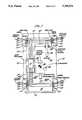
- FIG. 1is a schematic plan representation of a motor vehicle having a control system according to the invention
- FIG. 2is a schematic elevational view of one corner of the vehicle of FIG. 1;
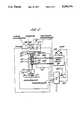
- FIG. 3is a block diagram showing the principles of operation of the control system of FIGS. 1 and 2.
- FIG. 1there is shown a motor vehicle 10 having four wheels 11, 12, 13, 14.
- the motor Vehicle 10has a body 15 and the wheels 11, 12, 13, 14 are connected to the body 15 by suspension and steering or drive components (not shown in detail).
- the suspension componentsare described below in relation to FIG. 2.
- the front wheels 11 and 12 of the vehicle 10are steerable, and the vehicle has a conventional steering linkage 17 driven by steering wheel 18 via steering column 19.
- the vehicle 10 of FIG. 1has an on-board computer 20 incorporating a microprocessor 21.
- Microprocessor 21receives signals from a number of sensors distributed about the vehicle and controls the suspension of the vehicle 10 in response to the signals.
- Each wheel and its associated hub assemblyhas three transducers capable of sending signals to microprocessor 21, these transducers being load cells 22, accelerometers 23 and displacement transducers.
- the load cells 22respectively measure the load acting between the top of each suspension strut 30 (best shown in FIG. 2) and the vehicle body 15.
- the accelerometers 23measure the respective vertical accelerations of the wheel/hub assemblies.
- the forces transmitted via the load cells 22 and calculated from the accelerometer measurementsare the dynamic forces acting on the vehicle body 15, and are occasioned, for example by the vehicle 10 encountering variations in the road surface along which it travels.
- the load cells 22, accelerometers 23 and microprocessor 21therefore constitute means for determining forces acting between the sprung mass (i.e. body 15) of the vehicle and one or more unsprung masses (i.e. the wheel/hub assemblies) and producing signals proportional to the forces.
- the load cells 22, accelerometers 23 and microprocessor 21also constitute means for resolving the dynamic force components.
- the microprocessor 21also receives signals from further transducers which signals are processed in the microprocessor 21 to represent steady state forces acting between the vehicle body 15 and each wheel/hub assembly.
- a gyrometer 24 located near the vehicle center of gravity indicated by reference numeral 26measures the yaw rate (i.e. rotational velocity) of the vehicle 10. Signals are generated by the gyrometer 24 when, for example, the vehicle follows a curved path.
- a longitudinal accelerometer 27indicates, for example, the extent to which the vehicle is accelerating and braking.
- a lateral accelerometer 28measures the vehicle lateral acceleration.
- the lateral accelerometeris also adjacent the vehicle center of gravity 26 and indicates, for example, the lateral acceleration effects of the vehicle travelling around a curve, and of the lateral component of gravitational acceleration when the vehicle 10 is on a cambered road.
- a steering angle sensor 29 located in the embodiment of FIG. 1 on the steering column 19measures the angle ⁇ through which the steering wheel is turned.
- the steering angle sensorcould be located in one of a variety of positions, for instance a suitable transducer could be included in the steering linkage 17 or on one of the front wheel/hub assemblies.
- the transducers 24, 27, 28 and 29 in combination with microprocessor 21constitute further means for determining forces acting between the sprung mass (i.e. the vehicle body 15) of the vehicle 10 and one or more unsprung masses (i.e. the wheel/hub assemblies) and producing signals proportional to the forces; and also constitute means for resolving the steady state components of the forces.
- the steady state forces acting between the vehicle body 15 and the wheel/hub assembliesare therefore those occasioned by the condition of the vehicle as determined by the driver thereof, for example whether the vehicle is decelerating being one such condition.
- the microprocessor 21is capable of determining, from the steady state force values, vector quantities in the form of velocities required between the sprung mass (i.e. the vehicle body 15) and the unsprung masses (i.e. the wheel/hub assemblies) to maintain a constant orientation of the vehicle body relative to a predetermined reference plane.
- the microprocessor 21is also capable of determining from the dynamic force values the values of vector quantities in the form of velocities required between the body 15 and the wheel/hub assemblies to eliminate the transmission of dynamic forces therebetween.
- the required velocitiesare transmitted as electrical signals to the wheel/hub assemblies via output lines 31 where actuators 32 incorporated within the suspension struts operate to apply the required velocities between each wheel/hub assembly and the vehicle body 15.
- FIG. 2shows schematically the arrangement of components forming the suspension strut associated with one corner of the vehicle 10. Also shown in FIG. 2 is the arrangement of the pump 33 and hydraulic supply circuit for the actuator 32 shown therein. Clearly, the circuit shown in FIG. 2 represents one quarter of the circuitry for the entire vehicle 10, and whilst the pump 33, hydraulic control circuit 32 and microprocessor 21 are common to all four suspension assemblies of the vehicle, the electrical control lines between the suspension assembly and the microprocessor 21; the hydraulic supply and return lines 36 and 37; and the suspension strut 30 are reproduced for the three suspension assemblies not shown in FIG. 2.
- the sprung mass of the vehicle in the form of the vehicle body 15is shown supported on a suspension strut indicated generally by the reference sign 30, which are in turn supported on a wheel and tire modelled as an unsprung mass 35 in the form of the wheel/hub assembly supported on a spring 36 and damper 37 representing the tire.
- the suspension components 30comprise means for applying vector quantities in the form of velocities to control the attitude of the vehicle, in the form of an hydraulic actuator 32, shown vertically aligned and secured at its upper end to a load cell 22 which is separated from the vehicle body 15 by an isolator 38, which may be, for example, a rubber block.
- the actuator 32need not necessarily be vertically alinged, depending on the space available for suspension components and the suspension layout adopted.
- the load cell 22is capable of measuring at least a portion of the loads acting between the wheel/hub assembly and the vehicle body and producing signals proportional to the loads.
- a spring 39is shown connected in parallel with the hydraulic actuator 32.
- the spring 39does not control the attitude of the vehicle in the way that it would in a vehicle having a conventional suspension system.
- Spring 39serves merely to reduce the power consumption of the control system of the invention by bearing a significant proportion of the static load of the vehicle body 15.
- actuator 32may take place over a wide range of displacements actually to effect control of the vehicle without requiring an excessive power consumption as would normally be required if the actuator were to support the static load of the vehicle body 15 in addition to controlling the steady state and dynamic loadings resulting from dynamic and steady state forces acting on the vehicle.
- the actuator 32is preferably a double-acting electro-hydraulic actuator comprising a sealed cylinder, a piston attached to a connecting rod and a flow control valve.
- the sealed cylinderis capable of containing high pressure fluids without significant leakage.
- the pistonis attached to a connecting rod and is housed within the cylinder.
- the piston deviceis cylindered in to two chambers.
- the pistonis fitted with seals to prevent significant leakage from one chamber to another.
- the hydraulic circuit 34preferably comprises a four port control valve, or electro-hydraulic servo valve (EHSV), which has two input and two output ports. One input port is connected to a source of high pressure hydraulic fluid, the other input port is connected to a return path which is held at low pressure.
- EHSVelectro-hydraulic servo valve
- the EHSVis designed such that when an electric current is passed through its energising coil, hydraulic fluid is allowed to flow from the high pressure source in to one cylinder chamber of the actuator 32, whilst fluid is allowed to flow from the other chamber of the actuator 32 in to the return path. This causes the piston to move relative to the cylinder with a velocity proportional to the electric current applied to the energising coil and the load reacted by the differential pressure across the piston. When the plurality of the current is reversed the velocity of the piston is reversed. If the EHSV conforms to the ideal, then the velocity of the piston will be zero when the electrical current applied to the energising coil is zero.
- spring 39Since the power consumption of actuator 32 is reduced, by the use of spring 39, its piston area may be designed to be relatively small, thereby producing a compact device. Further, spring 39 serves as a fail-safe device in that it supports the static load of the vehicle body 15 in the event of total failure of the control system of the invention.
- the input and output ports of the hydraulic actuator 32are connected via hydraulic pipework 32a and 32b to a hydraulic control circuit 34 including a suitable supply pump 33.
- the hydraulic circuit 34operates, via electrical connection 34', under the command of microprocessor 21 which produces a demanded output of the actuator 32 in response to the number of measured inputs.
- the suspension strut 30 and hydraulic circuit 34therefore constitute means for applying required vector quantities between the vehicle body 15 and the wheel/hub assembly in the form of unsprung mass 35.
- FIG. 3there is shown a schematic block diagram of the manner in which the microprocessor 21 conditions the various signals to produce the output signals transmitted via line 34'.
- a chain linedivides the diagram into three portions.
- Portion Aoccurring generally above the chain line, represents those steps concerned with dynamic forces acting on the vehicle;
- portion Boccurring generally below the chain line represents processing steps concerned with steady state forces acting on the vehicle;
- portion Crepresents the final output of the microprocessor, this being a combination of the output of portions A and B.
- the signals from the four load cells 22 and hub accelerometers 23are fed into block 42 which reconfigures the dynamic force values represented by the signals as modal forces acting on the vehicle body, the modes corresponding to the four rigid body modes of displacement, i.e. the heave, pitch, roll and warp modes.
- the forcesare calculated as being forces at the ⁇ tire patch ⁇ , that is to say the point of contact of the tire with the road. These forces are calculated as being the sum of the measured forces and the product of the masses of the unsprung masses with their respective accelerations. This sum is necessary since force in a tire at the tire patch will not all be transmitted to the body of the vehicle; a portion will accelerate the wheel and hub assembly to which the tire is attached.
- Block 43unmeasured modal forces are added to the measured modal forces calculated in Block 42.
- the applicantenvisages a situation wherein springs are used in parallel with the actuators in the vehicle suspension and only the force transmitted by the actuators to the body is measured.
- the force transmitted to the body by the springscan be calculated from measured displacements of the actuator, which are fed to the box 42 from the LVITs 41.
- the modal loadsmay also be adjusted to compensate for unmeasured loads, transmitted to the vehicle body by the suspension linkages and also components of horizontal load on the wheels transmitted through the actuator by reason of imperfection suspension arrangements.
- the Block 44removes from the modal forces calculated those forces due to the steady state inputs to the vehicle, which are calculated in Portion B, discussed below.
- the corrected modal vectorcan be written: ##EQU1## ⁇ Fcm ⁇ is the vector of corrected modal forces ⁇ Fr ⁇ is the vector of measured loads
- ⁇ DDXu ⁇is the vector of measured unsprung mass accelerations
- ⁇ e ⁇is the transpose of the vector (nx+, nx-, ny, Dr)
- nxlongitudinal acceleration
- nyis lateral acceleration
- Dris yaw acceleration
- ⁇ Xdm ⁇is the vector of modal actuator displacements
- ⁇ Xx ⁇is the position offset vector
- ⁇ Kt ⁇is a diagonal matrix of tire/isolator stiffness
- ⁇ Mm ⁇is a diagonal matrix proportional to hub/wheel masses
- ⁇ Tfm ⁇is the load modal transformation matrix
- Tinin a matrix of constant coefficients for transforming the measured ( ⁇ e) signals to steady state modal force signals.
- Tspis a matrix of the stiffness of springs connected in parallel with actuators of the system.
- the block 46synthesis spring and damper units and calculates modal velocity demands.
- the modal velocity demandsare then turned into individual actuator co-ordinates.
- the signals from accelerometers 23are, in addition, processed in block 45 as individual hub velocity demands which are fed forwardly to block 46 for combination with the calculated corner velocity demands.
- the suspension simulationis further enhanced by the adding of the weighted unsprung mass inertial velocity to each actuator demand. This provides the potential for introducing inertial damping of the unsprung mass.
- the output of block 46is filtered in high pass filter block 47. This is necessary to ensure that measurement bias errors do not corrupt the simulation.
- Block 48represents an electronic bump stop control which may optionally modify the output of portion A of the program.
- the electronic bump stop controlis disclosed in a co-pending patent application Ser. No. 07/777,215 of the applicants.
- the output signals representing the steady state forces, from the LVIT 41, gyrometer 24, longitudinal accelerometer 27, lateral accelerometer 28, a vehicle speed sensor 25 and the steering angle sensor 29are conditioned in corresponding blocks 41a, 24a, 27a, 28a, 25a and 29a to ensure conformity of signal types (i.e. to resolve the measured steady state variables into modal force values).
- the block 53 of the control systemmodels a series of actuators, controlling the suspension of the vehicle.
- the steady state forcesare converted in to required corner displacements, which are output to the control system 50 which in turn directly controls the actual actuators of the vehicle.
- Portion Binstructs the actuators to extend and contract to improve the vehicle ride and handling.
- portion BThe additional motion of the actuators demanded by portion B could alter measured loads, which would, in turn, cause an unwanted reaction from the simulated suspension in portion A.
- the changes in measured loads to be expected from such additional actuator motionare estimated and subtracted from the measured loads in order to eliminate the unwanted reaction from the simulated suspension of portion A.
- portion Bacts to control the average position of the actuators in order to improve the ride of the vehicle.
- portion Bconsiders the four actuators connected in series to the four actuators controlled by portion A. Displacement of the theoretical actuators controlled by portion B will therefore alter the average displacement position of the combination of the two actuators. In practice, portion B of the control system varies the average position of the actual actuators used by the vehicle.
- Portion B of the control systemoutputs a required displacement demand, whilst portion A of the control system outputs a required velocity demand. Therefore, it is necessary that one of the outputs is converted in the block 50, so that the outputs can be combined and used to control the actuators of the vehicle.
- the present inventionprovides an active suspension control system which both controls the actuators so that road inputs are not transmitted to the vehicle and also controls the actuators so that the average displacement of each actuator can be varied to provide a better vehicle ride and performance.
- a vehicle bodycan be prevented to a large extent from rolling as the vehicle corners.
- the portion B of the control system of the inventionacts to prevent the actuators on the side of the car on the outside of a corner from deflecting in response to the roll forces on the vehicle caused by its cornering. In fact, to compensate for any flexibility in the suspension system the actuators can be extended on roll.
- the microprocessorsplits the input signals from the sensors according to whether they represent dynamic (i.e. generally relatively high frequency) force inputs or steady state (i.e. generally relatively low frequency) force inputs, the processing of the signals can be achieved rapidly to produce combined output signals. This permits the control system of the invention to sample data at a fast rate comparable with the rate of change of the various signal values characteristic of vehicle active suspension systems, thereby permitting accurate control of the vehicle suspension system.
- portion A of the control systemsamples at a higher rate than portion B, this being advantageous in that the number of calculations required by the control system for a fixed time period is decreased.
- the sampling rate for portion Amust be reasonably high since the said inputs will be of high frequency.
- sampling rate of portion Bneed not be so high since the frequencies of the steady state signals are generally far smaller.
Landscapes
- Engineering & Computer Science (AREA)
- Mechanical Engineering (AREA)
- Vehicle Body Suspensions (AREA)
Abstract
Description
Claims (12)
Applications Claiming Priority (3)
| Application Number | Priority Date | Filing Date | Title |
|---|---|---|---|
| GB898910392AGB8910392D0 (en) | 1989-05-05 | 1989-05-05 | A vehicle suspension control system |
| GB8910392 | 1989-05-05 | ||
| PCT/GB1990/000690WO1990013448A1 (en) | 1989-05-05 | 1990-05-04 | A vehicle suspension control system |
Publications (1)
| Publication Number | Publication Date |
|---|---|
| US5295074Atrue US5295074A (en) | 1994-03-15 |
Family
ID=10656298
Family Applications (1)
| Application Number | Title | Priority Date | Filing Date |
|---|---|---|---|
| US07/777,231Expired - LifetimeUS5295074A (en) | 1989-05-05 | 1990-05-04 | Vehicle suspension control system |
Country Status (8)
| Country | Link |
|---|---|
| US (1) | US5295074A (en) |
| EP (1) | EP0470991B1 (en) |
| JP (1) | JP2997044B2 (en) |
| CA (1) | CA2054206A1 (en) |
| DE (1) | DE69010681T2 (en) |
| ES (1) | ES2061035T3 (en) |
| GB (1) | GB8910392D0 (en) |
| WO (1) | WO1990013448A1 (en) |
Cited By (41)
| Publication number | Priority date | Publication date | Assignee | Title |
|---|---|---|---|---|
| US5440488A (en)* | 1992-09-16 | 1995-08-08 | Unisia Jecs Corporation | System for controlling damping force characteristic of shock absorber of vehicle |
| US5475596A (en)* | 1991-05-20 | 1995-12-12 | General Motors Corporation | Full car semi-active suspension control based on quarter car control |
| WO1996005975A1 (en)* | 1994-08-18 | 1996-02-29 | Aimrite Systems International, Inc. | Computer optimized adaptive suspension system and method improvements |
| US5510986A (en)* | 1994-03-14 | 1996-04-23 | Trw Inc. | Method and apparatus for controlling an active suspension system |
| US5706196A (en)* | 1993-06-07 | 1998-01-06 | Monroe Auto Equipment Co. | Method and apparatus for determining the velocity of a vehicle body |
| US5726877A (en)* | 1993-12-09 | 1998-03-10 | Mannesmann Rexroth Gmbh | Method for the adaptive adjustment of the control parameters of an electro-hydraulic axis of motion |
| US5899288A (en)* | 1997-11-12 | 1999-05-04 | Case Corporation | Active suspension system for a work vehicle |
| US5941920A (en)* | 1997-11-12 | 1999-08-24 | Case Corporation | Control of an active suspension system for a work vehicle based upon a parameter of another vehicle system |
| US6000702A (en)* | 1996-04-20 | 1999-12-14 | Daimlerchrysler Ag | Active vehicle suspension system |
| US6000703A (en)* | 1997-11-12 | 1999-12-14 | Case Corporation | Active suspension system for a work vehicle having adjustable performance parameters |
| US6029764A (en)* | 1997-11-12 | 2000-02-29 | Case Corporation | Coordinated control of an active suspension system for a work vehicle |
| US6149190A (en)* | 1993-05-26 | 2000-11-21 | Kionix, Inc. | Micromechanical accelerometer for automotive applications |
| US6169939B1 (en) | 1998-09-08 | 2001-01-02 | Ford Global Technologies, Inc. | Method of generating a vehicle lateral acceleration signal for use in an active tilt control system |
| US6170332B1 (en) | 1993-05-26 | 2001-01-09 | Cornell Research Foundation, Inc. | Micromechanical accelerometer for automotive applications |
| US20030001346A1 (en)* | 1998-11-11 | 2003-01-02 | Hamilton James M. | Enhanced computer optimized adaptive suspension system and method |
| US6591677B2 (en)* | 2001-01-29 | 2003-07-15 | Ford Global Technologies, Llc | System and method for detecting vehicle mechanical loading |
| US20040111707A1 (en)* | 2000-12-15 | 2004-06-10 | Bliss Andrew L. | Debugger for multiple processors and multiple debugging types |
| US6898501B2 (en) | 1999-07-15 | 2005-05-24 | Cnh America Llc | Apparatus for facilitating reduction of vibration in a work vehicle having an active CAB suspension system |
| US20050146098A1 (en)* | 2002-05-31 | 2005-07-07 | Green Steve J. | Integrated control unit for an active roll control system for a vehicle suspension system |
| EP1552970A1 (en)* | 2004-01-07 | 2005-07-13 | Delphi Technologies, Inc. | Adjustable force suspension |
| US20200114997A1 (en)* | 2018-10-10 | 2020-04-16 | Trioliet B.V. | Agricultural transport vehicle with weighing system |
| US11162555B2 (en) | 2008-08-25 | 2021-11-02 | Fox Factory, Inc. | Methods and apparatus for suspension lock out and signal generation |
| US11168758B2 (en) | 2009-01-07 | 2021-11-09 | Fox Factory, Inc. | Method and apparatus for an adjustable damper |
| US11173765B2 (en) | 2009-01-07 | 2021-11-16 | Fox Factory, Inc. | Method and apparatus for an adjustable damper |
| US11279198B2 (en) | 2009-10-13 | 2022-03-22 | Fox Factory, Inc. | Methods and apparatus for controlling a fluid damper |
| US11299233B2 (en) | 2009-01-07 | 2022-04-12 | Fox Factory, Inc. | Method and apparatus for an adjustable damper |
| US11306798B2 (en) | 2008-05-09 | 2022-04-19 | Fox Factory, Inc. | Position sensitive suspension damping with an active valve |
| US11408482B2 (en) | 2009-01-07 | 2022-08-09 | Fox Factory, Inc. | Bypass for a suspension damper |
| US11472252B2 (en) | 2016-04-08 | 2022-10-18 | Fox Factory, Inc. | Electronic compression and rebound control |
| US11499601B2 (en) | 2009-01-07 | 2022-11-15 | Fox Factory, Inc. | Remotely operated bypass for a suspension damper |
| US11519477B2 (en) | 2009-01-07 | 2022-12-06 | Fox Factory, Inc. | Compression isolator for a suspension damper |
| US11549565B2 (en)* | 2009-01-07 | 2023-01-10 | Fox Factory, Inc. | Method and apparatus for an adjustable damper |
| US11619278B2 (en) | 2009-03-19 | 2023-04-04 | Fox Factory, Inc. | Methods and apparatus for suspension adjustment |
| US11629774B2 (en) | 2012-05-10 | 2023-04-18 | Fox Factory, Inc. | Method and apparatus for an adjustable damper |
| US11708878B2 (en) | 2010-01-20 | 2023-07-25 | Fox Factory, Inc. | Remotely operated bypass for a suspension damper |
| US11760150B2 (en) | 2012-01-25 | 2023-09-19 | Fox Factory, Inc. | Suspension damper with by-pass valves |
| US11796028B2 (en) | 2011-05-31 | 2023-10-24 | Fox Factory, Inc. | Methods and apparatus for position sensitive suspension damping |
| US11897571B2 (en) | 2008-11-25 | 2024-02-13 | Fox Factory, Inc. | Seat post |
| US11958328B2 (en) | 2011-09-12 | 2024-04-16 | Fox Factory, Inc. | Methods and apparatus for suspension set up |
| US12103349B2 (en) | 2009-03-19 | 2024-10-01 | Fox Factory, Inc. | Methods and apparatus for selective spring pre-load adjustment |
| US12122205B2 (en) | 2009-01-07 | 2024-10-22 | Fox Factory, Inc. | Active valve for an internal bypass |
Families Citing this family (9)
| Publication number | Priority date | Publication date | Assignee | Title |
|---|---|---|---|---|
| US5097419A (en)* | 1990-06-08 | 1992-03-17 | Monroe Auto Equipment Company | Method and apparatus for dynamic leveling |
| DE4119414A1 (en)* | 1991-06-13 | 1992-12-17 | Bosch Gmbh Robert | AGRICULTURAL USE OF TRACTOR WITH A LINKED LIFT |
| GB9214543D0 (en)* | 1992-07-08 | 1992-08-19 | Lotus Car | A vehicle suspension control system |
| FR2704511A1 (en)* | 1993-04-30 | 1994-11-04 | Vaux Eric | Vehicle of the type comprising a support module and a cabin module and a controlled device for connecting the two modules together |
| DE10318110A1 (en)* | 2003-04-22 | 2004-11-11 | Continental Aktiengesellschaft | Method of controlling damping |
| DE102006044627A1 (en) | 2006-09-19 | 2008-03-27 | Ricardo Deutschland Gmbh | Active suspension system |
| EP2156970A1 (en) | 2008-08-12 | 2010-02-24 | Nederlandse Organisatie voor toegepast- natuurwetenschappelijk onderzoek TNO | Multi-point hydraulic suspension system for a land vehicle |
| DE102009060999A1 (en) | 2009-06-24 | 2011-01-05 | German Gresser | Energy-optimized electric vehicle with autonomous power supply and method for power generation, preferably from kinetic and gravitational energy |
| US8376373B2 (en)* | 2009-11-23 | 2013-02-19 | General Dynamics Land Systems | Controllable suspension architecture for enhanced armoured vehicle survivability |
Citations (11)
| Publication number | Priority date | Publication date | Assignee | Title |
|---|---|---|---|---|
| EP0114757A1 (en)* | 1983-01-21 | 1984-08-01 | Group Lotus Plc | Vehicle suspension system |
| JPS6050013A (en)* | 1983-08-31 | 1985-03-19 | Nissan Motor Co Ltd | Driving condition detecting device |
| EP0151421A2 (en)* | 1984-01-20 | 1985-08-14 | Nissan Motor Co., Ltd. | Automotive suspension control system with road-condition-dependent damping characteristics |
| JPS62221906A (en)* | 1986-03-25 | 1987-09-30 | Nissan Motor Co Ltd | Suspension control device for vehicle |
| EP0249227A2 (en)* | 1986-06-12 | 1987-12-16 | Nissan Motor Co., Ltd. | Actively controlled automotive suspension system with mutually independent hydraulic systems having mutually different damping characteristics for improving response characteristics in active suspension control |
| US4761022A (en)* | 1986-03-08 | 1988-08-02 | Toyota Jidosha Kabushiki Kaisha | Suspension controller for improved turning |
| US4898257A (en)* | 1988-09-30 | 1990-02-06 | Brandstadter Jack M | Active hydropneumatic suspension system |
| US4907154A (en)* | 1986-10-31 | 1990-03-06 | Kabushiki Kaisha Toyota Chuo Kenkyusho | Vibration control apparatus |
| US5046008A (en)* | 1988-06-27 | 1991-09-03 | Bayerische Motoren Werke Ag | Control device for stabilizing the rolling motion of a vehicle |
| US5071157A (en)* | 1989-11-02 | 1991-12-10 | General Motors Corporation | Full vehicle suspension control |
| US5119297A (en)* | 1989-03-04 | 1992-06-02 | Toyota Jidosha Kabushiki Kaisha | Hydraulic active suspension system for a vehicle capable of enhancing both the comfortability and the controllability of the attitude of vehicle body |
- 1989
- 1989-05-05GBGB898910392Apatent/GB8910392D0/enactivePending
- 1990
- 1990-05-04DEDE69010681Tpatent/DE69010681T2/ennot_activeExpired - Fee Related
- 1990-05-04EPEP90907205Apatent/EP0470991B1/ennot_activeExpired - Lifetime
- 1990-05-04JPJP2506685Apatent/JP2997044B2/ennot_activeExpired - Fee Related
- 1990-05-04ESES90907205Tpatent/ES2061035T3/ennot_activeExpired - Lifetime
- 1990-05-04USUS07/777,231patent/US5295074A/ennot_activeExpired - Lifetime
- 1990-05-04CACA002054206Apatent/CA2054206A1/ennot_activeAbandoned
- 1990-05-04WOPCT/GB1990/000690patent/WO1990013448A1/enactiveIP Right Grant
Patent Citations (12)
| Publication number | Priority date | Publication date | Assignee | Title |
|---|---|---|---|---|
| EP0114757A1 (en)* | 1983-01-21 | 1984-08-01 | Group Lotus Plc | Vehicle suspension system |
| JPS6050013A (en)* | 1983-08-31 | 1985-03-19 | Nissan Motor Co Ltd | Driving condition detecting device |
| EP0151421A2 (en)* | 1984-01-20 | 1985-08-14 | Nissan Motor Co., Ltd. | Automotive suspension control system with road-condition-dependent damping characteristics |
| US4967359A (en)* | 1984-01-20 | 1990-10-30 | Nissan Motor Co., Ltd. | Automotive suspension control system with road-condition-dependent damping characteristics |
| US4761022A (en)* | 1986-03-08 | 1988-08-02 | Toyota Jidosha Kabushiki Kaisha | Suspension controller for improved turning |
| JPS62221906A (en)* | 1986-03-25 | 1987-09-30 | Nissan Motor Co Ltd | Suspension control device for vehicle |
| EP0249227A2 (en)* | 1986-06-12 | 1987-12-16 | Nissan Motor Co., Ltd. | Actively controlled automotive suspension system with mutually independent hydraulic systems having mutually different damping characteristics for improving response characteristics in active suspension control |
| US4907154A (en)* | 1986-10-31 | 1990-03-06 | Kabushiki Kaisha Toyota Chuo Kenkyusho | Vibration control apparatus |
| US5046008A (en)* | 1988-06-27 | 1991-09-03 | Bayerische Motoren Werke Ag | Control device for stabilizing the rolling motion of a vehicle |
| US4898257A (en)* | 1988-09-30 | 1990-02-06 | Brandstadter Jack M | Active hydropneumatic suspension system |
| US5119297A (en)* | 1989-03-04 | 1992-06-02 | Toyota Jidosha Kabushiki Kaisha | Hydraulic active suspension system for a vehicle capable of enhancing both the comfortability and the controllability of the attitude of vehicle body |
| US5071157A (en)* | 1989-11-02 | 1991-12-10 | General Motors Corporation | Full vehicle suspension control |
Cited By (62)
| Publication number | Priority date | Publication date | Assignee | Title |
|---|---|---|---|---|
| US5475596A (en)* | 1991-05-20 | 1995-12-12 | General Motors Corporation | Full car semi-active suspension control based on quarter car control |
| US5440488A (en)* | 1992-09-16 | 1995-08-08 | Unisia Jecs Corporation | System for controlling damping force characteristic of shock absorber of vehicle |
| US6149190A (en)* | 1993-05-26 | 2000-11-21 | Kionix, Inc. | Micromechanical accelerometer for automotive applications |
| US6199874B1 (en) | 1993-05-26 | 2001-03-13 | Cornell Research Foundation Inc. | Microelectromechanical accelerometer for automotive applications |
| US6170332B1 (en) | 1993-05-26 | 2001-01-09 | Cornell Research Foundation, Inc. | Micromechanical accelerometer for automotive applications |
| US5706196A (en)* | 1993-06-07 | 1998-01-06 | Monroe Auto Equipment Co. | Method and apparatus for determining the velocity of a vehicle body |
| US5726877A (en)* | 1993-12-09 | 1998-03-10 | Mannesmann Rexroth Gmbh | Method for the adaptive adjustment of the control parameters of an electro-hydraulic axis of motion |
| US5510986A (en)* | 1994-03-14 | 1996-04-23 | Trw Inc. | Method and apparatus for controlling an active suspension system |
| WO1996005975A1 (en)* | 1994-08-18 | 1996-02-29 | Aimrite Systems International, Inc. | Computer optimized adaptive suspension system and method improvements |
| US6000702A (en)* | 1996-04-20 | 1999-12-14 | Daimlerchrysler Ag | Active vehicle suspension system |
| US5941920A (en)* | 1997-11-12 | 1999-08-24 | Case Corporation | Control of an active suspension system for a work vehicle based upon a parameter of another vehicle system |
| US6029764A (en)* | 1997-11-12 | 2000-02-29 | Case Corporation | Coordinated control of an active suspension system for a work vehicle |
| US6000703A (en)* | 1997-11-12 | 1999-12-14 | Case Corporation | Active suspension system for a work vehicle having adjustable performance parameters |
| US5899288A (en)* | 1997-11-12 | 1999-05-04 | Case Corporation | Active suspension system for a work vehicle |
| US6169939B1 (en) | 1998-09-08 | 2001-01-02 | Ford Global Technologies, Inc. | Method of generating a vehicle lateral acceleration signal for use in an active tilt control system |
| US20050098401A1 (en)* | 1998-11-11 | 2005-05-12 | Hamilton James M. | Enhanced computer optimized adaptive suspension system and method |
| US6502837B1 (en) | 1998-11-11 | 2003-01-07 | Kenmar Company Trust | Enhanced computer optimized adaptive suspension system and method |
| US20030001346A1 (en)* | 1998-11-11 | 2003-01-02 | Hamilton James M. | Enhanced computer optimized adaptive suspension system and method |
| US7076351B2 (en) | 1998-11-11 | 2006-07-11 | Great Northern Technologies, Llc | Enhanced computer optimized adaptive suspension system and method |
| US6898501B2 (en) | 1999-07-15 | 2005-05-24 | Cnh America Llc | Apparatus for facilitating reduction of vibration in a work vehicle having an active CAB suspension system |
| US20040111707A1 (en)* | 2000-12-15 | 2004-06-10 | Bliss Andrew L. | Debugger for multiple processors and multiple debugging types |
| US6591677B2 (en)* | 2001-01-29 | 2003-07-15 | Ford Global Technologies, Llc | System and method for detecting vehicle mechanical loading |
| US20050146098A1 (en)* | 2002-05-31 | 2005-07-07 | Green Steve J. | Integrated control unit for an active roll control system for a vehicle suspension system |
| US7234707B2 (en) | 2002-05-31 | 2007-06-26 | Kelsey-Hayes Company | Integrated control unit for an active roll control system for a vehicle suspension system |
| EP1552970A1 (en)* | 2004-01-07 | 2005-07-13 | Delphi Technologies, Inc. | Adjustable force suspension |
| US11306798B2 (en) | 2008-05-09 | 2022-04-19 | Fox Factory, Inc. | Position sensitive suspension damping with an active valve |
| US11162555B2 (en) | 2008-08-25 | 2021-11-02 | Fox Factory, Inc. | Methods and apparatus for suspension lock out and signal generation |
| US11897571B2 (en) | 2008-11-25 | 2024-02-13 | Fox Factory, Inc. | Seat post |
| US11299233B2 (en) | 2009-01-07 | 2022-04-12 | Fox Factory, Inc. | Method and apparatus for an adjustable damper |
| US12044286B2 (en) | 2009-01-07 | 2024-07-23 | Fox Factory, Inc. | Compression isolator for a suspension damper |
| US11173765B2 (en) | 2009-01-07 | 2021-11-16 | Fox Factory, Inc. | Method and apparatus for an adjustable damper |
| US11168758B2 (en) | 2009-01-07 | 2021-11-09 | Fox Factory, Inc. | Method and apparatus for an adjustable damper |
| US11408482B2 (en) | 2009-01-07 | 2022-08-09 | Fox Factory, Inc. | Bypass for a suspension damper |
| US12377699B2 (en) | 2009-01-07 | 2025-08-05 | Fox Factory, Inc. | Method and apparatus for an adjustable damper |
| US11499601B2 (en) | 2009-01-07 | 2022-11-15 | Fox Factory, Inc. | Remotely operated bypass for a suspension damper |
| US11519477B2 (en) | 2009-01-07 | 2022-12-06 | Fox Factory, Inc. | Compression isolator for a suspension damper |
| US11549565B2 (en)* | 2009-01-07 | 2023-01-10 | Fox Factory, Inc. | Method and apparatus for an adjustable damper |
| US12371122B2 (en) | 2009-01-07 | 2025-07-29 | Fox Factory, Inc. | Method and apparatus for an adjustable damper |
| US12257871B2 (en) | 2009-01-07 | 2025-03-25 | Fox Factory, Inc. | Method and apparatus for an adjustable damper |
| US11660924B2 (en) | 2009-01-07 | 2023-05-30 | Fox Factory, Inc. | Method and apparatus for an adjustable damper |
| US12134293B2 (en) | 2009-01-07 | 2024-11-05 | Fox Factory, Inc. | Method and apparatus for an adjustable damper |
| US12122205B2 (en) | 2009-01-07 | 2024-10-22 | Fox Factory, Inc. | Active valve for an internal bypass |
| US12091122B2 (en) | 2009-01-07 | 2024-09-17 | Fox Factory, Inc. | Method and apparatus for an adjustable damper |
| US11794543B2 (en) | 2009-01-07 | 2023-10-24 | Fox Factory, Inc. | Method and apparatus for an adjustable damper |
| US11976706B2 (en) | 2009-01-07 | 2024-05-07 | Fox Factory, Inc. | Remotely operated bypass for a suspension damper |
| US11866120B2 (en) | 2009-01-07 | 2024-01-09 | Fox Factory, Inc. | Method and apparatus for an adjustable damper |
| US11890908B2 (en) | 2009-01-07 | 2024-02-06 | Fox Factory, Inc. | Method and apparatus for an adjustable damper |
| US11920655B2 (en) | 2009-03-19 | 2024-03-05 | Fox Factory, Inc. | Methods and apparatus for suspension adjustment |
| US11619278B2 (en) | 2009-03-19 | 2023-04-04 | Fox Factory, Inc. | Methods and apparatus for suspension adjustment |
| US12163569B2 (en) | 2009-03-19 | 2024-12-10 | Fox Factory, Inc. | Methods and apparatus for suspension adjustment |
| US12103349B2 (en) | 2009-03-19 | 2024-10-01 | Fox Factory, Inc. | Methods and apparatus for selective spring pre-load adjustment |
| US11279198B2 (en) | 2009-10-13 | 2022-03-22 | Fox Factory, Inc. | Methods and apparatus for controlling a fluid damper |
| US12005755B2 (en) | 2009-10-13 | 2024-06-11 | Fox Factory, Inc. | Methods and apparatus for controlling a fluid damper |
| US11708878B2 (en) | 2010-01-20 | 2023-07-25 | Fox Factory, Inc. | Remotely operated bypass for a suspension damper |
| US11796028B2 (en) | 2011-05-31 | 2023-10-24 | Fox Factory, Inc. | Methods and apparatus for position sensitive suspension damping |
| US11958328B2 (en) | 2011-09-12 | 2024-04-16 | Fox Factory, Inc. | Methods and apparatus for suspension set up |
| US11760150B2 (en) | 2012-01-25 | 2023-09-19 | Fox Factory, Inc. | Suspension damper with by-pass valves |
| US12038062B2 (en) | 2012-05-10 | 2024-07-16 | Fox Factory, Inc. | Method and apparatus for an adjustable damper |
| US11629774B2 (en) | 2012-05-10 | 2023-04-18 | Fox Factory, Inc. | Method and apparatus for an adjustable damper |
| US11472252B2 (en) | 2016-04-08 | 2022-10-18 | Fox Factory, Inc. | Electronic compression and rebound control |
| US20200114997A1 (en)* | 2018-10-10 | 2020-04-16 | Trioliet B.V. | Agricultural transport vehicle with weighing system |
| US11691684B2 (en)* | 2018-10-10 | 2023-07-04 | Trioliet B.V. | Agricultural transport vehicle with weighing system |
Also Published As
| Publication number | Publication date |
|---|---|
| EP0470991A1 (en) | 1992-02-19 |
| JPH04505141A (en) | 1992-09-10 |
| DE69010681D1 (en) | 1994-08-18 |
| DE69010681T2 (en) | 1995-02-23 |
| CA2054206A1 (en) | 1990-11-06 |
| GB8910392D0 (en) | 1989-06-21 |
| ES2061035T3 (en) | 1994-12-01 |
| WO1990013448A1 (en) | 1990-11-15 |
| JP2997044B2 (en) | 2000-01-11 |
| EP0470991B1 (en) | 1994-07-13 |
Similar Documents
| Publication | Publication Date | Title |
|---|---|---|
| US5295074A (en) | Vehicle suspension control system | |
| US5217246A (en) | Control system for controlling the suspension of a land vehicle | |
| US5475593A (en) | Distributed active vehicle suspension system | |
| US4625993A (en) | Vehicle suspension system | |
| US5510986A (en) | Method and apparatus for controlling an active suspension system | |
| US5297045A (en) | Vehicle suspension system | |
| US5291406A (en) | Land vehicle suspension control system | |
| JP3446959B2 (en) | Signal generation system for open-loop or closed-loop control of a petri dish capable of open-loop or closed-loop control of a motion sequence | |
| US5590898A (en) | Vehicle suspension system | |
| US5137299A (en) | Active suspension system | |
| US5289379A (en) | Land vehicle suspension control system | |
| Yokoya et al. | Integrated control system between active control suspension and four wheel steering for the 1989 Celica | |
| US5563789A (en) | System to generate signals for control or regulation of a controllable or regulable chassis | |
| Darling et al. | A theoretical investigation of a prototype active roll control system | |
| Milliken | Active suspension | |
| GB2271535A (en) | A vehicle suspension system | |
| JPS6328709A (en) | Stabilizer device | |
| Villegas et al. | State-of-the-art of integrated chassis control. deliverable 2 |
Legal Events
| Date | Code | Title | Description |
|---|---|---|---|
| AS | Assignment | Owner name:GROUP LOTUS PLC Free format text:ASSIGNMENT OF ASSIGNORS INTEREST.;ASSIGNOR:WILLIAMS, DAVID A.;REEL/FRAME:005991/0616 Effective date:19911108 | |
| AS | Assignment | Owner name:ELF ATOCHEM S.A. Free format text:CHANGE OF NAME;ASSIGNOR:ATOCHEM;REEL/FRAME:006184/0235 Effective date:19920410 | |
| AS | Assignment | Owner name:GENERAL MOTORS CORPORATION, MICHIGAN Free format text:LICENSE;ASSIGNOR:GROUP LOTUS PLC AND LOTUS CARS LIMITED;REEL/FRAME:006726/0124 Effective date:19930825 | |
| STCF | Information on status: patent grant | Free format text:PATENTED CASE | |
| AS | Assignment | Owner name:GROUP LOTUS LIMITED, UNITED KINGDOM Free format text:CHANGE OF NAME;ASSIGNOR:GROUP LOTUS PLC;REEL/FRAME:006957/0171 Effective date:19931217 | |
| FPAY | Fee payment | Year of fee payment:4 | |
| FEPP | Fee payment procedure | Free format text:PAYOR NUMBER ASSIGNED (ORIGINAL EVENT CODE: ASPN); ENTITY STATUS OF PATENT OWNER: LARGE ENTITY | |
| FPAY | Fee payment | Year of fee payment:8 | |
| FPAY | Fee payment | Year of fee payment:12 |