US5294748A - Equipment cabinet - Google Patents
Equipment cabinetDownload PDFInfo
- Publication number
- US5294748A US5294748AUS07/931,474US93147492AUS5294748AUS 5294748 AUS5294748 AUS 5294748AUS 93147492 AUS93147492 AUS 93147492AUS 5294748 AUS5294748 AUS 5294748A
- Authority
- US
- United States
- Prior art keywords
- equipment cabinet
- strips
- casing components
- contact
- cabinet according
- Prior art date
- Legal status (The legal status is an assumption and is not a legal conclusion. Google has not performed a legal analysis and makes no representation as to the accuracy of the status listed.)
- Expired - Lifetime
Links
- 239000004020conductorSubstances0.000claimsabstractdescription5
- 230000005670electromagnetic radiationEffects0.000claimsabstractdescription5
- 239000002184metalSubstances0.000claimsdescription15
- 229910052751metalInorganic materials0.000claimsdescription15
- 238000007789sealingMethods0.000claimsdescription15
- 230000002093peripheral effectEffects0.000claimsdescription7
- 230000013011matingEffects0.000abstract1
- 229910000831SteelInorganic materials0.000description3
- 239000010959steelSubstances0.000description3
- PXHVJJICTQNCMI-UHFFFAOYSA-NNickelChemical compound[Ni]PXHVJJICTQNCMI-UHFFFAOYSA-N0.000description2
- 238000005260corrosionMethods0.000description2
- 230000007797corrosionEffects0.000description2
- 238000003466weldingMethods0.000description2
- 230000001154acute effectEffects0.000description1
- 230000006978adaptationEffects0.000description1
- 239000000853adhesiveSubstances0.000description1
- 238000004026adhesive bondingMethods0.000description1
- 230000001070adhesive effectEffects0.000description1
- 238000000576coating methodMethods0.000description1
- 238000007598dipping methodMethods0.000description1
- 239000000428dustSubstances0.000description1
- 238000009713electroplatingMethods0.000description1
- 238000003780insertionMethods0.000description1
- 230000037431insertionEffects0.000description1
- 239000004922lacquerSubstances0.000description1
- 239000007769metal materialSubstances0.000description1
- 238000000034methodMethods0.000description1
- 238000012986modificationMethods0.000description1
- 230000004048modificationEffects0.000description1
- 229910052759nickelInorganic materials0.000description1
- 230000001590oxidative effectEffects0.000description1
- 239000004033plasticSubstances0.000description1
- 238000000926separation methodMethods0.000description1
- 239000007921spraySubstances0.000description1
- 229910001220stainless steelInorganic materials0.000description1
- 239000010935stainless steelSubstances0.000description1
- 239000013589supplementSubstances0.000description1
- XLYOFNOQVPJJNP-UHFFFAOYSA-NwaterSubstancesOXLYOFNOQVPJJNP-UHFFFAOYSA-N0.000description1
Images
Classifications
- H—ELECTRICITY
- H05—ELECTRIC TECHNIQUES NOT OTHERWISE PROVIDED FOR
- H05K—PRINTED CIRCUITS; CASINGS OR CONSTRUCTIONAL DETAILS OF ELECTRIC APPARATUS; MANUFACTURE OF ASSEMBLAGES OF ELECTRICAL COMPONENTS
- H05K9/00—Screening of apparatus or components against electric or magnetic fields
- H05K9/0062—Structures of standardised dimensions, e.g. 19" rack, chassis for servers or telecommunications
- H—ELECTRICITY
- H02—GENERATION; CONVERSION OR DISTRIBUTION OF ELECTRIC POWER
- H02B—BOARDS, SUBSTATIONS OR SWITCHING ARRANGEMENTS FOR THE SUPPLY OR DISTRIBUTION OF ELECTRIC POWER
- H02B1/00—Frameworks, boards, panels, desks, casings; Details of substations or switching arrangements
- H02B1/26—Casings; Parts thereof or accessories therefor
- H02B1/30—Cabinet-type casings; Parts thereof or accessories therefor
- H—ELECTRICITY
- H05—ELECTRIC TECHNIQUES NOT OTHERWISE PROVIDED FOR
- H05K—PRINTED CIRCUITS; CASINGS OR CONSTRUCTIONAL DETAILS OF ELECTRIC APPARATUS; MANUFACTURE OF ASSEMBLAGES OF ELECTRICAL COMPONENTS
- H05K7/00—Constructional details common to different types of electric apparatus
- H05K7/18—Construction of rack or frame
Definitions
- the present inventionrelates to an equipment cabinet for electronic and electrical insertable units that includes a self-supporting rack for holding the insertable units as well as metal casing components including side walls, a rear wall, a door, a top and a bottom.
- Equipment cabinets for accommodating electronic componentsmust meet a number of requirements. For example, these cabinets must have excellent mechanical strength--also with respect to vibratory stresses and during earthquakes. The additionally required good accessibility for the inserted units requires easily removable casing components which not only provide protection against dust and water but also against electromagnetic radiation.
- An equipment cabinet gasketwhich includes a frame-type rack to which the casing components, namely walls, door, top and bottom are fastened.
- the frame rackis composed of metal profiles that are provided with outwardly projecting flanges or strips onto which sealing strips are clamped. These sealing strips are made of rubber and, for fastening purposes, are provided with a spring-elastic insert that has a U-shaped profile and is provided with barbs.
- the sealing stripOn its exterior, the sealing strip is covered with a conductive braided metal structure that electrically connects the frame rack with the screwed-on casing components.
- the metal profiles and the sealing stripare of an expensive design, a gap-free HF shield is hardly realizable (unexamined published European Patent Application EP 0,427,550).
- a switch cabinetincluding a frame rack that is provided with an all-around casing equipped with a door.
- a box-shaped insert that is closed on all sides and is pushed into the frame rackserves as the HF shield.
- a shielding plateis inserted into the interior face of the door.
- the edges of the insert as well as those of the shielding plateare provided with plug-in, resilient contact strips which, when the door is in the closed position, are congruent with one another.
- the desired high frequency shieldis here obtained at high expense in the form of an insert (German Patent 3,611,693 which corresponds to U.S. Pat. No. 4,760,496).
- Sealing strips for sealing and shielding slits and crevices in devices to be shielded where the sealing strips are composed of a cord of braided metal and a vulcanized-on rubber sealing profileare disclosed in Unexamined Published German Patent Application DE 2,829,255.
- the inventionis based on an equipment cabinet which includes a self-supporting rack to hold the insertable units and metal casing components, including side walls, a rear wall, a door, a top and a bottom.
- the solutionresides in that, for the purpose of providing shielding against electromagnetic radiation, the casing components are provided along their edges with mutually corresponding, electrically well conducting contact faces between which spring-elastic contact strips composed of an electrically well conducting material are disposed.
- the proposed configuration of the edge regions of the casing componentspermits a strict separation between the mechanical structure of an equipment cabinet--that is, its rack--and its high frequency shielding. This means that the rack can be designed without the consideration of shielding measures and thus economically.
- the same rackis used for shielded and unshielded equipment cabinets.
- the casing componentsare only electrically connected with one another; all previously unavoidable electrical connections with the rack are eliminated.
- the casing componentsare merely mechanically tacked to the rack, for example by screwing, hanging on or also clamping on, while they are otherwise electrically insulated from it.
- the casing componentsare provided with beveled edge strips which support the contact faces. This measure imparts sufficient rigidity to the casing components and facilitates the attachment of the contact faces which can be done in various ways.
- the edge strips of all casing componentsare bent inwardly all around the structure at an angle of approximately forty-five degrees.
- all contact faceshave the same configuration and the contact strips can be attached very easily.
- the edge stripsmay also be bent inwardly at another, acute, angle as long as these angles supplement one another to 90° at the edges of two adjacent casing components that are to be joined.
- the contact stripsmay be fastened to the contact faces provided on the edge strips. This may be effected, for example, by clamping or gluing them on with a conductive adhesive.
- the contact stripsare composed of rows of spring contacts made of a non-oxidizing metallic material or of rubber-elastic conductive sealing strips. Wherever it appears to be advisable--for example in connection with the sealing of doors--elastic braided metal structures may also serve as contact strips which, if required, have a core of foamed, rubber-elastic plastic.
- HF shielding and mechanical sealsmay also be configured separately in that additional rubber-elastic sealing strips are arranged between the contact faces parallel to the contact strips.
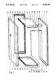
- FIG. 1is an exploded view of a first embodiment of the casing components of an equipment cabinet, where the components are provided with peripheral, rectangular bevels;
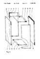
- FIG. 2is likewise an exploded view of a second embodiment of the casing components of an equipment cabinet, where the components are provided with inwardly bent, peripheral edge strips;
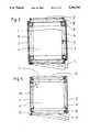
- FIG. 3is a horizontal sectional view of an equipment cabinet equipped with the casing components of FIG. 1;
- FIG. 4is a horizontal sectional view of a second equipment cabinet equipped with the casing components of FIG. 2;
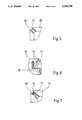
- FIG. 5depicts a first corner configuration of the equipment cabinet shown in FIG. 4;
- FIG. 6depicts a second corner configuration of the equipment cabinet shown in FIG. 4;
- FIG. 7depicts a third alternative for the configuration of the corner of the equipment cabinet of FIG. 4.
- the equipment cabinet for accommodating electronic and electrical insertable unitsis essentially composed of a self-supporting, block-shaped rack 1 or 1', respectively (FIGS. 3 to 5) for holding the insertable units and of a plurality of metal casing components, namely (FIGS. 1 and 2) side walls 2 and 2', a rear wall 3 or 3', respectively, a door 4 or 4', respectively, a top 5 or 5', respectively, and a bottom 6 or 6', respectively.
- These casing componentsare made of sheet steel and their surfaces are appropriately protected against corrosion on their exterior and interior faces by one or several coats of lacquer 7.
- Rack 1(FIG. 3) which is assembled by welding of steel pipes having a square cross section is composed of four vertical posts 8 and eight horizontal traverse members 9; it is equipped with rails, telescopes, supports, and struts (all not shown) for fastening the insertable units (not illustrated).
- the rack 1' shown in FIG. 4is assembled with the aid of profiled steel rods 10 that have an essentially U-shaped cross section and is equipped in a corresponding manner.
- racks 1 and 1'are also provided with electrically non-conductive coatings 11 produced, for example, by spray lacquering or dipping.
- the casing components shown in FIG. 1, the two identical side walls 2, the rear wall 3, the door 4, the top 5 and the bottom 6, the latter identical to the top,are configured as very low rectangular troughs. At all of their edges 12, they are provided with peripheral, rectangular bevels 13 of the same height which abut at the four corners 14 and are there connected with one another. For the two side walls 2 and top 5 as well as bottom 6, beveled edge strips 15 of the same width are attached to these bevels 13 so as to project outwardly at a right angle and extend in each case only to the vicinity of corners 14 so that top 5 and bottom 6 can be pushed into side wall 2.
- casing components 2, 3, 4, 5 and 6are provided with electrically well conducting contact faces 16.
- these contact faces 16are arranged to face one another.
- the mutually corresponding bare metal contact faces 16are formed by their unlacquered abutting edges.
- Corresponding, but broader, contact faces 16are also provided on the interior faces of side members 2 along their edges 12 (as indicated in FIG. 1) as well as at the side bevels 13 of top 5 and bottom 6.
- Spring-elastic contact strips 17are arranged between the conductive contact faces 16 of facing casing components 2, 3, 4, 5 and 6 (see FIG. 3). These contact strips 17, which are made of a well conducting material, are elastic braided metal structures in the form of flexible cords or rows or strips of spring contacts of a suitable high quality, corrosion protected metal. These contact strips 17 are each electrically conductively fastened in a suitable manner on the contact faces 16 of the edge strips 15 of one of the two juxtaposed casing components 2, 3, 4, 5 and 6 where they form a gap that must be sealed against electromagnetic radiation.
- the assemblable casing componentsare also given a trough-shaped configuration, with the two side walls 2', the rear wall 3', the door 4', the top 5' and the bottom 6' being provided with peripheral edge strips 15' which are bent inwardly at an angle 18 of forty-five angular degrees (FIG. 4) so as to form a high-frequency-tight shield that is closed on all sides around rack 1'.
- peripheral edge strips 15'as well are connected with one another (for example, by welding) at the corners 14' of casing components 2', 3', 4', 5' and 6'.
- casing components 2' to 6'are provided with peripheral, bare metal and thus electrically well conducting contact faces 16' which are arranged in opposing pairs and thus correspond with one another.
- Contact strips 17' of a spring-elastic, electrically well conducting materialare disposed between the strip-shaped contact faces 16'.
- Such contact strips 17'support the edge strips 15' of both side walls 2', rear wall 3' and door 4', while top 5' and bottom 6' are provided only with contact faces 16'.
- the assembled casing components 2' to 6'form a completely closed shield in the form of a block-shaped box which surrounds rack 1 and which excellently shields the inserted units held therein against extraneous electromagnetic waves in the sense of a Faraday cage and almost completely attenuates the escape of such waves that are generated within the insertable units themselves, as long as all existing gaps between casing components 2' to 6' are completely and thoroughly sealed by means of contact strips 17'.
- contact strips 17'are configured appropriately--have an approximately S-shaped cross section--they may be fastened (see FIG. 5) by clamping them to edge strips 15'. Differently configured contact strips 17' can be fastened in a different manner in that they are fastened to rack 1 by clamping (see FIG. 6).
- FIG. 7shows a further embodiment in which additional rubber-elastic sealing strips 19 are arranged parallel to the metal contact strips 17' so as to provide a good mechanical seal.
- the independent shielding composed of the assembled casing components 2, 2' to 6, 6'is fastened to rack 1, 1' in any desired manner, for example by screwing or clamping. Since this can be accomplished very easily, the equipment cabinets can be selectively or even subsequently provided with one of the two described shielding arrangements. It is understood that simple additional measures are required to shield, for example, the plates of hinges 20 for doors 4, 4' which are brought out through the casing and which--since they require efforts that are commonplace in the trade--need not be described here.
Landscapes
- Engineering & Computer Science (AREA)
- Microelectronics & Electronic Packaging (AREA)
- Power Engineering (AREA)
- Shielding Devices Or Components To Electric Or Magnetic Fields (AREA)
- Mounting Of Printed Circuit Boards And The Like (AREA)
- Details Of Audible-Bandwidth Transducers (AREA)
Abstract
Description
Claims (10)
Applications Claiming Priority (2)
| Application Number | Priority Date | Filing Date | Title |
|---|---|---|---|
| DE4127468 | 1991-08-20 | ||
| DE4127468ADE4127468C1 (en) | 1991-08-20 | 1991-08-20 |
Publications (1)
| Publication Number | Publication Date |
|---|---|
| US5294748Atrue US5294748A (en) | 1994-03-15 |
Family
ID=6438650
Family Applications (1)
| Application Number | Title | Priority Date | Filing Date |
|---|---|---|---|
| US07/931,474Expired - LifetimeUS5294748A (en) | 1991-08-20 | 1992-08-19 | Equipment cabinet |
Country Status (5)
| Country | Link |
|---|---|
| US (1) | US5294748A (en) |
| EP (1) | EP0528240B1 (en) |
| JP (1) | JP2603032B2 (en) |
| AT (1) | ATE114104T1 (en) |
| DE (2) | DE4127468C1 (en) |
Cited By (58)
| Publication number | Priority date | Publication date | Assignee | Title |
|---|---|---|---|---|
| US5550324A (en)* | 1995-02-23 | 1996-08-27 | Fluke Corporation | Environmental sealing system for electronic instruments |
| WO2000004805A2 (en) | 1998-07-23 | 2000-02-03 | The Foxboro Company | Equipment storage apparatus |
| USD425031S (en)* | 1999-01-22 | 2000-05-16 | The Foxboro Company | Equipment cabinet |
| US6163454A (en)* | 1999-02-22 | 2000-12-19 | Hewlett-Packard Company | Electromagnetic interference (EMI) shield for electrical components, an internal EMI barrier, and a storage enclosure for electrical/electronic components |
| US6207893B1 (en)* | 1998-08-27 | 2001-03-27 | Schroff Gmbh | High frequency shielded duct |
| US6213577B1 (en) | 1998-07-23 | 2001-04-10 | The Foxboro Company | Equipment storage apparatus |
| US6320124B1 (en)* | 1999-10-26 | 2001-11-20 | Veterans General Hospital - Taipei | Electrophysiological faraday box |
| US20040047121A1 (en)* | 2002-09-10 | 2004-03-11 | John Hope | Apparatus for EMI/RFI hardening of off-the-shelf computers |
| EP1463167A3 (en)* | 2003-03-28 | 2006-08-09 | Knürr AG | Cabinet |
| WO2006117816A1 (en)* | 2005-04-29 | 2006-11-09 | Bticino S.P.A. | Electrical connection device between a panel and an electrical switchboard |
| US20070064391A1 (en)* | 2005-09-19 | 2007-03-22 | Chatsworth Products, Inc. | Air diverter for directing air upwardly in an equipment enclosure |
| US20070064389A1 (en)* | 2005-09-19 | 2007-03-22 | Chatsworth Products, Inc. | Ducted exhaust equipment enclosure |
| US20080316702A1 (en)* | 2007-05-17 | 2008-12-25 | Chatsworth Products, Inc. | Exhaust air duct with adjustable filler panel assemblies |
| US20090227197A1 (en)* | 2008-02-14 | 2009-09-10 | Chatsworth Products, Inc. | Air directing device |
| US20090273915A1 (en)* | 2008-01-07 | 2009-11-05 | Dean Jr David Lee | Apparatus and method for organizing cables in a cabinet |
| US20100061059A1 (en)* | 2005-09-19 | 2010-03-11 | Chatsworth Products, Inc. | Ducted exhaust equipment enclosure |
| US7804685B2 (en) | 2005-09-19 | 2010-09-28 | Chatsworth Products, Inc. | Ducted exhaust equipment enclosure |
| US20100248610A1 (en)* | 2009-03-30 | 2010-09-30 | Panduit Corp. | Adjustable Vertical Exhaust Duct |
| USD630173S1 (en) | 2009-04-20 | 2011-01-04 | Chatsworth Products, Inc. | Cover for electronic equipment cabinet |
| US20110000574A1 (en)* | 2009-07-02 | 2011-01-06 | Panduit Corp. | Adjustable Vertical Exhaust Duct |
| USD632660S1 (en) | 2009-04-20 | 2011-02-15 | Chatsworth Products, Inc. | Cover for electronic equipment cabinet |
| USD649833S1 (en)* | 2008-11-07 | 2011-12-06 | Whirlpool Corporation | Appliance with a front having the appearance of chamfered sides with rounded edges |
| USD653908S1 (en)* | 2011-09-22 | 2012-02-14 | Whirlpool Corporation | Appliance with a front having the appearance of chamfered sides with rounded edges |
| CN102883571A (en)* | 2011-07-11 | 2013-01-16 | 通用电气公司 | A housing assembly and a method of assembling the same |
| USD684128S1 (en) | 2012-02-10 | 2013-06-11 | Chatsworth Products, Inc. | Containment aisle door |
| US20130242508A1 (en)* | 2010-11-09 | 2013-09-19 | Abb Ag | Electrical switch cabinet |
| US8653363B2 (en) | 2010-06-01 | 2014-02-18 | Chatsworth Products, Inc. | Magnetic filler panel for use in airflow control system in electronic equipment enclosure |
| US20140180059A1 (en)* | 2012-11-06 | 2014-06-26 | Imris Inc. | Method for MR-Guided Brachytherapy with Consistent Patient Positioning |
| US8787023B2 (en) | 2010-09-10 | 2014-07-22 | Chatsworth Products, Inc. | Rail mounting clamp for electronic equipment enclosure |
| US8901438B2 (en) | 2010-09-10 | 2014-12-02 | Chatsworth Products, Inc. | Electronic equipment cabinet structure |
| US9055677B2 (en) | 2010-09-10 | 2015-06-09 | Chatsworth Products, Inc. | Cable pass-through panel for electronic equipment enclosure |
| US9560777B2 (en) | 2010-11-08 | 2017-01-31 | Chatsworth Products, Inc. | Door closer mechanism for hot/cold aisle air containment room |
| US9572286B2 (en) | 2013-01-11 | 2017-02-14 | Chatsworth Products, Inc. | Modular thermal isolation barrier for data processing equipment structure |
| US9655259B2 (en) | 2011-12-09 | 2017-05-16 | Chatsworth Products, Inc. | Data processing equipment structure |
| WO2018160149A1 (en)* | 2017-03-03 | 2018-09-07 | Lande Endüstri̇yel Metal Ürünler Sanayi̇ Ve Ti̇caret Anoni̇m Şi̇rketi̇ | Easy-to-mount modular rack cabinet |
| US10869415B1 (en) | 2019-07-19 | 2020-12-15 | Dell Products L.P. | System and method for operating electromagnetically isolated device |
| US10917996B1 (en) | 2019-07-19 | 2021-02-09 | Dell Products L.P. | System and method for device level thermal management and electromagnetic interference management |
| US10980159B2 (en) | 2019-07-19 | 2021-04-13 | Dell Products L.P. | System and method for managing multiple connections |
| US11122718B2 (en) | 2019-07-19 | 2021-09-14 | Dell Products L.P. | System and method for device level electromagnetic interference management |
| US11129307B2 (en) | 2019-07-19 | 2021-09-21 | Dell Products L.P. | System and method for managing thermal states of devices |
| US11132038B2 (en) | 2019-07-19 | 2021-09-28 | Dell Products L.P. | System and method for thermal management of shadowed devices |
| US11147194B2 (en) | 2019-08-21 | 2021-10-12 | Dell Products L.P. | System and method for managing electromagnetic interference |
| US11143682B2 (en) | 2019-07-19 | 2021-10-12 | Dell Products L.P. | System and method for communicating externally from an electromagnetic interference suppressed volume |
| US11212928B2 (en) | 2005-09-19 | 2021-12-28 | Chatsworth Products, Inc. | Vertical exhaust duct for electronic equipment enclosure |
| US11234350B2 (en)* | 2019-08-21 | 2022-01-25 | Dell Products L.P. | System and method for isolated device access |
| US11234347B2 (en) | 2019-07-19 | 2022-01-25 | Dell Products L.P. | System and method for physical management of devices |
| US11246231B2 (en) | 2012-02-10 | 2022-02-08 | Chatsworth Products, Inc. | Door closer mechanism for hot/cold aisle air containment room |
| US11259446B2 (en) | 2005-09-19 | 2022-02-22 | Chatsworth Products, Inc. | Vertical exhaust duct for electronic equipment enclosure |
| US11378608B2 (en) | 2019-07-19 | 2022-07-05 | Dell Products L.P. | System and method for device state determination |
| US11399450B2 (en) | 2019-07-19 | 2022-07-26 | Dell Products L.P. | System and method for managing electromagnetic interference |
| US11622458B1 (en) | 2020-12-15 | 2023-04-04 | Chatsworth Products, Inc. | Brush port assembly and method for installing same |
| US11644425B2 (en) | 2019-07-19 | 2023-05-09 | Dell Products L.P. | System and method for optical state determination |
| US11678458B1 (en) | 2020-12-15 | 2023-06-13 | Chatsworth Products, Inc. | Slidable mounting hardware for electronic equipment enclosure and method for installing same |
| US11818860B1 (en) | 2020-12-15 | 2023-11-14 | Chatsworth Products, Inc. | Frame structure for electronic equipment enclosure |
| US11920392B1 (en) | 2021-02-02 | 2024-03-05 | Chatsworth Products, Inc. | Electrical bonding door hinges |
| US20240090665A1 (en)* | 2022-09-20 | 2024-03-21 | Acorn Engineering Company | Ligature resistant cabinet |
| US12004336B2 (en) | 2019-07-19 | 2024-06-04 | Dell Products L.P. | System and method for thermal management and electromagnetic interference management |
| US12048108B1 (en) | 2020-12-15 | 2024-07-23 | Chatsworth Products, Inc. | Caster attachment system using mating features |
Families Citing this family (11)
| Publication number | Priority date | Publication date | Assignee | Title |
|---|---|---|---|---|
| DE4311246C1 (en)* | 1993-04-06 | 1994-03-31 | Schroff Gmbh | Housing for electronic equipment with HF sealing - provided by formed leaf spring contact clips that are located of ribs of frame bars and engage fill in panels |
| DE9313327U1 (en)* | 1993-09-04 | 1993-11-18 | Telenorma Gmbh, 60327 Frankfurt | Housing arrangement for a telecommunications switching system |
| US5513996A (en)* | 1994-09-20 | 1996-05-07 | Motorola, Inc. | Clip and method therefor |
| DE19614692C1 (en)* | 1996-04-13 | 1997-06-05 | Schroff Gmbh | Electronics cabinet |
| GB2327182B (en)* | 1997-07-14 | 2001-05-02 | Dsc Telecom Lp | A housing for an equipment rack |
| DE19823651C1 (en)* | 1998-05-27 | 1999-10-28 | Schaefer Gehaeusesysteme Gmbh | Electromagnetic screening connection between metal components, e.g. for electronic apparatus casing |
| DE19856776A1 (en)* | 1998-11-30 | 2000-06-08 | Siemens Ag | Control cabinet with a protective device against electromagnetic radiation |
| JP5645680B2 (en)* | 2011-01-20 | 2014-12-24 | 株式会社岡本工作機械製作所 | Waterproof enclosure for control panels installed on machine tools |
| KR101340041B1 (en)* | 2013-03-12 | 2013-12-10 | 성소희 | Flame for flower bed |
| CN106714500A (en)* | 2017-02-28 | 2017-05-24 | 天津凯发电气股份有限公司 | Multifunctional cabinet of electrified railway protection measuring and control device |
| CN107668975A (en)* | 2017-10-16 | 2018-02-09 | 北京海尔云厨科技有限公司 | Storage device with shielding door body |
Citations (19)
| Publication number | Priority date | Publication date | Assignee | Title |
|---|---|---|---|---|
| US3217058A (en)* | 1961-11-02 | 1965-11-09 | Continental Oil Co | Preparation of alpha-olefins from aluminum alkoxides |
| US3253082A (en)* | 1964-08-28 | 1966-05-24 | Nova Ind Inc | Electrical shielding structure |
| DE1465247A1 (en)* | 1964-01-17 | 1969-05-08 | Bbc Brown Boveri & Cie | Electric switch cabinet in fully insulated construction |
| DE2134815A1 (en)* | 1970-07-17 | 1972-01-20 | Ibm | Housing arrangement for electrical devices for shielding against electrostatic and magnetostatic radiation |
| DE7442069U (en)* | 1975-05-28 | Licentia Patent Verwaltungs Gmbh | High-frequency-tight assembly | |
| DE2829255A1 (en)* | 1978-07-04 | 1980-01-17 | Metzeler Kautschuk | Sealing and screening strip for joints in electric equipment - has metal screening cord bonded to elastic sealing profile |
| US4300016A (en)* | 1979-03-23 | 1981-11-10 | Compagnie Industrielle Des Telecommunications Cit-Alcatel | Screened box |
| DE3129582A1 (en)* | 1981-07-28 | 1983-02-17 | Licentia Patent-Verwaltungs-Gmbh, 6000 Frankfurt | Electromagnetically screened chamber of modular construction |
| US4626615A (en)* | 1985-04-08 | 1986-12-02 | Keene Corporation | RF expansion joint for an electrically sealed enclosure |
| US4631641A (en)* | 1985-07-18 | 1986-12-23 | Northern Telecom Limited | Electronic apparatus with electro-magnetic interference screening |
| US4643319A (en)* | 1983-12-09 | 1987-02-17 | Rittal-Werk Rudolf Loh Gmbh & Co. Kg | Framework for a switchboard cabinet |
| DE3604860A1 (en)* | 1986-02-15 | 1987-08-20 | Licentia Gmbh | ARRANGEMENT FOR HIGH-FREQUENCY-DENSITY SHIELDING OF THE FRONT PANEL OF A DEVICE INSERT |
| EP0255587A2 (en)* | 1986-07-25 | 1988-02-10 | Meto-Bau AG | Seal against high frequency currents and casing sealed against the same |
| DE8803544U1 (en)* | 1988-03-16 | 1988-07-07 | Standard Elektrik Lorenz Ag, 7000 Stuttgart | Subrack with shielded plug-in modules |
| US4760496A (en)* | 1986-04-08 | 1988-07-26 | Rittal-Werk Rudolf Loh Gmbh & Co. Kg | Switch cabinet with frame support |
| US4777565A (en)* | 1986-03-15 | 1988-10-11 | Unisys Corporation | Shielded equipment enclosure |
| EP0306694A1 (en)* | 1987-09-11 | 1989-03-15 | Siemens Aktiengesellschaft | Shielding device for shielded cabins, enclosures, casings or the like |
| EP0340773A2 (en)* | 1988-05-06 | 1989-11-08 | Alcatel SEL Aktiengesellschaft | Gasket for an electromagnetically shielded casing |
| EP0427550A2 (en)* | 1989-11-13 | 1991-05-15 | Gichner Systems Group, Inc. | Gasket for providing EMI/RFI shielding |
Family Cites Families (10)
| Publication number | Priority date | Publication date | Assignee | Title |
|---|---|---|---|---|
| US3034844A (en)* | 1958-01-21 | 1962-05-15 | Amco Eng | Enclosure |
| DE1884362U (en)* | 1963-06-14 | 1963-12-12 | Bbc Brown Boveri & Cie | INSTALLATION CONTROL CABINET IN A FULLY INSULATED DESIGN. |
| JPS55147795U (en)* | 1979-04-07 | 1980-10-23 | ||
| JPS5623039A (en)* | 1980-03-31 | 1981-03-04 | Toshiba Corp | Fm digital synthesizer receiver |
| JPS58160166A (en)* | 1982-03-19 | 1983-09-22 | Fuji Xerox Co Ltd | Thermal recording head and its manufacturing device |
| DE8308487U1 (en)* | 1983-03-22 | 1983-06-16 | Siemens AG, 1000 Berlin und 8000 München | Cover part for upright housing, in particular for data technology |
| DE8521461U1 (en)* | 1985-07-26 | 1986-11-27 | Siemens AG, 1000 Berlin und 8000 München | Electronics cabinet |
| JPS62145397U (en)* | 1986-03-07 | 1987-09-12 | ||
| JPH0611590Y2 (en)* | 1987-11-30 | 1994-03-23 | 日本電気株式会社 | Electromagnetic shield structure for electronic device housing |
| DE9100798U1 (en)* | 1991-01-24 | 1991-04-11 | Schroff Gmbh, 75334 Straubenhardt | Metal housings for electronic devices |
- 1991
- 1991-08-20DEDE4127468Apatent/DE4127468C1/denot_activeExpired - Lifetime
- 1992
- 1992-08-01ATAT92113154Tpatent/ATE114104T1/ennot_activeIP Right Cessation
- 1992-08-01EPEP92113154Apatent/EP0528240B1/ennot_activeRevoked
- 1992-08-01DEDE59200772Tpatent/DE59200772D1/ennot_activeExpired - Lifetime
- 1992-08-19USUS07/931,474patent/US5294748A/ennot_activeExpired - Lifetime
- 1992-08-19JPJP4219987Apatent/JP2603032B2/ennot_activeExpired - Lifetime
Patent Citations (20)
| Publication number | Priority date | Publication date | Assignee | Title |
|---|---|---|---|---|
| DE7442069U (en)* | 1975-05-28 | Licentia Patent Verwaltungs Gmbh | High-frequency-tight assembly | |
| US3217058A (en)* | 1961-11-02 | 1965-11-09 | Continental Oil Co | Preparation of alpha-olefins from aluminum alkoxides |
| DE1465247A1 (en)* | 1964-01-17 | 1969-05-08 | Bbc Brown Boveri & Cie | Electric switch cabinet in fully insulated construction |
| US3253082A (en)* | 1964-08-28 | 1966-05-24 | Nova Ind Inc | Electrical shielding structure |
| DE2134815A1 (en)* | 1970-07-17 | 1972-01-20 | Ibm | Housing arrangement for electrical devices for shielding against electrostatic and magnetostatic radiation |
| DE2829255A1 (en)* | 1978-07-04 | 1980-01-17 | Metzeler Kautschuk | Sealing and screening strip for joints in electric equipment - has metal screening cord bonded to elastic sealing profile |
| US4300016A (en)* | 1979-03-23 | 1981-11-10 | Compagnie Industrielle Des Telecommunications Cit-Alcatel | Screened box |
| DE3129582A1 (en)* | 1981-07-28 | 1983-02-17 | Licentia Patent-Verwaltungs-Gmbh, 6000 Frankfurt | Electromagnetically screened chamber of modular construction |
| US4643319A (en)* | 1983-12-09 | 1987-02-17 | Rittal-Werk Rudolf Loh Gmbh & Co. Kg | Framework for a switchboard cabinet |
| US4626615A (en)* | 1985-04-08 | 1986-12-02 | Keene Corporation | RF expansion joint for an electrically sealed enclosure |
| US4631641A (en)* | 1985-07-18 | 1986-12-23 | Northern Telecom Limited | Electronic apparatus with electro-magnetic interference screening |
| DE3604860A1 (en)* | 1986-02-15 | 1987-08-20 | Licentia Gmbh | ARRANGEMENT FOR HIGH-FREQUENCY-DENSITY SHIELDING OF THE FRONT PANEL OF A DEVICE INSERT |
| US4777565A (en)* | 1986-03-15 | 1988-10-11 | Unisys Corporation | Shielded equipment enclosure |
| US4760496A (en)* | 1986-04-08 | 1988-07-26 | Rittal-Werk Rudolf Loh Gmbh & Co. Kg | Switch cabinet with frame support |
| EP0255587A2 (en)* | 1986-07-25 | 1988-02-10 | Meto-Bau AG | Seal against high frequency currents and casing sealed against the same |
| EP0306694A1 (en)* | 1987-09-11 | 1989-03-15 | Siemens Aktiengesellschaft | Shielding device for shielded cabins, enclosures, casings or the like |
| DE8803544U1 (en)* | 1988-03-16 | 1988-07-07 | Standard Elektrik Lorenz Ag, 7000 Stuttgart | Subrack with shielded plug-in modules |
| EP0340773A2 (en)* | 1988-05-06 | 1989-11-08 | Alcatel SEL Aktiengesellschaft | Gasket for an electromagnetically shielded casing |
| EP0427550A2 (en)* | 1989-11-13 | 1991-05-15 | Gichner Systems Group, Inc. | Gasket for providing EMI/RFI shielding |
| US5020866A (en)* | 1989-11-13 | 1991-06-04 | Gichner Systems Group, Inc. | Enclosure for housing electronic components |
Non-Patent Citations (4)
| Title |
|---|
| "F-Geschirmte Schaltschrank-Systeme", Rittal Handbook 26, Jun. 1990, pp. 170-171, 254, 258-259. |
| F Geschirmte Schaltschrank Systeme , Rittal Handbook 26, Jun. 1990, pp. 170 171, 254, 258 259.* |
| HF Brochure from Rittal, (Feb. 1991) pp. 6 7.* |
| HF Brochure from Rittal, (Feb. 1991) pp. 6-7. |
Cited By (139)
| Publication number | Priority date | Publication date | Assignee | Title |
|---|---|---|---|---|
| US5550324A (en)* | 1995-02-23 | 1996-08-27 | Fluke Corporation | Environmental sealing system for electronic instruments |
| WO2000004805A2 (en) | 1998-07-23 | 2000-02-03 | The Foxboro Company | Equipment storage apparatus |
| US6213577B1 (en) | 1998-07-23 | 2001-04-10 | The Foxboro Company | Equipment storage apparatus |
| US6207893B1 (en)* | 1998-08-27 | 2001-03-27 | Schroff Gmbh | High frequency shielded duct |
| USD425031S (en)* | 1999-01-22 | 2000-05-16 | The Foxboro Company | Equipment cabinet |
| US6163454A (en)* | 1999-02-22 | 2000-12-19 | Hewlett-Packard Company | Electromagnetic interference (EMI) shield for electrical components, an internal EMI barrier, and a storage enclosure for electrical/electronic components |
| US6320124B1 (en)* | 1999-10-26 | 2001-11-20 | Veterans General Hospital - Taipei | Electrophysiological faraday box |
| US20040047121A1 (en)* | 2002-09-10 | 2004-03-11 | John Hope | Apparatus for EMI/RFI hardening of off-the-shelf computers |
| EP1463167A3 (en)* | 2003-03-28 | 2006-08-09 | Knürr AG | Cabinet |
| WO2005027613A1 (en)* | 2003-09-08 | 2005-03-24 | John Hope | Apparatus for emi/rfi hardening of off-the-shelf computers |
| WO2006117816A1 (en)* | 2005-04-29 | 2006-11-09 | Bticino S.P.A. | Electrical connection device between a panel and an electrical switchboard |
| CN101180780B (en)* | 2005-04-29 | 2012-03-21 | 卜提奇诺有限公司 | Electrical connection device between a panel and an electrical switchboard |
| US11678447B2 (en) | 2005-09-19 | 2023-06-13 | Chatsworth Products, Inc. | Vertical exhaust duct for electronic equipment enclosure |
| US11547020B2 (en) | 2005-09-19 | 2023-01-03 | Chatsworth Products, Inc. | Vertical exhaust duct for electronic equipment enclosure |
| US8737068B2 (en) | 2005-09-19 | 2014-05-27 | Chatsworth Products, Inc. | Ducted exhaust equipment enclosure |
| US11259446B2 (en) | 2005-09-19 | 2022-02-22 | Chatsworth Products, Inc. | Vertical exhaust duct for electronic equipment enclosure |
| US7542287B2 (en) | 2005-09-19 | 2009-06-02 | Chatsworth Products, Inc. | Air diverter for directing air upwardly in an equipment enclosure |
| US10123462B2 (en) | 2005-09-19 | 2018-11-06 | Chatsworth Products, Inc. | Ducted exhaust equipment enclosure |
| US20090239461A1 (en)* | 2005-09-19 | 2009-09-24 | Chatsworth Products, Inc. | Air diverter for directing air upwardly in an equipment enclosure |
| US11785745B2 (en) | 2005-09-19 | 2023-10-10 | Chatsworth Products, Inc. | Vertical exhaust duct for electronic equipment enclosure |
| US20100061059A1 (en)* | 2005-09-19 | 2010-03-11 | Chatsworth Products, Inc. | Ducted exhaust equipment enclosure |
| US12082379B2 (en) | 2005-09-19 | 2024-09-03 | Chatsworth Products, Inc. | Vertical exhaust duct for electronic equipment enclosure |
| US20070064391A1 (en)* | 2005-09-19 | 2007-03-22 | Chatsworth Products, Inc. | Air diverter for directing air upwardly in an equipment enclosure |
| US7804685B2 (en) | 2005-09-19 | 2010-09-28 | Chatsworth Products, Inc. | Ducted exhaust equipment enclosure |
| US9974198B2 (en) | 2005-09-19 | 2018-05-15 | Chatsworth Products, Inc. | Vertical exhaust duct for electronic equipment enclosure |
| US11212928B2 (en) | 2005-09-19 | 2021-12-28 | Chatsworth Products, Inc. | Vertical exhaust duct for electronic equipment enclosure |
| US9801309B2 (en) | 2005-09-19 | 2017-10-24 | Chatsworth Products, Inc. | Ducted exhaust equipment enclosure |
| US10334761B2 (en) | 2005-09-19 | 2019-06-25 | Chatsworth Products, Inc. | Method of venting heated air from electronic equipment enclosure |
| US20070064389A1 (en)* | 2005-09-19 | 2007-03-22 | Chatsworth Products, Inc. | Ducted exhaust equipment enclosure |
| US10440847B2 (en) | 2005-09-19 | 2019-10-08 | Chatsworth Products, Inc. | Vertical exhaust duct for electronic equipment enclosure |
| US7952869B2 (en) | 2005-09-19 | 2011-05-31 | Chatsworth Products, Inc. | Air diverter for directing air upwardly in an equipment enclosure |
| US8107238B2 (en) | 2005-09-19 | 2012-01-31 | Chatsworth Products, Inc. | Ducted exhaust equipment enclosure |
| US10568239B2 (en) | 2005-09-19 | 2020-02-18 | Chatsworth Products, Inc. | Method of venting heated air from electronic equipment enclosure |
| US8730665B2 (en) | 2005-09-19 | 2014-05-20 | Chatsworth Products, Inc. | Vertical exhaust duct |
| US10624232B2 (en) | 2005-09-19 | 2020-04-14 | Chatsworth Products, Inc. | Ducted exhaust equipment enclosure |
| US9119329B2 (en) | 2005-09-19 | 2015-08-25 | Chatsworth Products, Inc. | Ducted exhaust equipment enclosure |
| US9084369B2 (en) | 2005-09-19 | 2015-07-14 | Chatsworth Products, Inc. | Vertical exhaust duct |
| US10791640B2 (en) | 2005-09-19 | 2020-09-29 | Chatsworth Products, Inc. | Vertical exhaust duct for electronic equipment enclosure |
| US10765037B2 (en) | 2005-09-19 | 2020-09-01 | Chatsworth Products, Inc. | Vertical exhaust duct for electronic equipment enclosure |
| US20080316702A1 (en)* | 2007-05-17 | 2008-12-25 | Chatsworth Products, Inc. | Exhaust air duct with adjustable filler panel assemblies |
| US20110148261A1 (en)* | 2007-05-17 | 2011-06-23 | Donowho D Brian | Exhaust air duct with adjustable filler panel assemblies |
| US7839635B2 (en) | 2007-05-17 | 2010-11-23 | Chatsworth Products, Inc. | Exhaust air duct with adjustable filler panel assemblies |
| US7746637B2 (en) | 2007-05-17 | 2010-06-29 | Chatsworth Products, Inc. | Electronic equipment enclosure with exhaust air duct and adjustable filler panel assemblies |
| US7697285B2 (en) | 2007-05-17 | 2010-04-13 | Chatsworth Products, Inc. | Electronic equipment enclosure with exhaust air duct and adjustable filler panel assemblies |
| US20090129013A1 (en)* | 2007-05-17 | 2009-05-21 | Chatsworth Products, Inc. | Electronic equipment enclosure with exhaust air duct and adjustable filler panel assemblies |
| US8405984B2 (en) | 2007-05-17 | 2013-03-26 | Chatsworth Products, Inc. | Exhaust air duct with adjustable filler panel assemblies |
| US20080316703A1 (en)* | 2007-05-17 | 2008-12-25 | Chatsworth Products, Inc. | Electronic equipment enclosure with exhaust air duct and adjustable filler panel assemblies |
| US20090273915A1 (en)* | 2008-01-07 | 2009-11-05 | Dean Jr David Lee | Apparatus and method for organizing cables in a cabinet |
| US20110211329A1 (en)* | 2008-01-07 | 2011-09-01 | Chatsworth Products, Inc. | Apparatus and method for organizing cables in a cabinet |
| US7974105B2 (en) | 2008-01-07 | 2011-07-05 | Chatsworth Products, Inc. | Apparatus and method for organizing cables in a cabinet |
| US20110211328A1 (en)* | 2008-01-07 | 2011-09-01 | Chatsworth Products, Inc. | Apparatus and method for organizing cables in a cabinet |
| US8437147B2 (en) | 2008-01-07 | 2013-05-07 | Chatsworth Products, Inc. | Kit for organizing cables in a cabinet |
| US8411465B2 (en) | 2008-01-07 | 2013-04-02 | Chatsworth Products, Inc. | Method for organizing cables in a cabinet to reduce impeded airflow |
| US10133320B2 (en) | 2008-02-14 | 2018-11-20 | Chatsworth Products, Inc. | Air directing device |
| US11132035B2 (en) | 2008-02-14 | 2021-09-28 | Chatsworth Products, Inc. | Air directing device |
| US11880247B2 (en) | 2008-02-14 | 2024-01-23 | Chatsworth Products, Inc. | Air directing device |
| US20090227197A1 (en)* | 2008-02-14 | 2009-09-10 | Chatsworth Products, Inc. | Air directing device |
| US11464132B2 (en) | 2008-09-08 | 2022-10-04 | Chatsworth Products, Inc. | Ducted exhaust equipment enclosure |
| US8040673B2 (en) | 2008-09-08 | 2011-10-18 | Chatsworth Products, Inc. | Ducted exhaust equipment enclosure |
| US20110019362A1 (en)* | 2008-09-08 | 2011-01-27 | William Krietzman | Ducted exhaust equipment enclosure |
| US12052843B2 (en) | 2008-09-08 | 2024-07-30 | Chatsworth Products, Inc. | Ducted exhaust equipment enclosure |
| US11706898B2 (en) | 2008-09-08 | 2023-07-18 | Chatsworth Products, Inc. | Ducted exhaust equipment enclosure |
| USD649833S1 (en)* | 2008-11-07 | 2011-12-06 | Whirlpool Corporation | Appliance with a front having the appearance of chamfered sides with rounded edges |
| USD651462S1 (en)* | 2008-11-07 | 2012-01-03 | Whirlpool Corporation | Appliance with a front having the appearance of chamfered sides with rounded edges |
| USD657191S1 (en)* | 2008-11-07 | 2012-04-10 | Whirlpool Corporation | Appliance with a front having the appearance of chamfered sides with rounded edges |
| USD652677S1 (en)* | 2008-11-07 | 2012-01-24 | Whirpool Corporation | Appliance with a front having the appearance of chamfered sides with rounded edges |
| USD651461S1 (en)* | 2008-11-07 | 2012-01-03 | Whirlpool Corporation | Appliance with a front having the appearance of chamfered sides with rounded edges |
| US9210833B2 (en) | 2009-03-30 | 2015-12-08 | Panduit Corp. | Adjustable vertical exhaust duct |
| US20100248610A1 (en)* | 2009-03-30 | 2010-09-30 | Panduit Corp. | Adjustable Vertical Exhaust Duct |
| USD632660S1 (en) | 2009-04-20 | 2011-02-15 | Chatsworth Products, Inc. | Cover for electronic equipment cabinet |
| USD630173S1 (en) | 2009-04-20 | 2011-01-04 | Chatsworth Products, Inc. | Cover for electronic equipment cabinet |
| US20110000574A1 (en)* | 2009-07-02 | 2011-01-06 | Panduit Corp. | Adjustable Vertical Exhaust Duct |
| US8973951B2 (en) | 2009-07-02 | 2015-03-10 | Panduit Corp. | Adjustable vertical exhaust duct |
| US8653363B2 (en) | 2010-06-01 | 2014-02-18 | Chatsworth Products, Inc. | Magnetic filler panel for use in airflow control system in electronic equipment enclosure |
| US12108553B2 (en) | 2010-09-10 | 2024-10-01 | Chatsworth Products, Inc. | Cable pass-through panel for electronic equipment enclosure |
| US9781852B2 (en) | 2010-09-10 | 2017-10-03 | Chatsworth Products, Inc. | Cable pass-through panel for electronic equipment enclosure |
| US9814159B2 (en) | 2010-09-10 | 2017-11-07 | Chatsworth Products, Inc. | Rail seal for electronic equipment enclosure |
| US10178784B2 (en) | 2010-09-10 | 2019-01-08 | Chatsworth Products, Inc. | Rail seal for electronic equipment enclosure |
| US10237994B2 (en) | 2010-09-10 | 2019-03-19 | Chatsworth Products, Inc. | Vertical mounting rail with cable management features |
| US11792948B2 (en) | 2010-09-10 | 2023-10-17 | Chatsworth Products, Inc. | Cable pass-through panel for electronic equipment enclosure |
| US9980400B2 (en) | 2010-09-10 | 2018-05-22 | Chatsworth Products, Inc. | Rail seal for electronic equipment enclosure |
| US8787023B2 (en) | 2010-09-10 | 2014-07-22 | Chatsworth Products, Inc. | Rail mounting clamp for electronic equipment enclosure |
| US9642270B2 (en) | 2010-09-10 | 2017-05-02 | Chatsworth Products, Inc. | Rail seal for electronic equipment enclosure |
| US11039543B2 (en) | 2010-09-10 | 2021-06-15 | Chatsworth Products, Inc. | Vertical mounting rail with cable management features |
| US10588227B2 (en) | 2010-09-10 | 2020-03-10 | Chatsworth Products, Inc. | Vertical mounting rail with cable management features |
| US11464123B2 (en) | 2010-09-10 | 2022-10-04 | Chatsworth Products, Inc. | Method of adapting an electronic equipment enclosure for cable management |
| US9408326B2 (en) | 2010-09-10 | 2016-08-02 | Chatsworth Products, Inc. | Electronic equipment cabinet structure |
| US10653025B2 (en) | 2010-09-10 | 2020-05-12 | Chatsworth Products, Inc. | Cable pass-through panel for electronic equipment enclosure |
| US9055677B2 (en) | 2010-09-10 | 2015-06-09 | Chatsworth Products, Inc. | Cable pass-through panel for electronic equipment enclosure |
| US8901438B2 (en) | 2010-09-10 | 2014-12-02 | Chatsworth Products, Inc. | Electronic equipment cabinet structure |
| US10362695B2 (en) | 2010-11-08 | 2019-07-23 | Chatsworth Products, Inc. | Door closer mechanism for hot/cold aisle air containment room |
| US9560777B2 (en) | 2010-11-08 | 2017-01-31 | Chatsworth Products, Inc. | Door closer mechanism for hot/cold aisle air containment room |
| US20130242508A1 (en)* | 2010-11-09 | 2013-09-19 | Abb Ag | Electrical switch cabinet |
| US9559501B2 (en)* | 2011-07-11 | 2017-01-31 | General Electric Company | Housing assembly and method of assembling same |
| CN102883571A (en)* | 2011-07-11 | 2013-01-16 | 通用电气公司 | A housing assembly and a method of assembling the same |
| USD653908S1 (en)* | 2011-09-22 | 2012-02-14 | Whirlpool Corporation | Appliance with a front having the appearance of chamfered sides with rounded edges |
| US9655259B2 (en) | 2011-12-09 | 2017-05-16 | Chatsworth Products, Inc. | Data processing equipment structure |
| US10709039B2 (en) | 2011-12-09 | 2020-07-07 | Chatsworth Products, Inc. | Data processing equipment structure |
| US11246231B2 (en) | 2012-02-10 | 2022-02-08 | Chatsworth Products, Inc. | Door closer mechanism for hot/cold aisle air containment room |
| USD684128S1 (en) | 2012-02-10 | 2013-06-11 | Chatsworth Products, Inc. | Containment aisle door |
| US9575148B2 (en)* | 2012-11-06 | 2017-02-21 | Imris Inc. | Method for MR-guided brachytherapy with consistent patient positioning |
| US20140180059A1 (en)* | 2012-11-06 | 2014-06-26 | Imris Inc. | Method for MR-Guided Brachytherapy with Consistent Patient Positioning |
| US9572286B2 (en) | 2013-01-11 | 2017-02-14 | Chatsworth Products, Inc. | Modular thermal isolation barrier for data processing equipment structure |
| US9795060B2 (en) | 2013-01-11 | 2017-10-17 | Chatsworth Products, Inc. | Modular thermal isolation barrier for data processing equipment structure |
| US10375861B2 (en) | 2013-01-11 | 2019-08-06 | Chatsworth Products, Inc. | Modular thermal isolation barrier for data processing equipment structure |
| US12063758B2 (en) | 2013-01-11 | 2024-08-13 | Chatsworth Products, Inc. | Modular thermal isolation barrier for data processing equipment structure |
| US10595442B2 (en) | 2013-01-11 | 2020-03-17 | Chatsworth Products, Inc. | Data processing equipment structure |
| US11647610B2 (en) | 2013-01-11 | 2023-05-09 | Chatsworth Products, Inc. | Modular thermal isolation barrier for data processing equipment structure |
| WO2018160149A1 (en)* | 2017-03-03 | 2018-09-07 | Lande Endüstri̇yel Metal Ürünler Sanayi̇ Ve Ti̇caret Anoni̇m Şi̇rketi̇ | Easy-to-mount modular rack cabinet |
| US11234347B2 (en) | 2019-07-19 | 2022-01-25 | Dell Products L.P. | System and method for physical management of devices |
| US11143682B2 (en) | 2019-07-19 | 2021-10-12 | Dell Products L.P. | System and method for communicating externally from an electromagnetic interference suppressed volume |
| US10917996B1 (en) | 2019-07-19 | 2021-02-09 | Dell Products L.P. | System and method for device level thermal management and electromagnetic interference management |
| US11399450B2 (en) | 2019-07-19 | 2022-07-26 | Dell Products L.P. | System and method for managing electromagnetic interference |
| US11378608B2 (en) | 2019-07-19 | 2022-07-05 | Dell Products L.P. | System and method for device state determination |
| US11644425B2 (en) | 2019-07-19 | 2023-05-09 | Dell Products L.P. | System and method for optical state determination |
| US10980159B2 (en) | 2019-07-19 | 2021-04-13 | Dell Products L.P. | System and method for managing multiple connections |
| US11906438B2 (en) | 2019-07-19 | 2024-02-20 | Dell Products L.P. | System and method for optical state determination |
| US11132038B2 (en) | 2019-07-19 | 2021-09-28 | Dell Products L.P. | System and method for thermal management of shadowed devices |
| US11122718B2 (en) | 2019-07-19 | 2021-09-14 | Dell Products L.P. | System and method for device level electromagnetic interference management |
| US10869415B1 (en) | 2019-07-19 | 2020-12-15 | Dell Products L.P. | System and method for operating electromagnetically isolated device |
| US12004336B2 (en) | 2019-07-19 | 2024-06-04 | Dell Products L.P. | System and method for thermal management and electromagnetic interference management |
| US11129307B2 (en) | 2019-07-19 | 2021-09-21 | Dell Products L.P. | System and method for managing thermal states of devices |
| US11147194B2 (en) | 2019-08-21 | 2021-10-12 | Dell Products L.P. | System and method for managing electromagnetic interference |
| US11234350B2 (en)* | 2019-08-21 | 2022-01-25 | Dell Products L.P. | System and method for isolated device access |
| US11678456B1 (en) | 2020-12-15 | 2023-06-13 | Chatsworth Products, Inc. | Slidable mounting hardware for electronic equipment enclosure and method for installing same |
| US12089363B1 (en) | 2020-12-15 | 2024-09-10 | Chatsworth Products, Inc. | Slidable mounting hardware for electronic equipment enclosure |
| US11818861B1 (en) | 2020-12-15 | 2023-11-14 | Chatsworth Products, Inc. | Frame structure for electronic equipment enclosure |
| US12342486B1 (en) | 2020-12-15 | 2025-06-24 | Chatsworth Products, Inc. | Port barrier assembly and method for installing same |
| US12160974B1 (en) | 2020-12-15 | 2024-12-03 | Chatsworth Products, Inc. | Frame structure for electronic equipment enclosure |
| US11818862B1 (en) | 2020-12-15 | 2023-11-14 | Chatsworth Products, Inc. | Frame structure for electronic equipment enclosure |
| US12048108B1 (en) | 2020-12-15 | 2024-07-23 | Chatsworth Products, Inc. | Caster attachment system using mating features |
| US11818860B1 (en) | 2020-12-15 | 2023-11-14 | Chatsworth Products, Inc. | Frame structure for electronic equipment enclosure |
| US11678458B1 (en) | 2020-12-15 | 2023-06-13 | Chatsworth Products, Inc. | Slidable mounting hardware for electronic equipment enclosure and method for installing same |
| US11627677B1 (en) | 2020-12-15 | 2023-04-11 | Chatsworth Products, Inc. | Brush port assembly and method for installing same |
| US11903156B1 (en) | 2020-12-15 | 2024-02-13 | Chatsworth Products, Inc. | Brush port assembly and method for installing same |
| US11622458B1 (en) | 2020-12-15 | 2023-04-04 | Chatsworth Products, Inc. | Brush port assembly and method for installing same |
| US11920392B1 (en) | 2021-02-02 | 2024-03-05 | Chatsworth Products, Inc. | Electrical bonding door hinges |
| US12428888B1 (en) | 2021-02-02 | 2025-09-30 | Chatsworth Products, Inc. | Electrical bonding door hinges |
| US20240090665A1 (en)* | 2022-09-20 | 2024-03-21 | Acorn Engineering Company | Ligature resistant cabinet |
Also Published As
| Publication number | Publication date |
|---|---|
| DE4127468C1 (en) | 1992-10-08 |
| EP0528240B1 (en) | 1994-11-09 |
| EP0528240A1 (en) | 1993-02-24 |
| JPH05235578A (en) | 1993-09-10 |
| ATE114104T1 (en) | 1994-11-15 |
| JP2603032B2 (en) | 1997-04-23 |
| DE59200772D1 (en) | 1994-12-15 |
Similar Documents
| Publication | Publication Date | Title |
|---|---|---|
| US5294748A (en) | Equipment cabinet | |
| US4760496A (en) | Switch cabinet with frame support | |
| US5600091A (en) | HF shielded electrical enclosures | |
| US4853790A (en) | Electromagnetic and electrostatic shielding for electronic equipment | |
| GB2308016A (en) | Shielding in electronics cabinets | |
| US3504095A (en) | Shielding gaskets | |
| US6225554B1 (en) | EMI shielded enclosure | |
| US4705916A (en) | EMI gasket retaining mechanism for electronic equipment | |
| KR0135530B1 (en) | Connector | |
| US5266054A (en) | Sealed and filtered header receptacle | |
| US6303854B1 (en) | EMI shielded telecommunications enclosure | |
| CA1318014C (en) | Sealing enclosures against electromagnetic interference | |
| US4786758A (en) | Door shield for shielded enclosure | |
| JPH0267000A (en) | Radio frequency disturbance shielding device | |
| US4761516A (en) | Electromagnetic interference shielding device | |
| US5585599A (en) | Housing for electronic devices | |
| US4572597A (en) | Cover for rack cabinets, particularly for data processing equipment | |
| US5829615A (en) | Equipment case | |
| WO1994030035A1 (en) | Insulator means for suppressing interference radiation in an electric field | |
| GB2174551A (en) | Screened rack | |
| KR100286396B1 (en) | Shielded module support structure | |
| US4726636A (en) | Cover for rack cabinets, particularly for data processing equipment | |
| US5796039A (en) | Weatherproofing of electrical connections with terminals on outdoor panels | |
| RU2269879C1 (en) | Radio-electronic block | |
| JPH0241906Y2 (en) |
Legal Events
| Date | Code | Title | Description |
|---|---|---|---|
| AS | Assignment | Owner name:SCHROFF GMBH, GERMANY Free format text:ASSIGNMENT OF ASSIGNORS INTEREST.;ASSIGNORS:SCHWENK, HANS MARTIN;POHL, KURT;HULLER, GERHARD;REEL/FRAME:006339/0592;SIGNING DATES FROM 19920918 TO 19921005 | |
| STCF | Information on status: patent grant | Free format text:PATENTED CASE | |
| AS | Assignment | Owner name:PNTA INDUSTRIEBEDARF GMBH, GERMANY Free format text:ASSIGNMENT OF ASSIGNORS INTEREST;ASSIGNOR:SCHROFF GMBH;REEL/FRAME:007436/0141 Effective date:19940228 Owner name:SCHROFF GMBH, GERMANY Free format text:CHANGE OF NAME;ASSIGNOR:PNTA INDUSTRIEBEDARF GMBH;REEL/FRAME:007436/0134 Effective date:19950120 | |
| FEPP | Fee payment procedure | Free format text:PAYOR NUMBER ASSIGNED (ORIGINAL EVENT CODE: ASPN); ENTITY STATUS OF PATENT OWNER: LARGE ENTITY | |
| FPAY | Fee payment | Year of fee payment:4 | |
| FPAY | Fee payment | Year of fee payment:8 | |
| FPAY | Fee payment | Year of fee payment:12 | |
| FEPP | Fee payment procedure | Free format text:PAYER NUMBER DE-ASSIGNED (ORIGINAL EVENT CODE: RMPN); ENTITY STATUS OF PATENT OWNER: LARGE ENTITY Free format text:PAYOR NUMBER ASSIGNED (ORIGINAL EVENT CODE: ASPN); ENTITY STATUS OF PATENT OWNER: LARGE ENTITY |