US5293993A - Syringe sealing container - Google Patents
Syringe sealing containerDownload PDFInfo
- Publication number
- US5293993A US5293993AUS07/715,365US71536591AUS5293993AUS 5293993 AUS5293993 AUS 5293993AUS 71536591 AUS71536591 AUS 71536591AUS 5293993 AUS5293993 AUS 5293993A
- Authority
- US
- United States
- Prior art keywords
- syringe
- base
- closure cover
- needle
- cover
- Prior art date
- Legal status (The legal status is an assumption and is not a legal conclusion. Google has not performed a legal analysis and makes no representation as to the accuracy of the status listed.)
- Expired - Fee Related
Links
- 238000007789sealingMethods0.000title1
- 239000012530fluidSubstances0.000claimsabstractdescription8
- 239000000565sealantSubstances0.000claimsdescription10
- 239000003112inhibitorSubstances0.000claims3
- 239000004033plasticSubstances0.000abstractdescription11
- 229920003023plasticPolymers0.000abstractdescription11
- 230000002401inhibitory effectEffects0.000abstract1
- 238000007373indentationMethods0.000description10
- 239000000463materialSubstances0.000description10
- 238000000034methodMethods0.000description8
- 230000000994depressogenic effectEffects0.000description6
- 208000012266Needlestick injuryDiseases0.000description5
- 201000010099diseaseDiseases0.000description3
- 208000037265diseases, disorders, signs and symptomsDiseases0.000description3
- 238000004519manufacturing processMethods0.000description3
- 208000030507AIDSDiseases0.000description2
- 230000005802health problemEffects0.000description2
- 238000012986modificationMethods0.000description2
- 230000004048modificationEffects0.000description2
- -1polypropylenePolymers0.000description2
- 239000004800polyvinyl chlorideSubstances0.000description2
- 229920000915polyvinyl chloridePolymers0.000description2
- 230000001681protective effectEffects0.000description2
- QTBSBXVTEAMEQO-UHFFFAOYSA-MAcetateChemical compoundCC([O-])=OQTBSBXVTEAMEQO-UHFFFAOYSA-M0.000description1
- 241000894006BacteriaSpecies0.000description1
- 239000004698PolyethyleneSubstances0.000description1
- 239000004743PolypropyleneSubstances0.000description1
- 239000004793PolystyreneSubstances0.000description1
- 241000700605VirusesSpecies0.000description1
- 239000011248coating agentSubstances0.000description1
- 238000000576coating methodMethods0.000description1
- 238000000748compression mouldingMethods0.000description1
- 239000002920hazardous wasteSubstances0.000description1
- 208000006454hepatitisDiseases0.000description1
- 231100000283hepatitisToxicity0.000description1
- 239000007924injectionSubstances0.000description1
- 238000001746injection mouldingMethods0.000description1
- 238000000465mouldingMethods0.000description1
- 229920000573polyethylenePolymers0.000description1
- 229920001155polypropylenePolymers0.000description1
- 229920002223polystyrenePolymers0.000description1
- 230000000284resting effectEffects0.000description1
- 238000004513sizingMethods0.000description1
- 239000000126substanceSubstances0.000description1
- 238000007666vacuum formingMethods0.000description1
Images


Classifications
- A—HUMAN NECESSITIES
- A61—MEDICAL OR VETERINARY SCIENCE; HYGIENE
- A61M—DEVICES FOR INTRODUCING MEDIA INTO, OR ONTO, THE BODY; DEVICES FOR TRANSDUCING BODY MEDIA OR FOR TAKING MEDIA FROM THE BODY; DEVICES FOR PRODUCING OR ENDING SLEEP OR STUPOR
- A61M5/00—Devices for bringing media into the body in a subcutaneous, intra-vascular or intramuscular way; Accessories therefor, e.g. filling or cleaning devices, arm-rests
- A61M5/178—Syringes
- A61M5/31—Details
- A61M5/32—Needles; Details of needles pertaining to their connection with syringe or hub; Accessories for bringing the needle into, or holding the needle on, the body; Devices for protection of needles
- A61M5/3205—Apparatus for removing or disposing of used needles or syringes, e.g. containers; Means for protection against accidental injuries from used needles
- A—HUMAN NECESSITIES
- A61—MEDICAL OR VETERINARY SCIENCE; HYGIENE
- A61B—DIAGNOSIS; SURGERY; IDENTIFICATION
- A61B50/00—Containers, covers, furniture or holders specially adapted for surgical or diagnostic appliances or instruments, e.g. sterile covers
- A61B50/30—Containers specially adapted for packaging, protecting, dispensing, collecting or disposing of surgical or diagnostic appliances or instruments
- A61B50/36—Containers specially adapted for packaging, protecting, dispensing, collecting or disposing of surgical or diagnostic appliances or instruments for collecting or disposing of used articles
- A61B50/362—Containers specially adapted for packaging, protecting, dispensing, collecting or disposing of surgical or diagnostic appliances or instruments for collecting or disposing of used articles for sharps
- B—PERFORMING OPERATIONS; TRANSPORTING
- B65—CONVEYING; PACKING; STORING; HANDLING THIN OR FILAMENTARY MATERIAL
- B65D—CONTAINERS FOR STORAGE OR TRANSPORT OF ARTICLES OR MATERIALS, e.g. BAGS, BARRELS, BOTTLES, BOXES, CANS, CARTONS, CRATES, DRUMS, JARS, TANKS, HOPPERS, FORWARDING CONTAINERS; ACCESSORIES, CLOSURES, OR FITTINGS THEREFOR; PACKAGING ELEMENTS; PACKAGES
- B65D43/00—Lids or covers for rigid or semi-rigid containers
- B65D43/14—Non-removable lids or covers
- B65D43/16—Non-removable lids or covers hinged for upward or downward movement
- B65D43/162—Non-removable lids or covers hinged for upward or downward movement the container, the lid and the hinge being made of one piece
- B—PERFORMING OPERATIONS; TRANSPORTING
- B65—CONVEYING; PACKING; STORING; HANDLING THIN OR FILAMENTARY MATERIAL
- B65D—CONTAINERS FOR STORAGE OR TRANSPORT OF ARTICLES OR MATERIALS, e.g. BAGS, BARRELS, BOTTLES, BOXES, CANS, CARTONS, CRATES, DRUMS, JARS, TANKS, HOPPERS, FORWARDING CONTAINERS; ACCESSORIES, CLOSURES, OR FITTINGS THEREFOR; PACKAGING ELEMENTS; PACKAGES
- B65D75/00—Packages comprising articles or materials partially or wholly enclosed in strips, sheets, blanks, tubes or webs of flexible sheet material, e.g. in folded wrappers
- B65D75/28—Articles or materials wholly enclosed in composite wrappers, i.e. wrappers formed by associating or interconnecting two or more sheets or blanks
- B65D75/30—Articles or materials enclosed between two opposed sheets or blanks having their margins united, e.g. by pressure-sensitive adhesive, crimping, heat-sealing, or welding
- B65D75/32—Articles or materials enclosed between two opposed sheets or blanks having their margins united, e.g. by pressure-sensitive adhesive, crimping, heat-sealing, or welding one or both sheets or blanks being recessed to accommodate contents
- B65D75/321—Both sheets being recessed
- B65D75/322—Both sheets being recessed and forming one compartment
- A—HUMAN NECESSITIES
- A61—MEDICAL OR VETERINARY SCIENCE; HYGIENE
- A61B—DIAGNOSIS; SURGERY; IDENTIFICATION
- A61B50/00—Containers, covers, furniture or holders specially adapted for surgical or diagnostic appliances or instruments, e.g. sterile covers
- A61B2050/005—Containers, covers, furniture or holders specially adapted for surgical or diagnostic appliances or instruments, e.g. sterile covers with a lid or cover
- A61B2050/0051—Containers, covers, furniture or holders specially adapted for surgical or diagnostic appliances or instruments, e.g. sterile covers with a lid or cover closable by rotation
- A61B2050/0056—Containers, covers, furniture or holders specially adapted for surgical or diagnostic appliances or instruments, e.g. sterile covers with a lid or cover closable by rotation about a lateral axis in the lid plane
- A—HUMAN NECESSITIES
- A61—MEDICAL OR VETERINARY SCIENCE; HYGIENE
- A61B—DIAGNOSIS; SURGERY; IDENTIFICATION
- A61B50/00—Containers, covers, furniture or holders specially adapted for surgical or diagnostic appliances or instruments, e.g. sterile covers
- A61B50/30—Containers specially adapted for packaging, protecting, dispensing, collecting or disposing of surgical or diagnostic appliances or instruments
- A61B50/31—Carrying cases or bags, e.g. doctors' bags
- A61B2050/311—Cases
- B—PERFORMING OPERATIONS; TRANSPORTING
- B65—CONVEYING; PACKING; STORING; HANDLING THIN OR FILAMENTARY MATERIAL
- B65D—CONTAINERS FOR STORAGE OR TRANSPORT OF ARTICLES OR MATERIALS, e.g. BAGS, BARRELS, BOTTLES, BOXES, CANS, CARTONS, CRATES, DRUMS, JARS, TANKS, HOPPERS, FORWARDING CONTAINERS; ACCESSORIES, CLOSURES, OR FITTINGS THEREFOR; PACKAGING ELEMENTS; PACKAGES
- B65D2251/00—Details relating to container closures
- B65D2251/10—Details of hinged closures
- B65D2251/1016—Means for locking the closure in closed position
- B65D2251/1033—Protuberances and cavities provided on a horizontal flange respectively of the container or base and the closure, and penetrating one into the other, e.g. of the press-button type
Definitions
- the present inventionrelates to an apparatus and method for securing and disposing of hypodermic syringes with needles. More particularly, the present invention relates to an apparatus and method for encasing a hypodermic syringe, with needle, in a sealed environment which will reduce the possibility of contact by the handler with the secured contents.
- the present inventionrelates generally to the safe disposal of hypodermic syringes and needles.
- medical personnel and othersin the course of using and disposing of hypodermic syringes with needles, have suffered needle stick injuries which have presented serious health problems.
- Diseasessuch as hepatitis and AIDS may be transmitted by needle stick injuries. These diseases can lead to serious health problems, even the possibility of death.
- medical personnel who have contact with hypodermic syringes with needlesmust take increasing care to insure their safety.
- a retractable syringeretracts and retains the possibly contaminated needle into the barrel of the syringe, and thus, protectively isolates the needle from further human contact.
- some retractable syringesit is possible for some retractable syringes to leak contaminated fluids or residue through the opening where the needle is retracted into the syringe barrel. If excess contaminated fluids or residue leak, there is a risk of the contaminating virus or bacteria contaminating other medical tools or equipment in the area, and possibly infecting persons who subsequently come into contact with such tools, equipment, or the syringe. This existing risk of exposure to contaminated material gives rise to the need for further syringe and needle disposal protection.
- the disposal container of the present inventioncomprises a molded set of pieces of flexible, transparent, plastic material including a syringe cavity base and a well closure cover which are connected by a hinge along the central vertical axis.
- the well closure covercontains two identical raised circular tabs across from the hinge.
- the syringe cavity basecontains two identical circular receiver tabs, which are joined with the raised circular tabs to secure the disposal container in the closed position.
- the plasticOn the well closure cover, the plastic is molded in a raised elongated rectangular position with the center hollowed to approximately half the depth of the raised portion of the rectangle.
- An optional coatingmay be placed on the rectangular, built-up portion to provide a seal with the syringe cavity base when closed. The seal, once created between the well closure cover and the syringe cavity base, is extremely difficult to breach.
- the syringe cavity basecontains an indention which is slightly larger than the raised plastic portion on the well closure cover.
- the base and the coverfit tightly and securely together to form a seal around that portion of the container.
- the well closure coveris thus used to cover and secure the syringe cavity base, with the raised, hollowed surface serving as a safety container to inhibit or reduce the possibility of contaminated fluids or residue from leaking from the disposal container.
- the indented portion of the syringe cavity basethere is a further indention which serves to contain the syringe and needle.
- the bottom of the indentionis sized to accommodate most sizes of syringe plungers and corresponding finger grips.
- the elongated portion of the indented cavityis sized to be wide and deep enough to accommodate most syringe barrels.
- an incline planeis located which angles up to a needle containing indention of the syringe cavity base. The incline plane allows for differing sizes of syringe and needle configurations to be housed in the container safely.
- the needle indentionis shallow and is used to accommodate the needle portion of the syringe.
- the length of this indentionis sized to be adequate for accommodating most medical and veterinary needles.
- the disposal containersin their sealed state, are collected by messenger service for disposal at proper sites.
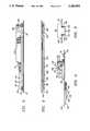
- FIG. 1is a profile view of the disposal container in the fully extended, open position
- FIG. 2is a top view of the open disposal container
- FIG. 3is a side view of the syringe cavity base, shown from the horizontal plane;
- FIG. 4is a side view of the well closure cover, shown from the horizontal plane;
- FIG. 5is a frontal view of the disposal container
- FIG. 6is a cross section view of the hinge which connects the syringe cavity base and the well closure cover.
- the present inventiondiscloses a hypodermic syringe disposal container.
- the container 5comprises a syringe cavity base 10 and a well closure cover 15.
- the base 10 and the cover 15are connected by a continuous hinge 20.
- the syringe cavity base 10is typically 167 mm long and 61 mm wide.
- the syringe cavity base 10includes a flat portion 25 with two depressed circular indentations 30, 35 set in from the end edge 11, 16 of base 12 and top 17, respectively, and the side edge 13 at side 14 of the syringe cavity base 10. Both indentations 30 and 35 are the same size typically with a diameter of 8 mm and a depth of 4 mm.
- Indentation 30is typically located indented 23 mm from the end edge of base 12 of the syringe cavity base 10 and is typically located 8 mm set in from the side edge 13 of side 14 of the syringe cavity base 10.
- Indentation 35is similarly located typically 23 mm indented from the opposing end edge 16 of top 17 of the syringe cavity base 10, and 8 mm from the side edge 13 of side 14 of the syringe cavity base 10.
- the syringe cavity base 10includes an elongated depressed indentation 27, which is centrally located between indentations 30 and 35 and is typically 85 mm long, 4 mm wide, and 3 mm deep.
- the syringe cavity base 10includes a depression 40 which is rectangular in shape with rounded corners. Depression 40 is typically located 7 mm from the end edge 11 of base 12 of syringe base 10, 18 mm from the side edge 13 of side 14 of syringe base 10, 7 mm from the top edge 16 of top 17 of syringe base 10, and 3 mm from the hinge edge 21 of hinge 20. Depression 40 is typically 38 mm wide and 150 mm long. Depression 40 is surrounded by walls 45 which are typically 6 mm deep. Depression 40 includes a floor 42, needle depression 50, barrel depression 100, and plunger depression 125. Needle depression 50 is centrally located inside of depression 40, typically 2 mm from the top edge 41 of the initial depression 40.
- Needle depression 50is centrally located along the vertical axis of depression 40 and is typically 6 mm deeper than the floor 42 of depression 40. Needle depression 50 has a top edge 51 and extends for typically 60 mm along the floor 42. Needle depression 50 is walled at the top by a curved linear portion 55 and surrounded further by symmetrical walls 60, 65, all with a typical depth of 6 mm measured from the floor 42 of depression 40.
- An inclined plane 70is formed in floor 42 starting from top edge 51. Inclined plane 70 is symmetrically located on the vertical central axis of needle depression 50. The inclined plane 70 is lined by walls 75 and 80 which are shaped as symmetrical elongated triangles. Typically inclined plane 70 begins 24 mm from the top edge 51 of depression 50 and angles downward. Inclined plane 70 is typically 15 mm long and 6 mm wide. The angle of inclination of inclined plane 70 is typically 15 degrees measured from the horizontal plane of needle depression 50.
- Inclined plane 70adjoins barrel depression wall 90.
- Wall 90is curvilinear in the corners, and forms the top wall for barrel depression 100.
- Wall 90is typically 16 mm wide.
- Cavity wall 90extends from depression floor 51 to barrel depression floor 101.
- Barrel depression floor 101is rectangular in shape and is surrounded by walls 90, 115, and 120.
- Barrel depression walls 115, 120which are typically 16 mm deep measured from depression floor 42, are symmetric and typically extend 65 mm from barrel depression wall 90 to where they adjoin wall 130, which surrounds plunger depression floor 126.
- Plunger depression floor 126is typically 30 mm wide and 16 mm long, centered along the vertical axis. Plunger depression floor 126 is typically 12 mm deep measured from depression floor 42, and is surrounded by plunger depression wall 130, which is typically 12 mm high and curvilinear in all four corners. Plunger depression wall 130 is sloped outward towards depression floor 42.
- the well closure cover 15comprises cover base 150 with two raised circular indentions 155 and 160.
- Well closure cover 15includes end edges 151, 156 at base 152 and top edge 157, respectively, and side edge 154.
- the well closure cover 15is typically 167 mm long and 62 mm wide. Both indentations 155 and 160 are the same size typically with a diameter of 7.5 mm and a depth of 3.5 mm.
- Indentation 155is typically located 23 mm indented in from the end edge 151 of base 152 of the well closure cover 15 and is also typically indented 8 mm from the side edge 153 of side 154 of the well closure cover 15.
- lndentation 160is similarly typically located 23 mm from the opposing end edge 156 of top edge 157 of well closure cover 15 and is also typically located 8 mm indented in from the side edge 153 of side 154 of the well closure cover 15.
- the well closure cover 15includes two protuberances 155, 160 and an elongated raised protuberance 162.
- Raise protuberance 162is centrally located between protuberances 155, 160 and is typically 85 mm long, 4 mm wide, and 3 mm deep.
- Cover base 150 of the well closure cover 15extends inward to a built-up wall 165 which is rectangular in shape with rounded corners and is hollow in the center.
- Wall 165is typically located 7 mm from the end edge 151 of base 152 of cover 15, 18 mm from the side edge 153 of side 154 of cover 15, 7 mm from the top edge 156 of top 157 of cover 15, and 3 mm from the hinge edge 142 of hinge 20.
- the height of wall 165is typically 5 mm, width is 37 mm, and length is 149 mm.
- the wall top 170adjoins wall 165 and is the same rectangular typically shape with a width of 2 mm extending towards the center of the rectangle.
- the hollow portion 185, in the center of the raised portionis formed by wall 175, with a typical depth of 2.5 mm, and by base 180. Wall 175 angles down to base 180 which is typically 25 mm wide and 137 mm long.
- An optional sealant 190may be placed on built-up wall 165, wall top 170, and as shown in FIG. 2, on a 2-5 mm boarder around the base of built-up wall 165 on base 150, where built-up wall 165 adjoins cover base 150 of well closure cover 15.
- the sealant 190is a sticky substance which will adhere to the plastic material upon contact. When contact is made between the sealant and the plastic material, a seal is created which is difficult to breach.
- FIG. 6shows a cross-section of hinge 20, which includes two depressed hinge sides 135 and 140, which are typically 2 mm wide and 155 mm long.
- Hinge side 135adjoins syringe cavity flat portion 25 at hinge edge 21 and adjoins hinge floor 140 at hinge edge 139.
- hinge side 40adjoins well closure cover flat portion 150 at hinge edge 142 and adjoins hinge floor 140 at hinge edge 144.
- Hinge floor 145is typically 4 mm wide and 155 mm long.
- Hinge 20is sufficiently elastic, due to the sizing of hinge sides 135, 140, and hinge floor 145, to allow the syringe cavity base 10 and the well closure cover 15 to remain in the open position, shown in FIG. 1, when the container 5 is held by only the syringe cavity base 10 or the well closure cover 15.
- methods available for producing such an objectinclude vacuum forming, injection, or compression molding of a plastic material.
- the plastic materials available for such moldinginclude polyvinyl chloride ("PVC"), polystyrene, polypropylene, acetate, polyethylene or any other thermo formed plastic.
- PVCpolyvinyl chloride
- the material utilizedshould be capable of forming and folding with reasonable ease, and be capable of retaining its flexible character after manufacture. The material utilized should also be capable of remaining transparent subsequent to manufacture.
- the hypodermic syringe and needle disposal container 5is to be opened, and preferably started open, for each subsequent opening may cause the material to yield and make subsequent openings easier to achieve, to the position shown in FIG. 1 with the syringe cavity base 10 open to the top.
- the handlerwill place the hypodermic syringe and needle into the syringe cavity base 10 with the plunger fitting in to plunger depression 125, the syringe barrel in to barrel depression floor 100, the needle into needle depression 50, with the connection between the syringe and the needle resting upon the inclined plane 70.
- the handlerUpon placing the hypodermic syringe and needle into the disposal container, the handler will fold over the well closure cover 15 by securing the syringe cavity base 10 with one hand and folding the well closure cover 15 around the axis of rotation which runs through hinge 20.
- the well closure coverwill be folded until the protuberances 154, 159 and outside wall 165 of the well closure cover 15 come in contact with the indentations 30, 35 and inside wall of the initial depression 45.
- the piecesare then pushed further together until the raised wall 165 of the well closure cover 15 is fully depressed into depression 40. If the sealant 190 is used, the last step will cause a tight seal to be formed between the well closure cover 15 and the syringe cavity base 10.
- the handlerIn order to further secure the well closure cove 15 to the syringe cavity base 10, the handler also forces protuberances 155, 160 into the depressed indentations 30, 35, respectively.
- the protuberances 155, 160are to be inserted until base 150 becomes flush with base 25 and the elongated portions 27, 162 are fully inserted and flush.
- the handlerWhen the disposal container is secure, the handler is then to lift the container and dispose of it in accordance with federal and state laws regarding the disposal of hazardous waste.
- the containershould be handled with due diligence and care.
Landscapes
- Health & Medical Sciences (AREA)
- Engineering & Computer Science (AREA)
- Life Sciences & Earth Sciences (AREA)
- Mechanical Engineering (AREA)
- Veterinary Medicine (AREA)
- General Health & Medical Sciences (AREA)
- Surgery (AREA)
- Chemical & Material Sciences (AREA)
- Biomedical Technology (AREA)
- Heart & Thoracic Surgery (AREA)
- Public Health (AREA)
- Composite Materials (AREA)
- Animal Behavior & Ethology (AREA)
- Environmental & Geological Engineering (AREA)
- Hematology (AREA)
- Anesthesiology (AREA)
- Nuclear Medicine, Radiotherapy & Molecular Imaging (AREA)
- Vascular Medicine (AREA)
- Medical Informatics (AREA)
- Molecular Biology (AREA)
- Infusion, Injection, And Reservoir Apparatuses (AREA)
Abstract
Description
The present invention relates to an apparatus and method for securing and disposing of hypodermic syringes with needles. More particularly, the present invention relates to an apparatus and method for encasing a hypodermic syringe, with needle, in a sealed environment which will reduce the possibility of contact by the handler with the secured contents.
The present invention relates generally to the safe disposal of hypodermic syringes and needles. In the past, medical personnel and others, in the course of using and disposing of hypodermic syringes with needles, have suffered needle stick injuries which have presented serious health problems. Diseases such as hepatitis and AIDS may be transmitted by needle stick injuries. These diseases can lead to serious health problems, even the possibility of death. In recent years due to the increasing threat of AIDS, medical personnel who have contact with hypodermic syringes with needles must take increasing care to insure their safety.
An existing method used for protecting the handler from possible needle stick accidents from hypodermic syringes with needles is through the use of the protective sheath which is typically provided for covering the hypodermic syringe needle prior to the use of the syringe. With non-retractable syringes, the protective sheath could be used to recover the needle after use. Unfortunately, such use causes an inherent risk of a needle stick injury due to the possible careless or improper handling of the needle or sheath, especially reinstalling the sheath over the needle. Moreover, the United States Center for Disease Control guidelines now recommend against the recapping of syringes with the needle sheaths after use.
Another existing method used to minimize the risk of needle stick injuries is the use of a retractable syringe. A retractable syringe retracts and retains the possibly contaminated needle into the barrel of the syringe, and thus, protectively isolates the needle from further human contact. However, it is possible for some retractable syringes to leak contaminated fluids or residue through the opening where the needle is retracted into the syringe barrel. If excess contaminated fluids or residue leak, there is a risk of the contaminating virus or bacteria contaminating other medical tools or equipment in the area, and possibly infecting persons who subsequently come into contact with such tools, equipment, or the syringe. This existing risk of exposure to contaminated material gives rise to the need for further syringe and needle disposal protection.
Others have conceived and prepared models of the idea of a rigid, opaque, plastic case made up of identical sides to hold a single size hypodermic syringe and needle. The plastic case has a hinge, and there are multiple protuberances on one side to be received by openings on the other side.
It is an object of the present invention to provide a safe method of disposal for used hypodermic syringes with needles through use of a disposal container which is secured by tabs which are not easily reopened, securing the contents inside the disposal container.
It is another object of the present invention to provide a disposal container which will hold the majority of sizes of syringe and needle configurations available to medical and veterinary personnel.
It is another object of the present invention to provide a method of disposal of the hypodermic syringe and needle by including a well closure cover which will inhibit the leaking of contaminated fluids or residue which may happen to leak out of the syringe barrel or needle after use.
It is another object of the present invention to encase a hypodermic syringe and needle in such a fashion where it is unlikely that the syringe and/or needle may shift sufficiently to breach the disposal container in any manner, at any time during the transportation or disposal of the container and its contents.
The disposal container of the present invention comprises a molded set of pieces of flexible, transparent, plastic material including a syringe cavity base and a well closure cover which are connected by a hinge along the central vertical axis. The well closure cover contains two identical raised circular tabs across from the hinge. The syringe cavity base contains two identical circular receiver tabs, which are joined with the raised circular tabs to secure the disposal container in the closed position.
On the well closure cover, the plastic is molded in a raised elongated rectangular position with the center hollowed to approximately half the depth of the raised portion of the rectangle. An optional coating may be placed on the rectangular, built-up portion to provide a seal with the syringe cavity base when closed. The seal, once created between the well closure cover and the syringe cavity base, is extremely difficult to breach.
The syringe cavity base contains an indention which is slightly larger than the raised plastic portion on the well closure cover. The base and the cover fit tightly and securely together to form a seal around that portion of the container. The well closure cover is thus used to cover and secure the syringe cavity base, with the raised, hollowed surface serving as a safety container to inhibit or reduce the possibility of contaminated fluids or residue from leaking from the disposal container.
Along the central axis of the indented portion of the syringe cavity base, there is a further indention which serves to contain the syringe and needle. The bottom of the indention is sized to accommodate most sizes of syringe plungers and corresponding finger grips. The elongated portion of the indented cavity is sized to be wide and deep enough to accommodate most syringe barrels. At the top of the elongated cavity, an incline plane is located which angles up to a needle containing indention of the syringe cavity base. The incline plane allows for differing sizes of syringe and needle configurations to be housed in the container safely. The needle indention is shallow and is used to accommodate the needle portion of the syringe. The length of this indention is sized to be adequate for accommodating most medical and veterinary needles.
The disposal containers, in their sealed state, are collected by messenger service for disposal at proper sites.
The accompanying drawings, which are incorporated in and constitute a part of the specification, in which like parts are given like reference referrals, illustrate preferred embodiments of the invention and, together with the general description of the invention given above and the detailed description of the preferred embodiments given below, serve to explain the principles of the invention.
FIG. 1: is a profile view of the disposal container in the fully extended, open position;
FIG. 2: is a top view of the open disposal container;
FIG. 3: is a side view of the syringe cavity base, shown from the horizontal plane;
FIG. 4: is a side view of the well closure cover, shown from the horizontal plane;
FIG. 5: is a frontal view of the disposal container;
FIG. 6: is a cross section view of the hinge which connects the syringe cavity base and the well closure cover.
The present invention discloses a hypodermic syringe disposal container. As shown in FIG. 1, thecontainer 5 comprises asyringe cavity base 10 and awell closure cover 15. Thebase 10 and thecover 15 are connected by acontinuous hinge 20.
Thesyringe cavity base 10 is typically 167 mm long and 61 mm wide. Thesyringe cavity base 10 includes aflat portion 25 with two depressedcircular indentations end edge base 12 and top 17, respectively, and theside edge 13 atside 14 of thesyringe cavity base 10. Bothindentations Indentation 30 is typically located indented 23 mm from the end edge ofbase 12 of thesyringe cavity base 10 and is typically located 8 mm set in from theside edge 13 ofside 14 of thesyringe cavity base 10.Indentation 35 is similarly located typically 23 mm indented from theopposing end edge 16 of top 17 of thesyringe cavity base 10, and 8 mm from theside edge 13 ofside 14 of thesyringe cavity base 10.
Thesyringe cavity base 10 includes an elongateddepressed indentation 27, which is centrally located betweenindentations
Thesyringe cavity base 10 includes adepression 40 which is rectangular in shape with rounded corners.Depression 40 is typically located 7 mm from theend edge 11 ofbase 12 ofsyringe base 10, 18 mm from theside edge 13 ofside 14 ofsyringe base 10, 7 mm from thetop edge 16 of top 17 ofsyringe base 10, and 3 mm from thehinge edge 21 ofhinge 20.Depression 40 is typically 38 mm wide and 150 mm long.Depression 40 is surrounded bywalls 45 which are typically 6 mm deep.Depression 40 includes afloor 42,needle depression 50,barrel depression 100, andplunger depression 125.Needle depression 50 is centrally located inside ofdepression 40, typically 2 mm from thetop edge 41 of theinitial depression 40.Needle depression 50 is centrally located along the vertical axis ofdepression 40 and is typically 6 mm deeper than thefloor 42 ofdepression 40.Needle depression 50 has atop edge 51 and extends for typically 60 mm along thefloor 42.Needle depression 50 is walled at the top by a curvedlinear portion 55 and surrounded further bysymmetrical walls floor 42 ofdepression 40. Aninclined plane 70 is formed infloor 42 starting fromtop edge 51.Inclined plane 70 is symmetrically located on the vertical central axis ofneedle depression 50. Theinclined plane 70 is lined bywalls inclined plane 70 begins 24 mm from thetop edge 51 ofdepression 50 and angles downward.Inclined plane 70 is typically 15 mm long and 6 mm wide. The angle of inclination ofinclined plane 70 is typically 15 degrees measured from the horizontal plane ofneedle depression 50.
As shown in FIG. 2, which shows thesyringe cavity base 10 on the left, raised towards the viewer, and the well closure cover 15 on the right, with thewell cavity 162 depressed into the page, the well closure cover 15 comprisescover base 150 with two raisedcircular indentions closure cover 15 includes end edges 151, 156 atbase 152 andtop edge 157, respectively, andside edge 154. The well closure cover 15 is typically 167 mm long and 62 mm wide. Bothindentations Indentation 155 is typically located 23 mm indented in from theend edge 151 ofbase 152 of thewell closure cover 15 and is also typically indented 8 mm from theside edge 153 ofside 154 of thewell closure cover 15.lndentation 160 is similarly typically located 23 mm from the opposingend edge 156 oftop edge 157 ofwell closure cover 15 and is also typically located 8 mm indented in from theside edge 153 ofside 154 of thewell closure cover 15.
The well closure cover 15 includes twoprotuberances protuberance 162. Raiseprotuberance 162 is centrally located betweenprotuberances
Anoptional sealant 190 may be placed on built-upwall 165,wall top 170, and as shown in FIG. 2, on a 2-5 mm boarder around the base of built-upwall 165 onbase 150, where built-upwall 165 adjoinscover base 150 ofwell closure cover 15. Thesealant 190 is a sticky substance which will adhere to the plastic material upon contact. When contact is made between the sealant and the plastic material, a seal is created which is difficult to breach.
To achieve the foregoing object, and in accordance with the purposes of the invention as embodied and broadly described herein, methods available for producing such an object include vacuum forming, injection, or compression molding of a plastic material. The plastic materials available for such molding include polyvinyl chloride ("PVC"), polystyrene, polypropylene, acetate, polyethylene or any other thermo formed plastic. The material utilized should be capable of forming and folding with reasonable ease, and be capable of retaining its flexible character after manufacture. The material utilized should also be capable of remaining transparent subsequent to manufacture.
The hypodermic syringe andneedle disposal container 5 is to be opened, and preferably started open, for each subsequent opening may cause the material to yield and make subsequent openings easier to achieve, to the position shown in FIG. 1 with thesyringe cavity base 10 open to the top. The handler will place the hypodermic syringe and needle into thesyringe cavity base 10 with the plunger fitting in to plungerdepression 125, the syringe barrel in tobarrel depression floor 100, the needle intoneedle depression 50, with the connection between the syringe and the needle resting upon theinclined plane 70. Upon placing the hypodermic syringe and needle into the disposal container, the handler will fold over the well closure cover 15 by securing thesyringe cavity base 10 with one hand and folding the well closure cover 15 around the axis of rotation which runs throughhinge 20. The well closure cover will be folded until theprotuberances 154, 159 and outsidewall 165 of the well closure cover 15 come in contact with theindentations initial depression 45. The pieces are then pushed further together until the raisedwall 165 of the well closure cover 15 is fully depressed intodepression 40. If thesealant 190 is used, the last step will cause a tight seal to be formed between thewell closure cover 15 and thesyringe cavity base 10.
In order to further secure thewell closure cove 15 to thesyringe cavity base 10, the handler also forcesprotuberances depressed indentations protuberances base 150 becomes flush withbase 25 and theelongated portions
When the disposal container is secure, the handler is then to lift the container and dispose of it in accordance with federal and state laws regarding the disposal of hazardous waste. The container should be handled with due diligence and care.
The embodiments set forth herein are merely illustrative and do not limit the scope of the invention or the details therein. It will be appreciated that many other modifications and improvements to the disclosure herein may be made without departing from the scope of the invention or the inventive concepts herein disclosed. Because many varying and different embodiments may be made within the scope of the inventive concept herein taught, including equivalent structures or materials hereafter thought of, and because many modifications may be more in the embodiments herein detailed in accordance with the descriptive requirements of the law, it is to be understood that the details herein are to be interpreted as illustrative and not in a limiting sense.
Claims (3)
1. A hypodermic syringe and needle disposal container for encasing a hypodermic syringe having a needle, a syringe body and a manipulation portion, comprising:
a syringe base having a cavity including containing means for receiving the hypodermic syringe;
a closure cover having a well and enclosing means for closing said containing means;
a hinge connected to said closure cover and said syringe base; and
a sealant on said closure cover having securing means for creating and maintaining a tight seal between said closure cover and said syringe base;;
wherein
said closure cover includes
a cover base;
a built-up portion;
said syringe base includes
an indented portion;
said built-up portion has an outer wall and a top surface sized to form a fluid flow inhibitor between said built-up portion and said indented portion; and
said sealant being placed on said cover base.
2. A hypodermic syringe and needle disposal container for encasing a hypodermic syringe having a needle, a syringe body and a manipulation portion, comprising:
a syringe base having a cavity including containing means for receiving the hypodermic syringe;
a closure cover having a well and enclosing means for closing said containing means;
a hinge connected to said closure cover and said syringe base; and
a sealant on said closure cover having securing means for creating and maintaining a tight seal between said closure cover and said syringe base;
wherein
said closure cover includes
a cover base;
a built-up portion;
said syringe base includes
an indented portion;
said built-up portion has an outer wall and a top surface sized to form a fluid flow inhibitor between said built-up portion and said indented portion; and
said sealant being placed on said outer wall.
3. A hypodermic syringe and needle disposal container for encasing a hypodermic syringe having a needle, a syringe body and a manipulation portion, comprising:
a syringe base having a cavity including containing means for receiving the hypodermic syringe;
a closure cover having a well and enclosing means for closing said containing means;
a hinge connected to said closure cover and said syringe base; and
a sealant on said closure cover having securing means for creating and maintaining a tight seal between said closure cover and said syringe base;
wherein
said closure cover includes
a cover base;
a built-up portion;
said syringe base includes
an indented portion;
said built-up portion has an outer wall and a top surface sized to form a fluid flow inhibitor between said built-up portion and said indented portion; and
said sealant being placed on said top surface.
Priority Applications (1)
| Application Number | Priority Date | Filing Date | Title |
|---|---|---|---|
| US07/715,365US5293993A (en) | 1991-06-14 | 1991-06-14 | Syringe sealing container |
Applications Claiming Priority (1)
| Application Number | Priority Date | Filing Date | Title |
|---|---|---|---|
| US07/715,365US5293993A (en) | 1991-06-14 | 1991-06-14 | Syringe sealing container |
Publications (1)
| Publication Number | Publication Date |
|---|---|
| US5293993Atrue US5293993A (en) | 1994-03-15 |
Family
ID=24873735
Family Applications (1)
| Application Number | Title | Priority Date | Filing Date |
|---|---|---|---|
| US07/715,365Expired - Fee RelatedUS5293993A (en) | 1991-06-14 | 1991-06-14 | Syringe sealing container |
Country Status (1)
| Country | Link |
|---|---|
| US (1) | US5293993A (en) |
Cited By (77)
| Publication number | Priority date | Publication date | Assignee | Title |
|---|---|---|---|---|
| USD365984S (en) | 1994-05-02 | 1996-01-09 | Michal Hofmann | Packaging container |
| US5540324A (en)* | 1993-10-14 | 1996-07-30 | Sterling Inc. | Jewelry package |
| US5549204A (en)* | 1992-02-26 | 1996-08-27 | Toren Consulting Pty. Ltd. | Blister packs |
| WO1996025966A1 (en)* | 1995-02-21 | 1996-08-29 | Pharmacia & Upjohn Company | Locking package for a syringe |
| US5584387A (en)* | 1996-01-19 | 1996-12-17 | Grant; Richard B. | Combination book and package case assembly |
| US5602612A (en)* | 1996-03-18 | 1997-02-11 | Eastman Kodak Company | Display package for camera and replaceable consumable |
| US5653345A (en)* | 1994-02-08 | 1997-08-05 | Ultra Pac, Inc. | Fruit box |
| US5685426A (en)* | 1996-06-04 | 1997-11-11 | Marshall; John C. | Fan blade display package |
| US5699913A (en)* | 1995-11-30 | 1997-12-23 | Cellstar, Ltd. | Unitized package assembly |
| GB2321896A (en)* | 1997-02-08 | 1998-08-12 | Tmb Patterns Limited | Moulded plastics containers |
| NL1005295C2 (en)* | 1997-02-17 | 1998-08-18 | Rompa Kunststofprodukten B V | Presentation element. |
| US5947283A (en)* | 1996-06-04 | 1999-09-07 | Marshall; John C. | Fan blade display package |
| US5954203A (en)* | 1997-12-24 | 1999-09-21 | Allegiance Corporation | Packaging container |
| US6036021A (en)* | 1999-02-17 | 2000-03-14 | C.C. Imex | Package for electrophoresis gel |
| US6059106A (en)* | 1998-10-21 | 2000-05-09 | Gillette Canada Inc. | Toothbrush display and storage package |
| USD430015S (en)* | 1998-06-11 | 2000-08-29 | Pharmacia & Upjohn Ab | Blister pack for a syringe |
| US6161693A (en)* | 1999-05-03 | 2000-12-19 | Black & Decker Inc. | Reusable display package for circular blade or other display item |
| USD449985S1 (en) | 2000-09-07 | 2001-11-06 | Black & Decker Inc. | Display package for tool belts and related products |
| US6467617B1 (en)* | 1999-11-04 | 2002-10-22 | Shakespeare Company | Open-style packaging arrangement for fishing reel |
| EP1218262A4 (en)* | 1999-04-14 | 2003-04-09 | Retractable Technologies Inc | Safety sharps bagging apparatus |
| US6554131B1 (en) | 2000-09-07 | 2003-04-29 | Black & Decker Inc. | Thermoformed header package for tool belt accessories and related products |
| US6644472B2 (en)* | 2001-09-25 | 2003-11-11 | See The Shoes, Llc | Footwear package |
| USD485435S1 (en) | 2002-09-23 | 2004-01-20 | See The Shoes Llc | Footwear container |
| US20040056030A1 (en)* | 2002-09-23 | 2004-03-25 | Johnny Coppedge | Thermoformed package |
| USD488864S1 (en) | 2002-11-06 | 2004-04-20 | Mallinckrodt Inc. | Radioactive container |
| US20040182740A1 (en)* | 2002-12-20 | 2004-09-23 | L'oreal | Tray for packaging of an article |
| US20050252812A1 (en)* | 2004-05-03 | 2005-11-17 | Portage Plastics Corporation | Wiper blade package |
| US20060213800A1 (en)* | 2005-03-24 | 2006-09-28 | Lance Ballard | Memory module clamshell package |
| EP1816087A1 (en)* | 2006-02-07 | 2007-08-08 | Pierre Meulders | Packaging for a sectional gate |
| US20070235362A1 (en)* | 2006-04-07 | 2007-10-11 | Lewis Gregg S | Wiper blade package |
| US20080135443A1 (en)* | 2006-11-22 | 2008-06-12 | Becton, Dickinson And Company | Extravascular system packaging systems |
| USD588907S1 (en) | 2007-09-05 | 2009-03-24 | Paccess Incorporated | Container |
| US20090152148A1 (en)* | 2006-06-13 | 2009-06-18 | Simon Scheurer | Sterile packaging of a medical article |
| US20090187205A1 (en)* | 2008-01-22 | 2009-07-23 | Jiangang Shi | Acupuncture needle and an acupuncture needle guide assembly |
| US20090278062A1 (en)* | 2002-10-17 | 2009-11-12 | Mallinckrodt, Inc. | Methods of using radiopharmaceutical pigs |
| US20100069699A1 (en)* | 2008-09-15 | 2010-03-18 | Weber John A | Medical Waster Disposal Apparatus |
| USD634626S1 (en) | 2008-06-20 | 2011-03-22 | The Procter & Gamble Company | Portion of a toothbrush package |
| US20150005748A1 (en)* | 2013-06-28 | 2015-01-01 | Covidien Lp | Articulating apparatus with shipping wedge |
| US20150129442A1 (en)* | 2012-05-21 | 2015-05-14 | Baxter International Inc. | Syringe storage tray |
| JP2016209227A (en)* | 2015-05-07 | 2016-12-15 | 泉株式会社 | Needle collection kit |
| US20170367780A1 (en)* | 2016-06-24 | 2017-12-28 | Teva Pharmaceuticals International Gmbh | Medical device packaging |
| US10758684B1 (en) | 2017-03-03 | 2020-09-01 | Jonathan J. Vitello | Tamper evident assembly |
| USD903865S1 (en) | 2018-11-19 | 2020-12-01 | International Medical Industries, Inc. | Self-righting tip cap |
| US10888672B1 (en) | 2017-04-06 | 2021-01-12 | International Medical Industries, Inc. | Tamper evident closure assembly for a medical device |
| US10898659B1 (en) | 2017-05-19 | 2021-01-26 | International Medical Industries Inc. | System for handling and dispensing a plurality of products |
| US10912898B1 (en) | 2014-02-03 | 2021-02-09 | Medical Device Engineering Llc | Tamper evident cap for medical fitting |
| US10933202B1 (en) | 2017-05-19 | 2021-03-02 | International Medical Industries Inc. | Indicator member of low strength resistance for a tamper evident closure |
| US10953162B1 (en) | 2016-12-28 | 2021-03-23 | Timothy Brandon Hunt | Tamper evident closure assembly |
| US11040149B1 (en) | 2017-03-30 | 2021-06-22 | International Medical Industries | Tamper evident closure assembly for a medical device |
| US11097071B1 (en) | 2016-12-14 | 2021-08-24 | International Medical Industries Inc. | Tamper evident assembly |
| US20210259600A1 (en)* | 2015-01-13 | 2021-08-26 | Boca Dental Supply, LLC | Sterile fluid collection tube package and methods |
| US11124336B2 (en)* | 2017-09-26 | 2021-09-21 | Roesler IP GmbH | Protective cap or container with lid and spring-loaded opening |
| US11278681B1 (en) | 2018-02-20 | 2022-03-22 | Robert Banik | Tamper evident adaptor closure |
| USD948713S1 (en) | 2019-09-03 | 2022-04-12 | International Medical Industries, Inc. | Asymmetrical self righting tip cap |
| US20220118172A1 (en)* | 2018-09-20 | 2022-04-21 | Kenneth Simon Aylett Moore | Masking package for blind testing of materials stored in a syringe |
| US11357588B1 (en) | 2019-11-25 | 2022-06-14 | Patrick Vitello | Needle packaging and disposal assembly |
| US11413406B1 (en) | 2018-03-05 | 2022-08-16 | Jonathan J. Vitello | Tamper evident assembly |
| US11426328B1 (en) | 2018-08-31 | 2022-08-30 | Alexander Ollmann | Closure for a medical container |
| US11471610B1 (en) | 2018-10-18 | 2022-10-18 | Robert Banik | Asymmetrical closure for a medical device |
| US11478320B2 (en)* | 2015-08-06 | 2022-10-25 | Jacobs Emerging Technologies, Llc | Medical device holder |
| US11523970B1 (en) | 2020-08-28 | 2022-12-13 | Jonathan Vitello | Tamper evident shield |
| US11541180B1 (en) | 2017-12-21 | 2023-01-03 | Patrick Vitello | Closure assembly having a snap-fit construction |
| US11690994B1 (en) | 2018-07-13 | 2023-07-04 | Robert Banik | Modular medical connector |
| US11697527B1 (en) | 2019-09-11 | 2023-07-11 | Logan Hendren | Tamper evident closure assembly |
| US11779520B1 (en) | 2018-07-02 | 2023-10-10 | Patrick Vitello | Closure for a medical dispenser including a one-piece tip cap |
| US11793987B1 (en) | 2018-07-02 | 2023-10-24 | Patrick Vitello | Flex tec closure assembly for a medical dispenser |
| EP4021844A4 (en)* | 2019-08-30 | 2023-12-20 | RevBio, Inc. | Formulation and packaging of compositions |
| US11857751B1 (en) | 2018-07-02 | 2024-01-02 | International Medical Industries Inc. | Assembly for a medical connector |
| US11872187B1 (en) | 2020-12-28 | 2024-01-16 | Jonathan Vitello | Tamper evident seal for a vial cover |
| US11904149B1 (en) | 2020-02-18 | 2024-02-20 | Jonathan Vitello | Oral tamper evident closure with retained indicator |
| US11911339B1 (en) | 2019-08-15 | 2024-02-27 | Peter Lehel | Universal additive port cap |
| US20240067387A1 (en)* | 2020-12-28 | 2024-02-29 | West Pharmaceutical Services, Inc. | Tray-based sterile packaging of pharmaceutical vials and vial closures |
| US20240083668A1 (en)* | 2018-02-02 | 2024-03-14 | Cv Ne, Llc | Containers for comestible products |
| US12070591B1 (en) | 2020-12-14 | 2024-08-27 | Patrick Vitello | Snap action tamper evident closure assembly |
| US12172803B1 (en) | 2021-10-04 | 2024-12-24 | Patrick Vitello | Tamper evident integrated closure |
| US20250041017A1 (en)* | 2017-04-12 | 2025-02-06 | Mako Surgical Corp. | Packaging Systems And Methods For Mounting A Tool On A Surgical Device |
| EP4310512A4 (en)* | 2021-03-16 | 2025-02-26 | Hitachi High-Tech Corporation | STORAGE BOX |
Citations (5)
| Publication number | Priority date | Publication date | Assignee | Title |
|---|---|---|---|---|
| US3353664A (en)* | 1966-08-29 | 1967-11-21 | Pharmaseal Lab | Medical instrument package |
| US4106621A (en)* | 1976-07-26 | 1978-08-15 | Sorenson Research Co., Inc. | Combination needle cover and venipuncture device tray and method of using same |
| US4921096A (en)* | 1989-01-17 | 1990-05-01 | Taut, Inc. | Package assembly |
| US4979616A (en)* | 1989-02-23 | 1990-12-25 | Clanton Dennis L | Syringe disposal container |
| US5031768A (en)* | 1990-04-09 | 1991-07-16 | Ultradent Products, Inc. | Instrument tray and disposable receptacle having alternative locking means |
- 1991
- 1991-06-14USUS07/715,365patent/US5293993A/ennot_activeExpired - Fee Related
Patent Citations (5)
| Publication number | Priority date | Publication date | Assignee | Title |
|---|---|---|---|---|
| US3353664A (en)* | 1966-08-29 | 1967-11-21 | Pharmaseal Lab | Medical instrument package |
| US4106621A (en)* | 1976-07-26 | 1978-08-15 | Sorenson Research Co., Inc. | Combination needle cover and venipuncture device tray and method of using same |
| US4921096A (en)* | 1989-01-17 | 1990-05-01 | Taut, Inc. | Package assembly |
| US4979616A (en)* | 1989-02-23 | 1990-12-25 | Clanton Dennis L | Syringe disposal container |
| US5031768A (en)* | 1990-04-09 | 1991-07-16 | Ultradent Products, Inc. | Instrument tray and disposable receptacle having alternative locking means |
Cited By (103)
| Publication number | Priority date | Publication date | Assignee | Title |
|---|---|---|---|---|
| US5549204A (en)* | 1992-02-26 | 1996-08-27 | Toren Consulting Pty. Ltd. | Blister packs |
| US5540324A (en)* | 1993-10-14 | 1996-07-30 | Sterling Inc. | Jewelry package |
| US5653345A (en)* | 1994-02-08 | 1997-08-05 | Ultra Pac, Inc. | Fruit box |
| USD365984S (en) | 1994-05-02 | 1996-01-09 | Michal Hofmann | Packaging container |
| AU686932B2 (en)* | 1995-02-21 | 1998-02-12 | Pharmacia & Upjohn Company | Locking package for a syringe |
| WO1996025966A1 (en)* | 1995-02-21 | 1996-08-29 | Pharmacia & Upjohn Company | Locking package for a syringe |
| US5566828A (en)* | 1995-02-21 | 1996-10-22 | The Upjohn Company | Locking package for a syringe |
| US5699913A (en)* | 1995-11-30 | 1997-12-23 | Cellstar, Ltd. | Unitized package assembly |
| US5584387A (en)* | 1996-01-19 | 1996-12-17 | Grant; Richard B. | Combination book and package case assembly |
| US5602612A (en)* | 1996-03-18 | 1997-02-11 | Eastman Kodak Company | Display package for camera and replaceable consumable |
| US5685426A (en)* | 1996-06-04 | 1997-11-11 | Marshall; John C. | Fan blade display package |
| US5947283A (en)* | 1996-06-04 | 1999-09-07 | Marshall; John C. | Fan blade display package |
| GB2321896A (en)* | 1997-02-08 | 1998-08-12 | Tmb Patterns Limited | Moulded plastics containers |
| GB2321896B (en)* | 1997-02-08 | 2000-09-13 | Tmb Patterns Limited | Moulded plastics containers |
| NL1005295C2 (en)* | 1997-02-17 | 1998-08-18 | Rompa Kunststofprodukten B V | Presentation element. |
| EP0862879A1 (en)* | 1997-02-17 | 1998-09-09 | Rompa Kunststofprodukten B.V. | Presentation element |
| US5954203A (en)* | 1997-12-24 | 1999-09-21 | Allegiance Corporation | Packaging container |
| USD430015S (en)* | 1998-06-11 | 2000-08-29 | Pharmacia & Upjohn Ab | Blister pack for a syringe |
| GB2346872B (en)* | 1998-10-21 | 2002-08-21 | Gillette Canada | Toothbrush display and storage package |
| DE19982324B4 (en)* | 1998-10-21 | 2008-09-25 | Gillette Canada Co., Mississauga | Toothbrush presentation and storage pack |
| US6059106A (en)* | 1998-10-21 | 2000-05-09 | Gillette Canada Inc. | Toothbrush display and storage package |
| US6036021A (en)* | 1999-02-17 | 2000-03-14 | C.C. Imex | Package for electrophoresis gel |
| JP2007125401A (en)* | 1999-04-14 | 2007-05-24 | Retractable Technologies Inc | Safety sharps bagging apparatus |
| EP1218262A4 (en)* | 1999-04-14 | 2003-04-09 | Retractable Technologies Inc | Safety sharps bagging apparatus |
| US6161693A (en)* | 1999-05-03 | 2000-12-19 | Black & Decker Inc. | Reusable display package for circular blade or other display item |
| US6467617B1 (en)* | 1999-11-04 | 2002-10-22 | Shakespeare Company | Open-style packaging arrangement for fishing reel |
| US6554131B1 (en) | 2000-09-07 | 2003-04-29 | Black & Decker Inc. | Thermoformed header package for tool belt accessories and related products |
| USD449985S1 (en) | 2000-09-07 | 2001-11-06 | Black & Decker Inc. | Display package for tool belts and related products |
| US6644472B2 (en)* | 2001-09-25 | 2003-11-11 | See The Shoes, Llc | Footwear package |
| US20040056030A1 (en)* | 2002-09-23 | 2004-03-25 | Johnny Coppedge | Thermoformed package |
| US7243815B2 (en) | 2002-09-23 | 2007-07-17 | See The Shoes, Llc | Thermoformed package |
| USD485435S1 (en) | 2002-09-23 | 2004-01-20 | See The Shoes Llc | Footwear container |
| US8269201B2 (en) | 2002-10-17 | 2012-09-18 | Mallinckrodt Llc | Radiopharmaceutical pig |
| US20090278062A1 (en)* | 2002-10-17 | 2009-11-12 | Mallinckrodt, Inc. | Methods of using radiopharmaceutical pigs |
| US7918010B2 (en) | 2002-10-17 | 2011-04-05 | Mallinckrodt Inc. | Method for making a radiopharmaceutical pig |
| US7692173B2 (en) | 2002-10-17 | 2010-04-06 | Mallinckrodt, Inc. | Radiopharmaceutical pig |
| US7918009B2 (en) | 2002-10-17 | 2011-04-05 | Mallinckrodt Inc. | Methods of using radiopharmaceutical pigs |
| USD488864S1 (en) | 2002-11-06 | 2004-04-20 | Mallinckrodt Inc. | Radioactive container |
| US20040182740A1 (en)* | 2002-12-20 | 2004-09-23 | L'oreal | Tray for packaging of an article |
| US7556152B2 (en)* | 2002-12-20 | 2009-07-07 | L'oreal | Tray for packaging of an article |
| US20050252812A1 (en)* | 2004-05-03 | 2005-11-17 | Portage Plastics Corporation | Wiper blade package |
| US7699169B2 (en)* | 2004-05-03 | 2010-04-20 | Portage Plastics Corporation | Wiper blade package |
| US20060213800A1 (en)* | 2005-03-24 | 2006-09-28 | Lance Ballard | Memory module clamshell package |
| EP1816087A1 (en)* | 2006-02-07 | 2007-08-08 | Pierre Meulders | Packaging for a sectional gate |
| US8042690B2 (en) | 2006-04-07 | 2011-10-25 | Portage Plastics Corporation | Wiper blade package |
| US20070235362A1 (en)* | 2006-04-07 | 2007-10-11 | Lewis Gregg S | Wiper blade package |
| US20090152148A1 (en)* | 2006-06-13 | 2009-06-18 | Simon Scheurer | Sterile packaging of a medical article |
| US20080135443A1 (en)* | 2006-11-22 | 2008-06-12 | Becton, Dickinson And Company | Extravascular system packaging systems |
| US8042689B2 (en)* | 2006-11-22 | 2011-10-25 | Becton, Dickinson And Company | Extravascular system packaging systems |
| USD588907S1 (en) | 2007-09-05 | 2009-03-24 | Paccess Incorporated | Container |
| US20090187205A1 (en)* | 2008-01-22 | 2009-07-23 | Jiangang Shi | Acupuncture needle and an acupuncture needle guide assembly |
| USD634626S1 (en) | 2008-06-20 | 2011-03-22 | The Procter & Gamble Company | Portion of a toothbrush package |
| US8172104B2 (en) | 2008-09-15 | 2012-05-08 | John A. Weber | Medical waster disposal apparatus |
| US20100069699A1 (en)* | 2008-09-15 | 2010-03-18 | Weber John A | Medical Waster Disposal Apparatus |
| US9889248B2 (en)* | 2012-05-21 | 2018-02-13 | Baxalta GmbH | Syringe storage tray |
| US20150129442A1 (en)* | 2012-05-21 | 2015-05-14 | Baxter International Inc. | Syringe storage tray |
| US9808570B2 (en) | 2012-05-21 | 2017-11-07 | Baxalta Incorporated | Syringe storage tray |
| US20150005748A1 (en)* | 2013-06-28 | 2015-01-01 | Covidien Lp | Articulating apparatus with shipping wedge |
| US9783329B2 (en)* | 2013-06-28 | 2017-10-10 | Covidien Lp | Articulating apparatus with shipping wedge |
| US10912898B1 (en) | 2014-02-03 | 2021-02-09 | Medical Device Engineering Llc | Tamper evident cap for medical fitting |
| US11040154B1 (en) | 2014-02-03 | 2021-06-22 | Medical Device Engineering Llc | Tamper evident cap for medical fitting |
| US12150764B2 (en)* | 2015-01-13 | 2024-11-26 | Biomedical Regenerative Gf, Llc | Sterile fluid collection tube package and methods |
| US20210259600A1 (en)* | 2015-01-13 | 2021-08-26 | Boca Dental Supply, LLC | Sterile fluid collection tube package and methods |
| JP2016209227A (en)* | 2015-05-07 | 2016-12-15 | 泉株式会社 | Needle collection kit |
| US11478320B2 (en)* | 2015-08-06 | 2022-10-25 | Jacobs Emerging Technologies, Llc | Medical device holder |
| US10172682B2 (en)* | 2016-06-24 | 2019-01-08 | Teva Pharmaceuticals International Gmbh | Medical device packaging |
| US20170367780A1 (en)* | 2016-06-24 | 2017-12-28 | Teva Pharmaceuticals International Gmbh | Medical device packaging |
| US11097071B1 (en) | 2016-12-14 | 2021-08-24 | International Medical Industries Inc. | Tamper evident assembly |
| US10953162B1 (en) | 2016-12-28 | 2021-03-23 | Timothy Brandon Hunt | Tamper evident closure assembly |
| US10758684B1 (en) | 2017-03-03 | 2020-09-01 | Jonathan J. Vitello | Tamper evident assembly |
| US11040149B1 (en) | 2017-03-30 | 2021-06-22 | International Medical Industries | Tamper evident closure assembly for a medical device |
| US10888672B1 (en) | 2017-04-06 | 2021-01-12 | International Medical Industries, Inc. | Tamper evident closure assembly for a medical device |
| US20250041017A1 (en)* | 2017-04-12 | 2025-02-06 | Mako Surgical Corp. | Packaging Systems And Methods For Mounting A Tool On A Surgical Device |
| US10933202B1 (en) | 2017-05-19 | 2021-03-02 | International Medical Industries Inc. | Indicator member of low strength resistance for a tamper evident closure |
| US10898659B1 (en) | 2017-05-19 | 2021-01-26 | International Medical Industries Inc. | System for handling and dispensing a plurality of products |
| US11124336B2 (en)* | 2017-09-26 | 2021-09-21 | Roesler IP GmbH | Protective cap or container with lid and spring-loaded opening |
| US11541180B1 (en) | 2017-12-21 | 2023-01-03 | Patrick Vitello | Closure assembly having a snap-fit construction |
| US20240083668A1 (en)* | 2018-02-02 | 2024-03-14 | Cv Ne, Llc | Containers for comestible products |
| US11278681B1 (en) | 2018-02-20 | 2022-03-22 | Robert Banik | Tamper evident adaptor closure |
| US11413406B1 (en) | 2018-03-05 | 2022-08-16 | Jonathan J. Vitello | Tamper evident assembly |
| US11793987B1 (en) | 2018-07-02 | 2023-10-24 | Patrick Vitello | Flex tec closure assembly for a medical dispenser |
| US11857751B1 (en) | 2018-07-02 | 2024-01-02 | International Medical Industries Inc. | Assembly for a medical connector |
| US11779520B1 (en) | 2018-07-02 | 2023-10-10 | Patrick Vitello | Closure for a medical dispenser including a one-piece tip cap |
| US11690994B1 (en) | 2018-07-13 | 2023-07-04 | Robert Banik | Modular medical connector |
| US11426328B1 (en) | 2018-08-31 | 2022-08-30 | Alexander Ollmann | Closure for a medical container |
| US11878141B2 (en)* | 2018-09-20 | 2024-01-23 | Kenneth Simon Aylett Moore | Masking package for blind testing of materials stored in a syringe |
| US20220118172A1 (en)* | 2018-09-20 | 2022-04-21 | Kenneth Simon Aylett Moore | Masking package for blind testing of materials stored in a syringe |
| US11471610B1 (en) | 2018-10-18 | 2022-10-18 | Robert Banik | Asymmetrical closure for a medical device |
| USD903865S1 (en) | 2018-11-19 | 2020-12-01 | International Medical Industries, Inc. | Self-righting tip cap |
| US11911339B1 (en) | 2019-08-15 | 2024-02-27 | Peter Lehel | Universal additive port cap |
| EP4021844A4 (en)* | 2019-08-30 | 2023-12-20 | RevBio, Inc. | Formulation and packaging of compositions |
| USD948713S1 (en) | 2019-09-03 | 2022-04-12 | International Medical Industries, Inc. | Asymmetrical self righting tip cap |
| US11697527B1 (en) | 2019-09-11 | 2023-07-11 | Logan Hendren | Tamper evident closure assembly |
| US11357588B1 (en) | 2019-11-25 | 2022-06-14 | Patrick Vitello | Needle packaging and disposal assembly |
| US11904149B1 (en) | 2020-02-18 | 2024-02-20 | Jonathan Vitello | Oral tamper evident closure with retained indicator |
| US11523970B1 (en) | 2020-08-28 | 2022-12-13 | Jonathan Vitello | Tamper evident shield |
| US12070591B1 (en) | 2020-12-14 | 2024-08-27 | Patrick Vitello | Snap action tamper evident closure assembly |
| US20240067387A1 (en)* | 2020-12-28 | 2024-02-29 | West Pharmaceutical Services, Inc. | Tray-based sterile packaging of pharmaceutical vials and vial closures |
| US11872187B1 (en) | 2020-12-28 | 2024-01-16 | Jonathan Vitello | Tamper evident seal for a vial cover |
| US12383463B1 (en) | 2020-12-28 | 2025-08-12 | Medical Device Engineering, Llc | Tamper evident seal for a vial cover |
| EP4310512A4 (en)* | 2021-03-16 | 2025-02-26 | Hitachi High-Tech Corporation | STORAGE BOX |
| US12172803B1 (en) | 2021-10-04 | 2024-12-24 | Patrick Vitello | Tamper evident integrated closure |
| US12195241B1 (en) | 2021-10-04 | 2025-01-14 | Patrick Vitello | Tamper evident integrated closure |
Similar Documents
| Publication | Publication Date | Title |
|---|---|---|
| US5293993A (en) | Syringe sealing container | |
| US5156267A (en) | Syringe inhibiting container | |
| US5643220A (en) | Needle assembly | |
| US5240108A (en) | Sharps disposal system | |
| US4662516A (en) | Syringe disposal techniques | |
| US5630506A (en) | Apparatus and method for transporting and discarding medical materials | |
| US4982769A (en) | Package | |
| US5828073A (en) | Dual purpose shielded container for a syringe containing radioactive material | |
| US4552277A (en) | Protective shield device for use with medicine vial and the like | |
| US4715498A (en) | Sharps disposal system | |
| EP1218262B1 (en) | Safety sharps bagging apparatus | |
| US4964866A (en) | Needle sheath assembly | |
| US6062001A (en) | Sharps disposal container | |
| US5570783A (en) | Apparatus and methods for transporting and discarding medical materials | |
| US5133454A (en) | Intravenous catheter biohazard prevention packaging device | |
| US5165563A (en) | Chemotherapy waste container cover | |
| US5415315A (en) | Closure lid to disposable container for holding and disposing of used medical sharps and other medical-surgical materials | |
| US5615772A (en) | Medication filled syringe equipment | |
| US5161681A (en) | Safety container for hypodermic syringes | |
| WO1995009663A1 (en) | A safety device for holding and retaining hyposyringes and the like | |
| US5611429A (en) | Medical syringe disposal | |
| US5918443A (en) | Medical syringe containment | |
| US5201417A (en) | Disposable infectious waste container asssembly | |
| US6155420A (en) | Medical syringe container | |
| USRE33413E (en) | Sharps disposal system |
Legal Events
| Date | Code | Title | Description |
|---|---|---|---|
| AS | Assignment | Owner name:DYNAMIC BIO-APPARATUSES, INC., TEXAS Free format text:ASSIGNMENT OF ASSIGNORS INTEREST.;ASSIGNOR:ROYSTON, RONNIE H.;REEL/FRAME:005750/0671 Effective date:19910613 Owner name:DYNAMIC BIO-APPARATUSES, INC., TEXAS Free format text:ASSIGNMENT OF ASSIGNORS INTEREST.;ASSIGNOR:COCHRAN, RICHARD C.;REEL/FRAME:005750/0663 Effective date:19910612 Owner name:DYNAMIC BIO-APPARATUSES, INC., TEXAS Free format text:ASSIGNMENT OF ASSIGNORS INTEREST.;ASSIGNOR:YATES, MARVIN P. JR.;REEL/FRAME:005750/0667 Effective date:19910610 | |
| REMI | Maintenance fee reminder mailed | ||
| LAPS | Lapse for failure to pay maintenance fees | ||
| FP | Lapsed due to failure to pay maintenance fee | Effective date:19980318 | |
| STCH | Information on status: patent discontinuation | Free format text:PATENT EXPIRED DUE TO NONPAYMENT OF MAINTENANCE FEES UNDER 37 CFR 1.362 |