US5293947A - Variable speed AC electric drive vehicle - Google Patents
Variable speed AC electric drive vehicleDownload PDFInfo
- Publication number
- US5293947A US5293947AUS07/753,719US75371991AUS5293947AUS 5293947 AUS5293947 AUS 5293947AUS 75371991 AUS75371991 AUS 75371991AUS 5293947 AUS5293947 AUS 5293947A
- Authority
- US
- United States
- Prior art keywords
- vehicle
- switch
- motor
- source
- power
- Prior art date
- Legal status (The legal status is an assumption and is not a legal conclusion. Google has not performed a legal analysis and makes no representation as to the accuracy of the status listed.)
- Expired - Fee Related
Links
Images

Classifications
- B—PERFORMING OPERATIONS; TRANSPORTING
- B60—VEHICLES IN GENERAL
- B60K—ARRANGEMENT OR MOUNTING OF PROPULSION UNITS OR OF TRANSMISSIONS IN VEHICLES; ARRANGEMENT OR MOUNTING OF PLURAL DIVERSE PRIME-MOVERS IN VEHICLES; AUXILIARY DRIVES FOR VEHICLES; INSTRUMENTATION OR DASHBOARDS FOR VEHICLES; ARRANGEMENTS IN CONNECTION WITH COOLING, AIR INTAKE, GAS EXHAUST OR FUEL SUPPLY OF PROPULSION UNITS IN VEHICLES
- B60K6/00—Arrangement or mounting of plural diverse prime-movers for mutual or common propulsion, e.g. hybrid propulsion systems comprising electric motors and internal combustion engines
- B60K6/20—Arrangement or mounting of plural diverse prime-movers for mutual or common propulsion, e.g. hybrid propulsion systems comprising electric motors and internal combustion engines the prime-movers consisting of electric motors and internal combustion engines, e.g. HEVs
- B60K6/42—Arrangement or mounting of plural diverse prime-movers for mutual or common propulsion, e.g. hybrid propulsion systems comprising electric motors and internal combustion engines the prime-movers consisting of electric motors and internal combustion engines, e.g. HEVs characterised by the architecture of the hybrid electric vehicle
- B60K6/46—Series type
- B—PERFORMING OPERATIONS; TRANSPORTING
- B60—VEHICLES IN GENERAL
- B60L—PROPULSION OF ELECTRICALLY-PROPELLED VEHICLES; SUPPLYING ELECTRIC POWER FOR AUXILIARY EQUIPMENT OF ELECTRICALLY-PROPELLED VEHICLES; ELECTRODYNAMIC BRAKE SYSTEMS FOR VEHICLES IN GENERAL; MAGNETIC SUSPENSION OR LEVITATION FOR VEHICLES; MONITORING OPERATING VARIABLES OF ELECTRICALLY-PROPELLED VEHICLES; ELECTRIC SAFETY DEVICES FOR ELECTRICALLY-PROPELLED VEHICLES
- B60L50/00—Electric propulsion with power supplied within the vehicle
- B60L50/10—Electric propulsion with power supplied within the vehicle using propulsion power supplied by engine-driven generators, e.g. generators driven by combustion engines
- B60L50/13—Electric propulsion with power supplied within the vehicle using propulsion power supplied by engine-driven generators, e.g. generators driven by combustion engines using AC generators and AC motors
- B—PERFORMING OPERATIONS; TRANSPORTING
- B60—VEHICLES IN GENERAL
- B60L—PROPULSION OF ELECTRICALLY-PROPELLED VEHICLES; SUPPLYING ELECTRIC POWER FOR AUXILIARY EQUIPMENT OF ELECTRICALLY-PROPELLED VEHICLES; ELECTRODYNAMIC BRAKE SYSTEMS FOR VEHICLES IN GENERAL; MAGNETIC SUSPENSION OR LEVITATION FOR VEHICLES; MONITORING OPERATING VARIABLES OF ELECTRICALLY-PROPELLED VEHICLES; ELECTRIC SAFETY DEVICES FOR ELECTRICALLY-PROPELLED VEHICLES
- B60L50/00—Electric propulsion with power supplied within the vehicle
- B60L50/50—Electric propulsion with power supplied within the vehicle using propulsion power supplied by batteries or fuel cells
- B60L50/60—Electric propulsion with power supplied within the vehicle using propulsion power supplied by batteries or fuel cells using power supplied by batteries
- B60L50/61—Electric propulsion with power supplied within the vehicle using propulsion power supplied by batteries or fuel cells using power supplied by batteries by batteries charged by engine-driven generators, e.g. series hybrid electric vehicles
- B—PERFORMING OPERATIONS; TRANSPORTING
- B60—VEHICLES IN GENERAL
- B60L—PROPULSION OF ELECTRICALLY-PROPELLED VEHICLES; SUPPLYING ELECTRIC POWER FOR AUXILIARY EQUIPMENT OF ELECTRICALLY-PROPELLED VEHICLES; ELECTRODYNAMIC BRAKE SYSTEMS FOR VEHICLES IN GENERAL; MAGNETIC SUSPENSION OR LEVITATION FOR VEHICLES; MONITORING OPERATING VARIABLES OF ELECTRICALLY-PROPELLED VEHICLES; ELECTRIC SAFETY DEVICES FOR ELECTRICALLY-PROPELLED VEHICLES
- B60L9/00—Electric propulsion with power supply external to the vehicle
- B60L9/02—Electric propulsion with power supply external to the vehicle using DC motors
- B60L9/08—Electric propulsion with power supply external to the vehicle using DC motors fed from AC supply lines
- B—PERFORMING OPERATIONS; TRANSPORTING
- B60—VEHICLES IN GENERAL
- B60L—PROPULSION OF ELECTRICALLY-PROPELLED VEHICLES; SUPPLYING ELECTRIC POWER FOR AUXILIARY EQUIPMENT OF ELECTRICALLY-PROPELLED VEHICLES; ELECTRODYNAMIC BRAKE SYSTEMS FOR VEHICLES IN GENERAL; MAGNETIC SUSPENSION OR LEVITATION FOR VEHICLES; MONITORING OPERATING VARIABLES OF ELECTRICALLY-PROPELLED VEHICLES; ELECTRIC SAFETY DEVICES FOR ELECTRICALLY-PROPELLED VEHICLES
- B60L2200/00—Type of vehicles
- B60L2200/26—Rail vehicles
- B—PERFORMING OPERATIONS; TRANSPORTING
- B60—VEHICLES IN GENERAL
- B60L—PROPULSION OF ELECTRICALLY-PROPELLED VEHICLES; SUPPLYING ELECTRIC POWER FOR AUXILIARY EQUIPMENT OF ELECTRICALLY-PROPELLED VEHICLES; ELECTRODYNAMIC BRAKE SYSTEMS FOR VEHICLES IN GENERAL; MAGNETIC SUSPENSION OR LEVITATION FOR VEHICLES; MONITORING OPERATING VARIABLES OF ELECTRICALLY-PROPELLED VEHICLES; ELECTRIC SAFETY DEVICES FOR ELECTRICALLY-PROPELLED VEHICLES
- B60L2200/00—Type of vehicles
- B60L2200/40—Working vehicles
- Y—GENERAL TAGGING OF NEW TECHNOLOGICAL DEVELOPMENTS; GENERAL TAGGING OF CROSS-SECTIONAL TECHNOLOGIES SPANNING OVER SEVERAL SECTIONS OF THE IPC; TECHNICAL SUBJECTS COVERED BY FORMER USPC CROSS-REFERENCE ART COLLECTIONS [XRACs] AND DIGESTS
- Y02—TECHNOLOGIES OR APPLICATIONS FOR MITIGATION OR ADAPTATION AGAINST CLIMATE CHANGE
- Y02P—CLIMATE CHANGE MITIGATION TECHNOLOGIES IN THE PRODUCTION OR PROCESSING OF GOODS
- Y02P90/00—Enabling technologies with a potential contribution to greenhouse gas [GHG] emissions mitigation
- Y02P90/60—Electric or hybrid propulsion means for production processes
- Y—GENERAL TAGGING OF NEW TECHNOLOGICAL DEVELOPMENTS; GENERAL TAGGING OF CROSS-SECTIONAL TECHNOLOGIES SPANNING OVER SEVERAL SECTIONS OF THE IPC; TECHNICAL SUBJECTS COVERED BY FORMER USPC CROSS-REFERENCE ART COLLECTIONS [XRACs] AND DIGESTS
- Y02—TECHNOLOGIES OR APPLICATIONS FOR MITIGATION OR ADAPTATION AGAINST CLIMATE CHANGE
- Y02T—CLIMATE CHANGE MITIGATION TECHNOLOGIES RELATED TO TRANSPORTATION
- Y02T10/00—Road transport of goods or passengers
- Y02T10/60—Other road transportation technologies with climate change mitigation effect
- Y02T10/62—Hybrid vehicles
- Y—GENERAL TAGGING OF NEW TECHNOLOGICAL DEVELOPMENTS; GENERAL TAGGING OF CROSS-SECTIONAL TECHNOLOGIES SPANNING OVER SEVERAL SECTIONS OF THE IPC; TECHNICAL SUBJECTS COVERED BY FORMER USPC CROSS-REFERENCE ART COLLECTIONS [XRACs] AND DIGESTS
- Y02—TECHNOLOGIES OR APPLICATIONS FOR MITIGATION OR ADAPTATION AGAINST CLIMATE CHANGE
- Y02T—CLIMATE CHANGE MITIGATION TECHNOLOGIES RELATED TO TRANSPORTATION
- Y02T10/00—Road transport of goods or passengers
- Y02T10/60—Other road transportation technologies with climate change mitigation effect
- Y02T10/70—Energy storage systems for electromobility, e.g. batteries
- Y—GENERAL TAGGING OF NEW TECHNOLOGICAL DEVELOPMENTS; GENERAL TAGGING OF CROSS-SECTIONAL TECHNOLOGIES SPANNING OVER SEVERAL SECTIONS OF THE IPC; TECHNICAL SUBJECTS COVERED BY FORMER USPC CROSS-REFERENCE ART COLLECTIONS [XRACs] AND DIGESTS
- Y02—TECHNOLOGIES OR APPLICATIONS FOR MITIGATION OR ADAPTATION AGAINST CLIMATE CHANGE
- Y02T—CLIMATE CHANGE MITIGATION TECHNOLOGIES RELATED TO TRANSPORTATION
- Y02T10/00—Road transport of goods or passengers
- Y02T10/60—Other road transportation technologies with climate change mitigation effect
- Y02T10/7072—Electromobility specific charging systems or methods for batteries, ultracapacitors, supercapacitors or double-layer capacitors
Definitions
- This inventionrelates to electric vehicles and more particularly to such vehicles powered from an external source of electricity.
- Externally powered electric vehiclesare commonly used in many industries, particularly the mining industry, in which safety requirements prevent or restrict the underground use of internal combustion engine-powered vehicles. Such electric vehicles typically draw power from an external trolley line or trailing umbilical cord that supplies alternating current (AC). Trolley lines are typically employed by hauling trucks; umbilical lines are generally used by scoop vehicles. The alternating current may be used to power an AC motor or may be rectified to power a direct current (DC) powered motor.
- ACalternating current
- AC motorsare susceptible to "cogging," which impairs smooth operation.
- AC motorshave been employed in electric vehicles, but these have been constant speed motors. Thus, they require a complex transmission and a clutch slipping technique employed by skilled operators to drive the vehicle at a variable speed.
- DC motorsare more complex than AC motors, with brushes that are prone to wear. As a result, they are more expensive to maintain and less reliable than AC motors.
- the trolley line approachis also unsuitable for providing DC power from an external source, due to power loss through line resistance, particularly on long lines.
- Some prior art systemsemploy both AC and DC motors to gain the advantages of each system. However, this comes at the cost of added complexity and redundancy.
- U.S. Pat. No. 4,099,589 to Williamsshows an electric car with AC and DC drive motors. The car may be driven by the DC motor alone during short range stop-and-go driving where controllability is important, and may be driven by the AC motor alone during relatively constant speed long range driving when efficiency is critical.
- the use of redundant motorssubstantially increases cost, and both motors rely on an on-board internal combustion engine for electric power generation.
- the primary objects of the inventionare to provide:
- a vehicle as aforesaidthat includes an on-board auxiliary power source;
- an auxiliary on-board power sourceincludes an on-board means for supplying backup AC electric power to the variable speed AC drive motor;
- a vehicle as aforesaidwhich includes on-board means to differentiate and switch between trolley and on-board auxiliary power.
- the primary objectsare achieved by providing an electric vehicle having an AC motor as its primary driver while the vehicle is connected to a trolley line.
- the AC motoris connected to an on-board variable speed controller and, in preferred embodiments, is switchable to an auxiliary on-board AC power source when the vehicle is disconnected from the trolley line.
- the auxiliary power sourcepreferably includes an on-board internal combustion engine for generating AC power to drive the primary AC drive motor, or for providing mechanical power directly to the vehicle drive train.
- the auxiliary power sourcemay include an on-board DC battery connected to an inverter for providing AC power to the primary AC drive motor, or connected to a DC motor for directly driving the vehicle.
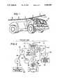
- FIG. 1is a perspective view of a mining vehicle according to the present invention.
- FIG. 2is a schematic diagram of the preferred vehicle power and drive system using a diesel engine for generating electric power as an auxiliary power source.
- FIG. 3is a schematic alternative vehicle power and drive system with a DC battery as an auxiliary power source.
- FIG. 4is a schematic alternative vehicle power and drive system using a diesel engine for providing mechanical power directly to the vehicle drive train.
- FIG. 1shows an electric mining vehicle 10 suitable for underground use.
- An articulated pantograph arm 12extends upward from the vehicle, acting as a power link to make electrical contact with an electrically conductive overhead trolley line 14.
- the trolley line 14is a curvilinear track defining the vehicle path.
- the linecarries AC power at either 50 or 60hZ from a remote source (not shown) and includes four conductors: three providing three phase AC power and one connected to ground. Each of these four conductors is electrically contacted by the pantograph arm 12.
- FIG. 2schematically illustrates a preferred embodiment of the vehicle drive system.
- a transfer switch 16selectively receives AC power from the pantograph arm 12 and from alternative on-board backup sources, as will be discussed below.
- the switch 16directs the AC power to various vehicle functions.
- a programmable logic controller (PLC) 18automatically controls the function of the transfer switch 16 in response to vehicle operating conditions or manual operator selections. When proper connection is made between the trolley line 14 and the pantograph arm 12, the PLC 18 allows the operator to energize the vehicle's primary drive system.
- PLCprogrammable logic controller
- the vehicle's primary drive systemincludes a commercially available pulse width modulated (PWM) AC motor speed controller 20, which varies the AC frequency of its output.
- PWMpulse width modulated
- the controller outputis controlled by the PLC 18, which receives its signal from an operator foot pedal (not shown).
- the motor controller 20is preferably enclosed in a dustproof protective housing (not shown) to prevent dust and damaging objects from impairing its function. While a conventional AC motor controller is large and bulky, it may be made more compact by using an alternative cooling system instead of conventional air cooling. For materials handling vehicle applications, the motor controller should be shock mounted to the vehicle to prevent damage from vibrations.
- a primary variable speed AC drive motor 24is connected to the AC output of the motor controller 20 and transmits power from an output shaft 25 through a vehicle gear box 26 portion of a mechanical transmission 27 to a set of ground-engaging wheels 28 for propelling the vehicle. With the motor directly coupled to the wheels, vehicle speed is directly proportional to motor speed. For typical hauling applications of an underground mining vehicle, the drive motor 24 might be rated at about 800 horsepower, although this may vary widely, depending on the application, hauling capacity and size of the vehicle.
- a set of separate variable speed AC wheel motorsmay be electrically connected to the motor controller 20 for separately driving each wheel 28.
- the output of each motoris directly connected to a corresponding wheel.
- This approachis appropriate for high powered vehicles, as four moderately sized motors may be more cost effective than one very large motor.
- the use of multiple wheel motorsalso eliminates the need for the mechanical transmission 27, including gear box 26.
- variable speed AC drive motorcould be used, instead of single motor 24, to drive each axle of the vehicle.
- the transfer switch 16also provides AC power through line 31 to an accessory three phase AC motor 32, which operates at a constant speed, and is mechanically connected through drive lines 33, 35, respectively, to drive a 24 volt direct current alternator 34 and a hydraulic pump 36.
- the alternator 34provides DC power to the vehicle's DC electrical system 38, while the hydraulic pump 36 pressurizes the vehicle's hydraulic system, including steering, dump mechanism and brakes.
- a prime mover such as a diesel engine 54 mounted on the vehicle 10provides an auxiliary or backup source of power for moving the vehicle when the pantograph arm 12 is disconnected from the trolley line, or when primary power is otherwise unavailable. This feature permits the vehicle to be shifted from one trolley line to another under its own power, and to maneuver where no trolley lines exist.
- the capacity of the auxiliary drive systemneed not be substantial, as the vehicle need only creep at a slow rate when disconnected from the trolley line 14.
- the diesel engine 54drives a three phase AC generator 56, which is electrically connected to provide AC power to the transfer switch 16.
- the transfer switch 16provides AC power through conductor 17 to the motor controller 20 and through conductor 21 to drive motor 24 for driving the vehicle, and through conductor 31 to accessory AC motor 32 for powering the hydraulic and DC electrical systems 36, 38.
- the operator's signalis transmitted through the programmable logic controller 18, which starts the diesel engine 54. Once the engine is running, the generator 56 is engaged, and stand-by power is available.
- the PLC 18then coordinates the disconnection from the trolley line 14 and connection of auxiliary power to the motor controller 20 and accessory motor 32. Control signals between the PLC and diesel engine are transmitted through line 19. Control signals between the PLC, PWM and transfer switch are transmitted through lines 13 and 15. The power transfer is made without interruption of vehicle performance, except for the reduction in vehicle speed due to the limited available power from the on-board source. To reconnect with the trolley line 14 from the auxiliary power source, a similar procedure is followed, with the PLC 18 controlling and monitoring all required functions.
- an electrical storage battery 42 mounted on the vehicleprovides backup power.
- the battery 42is electrically connected to an inverter 44, which converts direct current to alternating current.
- the inverter 44provides AC power to the transfer switch 16, which directs the power to the vehicle's primary drive system and to the accessory AC motor 32.
- the function of the inverter 44is controlled by the programmable logic controller 18.
- the battery 42is kept charged by a transformer 48 and charger 50, which are arranged to draw AC power from the pantograph arm 12 and to convert it to DC power for charging the battery 42.
- the batterymay be connected to a DC drive motor which is operably connected by a mechanical power transmission to the gear box 26.
- the vehiclemay thus be driven when the pantograph arm 12 is disconnected, and the need for the inverter 44 is eliminated, although a separate speed controller for the DC motor would be required.
- the output from diesel engine 54may be connected through a secondary mechanical transmission 60 directly to the gear box 26 for powering the vehicle when the pantograph arm 12 is disconnected from the trolley line 14 or when the primary source of AC power is otherwise unavailable.
- the mining vehiclemight employ a primary AC motor 24 rated at 560kW or about 800 horsepower.
- a suitable modelis the type HXR355LC4B5E available from Atlas Copco of Sweden.
- a suitable transfer switch 16is available as Part No. ATSBM31000-KJ from Westinghouse Electrical Components Division, London, Kentucky.
- the motor controller 20is a custom design adapted for the mining environment having the features previously described.
- a suitable electrical equivalentshould be rated for 1400 amperes, such as Part No. 1352-BMC from Allen Bradley/Stromberg of Brown Deer, Wisconsin.
- a suitable programmable logic controller 18is also available from Allen Bradley as PLC 5/25, with multiple discrete and analogue inputs and outputs.
- a suitable auxiliary diesel engine 54is the F12L413F Deutz engine with the associated generator 56 being a Lima generator Part No. 431RSS2557.
- the vehicleWhen not in use, the vehicle is parked in a maintenance area or underground shop.
- the vehicleis brought into service on auxiliary power to creep over to an overhead trolley line, typically a two-minute run.
- the pantograph armis hooked up to the trolley line and the vehicle is run on external power down to a loading zone several hundred to several thousand meters away, a run of about 20 to 30 minutes.
- the loading zoneis typically removed from the main power line to prevent damage to the line during loading, and to avoid electrical safety hazards.
- the vehiclethen creeps on its auxiliary power to the loading zone and is loaded. Loading typically takes about two minutes. Once loaded, the vehicle creeps back to the trolley line, hooks up and travels as far as possible toward the unloading area, typically a 30-minute run. The vehicle then unhooks from the trolley line and creeps to the unloading area on auxiliary power. Unloading takes about five minutes, after which the vehicle creeps back to the trolley line, hooks up and repeats the cycle.
- the vehicleAt the end of a shift, the vehicle returns to the point on the trolley line nearest the maintenance area, unhooks and creeps to a parking space in the maintenance area.
Landscapes
- Engineering & Computer Science (AREA)
- Mechanical Engineering (AREA)
- Transportation (AREA)
- Power Engineering (AREA)
- Sustainable Development (AREA)
- Life Sciences & Earth Sciences (AREA)
- Sustainable Energy (AREA)
- Chemical & Material Sciences (AREA)
- Combustion & Propulsion (AREA)
- Electric Propulsion And Braking For Vehicles (AREA)
- Control Of Eletrric Generators (AREA)
- Control Of Ac Motors In General (AREA)
- Hybrid Electric Vehicles (AREA)
Abstract
Description
This invention relates to electric vehicles and more particularly to such vehicles powered from an external source of electricity.
Externally powered electric vehicles are commonly used in many industries, particularly the mining industry, in which safety requirements prevent or restrict the underground use of internal combustion engine-powered vehicles. Such electric vehicles typically draw power from an external trolley line or trailing umbilical cord that supplies alternating current (AC). Trolley lines are typically employed by hauling trucks; umbilical lines are generally used by scoop vehicles. The alternating current may be used to power an AC motor or may be rectified to power a direct current (DC) powered motor.
Existing vehicles using AC motors have had several disadvantages relating to their controllability. Previously existing AC controllers were unavailable or unsuitable for use on mobile vehicles due to their size, complexity, and environmental sensitivity, particularly to acceleration and mechanical shock. As a result, such systems have been used only for monorail-type storage and retrieval systems having limited mobility within a restricted track such as along a single aisle in an automated warehouse. In such systems, the controller is not transported on the car, and the environment is easily controlled.
At low speeds, AC motors are susceptible to "cogging," which impairs smooth operation. AC motors have been employed in electric vehicles, but these have been constant speed motors. Thus, they require a complex transmission and a clutch slipping technique employed by skilled operators to drive the vehicle at a variable speed.
DC motors, on the other hand, are easily controllable. However, as a practical matter they require an inefficient conversion of AC power to DC. Such an AC to DC conversion system is shown, for example, in U.S. Pat. No. 4,483,148 to Minami.
In addition, DC motors are more complex than AC motors, with brushes that are prone to wear. As a result, they are more expensive to maintain and less reliable than AC motors. The trolley line approach is also unsuitable for providing DC power from an external source, due to power loss through line resistance, particularly on long lines. Some prior art systems employ both AC and DC motors to gain the advantages of each system. However, this comes at the cost of added complexity and redundancy. U.S. Pat. No. 4,099,589 to Williams, for example, shows an electric car with AC and DC drive motors. The car may be driven by the DC motor alone during short range stop-and-go driving where controllability is important, and may be driven by the AC motor alone during relatively constant speed long range driving when efficiency is critical. The use of redundant motors, however, substantially increases cost, and both motors rely on an on-board internal combustion engine for electric power generation.
The primary objects of the invention are to provide:
1. an electric drive vehicle driven by a variable speed AC electric drive motor that operates smoothly and efficiently at all vehicle speeds;
2. a vehicle as aforesaid that can be supplied with external electric power from a trolley line;
3. a vehicle as aforesaid that includes an on-board auxiliary power source;
4. a vehicle as aforesaid in which an auxiliary on-board power source includes an on-board means for supplying backup AC electric power to the variable speed AC drive motor; and
5. a vehicle as aforesaid which includes on-board means to differentiate and switch between trolley and on-board auxiliary power.
According to the present invention, the primary objects are achieved by providing an electric vehicle having an AC motor as its primary driver while the vehicle is connected to a trolley line. The AC motor is connected to an on-board variable speed controller and, in preferred embodiments, is switchable to an auxiliary on-board AC power source when the vehicle is disconnected from the trolley line.
The auxiliary power source preferably includes an on-board internal combustion engine for generating AC power to drive the primary AC drive motor, or for providing mechanical power directly to the vehicle drive train. Alternatively, the auxiliary power source may include an on-board DC battery connected to an inverter for providing AC power to the primary AC drive motor, or connected to a DC motor for directly driving the vehicle.
The foregoing and additional features and advantages of the present invention will be more readily apparent from the following detailed description which proceeds with reference to the accompanying drawings.
FIG. 1 is a perspective view of a mining vehicle according to the present invention.
FIG. 2 is a schematic diagram of the preferred vehicle power and drive system using a diesel engine for generating electric power as an auxiliary power source.
FIG. 3 is a schematic alternative vehicle power and drive system with a DC battery as an auxiliary power source.
FIG. 4 is a schematic alternative vehicle power and drive system using a diesel engine for providing mechanical power directly to the vehicle drive train.
FIG. 1 shows anelectric mining vehicle 10 suitable for underground use. An articulatedpantograph arm 12 extends upward from the vehicle, acting as a power link to make electrical contact with an electrically conductiveoverhead trolley line 14. Thetrolley line 14 is a curvilinear track defining the vehicle path. The line carries AC power at either 50 or 60hZ from a remote source (not shown) and includes four conductors: three providing three phase AC power and one connected to ground. Each of these four conductors is electrically contacted by thepantograph arm 12.
FIG. 2 schematically illustrates a preferred embodiment of the vehicle drive system. Atransfer switch 16 selectively receives AC power from thepantograph arm 12 and from alternative on-board backup sources, as will be discussed below. Theswitch 16 directs the AC power to various vehicle functions. A programmable logic controller (PLC) 18 automatically controls the function of thetransfer switch 16 in response to vehicle operating conditions or manual operator selections. When proper connection is made between thetrolley line 14 and thepantograph arm 12, thePLC 18 allows the operator to energize the vehicle's primary drive system.
The vehicle's primary drive system includes a commercially available pulse width modulated (PWM) ACmotor speed controller 20, which varies the AC frequency of its output. The controller output is controlled by thePLC 18, which receives its signal from an operator foot pedal (not shown). Themotor controller 20 is preferably enclosed in a dustproof protective housing (not shown) to prevent dust and damaging objects from impairing its function. While a conventional AC motor controller is large and bulky, it may be made more compact by using an alternative cooling system instead of conventional air cooling. For materials handling vehicle applications, the motor controller should be shock mounted to the vehicle to prevent damage from vibrations.
A primary variable speedAC drive motor 24 is connected to the AC output of themotor controller 20 and transmits power from anoutput shaft 25 through avehicle gear box 26 portion of amechanical transmission 27 to a set of ground-engagingwheels 28 for propelling the vehicle. With the motor directly coupled to the wheels, vehicle speed is directly proportional to motor speed. For typical hauling applications of an underground mining vehicle, thedrive motor 24 might be rated at about 800 horsepower, although this may vary widely, depending on the application, hauling capacity and size of the vehicle.
As an alternative to a single AC drive motor coupled to a mechanical transmission, a set of separate variable speed AC wheel motors (not shown) may be electrically connected to themotor controller 20 for separately driving eachwheel 28. In such embodiment, the output of each motor is directly connected to a corresponding wheel. This approach is appropriate for high powered vehicles, as four moderately sized motors may be more cost effective than one very large motor. The use of multiple wheel motors also eliminates the need for themechanical transmission 27, includinggear box 26.
According to still another alternative embodiment (not shown) a separate variable speed AC drive motor could be used, instead ofsingle motor 24, to drive each axle of the vehicle.
Thetransfer switch 16 also provides AC power throughline 31 to an accessory threephase AC motor 32, which operates at a constant speed, and is mechanically connected throughdrive lines current alternator 34 and ahydraulic pump 36. Thealternator 34 provides DC power to the vehicle's DCelectrical system 38, while thehydraulic pump 36 pressurizes the vehicle's hydraulic system, including steering, dump mechanism and brakes.
A prime mover such as adiesel engine 54 mounted on thevehicle 10 provides an auxiliary or backup source of power for moving the vehicle when thepantograph arm 12 is disconnected from the trolley line, or when primary power is otherwise unavailable. This feature permits the vehicle to be shifted from one trolley line to another under its own power, and to maneuver where no trolley lines exist. The capacity of the auxiliary drive system need not be substantial, as the vehicle need only creep at a slow rate when disconnected from thetrolley line 14.
Thediesel engine 54 drives a threephase AC generator 56, which is electrically connected to provide AC power to thetransfer switch 16. Thetransfer switch 16 provides AC power throughconductor 17 to themotor controller 20 and throughconductor 21 to drivemotor 24 for driving the vehicle, and throughconductor 31 toaccessory AC motor 32 for powering the hydraulic and DCelectrical systems
When auxiliary power is required, the operator's signal is transmitted through theprogrammable logic controller 18, which starts thediesel engine 54. Once the engine is running, thegenerator 56 is engaged, and stand-by power is available. ThePLC 18 then coordinates the disconnection from thetrolley line 14 and connection of auxiliary power to themotor controller 20 andaccessory motor 32. Control signals between the PLC and diesel engine are transmitted throughline 19. Control signals between the PLC, PWM and transfer switch are transmitted throughlines trolley line 14 from the auxiliary power source, a similar procedure is followed, with thePLC 18 controlling and monitoring all required functions.
In the alternative embodiment shown in FIG. 3, anelectrical storage battery 42 mounted on the vehicle provides backup power. Thebattery 42 is electrically connected to aninverter 44, which converts direct current to alternating current. Theinverter 44 provides AC power to thetransfer switch 16, which directs the power to the vehicle's primary drive system and to theaccessory AC motor 32. The function of theinverter 44 is controlled by theprogrammable logic controller 18. Thebattery 42 is kept charged by atransformer 48 andcharger 50, which are arranged to draw AC power from thepantograph arm 12 and to convert it to DC power for charging thebattery 42.
In an alternative embodiment not shown, the battery may be connected to a DC drive motor which is operably connected by a mechanical power transmission to thegear box 26. The vehicle may thus be driven when thepantograph arm 12 is disconnected, and the need for theinverter 44 is eliminated, although a separate speed controller for the DC motor would be required.
In an alternative embodiment shown in FIG. 4, the output fromdiesel engine 54 may be connected through a secondarymechanical transmission 60 directly to thegear box 26 for powering the vehicle when thepantograph arm 12 is disconnected from thetrolley line 14 or when the primary source of AC power is otherwise unavailable.
In the preferred embodiment, the mining vehicle might employ aprimary AC motor 24 rated at 560kW or about 800 horsepower. A suitable model is the type HXR355LC4B5E available from Atlas Copco of Sweden. Asuitable transfer switch 16 is available as Part No. ATSBM31000-KJ from Westinghouse Electrical Components Division, London, Kentucky.
Themotor controller 20 is a custom design adapted for the mining environment having the features previously described. A suitable electrical equivalent should be rated for 1400 amperes, such as Part No. 1352-BMC from Allen Bradley/Stromberg of Brown Deer, Wisconsin. A suitableprogrammable logic controller 18 is also available from Allen Bradley as PLC 5/25, with multiple discrete and analogue inputs and outputs. A suitableauxiliary diesel engine 54 is the F12L413F Deutz engine with the associatedgenerator 56 being a Lima generator Part No. 431RSS2557.
While all mining operations vary, the following is a representative duty cycle for the vehicle of the preferred embodiment.
When not in use, the vehicle is parked in a maintenance area or underground shop. The vehicle is brought into service on auxiliary power to creep over to an overhead trolley line, typically a two-minute run. The pantograph arm is hooked up to the trolley line and the vehicle is run on external power down to a loading zone several hundred to several thousand meters away, a run of about 20 to 30 minutes. The loading zone is typically removed from the main power line to prevent damage to the line during loading, and to avoid electrical safety hazards.
The vehicle then creeps on its auxiliary power to the loading zone and is loaded. Loading typically takes about two minutes. Once loaded, the vehicle creeps back to the trolley line, hooks up and travels as far as possible toward the unloading area, typically a 30-minute run. The vehicle then unhooks from the trolley line and creeps to the unloading area on auxiliary power. Unloading takes about five minutes, after which the vehicle creeps back to the trolley line, hooks up and repeats the cycle.
At the end of a shift, the vehicle returns to the point on the trolley line nearest the maintenance area, unhooks and creeps to a parking space in the maintenance area.
Having illustrated and described the principles of my invention by what is presently a preferred embodiment and several suggested alternatives, it should be apparent to those skilled in the art that the illustrated embodiment may be modified without departing from such principles.
Claims (38)
1. A self-propelled vehicle comprising:
a driven ground-engaging means for forcibly acting on the ground to propel the vehicle;
a variable speed AC drive motor on the vehicle drivingly connected to the ground engaging means;
a motor controller having a variable frequency AC output connected to the drive motor;
a switch on the vehicle having first and second inputs, and a switch output connected to the motor controller, the switch having a first position in which the first input is connected to the switch output while the second input is disconnected from the switch output, the switch having a second position in which the second input is connected to the switch output while the first input is disconnected from the switch output;
an electrical conductor for engaging an external power source and for transmitting AC power from the external source to the first input;
an on-board source of AC power mounted on the vehicle and connected to the second input on the switch to provide power to the switch; and
a switch controller operably connected to the switch and the on-board source, the switch controller being operable in response to a control signal to activate the on-board source, and thereafter to shift the switch from the first position to the second position.
2. The vehicle of claim 1 wherein the on-board source includes an internal combustion engine.
3. The vehicle of claim 1 wherein the switch controller includes a sensor for detecting the AC electric output from the on-board source whereby the switch controller may synchronize the on-board power output with the external power.
4. The vehicle of claim 1 including an on-board AC accessory motor connected to the switch output.
5. The vehicle of claim 4 including a hydraulic pump connected to the accessory motor.
6. The vehicle of claim 1 wherein the switch controller includes means for shifting the switch to its second position in response to disengagement of the conductor from the external power source.
7. The vehicle of claim 1 wherein the switch controller includes means for shifting the switch in response to availability of power from the on-board source.
8. The vehicle of claim 1 wherein the electrical conductor includes means for connecting to a trolley line.
9. A self-propelled vehicle having a traction device contacting the ground to propel the vehicle, the vehicle comprising;
an AC drive motor on the vehicle;
a power transmission operably connected to the motor and to the traction device for transmitting power to the traction device;
an electrical conductor mounted on the vehicle and connectable to an external power source;
an on-board source of power mounted on the vehicle;
a switch on the vehicle having a first position in which the conductor is electrically connected to the motor and the on-board source is disconnected from the motor, the switch having a second position in which the on-board source is connected to the motor and the conductor is disconnected from the motor;
a switch controller operably connected to the switch and to the on-board source, the switch controller being operable in response to a control signal to activate the on-board source, and thereafter to shift the switch from the first position to the second position; and
a motor controller connected between the switch and the motor and having a variable frequency AC output.
10. The vehicle of claim 9 wherein the on-board source includes an internal combustion engine.
11. The vehicle of claim 9 wherein the on-board source includes means for generating an AC electric output.
12. The vehicle of claim 11 wherein the switch controller includes a sensor for detecting the AC electric output from the on-board source.
13. The vehicle of claim 11 wherein the switch controller includes means for adjusting the AC electric output on the on-board source.
14. The vehicle of claim 11 wherein the switch controller includes means for adjusting the frequency of the AC electric output of the on-board source.
15. The vehicle of claim 9 including an on-board second motor connected to the switch output.
16. The vehicle of claim 15 including a hydraulic pump connected to the second motor.
17. The vehicle of claim 9 wherein the switch controller includes means for shifting the switch in response to disengagement of the connector from the external power source.
18. The vehicle of claim 9 wherein the controller includes means for shifting the switch in response to availability of power from the on-board source.
19. The vehicle of claim 9 wherein the electrical conductor includes means for connecting to a trolley line.
20. A method of operating an electric vehicle having a variable speed AC drive motor, an on-board source of AC power, and a conductor attachable to an external AC power source, the method comprising the steps:
operating the vehicle with power drawn from the external source through the conductor;
sensing a transfer signal;
in response to the signal, activating the on-board source of power;
sensing the external AC power and the on-board AC power;
adjusting the on-board source to synchronize the on-board source with the external source; and
after synchronizing, switching to operation of the vehicle with power from the on-board source.
21. The method of claim 20 including the step of disconnecting the conductor from the external source.
22. The method of claim 20 wherein the step of synchronizing includes adjusting the AC frequency of the on-board source.
23. The method of claim 20 wherein the step of synchronizing includes adjusting the AC phase of the on-board source.
24. The vehicle of claim 9 including a manually operated control signal generator for generating said control signal.
25. A self-propelled vehicle having a traction device contacting the ground to propel the vehicle, the vehicle comprising:
an AC drive motor on the vehicle;
a power transmission operably connected to the motor and to the traction device for transmitting power to the traction device;
an electrical conductor mounted on the vehicle and connectable to an external power source;
a switch on the vehicle having a first position in which the conductor is electrically connected to the motor and the on-board source is disconnected from the motor, the switch having a second position in which the on-board source is connected to the motor and the conductor is disconnected from the motor;
a switch controller operably connected to the switch and to the on-board source, the switch controller being operable in response to a control signal to activate the on-board source, and thereafter to shift the switch from the first position to the second position; and
a motor speed controller connected between the switch and the motor and having a variable frequency AC output, the motor speed controller being operably connected to the switch controller such that the switch controller controls said AC output from the motor controller to the motor.
26. The vehicle of claim 25 wherein the on-board source includes an internal combustion engine.
27. The vehicle of claim 25 wherein the on-board source includes means for generating an AC electric output.
28. The vehicle of claim 27 wherein the controller includes a sensor for detecting the AC electric output from the on-board source.
29. The vehicle of claim 27 wherein the controller includes means for adjusting the AC electric output of the on-board source.
30. The vehicle of claim 27 wherein the controller includes means for adjusting the frequency of the AC electric output of the on-board source.
31. The vehicle of claim 25 including an on-board second motor connected to the switch output.
32. The vehicle of claim 31 including a hydraulic pump connected to the second motor.
33. The vehicle of claim 25 wherein the controller includes means for shifting the switch in response to disengagement of the conductor from the external power source.
34. The vehicle of claim 25 wherein the controller includes means for shifting the switch in response to availability of power from the on-board source.
35. The vehicle of claim 25 wherein the electrical conductor includes means for connecting to a trolley line.
36. The vehicle of claim 25 including a manually operated control signal generator for generating said control signal.
37. A self-propelled vehicle having a traction device contracting the ground to propel the vehicle, the vehicle comprising:
an AC drive motor on the vehicle;
a power transmission operably connected to the motor and to the traction device for transmitting power to the traction device;
an electrical conductor mounted on the vehicle and connectable to an external power source;
an on-board source of power mounted on the vehicle;
a switch on the vehicle having a first position in which the conductor is electrically connected to the motor and the on-board source is disconnected from the motor, the switch having a second position in which the on-board source is connected to the motor and the conductor is disconnected from the motor;
first control means for providing variable frequency AC power to the motor; and
second control means for automatically, in response to a control signal, activating the on-board source, thereafter shifting the switch from the first position to the second position, and for providing a control signal to the first control means.
38. The vehicle of claim 35 wherein the first control means includes only a single controller operably connected to the switch and to the motor.
Priority Applications (10)
| Application Number | Priority Date | Filing Date | Title |
|---|---|---|---|
| US07/753,719US5293947A (en) | 1991-09-03 | 1991-09-03 | Variable speed AC electric drive vehicle |
| RU9494018703ARU2100221C1 (en) | 1991-09-03 | 1992-09-03 | Vehicle |
| PCT/US1992/007443WO1993004887A1 (en) | 1991-09-03 | 1992-09-03 | Variable speed ac electric drive vehicle |
| JP5505396AJPH06510418A (en) | 1991-09-03 | 1992-09-03 | variable speed ac electric drive vehicle |
| PL92302614APL169771B1 (en) | 1991-09-03 | 1992-09-03 | Electric vehicle powered by alternating current PL |
| FI941000AFI941000L (en) | 1991-09-03 | 1992-09-03 | Variable speed AC electric drive vehicle |
| CA002116585ACA2116585C (en) | 1991-09-03 | 1992-09-03 | Variable speed ac electric drive vehicle |
| AU26539/92AAU662355B2 (en) | 1991-09-03 | 1992-09-03 | Variable speed AC electric drive vehicle |
| EP92920661AEP0602186A1 (en) | 1991-09-03 | 1992-09-03 | Variable speed ac electric drive vehicle |
| CN92112485ACN1085169A (en) | 1991-09-03 | 1992-09-30 | Variable speed AC drive vehicles |
Applications Claiming Priority (1)
| Application Number | Priority Date | Filing Date | Title |
|---|---|---|---|
| US07/753,719US5293947A (en) | 1991-09-03 | 1991-09-03 | Variable speed AC electric drive vehicle |
Publications (1)
| Publication Number | Publication Date |
|---|---|
| US5293947Atrue US5293947A (en) | 1994-03-15 |
Family
ID=25031845
Family Applications (1)
| Application Number | Title | Priority Date | Filing Date |
|---|---|---|---|
| US07/753,719Expired - Fee RelatedUS5293947A (en) | 1991-09-03 | 1991-09-03 | Variable speed AC electric drive vehicle |
Country Status (10)
| Country | Link |
|---|---|
| US (1) | US5293947A (en) |
| EP (1) | EP0602186A1 (en) |
| JP (1) | JPH06510418A (en) |
| CN (1) | CN1085169A (en) |
| AU (1) | AU662355B2 (en) |
| CA (1) | CA2116585C (en) |
| FI (1) | FI941000L (en) |
| PL (1) | PL169771B1 (en) |
| RU (1) | RU2100221C1 (en) |
| WO (1) | WO1993004887A1 (en) |
Cited By (74)
| Publication number | Priority date | Publication date | Assignee | Title |
|---|---|---|---|---|
| FR2799701A1 (en)* | 1999-10-19 | 2001-04-20 | Giovanni Tonarelli | Motorway lane, with overhead electrification to power hybrid trucks and buses, uses railway-style overhead electric lines with pantographs fitted to heavy vehicles that have a supplementary electric drive |
| US20050116669A1 (en)* | 2002-02-07 | 2005-06-02 | Elin Ebg Traction Gmbh | Vehicle comprising a battery drive and a method for operating a vehicle of this type |
| US20080021602A1 (en)* | 2006-05-24 | 2008-01-24 | Ise Corporation | Electrically Powered Rail Propulsion Vehicle and Method |
| US20080122393A1 (en)* | 2005-05-26 | 2008-05-29 | Mitsubishi Electric Corporation | Controller For Variable Speed Alternating Current Motor |
| US20100004807A1 (en)* | 2008-07-06 | 2010-01-07 | Paul H Kydd | Control system for electric hybrid vehicle conversion |
| US20100207560A1 (en)* | 2007-09-21 | 2010-08-19 | Mitsubishi Electric Corporation | Power conversion apparatus for electric vehicle |
| US20100282557A1 (en)* | 2006-09-18 | 2010-11-11 | Qinfen He | Mains power supply equipment for rubber-tired port container gantry cranes |
| US20100299008A1 (en)* | 2007-09-10 | 2010-11-25 | Toyota Jidosha Kabushiki Kaisha | Apparatus and method for activating system of vehicle |
| WO2011049687A1 (en)* | 2009-10-23 | 2011-04-28 | Siemens Industry, Inc. | Peak demand reduction in mining haul trucks utilizing an on-board energy storage system |
| US20110155487A1 (en)* | 2008-06-13 | 2011-06-30 | Cargotec Finland Oy | Electrically driven straddle carrier, terminal tractor or corresponding |
| WO2011080392A1 (en) | 2009-12-28 | 2011-07-07 | Sandvik Mining And Construction Oy | Mining vehicle and method for its energy supply |
| WO2011080393A1 (en) | 2009-12-28 | 2011-07-07 | Sandvik Mining And Construction Oy | Mining vehicle and method for its energy supply |
| WO2011109050A3 (en)* | 2010-03-04 | 2012-03-01 | General Electric Company | Electric drive vehicle, system and method |
| CN102381202A (en)* | 2011-08-17 | 2012-03-21 | 中国北车股份有限公司大连电力牵引研发中心 | Urban rail vehicle power supply system and urban rail vehicle |
| US20130048382A1 (en)* | 2011-08-24 | 2013-02-28 | Stephen A. Rudinec | All Electric Powered Mobile Jumbo Drill Machine |
| WO2013081869A1 (en)* | 2011-12-01 | 2013-06-06 | Caterpillar Inc. | Control strategy for powering auxiliary device in trolley capable mining truck |
| WO2013081871A1 (en)* | 2011-12-01 | 2013-06-06 | Caterpillar Inc. | Control strategy for providing regenerative electrical power to trolley line in trolley capable mining truck |
| US20130146411A1 (en)* | 2011-12-08 | 2013-06-13 | Caterpillar Inc. | Method and apparatus to eliminate fuel use for electric drive machines during trolley operation |
| US20130220714A1 (en)* | 2012-02-23 | 2013-08-29 | Stephen A. Rudinec | All-electric powered anfo vehicle |
| US20130261868A1 (en)* | 2012-03-30 | 2013-10-03 | Caterpillar, Inc. | Laser Sensors For Trolley Guidance Signal |
| US20130261901A1 (en)* | 2012-03-30 | 2013-10-03 | Caterpillar, Inc. | Display Conveying Trolley Position to Operator |
| US20130264163A1 (en)* | 2012-04-10 | 2013-10-10 | Caterpillar Inc. | Pantograph mounting structure |
| US20140041951A1 (en)* | 2011-05-10 | 2014-02-13 | Komatsu Ltd. | Transport vehicle equipped with current collector |
| WO2014083239A1 (en)* | 2012-11-28 | 2014-06-05 | Sandvik Mining And Construction Oy | A method and an arrangement for controlling power supply in an electric mining unit |
| WO2014112926A1 (en) | 2013-01-18 | 2014-07-24 | Enega AB | Device and method for effecting electric drive of heavy trucks |
| US8818593B2 (en) | 2012-04-22 | 2014-08-26 | Caterpillar Inc. | Trolley driven machine record and playback automation |
| US8874294B2 (en) | 2012-06-04 | 2014-10-28 | Caterpillar Inc. | Simplified topology for trolley assist-capable electric drive truck |
| EP2810809A1 (en) | 2013-06-07 | 2014-12-10 | Sandvik Mining and Construction Oy | Mining vehicle and method for its energy supply |
| US20150002056A1 (en)* | 2008-08-14 | 2015-01-01 | General Electric Company | Vehicle, system and method |
| CN104340568A (en)* | 2013-07-25 | 2015-02-11 | 芜湖爱瑞特环保科技有限公司 | A heavy-duty garbage transport vehicle using an AC controller |
| EP2842213A1 (en) | 2012-04-23 | 2015-03-04 | Brokk AB | A portable power supply system for an electrically driven work machine and a work machine equipped with such a power supply system |
| WO2015048422A1 (en)* | 2013-09-27 | 2015-04-02 | Siemens Industry, Inc. | System and method for all electrical operation of a mining haul truck |
| EP2857253A1 (en) | 2013-10-02 | 2015-04-08 | Sandvik Mining and Construction Oy | Mining vehicle and method for its energy supply |
| US20160052528A1 (en)* | 2013-04-12 | 2016-02-25 | System7-Railsupport Gmbh | Device for conveying material during track laying |
| US9315107B2 (en) | 2011-05-10 | 2016-04-19 | Komatsu Ltd. | Transport vehicle equipped with current collector |
| US9321364B1 (en) | 2015-06-30 | 2016-04-26 | Proterra Inc. | Heated charging interface of electric vehicle |
| US9550426B2 (en)* | 2012-02-27 | 2017-01-24 | Schunk Bahn- Und Industrietechnik Gmbh | Current transmission device for charging electrical energy stores of vehicles at overhead charging stations |
| EP2635477A4 (en)* | 2010-11-02 | 2018-01-10 | Transport Energy Systems Pty Ltd | Ac drive system for a vehicle |
| US9994117B2 (en)* | 2016-04-20 | 2018-06-12 | Artisan Vehicle Systems Inc. | System and method for providing power to a mining operation |
| WO2018115403A1 (en)* | 2016-12-22 | 2018-06-28 | Abb Schweiz Ag | Hybrid drive system for a traction vehicle |
| ES2677073A1 (en)* | 2017-01-27 | 2018-07-27 | Salvador AYATS SERRAT | Land vehicle (Machine-translation by Google Translate, not legally binding) |
| US20180345822A1 (en)* | 2014-08-19 | 2018-12-06 | Jilin University | Electrified railway power grid system without negative sequence in whole process and without power supply networks at intervals |
| US10270265B2 (en) | 2014-03-26 | 2019-04-23 | New Fryer Industries Canada ULC | Controlling batteries for electric bus |
| US10352165B2 (en)* | 2013-09-30 | 2019-07-16 | Komatsu Ltd. | Mine mining system |
| US10377251B2 (en) | 2015-03-26 | 2019-08-13 | Proterra Inc. | Electric vehicle charging interface |
| US20190267832A1 (en)* | 2016-11-24 | 2019-08-29 | Normet Oy | Method and arrangement for actuating power pack |
| GB2578484A (en)* | 2018-10-29 | 2020-05-13 | Mastenbroek Ltd | Trenching apparatus and a method of trenching |
| WO2020206293A1 (en) | 2019-04-03 | 2020-10-08 | Artisan Vehicle Systems, Inc. | Interchangeable energy device for electric vehicle |
| US20220063423A1 (en)* | 2018-12-14 | 2022-03-03 | Volvo Truck Corporation | An electric power transmission system for a vehicle |
| US11434737B2 (en) | 2017-12-05 | 2022-09-06 | U.S. Well Services, LLC | High horsepower pumping configuration for an electric hydraulic fracturing system |
| US11449018B2 (en) | 2012-11-16 | 2022-09-20 | U.S. Well Services, LLC | System and method for parallel power and blackout protection for electric powered hydraulic fracturing |
| US11451016B2 (en) | 2012-11-16 | 2022-09-20 | U.S. Well Services, LLC | Switchgear load sharing for oil field equipment |
| US11454079B2 (en) | 2018-09-14 | 2022-09-27 | U.S. Well Services Llc | Riser assist for wellsites |
| US11454170B2 (en) | 2012-11-16 | 2022-09-27 | U.S. Well Services, LLC | Turbine chilling for oil field power generation |
| US11459863B2 (en) | 2019-10-03 | 2022-10-04 | U.S. Well Services, LLC | Electric powered hydraulic fracturing pump system with single electric powered multi-plunger fracturing pump |
| US11476781B2 (en) | 2012-11-16 | 2022-10-18 | U.S. Well Services, LLC | Wireline power supply during electric powered fracturing operations |
| US11506126B2 (en) | 2019-06-10 | 2022-11-22 | U.S. Well Services, LLC | Integrated fuel gas heater for mobile fuel conditioning equipment |
| US11578577B2 (en) | 2019-03-20 | 2023-02-14 | U.S. Well Services, LLC | Oversized switchgear trailer for electric hydraulic fracturing |
| US11674352B2 (en) | 2012-11-16 | 2023-06-13 | U.S. Well Services, LLC | Slide out pump stand for hydraulic fracturing equipment |
| US11713661B2 (en) | 2012-11-16 | 2023-08-01 | U.S. Well Services, LLC | Electric powered pump down |
| US11728709B2 (en) | 2019-05-13 | 2023-08-15 | U.S. Well Services, LLC | Encoderless vector control for VFD in hydraulic fracturing applications |
| US11850563B2 (en) | 2012-11-16 | 2023-12-26 | U.S. Well Services, LLC | Independent control of auger and hopper assembly in electric blender system |
| WO2024010498A1 (en)* | 2022-07-04 | 2024-01-11 | Epiroc Rock Drills Aktiebolag | Dynamic power allocation for mining machines |
| US11959533B2 (en) | 2017-12-05 | 2024-04-16 | U.S. Well Services Holdings, Llc | Multi-plunger pumps and associated drive systems |
| US12078110B2 (en) | 2015-11-20 | 2024-09-03 | Us Well Services, Llc | System for gas compression on electric hydraulic fracturing fleets |
| US12092095B2 (en) | 2016-12-02 | 2024-09-17 | Us Well Services, Llc | Constant voltage power distribution system for use with an electric hydraulic fracturing system |
| US12116875B2 (en) | 2018-10-09 | 2024-10-15 | U.S. Well Services, LLC | Electric powered hydraulic fracturing pump system with single electric powered multi-plunger pump fracturing trailers, filtration units, and slide out platform |
| US12142928B2 (en) | 2018-06-15 | 2024-11-12 | U.S. Well Services, LLC | Integrated mobile power unit for hydraulic fracturing |
| US12152711B2 (en) | 2019-12-27 | 2024-11-26 | U.S. Well Services, LLC | System and method for integrated flow supply line |
| US12221872B2 (en) | 2014-10-14 | 2025-02-11 | U.S. Well Services, LLC | System and method for parallel power and blackout protection for electric powered hydraulic fracturing |
| US12241353B2 (en) | 2019-12-31 | 2025-03-04 | U.S. Well Services, LLC | Self-regulating frac pump suction stabilizer/dampener |
| US12359548B2 (en) | 2019-12-30 | 2025-07-15 | U.S. Well Services, LLC | Electric motor driven transportation mechanisms for fracturing blenders |
| SE547494C2 (en)* | 2016-09-29 | 2025-10-07 | Brokk Ab | Demolition and demolition robot with a power supply system for an electric motor driving a hydraulic pump |
| US12444245B2 (en) | 2021-08-05 | 2025-10-14 | Hitachi Construction Machinery Co., Ltd. | Mine management system |
Families Citing this family (22)
| Publication number | Priority date | Publication date | Assignee | Title |
|---|---|---|---|---|
| DE9419568U1 (en)* | 1994-12-07 | 1995-03-16 | Rosenau, Viktor, Dipl.-Ing. (FH), 76185 Karlsruhe | Floor conveyor system with energy storage vehicles |
| DE29607651U1 (en)* | 1996-04-26 | 1997-08-28 | Kässbohrer Geländefahrzeug AG, 89250 Senden | Tracked vehicle |
| FR2783768B1 (en)* | 1998-09-28 | 2000-11-24 | Renault | CONTROL METHOD FOR A HYBRID VEHICLE WITH SERIAL ELECTRIC TRANSMISSION |
| BR9916406A (en)* | 1998-12-21 | 2001-09-25 | Siemens Energy & Automat | System, method and apparatus for connecting electrical forces in series under full load |
| PE20010833A1 (en)* | 1999-12-20 | 2001-09-08 | Siemens Energy And Automation Inc | SYSTEM, PROCEDURE AND APPARATUS FOR CONNECTING ELECTRICAL SOURCES IN SERIES UNDER FULL LOAD |
| FR2891961B1 (en)* | 2005-10-07 | 2008-03-14 | Alstom Transport Sa | METHOD OF MAINTAINING A VOLTAGE CONTINUOUS TO THE INPUT OF A CONTINUOUS-VOLTAGE ALTERNATIVE CONVERTER, RECORDING MEDIUM FOR THIS METHOD AND ELECTRIC VEHICLE |
| JP4218671B2 (en)* | 2005-10-13 | 2009-02-04 | トヨタ自動車株式会社 | Hybrid vehicle power output device |
| FI121769B2 (en)* | 2008-11-26 | 2025-05-06 | Sandvik Mining & Construction Oy | Procedure for using mining vehicles, mine arrangements and rock drilling rigs |
| FR2949098A1 (en)* | 2009-08-13 | 2011-02-18 | Roger Norbert Margreve | Double electric power absorbing system for permanent supply of power to e.g. electric traction/propulsion motor of car, has road electric power absorbing device mounted under road vehicle to assure contact with bar integrated to road |
| KR101175358B1 (en)* | 2009-10-16 | 2012-08-20 | 한국과학기술원 | Power supply system for non contact electromagnetic inductive charging of Electric Vehicle |
| KR101197317B1 (en)* | 2009-10-16 | 2012-11-05 | 한국과학기술원 | Device and method for dynamic configuration of electric power path in electric vehicle |
| US20120212047A1 (en)* | 2009-10-27 | 2012-08-23 | Masataka Sasaki | Electric drive vehicle |
| US20130126251A1 (en)* | 2011-11-18 | 2013-05-23 | Caterpillar, Inc. | Power System Control Strategy For Mining Truck |
| JP5839697B2 (en)* | 2012-04-26 | 2016-01-06 | 日立建機株式会社 | Operation management system |
| RU2543532C2 (en)* | 2013-05-13 | 2015-03-10 | Общество с ограниченной ответственностью "Научно-производственная фирма Ирбис" | Vehicle with independent drive |
| US9969253B2 (en) | 2013-08-06 | 2018-05-15 | Volvo Truck Corporation | Hybrid vehicle |
| US9969283B2 (en) | 2013-09-10 | 2018-05-15 | General Electric Company | Battery changing system and method |
| CN103863103B (en)* | 2014-02-26 | 2017-01-04 | 北京科技大学 | A kind of have double dynamical electric transmission underground mining truck |
| EP3184349A1 (en)* | 2015-12-22 | 2017-06-28 | Siemens Aktiengesellschaft | Energy supply system for vehicle and vehicle with electric traction system |
| CN105751845B (en)* | 2016-04-08 | 2018-11-09 | 江苏大学 | A kind of semi-active control method of energy feeding back type semi-active suspension system |
| EP3486110A1 (en)* | 2017-11-15 | 2019-05-22 | Danfoss Mobile Electrification Oy | Electrically driven working machine with battery and grid connection |
| JP7515026B2 (en)* | 2021-08-05 | 2024-07-11 | 日立建機株式会社 | Mine Management System |
Citations (11)
| Publication number | Priority date | Publication date | Assignee | Title |
|---|---|---|---|---|
| US2210675A (en)* | 1936-09-18 | 1940-08-06 | Westinghouse Electric & Mfg Co | Multipower driving vehicle |
| US3704760A (en)* | 1971-06-22 | 1972-12-05 | Oscar Kogyo Kk | Electropneumatic propelling system for vehicles |
| US3719881A (en)* | 1969-12-12 | 1973-03-06 | Nissan Motor | Device for charging storage battery |
| US4099589A (en)* | 1976-12-20 | 1978-07-11 | Trans Research Development Corporation | DC electric car with auxiliary power and AC drive motor |
| US4185710A (en)* | 1976-10-21 | 1980-01-29 | Kronogard Sven Olof | Vehicle having at least two driven axles |
| US4400997A (en)* | 1979-10-27 | 1983-08-30 | Volkswagenwerk Aktiengesellschaft | Drive for a vehicle with an internal combustion engine and an electric motor |
| US4483148A (en)* | 1982-05-27 | 1984-11-20 | Kabushiki Kaisha Komatsu Seisakusho | Vehicle speed control device for use in trolley-assisted dump trucks of single phase alternating current system |
| US4807803A (en)* | 1987-04-15 | 1989-02-28 | Ulike Corporation | Packing structure for collapsible basket holder |
| US4951769A (en)* | 1985-10-29 | 1990-08-28 | Isuzu Motors Limited | Motor vehicle driving system |
| US4953646A (en)* | 1986-05-08 | 1990-09-04 | Kim Chang H | Electronic drive propulsion device for motor vehicles |
| US5103923A (en)* | 1989-11-30 | 1992-04-14 | Marathon Letourneau Company | Method and apparatus for propelling and retarding off-road haulers |
Family Cites Families (8)
| Publication number | Priority date | Publication date | Assignee | Title |
|---|---|---|---|---|
| US3547237A (en)* | 1968-06-13 | 1970-12-15 | Kenneth H Ives | Remotely controlled power pickup for trackless electric vehicles |
| US3791881A (en)* | 1972-03-02 | 1974-02-12 | Us Navy | Annealing treatment for controlling warhead fragmentation size distribution |
| FR2316110A1 (en)* | 1975-07-02 | 1977-01-28 | Cem Oerlikon Traction | Traction control for trolley bus - having standby engine driving motor generator supply is disconnected |
| EP0073861A1 (en)* | 1981-09-04 | 1983-03-16 | Alexander Mencher Corporation | Hybrid propulsion apparatus and method |
| DE3235337A1 (en)* | 1982-09-24 | 1984-03-29 | Krauss-Maffei AG, 8000 München | Method and circuit arrangement for radio controlling an electrical rail power unit equipped with an additional diesel-driven generator |
| US4809803A (en)* | 1987-04-06 | 1989-03-07 | General Dynamics-Land Systems | Drive system and vehicle for use therewith |
| JPH01295605A (en)* | 1988-05-24 | 1989-11-29 | Toshiba Corp | Emergency running power supply for trolleybuses |
| IT1228713B (en)* | 1989-03-10 | 1991-07-03 | Socimi | ELECTRIC TRACTION EQUIPMENT, IN PARTICULAR FOR PUBLIC TRANSPORT VEHICLES. |
- 1991
- 1991-09-03USUS07/753,719patent/US5293947A/ennot_activeExpired - Fee Related
- 1992
- 1992-09-03WOPCT/US1992/007443patent/WO1993004887A1/ennot_activeApplication Discontinuation
- 1992-09-03FIFI941000Apatent/FI941000L/ennot_activeApplication Discontinuation
- 1992-09-03JPJP5505396Apatent/JPH06510418A/enactivePending
- 1992-09-03RURU9494018703Apatent/RU2100221C1/enactive
- 1992-09-03CACA002116585Apatent/CA2116585C/ennot_activeExpired - Fee Related
- 1992-09-03EPEP92920661Apatent/EP0602186A1/ennot_activeCeased
- 1992-09-03AUAU26539/92Apatent/AU662355B2/ennot_activeCeased
- 1992-09-03PLPL92302614Apatent/PL169771B1/enunknown
- 1992-09-30CNCN92112485Apatent/CN1085169A/enactivePending
Patent Citations (11)
| Publication number | Priority date | Publication date | Assignee | Title |
|---|---|---|---|---|
| US2210675A (en)* | 1936-09-18 | 1940-08-06 | Westinghouse Electric & Mfg Co | Multipower driving vehicle |
| US3719881A (en)* | 1969-12-12 | 1973-03-06 | Nissan Motor | Device for charging storage battery |
| US3704760A (en)* | 1971-06-22 | 1972-12-05 | Oscar Kogyo Kk | Electropneumatic propelling system for vehicles |
| US4185710A (en)* | 1976-10-21 | 1980-01-29 | Kronogard Sven Olof | Vehicle having at least two driven axles |
| US4099589A (en)* | 1976-12-20 | 1978-07-11 | Trans Research Development Corporation | DC electric car with auxiliary power and AC drive motor |
| US4400997A (en)* | 1979-10-27 | 1983-08-30 | Volkswagenwerk Aktiengesellschaft | Drive for a vehicle with an internal combustion engine and an electric motor |
| US4483148A (en)* | 1982-05-27 | 1984-11-20 | Kabushiki Kaisha Komatsu Seisakusho | Vehicle speed control device for use in trolley-assisted dump trucks of single phase alternating current system |
| US4951769A (en)* | 1985-10-29 | 1990-08-28 | Isuzu Motors Limited | Motor vehicle driving system |
| US4953646A (en)* | 1986-05-08 | 1990-09-04 | Kim Chang H | Electronic drive propulsion device for motor vehicles |
| US4807803A (en)* | 1987-04-15 | 1989-02-28 | Ulike Corporation | Packing structure for collapsible basket holder |
| US5103923A (en)* | 1989-11-30 | 1992-04-14 | Marathon Letourneau Company | Method and apparatus for propelling and retarding off-road haulers |
Cited By (112)
| Publication number | Priority date | Publication date | Assignee | Title |
|---|---|---|---|---|
| FR2799701A1 (en)* | 1999-10-19 | 2001-04-20 | Giovanni Tonarelli | Motorway lane, with overhead electrification to power hybrid trucks and buses, uses railway-style overhead electric lines with pantographs fitted to heavy vehicles that have a supplementary electric drive |
| US7791292B2 (en) | 2002-02-07 | 2010-09-07 | Elin Ebg Traction Gmbh | Vehicle comprising a battery drive and a method for operating a vehicle of this type |
| US20050116669A1 (en)* | 2002-02-07 | 2005-06-02 | Elin Ebg Traction Gmbh | Vehicle comprising a battery drive and a method for operating a vehicle of this type |
| US20080122393A1 (en)* | 2005-05-26 | 2008-05-29 | Mitsubishi Electric Corporation | Controller For Variable Speed Alternating Current Motor |
| EP1885055A4 (en)* | 2005-05-26 | 2011-05-25 | Mitsubishi Electric Corp | ALTERNATING CURRENT MOTOR CONTROL MODULE WITH VARIABLE SPEED |
| US20080021602A1 (en)* | 2006-05-24 | 2008-01-24 | Ise Corporation | Electrically Powered Rail Propulsion Vehicle and Method |
| US20100282557A1 (en)* | 2006-09-18 | 2010-11-11 | Qinfen He | Mains power supply equipment for rubber-tired port container gantry cranes |
| US8301322B2 (en) | 2007-09-10 | 2012-10-30 | Toyota Jidosha Kabushiki Kaisha | Apparatus and method for activating system of vehicle |
| US20100299008A1 (en)* | 2007-09-10 | 2010-11-25 | Toyota Jidosha Kabushiki Kaisha | Apparatus and method for activating system of vehicle |
| US20100207560A1 (en)* | 2007-09-21 | 2010-08-19 | Mitsubishi Electric Corporation | Power conversion apparatus for electric vehicle |
| US8345453B2 (en) | 2007-09-21 | 2013-01-01 | Mitsubishi Electric Corporation | Power conversion apparatus for electric vehicle |
| US20110155487A1 (en)* | 2008-06-13 | 2011-06-30 | Cargotec Finland Oy | Electrically driven straddle carrier, terminal tractor or corresponding |
| US20100004807A1 (en)* | 2008-07-06 | 2010-01-07 | Paul H Kydd | Control system for electric hybrid vehicle conversion |
| US8360184B2 (en)* | 2008-07-06 | 2013-01-29 | Paul H. Kydd | Control system for electric hybrid vehicle conversion |
| US20150002056A1 (en)* | 2008-08-14 | 2015-01-01 | General Electric Company | Vehicle, system and method |
| CN102574475A (en)* | 2009-10-23 | 2012-07-11 | 西门子工业公司 | Peak demand reduction in mining haul trucks utilizing an on-board energy storage system |
| WO2011049687A1 (en)* | 2009-10-23 | 2011-04-28 | Siemens Industry, Inc. | Peak demand reduction in mining haul trucks utilizing an on-board energy storage system |
| RU2555084C2 (en)* | 2009-10-23 | 2015-07-10 | Сименс Индастри, Инк. | Reduced peak energy demand for mine carts using on-board energy accumulation system |
| WO2011080393A1 (en) | 2009-12-28 | 2011-07-07 | Sandvik Mining And Construction Oy | Mining vehicle and method for its energy supply |
| US20120298004A1 (en)* | 2009-12-28 | 2012-11-29 | Jukka Osara | Mining vehicle and method for its energy supply |
| AU2010338146B2 (en)* | 2009-12-28 | 2013-11-07 | Sandvik Mining And Construction Oy | Mining vehicle and method for its energy supply |
| US8955657B2 (en)* | 2009-12-28 | 2015-02-17 | Sandvik Mining And Construction Oy | Mining vehicle and method for its energy supply |
| WO2011080392A1 (en) | 2009-12-28 | 2011-07-07 | Sandvik Mining And Construction Oy | Mining vehicle and method for its energy supply |
| AU2010338145B2 (en)* | 2009-12-28 | 2013-11-07 | Sandvik Mining And Construction Oy | Mining vehicle and method for its energy supply |
| EP2519420B1 (en)* | 2009-12-28 | 2019-07-31 | Sandvik Mining and Construction Oy | Mining vehicle and method for its energy supply |
| EP2519419B1 (en)* | 2009-12-28 | 2019-12-18 | Sandvik Mining and Construction Oy | Mining vehicle and method for its energy supply |
| US8714286B2 (en) | 2009-12-28 | 2014-05-06 | Sandvik Mining And Construction Oy | Mining vehicle and method for its energy supply |
| WO2011109050A3 (en)* | 2010-03-04 | 2012-03-01 | General Electric Company | Electric drive vehicle, system and method |
| EA027434B1 (en)* | 2010-03-04 | 2017-07-31 | Дженерал Электрик Компани | Electric drive vehicle, electric drive system and method of operating the same |
| AU2010347224B2 (en)* | 2010-03-04 | 2016-08-18 | Ge Global Sourcing Llc | Electric drive vehicle, system and method |
| US8583303B2 (en) | 2010-03-04 | 2013-11-12 | General Electric Company | Electric drive vehicle, system and method |
| EP2635477A4 (en)* | 2010-11-02 | 2018-01-10 | Transport Energy Systems Pty Ltd | Ac drive system for a vehicle |
| US20140041951A1 (en)* | 2011-05-10 | 2014-02-13 | Komatsu Ltd. | Transport vehicle equipped with current collector |
| US9315107B2 (en) | 2011-05-10 | 2016-04-19 | Komatsu Ltd. | Transport vehicle equipped with current collector |
| US9022153B2 (en)* | 2011-05-10 | 2015-05-05 | Komatsu Ltd. | Transport vehicle equipped with current collector |
| CN102381202A (en)* | 2011-08-17 | 2012-03-21 | 中国北车股份有限公司大连电力牵引研发中心 | Urban rail vehicle power supply system and urban rail vehicle |
| US9580966B2 (en)* | 2011-08-24 | 2017-02-28 | Lake Shore Systems, Inc. | All electric powered mobile jumbo drill machine |
| US20130048382A1 (en)* | 2011-08-24 | 2013-02-28 | Stephen A. Rudinec | All Electric Powered Mobile Jumbo Drill Machine |
| US8505464B2 (en) | 2011-12-01 | 2013-08-13 | Caterpillar Inc. | Control strategy for providing regenerative electrical power to trolley line in trolley capable mining truck |
| WO2013081869A1 (en)* | 2011-12-01 | 2013-06-06 | Caterpillar Inc. | Control strategy for powering auxiliary device in trolley capable mining truck |
| WO2013081871A1 (en)* | 2011-12-01 | 2013-06-06 | Caterpillar Inc. | Control strategy for providing regenerative electrical power to trolley line in trolley capable mining truck |
| US20130146411A1 (en)* | 2011-12-08 | 2013-06-13 | Caterpillar Inc. | Method and apparatus to eliminate fuel use for electric drive machines during trolley operation |
| US8857542B2 (en)* | 2011-12-08 | 2014-10-14 | Caterpillar Inc. | Method and apparatus to eliminate fuel use for electric drive machines during trolley operation |
| US9170081B2 (en)* | 2012-02-23 | 2015-10-27 | Oldenburg Group Incorporated | All-electric powered ANFO vehicle |
| US20130220714A1 (en)* | 2012-02-23 | 2013-08-29 | Stephen A. Rudinec | All-electric powered anfo vehicle |
| US9550426B2 (en)* | 2012-02-27 | 2017-01-24 | Schunk Bahn- Und Industrietechnik Gmbh | Current transmission device for charging electrical energy stores of vehicles at overhead charging stations |
| US20130261901A1 (en)* | 2012-03-30 | 2013-10-03 | Caterpillar, Inc. | Display Conveying Trolley Position to Operator |
| US9637005B2 (en)* | 2012-03-30 | 2017-05-02 | Caterpillar Inc. | Display conveying trolley position to operator |
| US20130261868A1 (en)* | 2012-03-30 | 2013-10-03 | Caterpillar, Inc. | Laser Sensors For Trolley Guidance Signal |
| US8838320B2 (en)* | 2012-03-30 | 2014-09-16 | Caterpillar Inc. | Laser sensors for trolley guidance signal |
| US20130264163A1 (en)* | 2012-04-10 | 2013-10-10 | Caterpillar Inc. | Pantograph mounting structure |
| US8818593B2 (en) | 2012-04-22 | 2014-08-26 | Caterpillar Inc. | Trolley driven machine record and playback automation |
| US10385540B2 (en) | 2012-04-23 | 2019-08-20 | Brokk Aktiebolag | Portable power supply system for an electrically driven work machine and a work machine equipped with such a power supply system |
| EP2842213A1 (en) | 2012-04-23 | 2015-03-04 | Brokk AB | A portable power supply system for an electrically driven work machine and a work machine equipped with such a power supply system |
| EP2842213B1 (en) | 2012-04-23 | 2021-09-29 | Brokk AB | A portable power supply system for an electrically driven work machine and a work machine equipped with such a power supply system |
| US9725879B2 (en) | 2012-04-23 | 2017-08-08 | Brokk Aktiebolag | Portable power supply system for an electrically driven work machine and a work machine equipped with such a power supply system |
| US8874294B2 (en) | 2012-06-04 | 2014-10-28 | Caterpillar Inc. | Simplified topology for trolley assist-capable electric drive truck |
| US11454170B2 (en) | 2012-11-16 | 2022-09-27 | U.S. Well Services, LLC | Turbine chilling for oil field power generation |
| US11850563B2 (en) | 2012-11-16 | 2023-12-26 | U.S. Well Services, LLC | Independent control of auger and hopper assembly in electric blender system |
| US11476781B2 (en) | 2012-11-16 | 2022-10-18 | U.S. Well Services, LLC | Wireline power supply during electric powered fracturing operations |
| US11451016B2 (en) | 2012-11-16 | 2022-09-20 | U.S. Well Services, LLC | Switchgear load sharing for oil field equipment |
| US11449018B2 (en) | 2012-11-16 | 2022-09-20 | U.S. Well Services, LLC | System and method for parallel power and blackout protection for electric powered hydraulic fracturing |
| US12438480B2 (en) | 2012-11-16 | 2025-10-07 | U.S. Well Services, LLC | Wireline power supply during electric powered fracturing operations |
| US11674352B2 (en) | 2012-11-16 | 2023-06-13 | U.S. Well Services, LLC | Slide out pump stand for hydraulic fracturing equipment |
| US11713661B2 (en) | 2012-11-16 | 2023-08-01 | U.S. Well Services, LLC | Electric powered pump down |
| WO2014083239A1 (en)* | 2012-11-28 | 2014-06-05 | Sandvik Mining And Construction Oy | A method and an arrangement for controlling power supply in an electric mining unit |
| WO2014112926A1 (en) | 2013-01-18 | 2014-07-24 | Enega AB | Device and method for effecting electric drive of heavy trucks |
| US20160052528A1 (en)* | 2013-04-12 | 2016-02-25 | System7-Railsupport Gmbh | Device for conveying material during track laying |
| EP2810809A1 (en) | 2013-06-07 | 2014-12-10 | Sandvik Mining and Construction Oy | Mining vehicle and method for its energy supply |
| CN104340568A (en)* | 2013-07-25 | 2015-02-11 | 芜湖爱瑞特环保科技有限公司 | A heavy-duty garbage transport vehicle using an AC controller |
| US10286787B2 (en) | 2013-09-27 | 2019-05-14 | Siemens Industry, Inc. | System and method for all electrical operation of a mining haul truck |
| WO2015048422A1 (en)* | 2013-09-27 | 2015-04-02 | Siemens Industry, Inc. | System and method for all electrical operation of a mining haul truck |
| AU2014324792B2 (en)* | 2013-09-27 | 2017-07-27 | Siemens Industry, Inc. | System and method for all electrical operation of a mining haul truck |
| US10352165B2 (en)* | 2013-09-30 | 2019-07-16 | Komatsu Ltd. | Mine mining system |
| EP2857253A1 (en) | 2013-10-02 | 2015-04-08 | Sandvik Mining and Construction Oy | Mining vehicle and method for its energy supply |
| US10270265B2 (en) | 2014-03-26 | 2019-04-23 | New Fryer Industries Canada ULC | Controlling batteries for electric bus |
| US10850637B2 (en)* | 2014-08-19 | 2020-12-01 | Jilin University | Electrified railway power grid system without negative sequence in whole process and without power supply networks at intervals |
| US20180345822A1 (en)* | 2014-08-19 | 2018-12-06 | Jilin University | Electrified railway power grid system without negative sequence in whole process and without power supply networks at intervals |
| US12221872B2 (en) | 2014-10-14 | 2025-02-11 | U.S. Well Services, LLC | System and method for parallel power and blackout protection for electric powered hydraulic fracturing |
| US10377251B2 (en) | 2015-03-26 | 2019-08-13 | Proterra Inc. | Electric vehicle charging interface |
| US9321364B1 (en) | 2015-06-30 | 2016-04-26 | Proterra Inc. | Heated charging interface of electric vehicle |
| US12085017B2 (en) | 2015-11-20 | 2024-09-10 | Us Well Services, Llc | System for gas compression on electric hydraulic fracturing fleets |
| US12078110B2 (en) | 2015-11-20 | 2024-09-03 | Us Well Services, Llc | System for gas compression on electric hydraulic fracturing fleets |
| US9994117B2 (en)* | 2016-04-20 | 2018-06-12 | Artisan Vehicle Systems Inc. | System and method for providing power to a mining operation |
| US10286804B2 (en) | 2016-04-20 | 2019-05-14 | Artisan Vehicle Systems Inc. | Battery fleet management system for mining operations in a mine |
| SE547494C2 (en)* | 2016-09-29 | 2025-10-07 | Brokk Ab | Demolition and demolition robot with a power supply system for an electric motor driving a hydraulic pump |
| US11005286B2 (en)* | 2016-11-24 | 2021-05-11 | Normet Oy | Method and arrangement for actuating power pack |
| US20190267832A1 (en)* | 2016-11-24 | 2019-08-29 | Normet Oy | Method and arrangement for actuating power pack |
| US12092095B2 (en) | 2016-12-02 | 2024-09-17 | Us Well Services, Llc | Constant voltage power distribution system for use with an electric hydraulic fracturing system |
| WO2018115403A1 (en)* | 2016-12-22 | 2018-06-28 | Abb Schweiz Ag | Hybrid drive system for a traction vehicle |
| ES2677073A1 (en)* | 2017-01-27 | 2018-07-27 | Salvador AYATS SERRAT | Land vehicle (Machine-translation by Google Translate, not legally binding) |
| US11959533B2 (en) | 2017-12-05 | 2024-04-16 | U.S. Well Services Holdings, Llc | Multi-plunger pumps and associated drive systems |
| US11434737B2 (en) | 2017-12-05 | 2022-09-06 | U.S. Well Services, LLC | High horsepower pumping configuration for an electric hydraulic fracturing system |
| US12142928B2 (en) | 2018-06-15 | 2024-11-12 | U.S. Well Services, LLC | Integrated mobile power unit for hydraulic fracturing |
| US11454079B2 (en) | 2018-09-14 | 2022-09-27 | U.S. Well Services Llc | Riser assist for wellsites |
| US12116875B2 (en) | 2018-10-09 | 2024-10-15 | U.S. Well Services, LLC | Electric powered hydraulic fracturing pump system with single electric powered multi-plunger pump fracturing trailers, filtration units, and slide out platform |
| GB2578484A (en)* | 2018-10-29 | 2020-05-13 | Mastenbroek Ltd | Trenching apparatus and a method of trenching |
| US12017546B2 (en)* | 2018-12-14 | 2024-06-25 | Volvo Truck Corporation | Electric power transmission system for a vehicle |
| US20220063423A1 (en)* | 2018-12-14 | 2022-03-03 | Volvo Truck Corporation | An electric power transmission system for a vehicle |
| US11578577B2 (en) | 2019-03-20 | 2023-02-14 | U.S. Well Services, LLC | Oversized switchgear trailer for electric hydraulic fracturing |
| US12428942B2 (en) | 2019-03-20 | 2025-09-30 | U.S. Well Services, LLC | Oversized switchgear trailer for electric hydraulic fracturing |
| WO2020206293A1 (en) | 2019-04-03 | 2020-10-08 | Artisan Vehicle Systems, Inc. | Interchangeable energy device for electric vehicle |
| US11728709B2 (en) | 2019-05-13 | 2023-08-15 | U.S. Well Services, LLC | Encoderless vector control for VFD in hydraulic fracturing applications |
| US11506126B2 (en) | 2019-06-10 | 2022-11-22 | U.S. Well Services, LLC | Integrated fuel gas heater for mobile fuel conditioning equipment |
| US11905806B2 (en) | 2019-10-03 | 2024-02-20 | U.S. Well Services, LLC | Electric powered hydraulic fracturing pump system with single electric powered multi-plunger fracturing pump |
| US12084952B2 (en) | 2019-10-03 | 2024-09-10 | U.S. Well Services, LLC | Electric powered hydraulic fracturing pump system with single electric powered multi-plunger fracturing pump |
| US11459863B2 (en) | 2019-10-03 | 2022-10-04 | U.S. Well Services, LLC | Electric powered hydraulic fracturing pump system with single electric powered multi-plunger fracturing pump |
| US12152711B2 (en) | 2019-12-27 | 2024-11-26 | U.S. Well Services, LLC | System and method for integrated flow supply line |
| US12359548B2 (en) | 2019-12-30 | 2025-07-15 | U.S. Well Services, LLC | Electric motor driven transportation mechanisms for fracturing blenders |
| US12241353B2 (en) | 2019-12-31 | 2025-03-04 | U.S. Well Services, LLC | Self-regulating frac pump suction stabilizer/dampener |
| US12444245B2 (en) | 2021-08-05 | 2025-10-14 | Hitachi Construction Machinery Co., Ltd. | Mine management system |
| WO2024010498A1 (en)* | 2022-07-04 | 2024-01-11 | Epiroc Rock Drills Aktiebolag | Dynamic power allocation for mining machines |
Also Published As
| Publication number | Publication date |
|---|---|
| FI941000A0 (en) | 1994-03-02 |
| CN1085169A (en) | 1994-04-13 |
| AU662355B2 (en) | 1995-08-31 |
| CA2116585A1 (en) | 1993-03-18 |
| EP0602186A1 (en) | 1994-06-22 |
| AU2653992A (en) | 1993-04-05 |
| FI941000A7 (en) | 1994-03-02 |
| CA2116585C (en) | 1996-08-06 |
| EP0602186A4 (en) | 1994-08-31 |
| RU94018703A (en) | 1996-11-27 |
| FI941000L (en) | 1994-03-02 |
| PL169771B1 (en) | 1996-08-30 |
| JPH06510418A (en) | 1994-11-17 |
| RU2100221C1 (en) | 1997-12-27 |
| WO1993004887A1 (en) | 1993-03-18 |
Similar Documents
| Publication | Publication Date | Title |
|---|---|---|
| US5293947A (en) | Variable speed AC electric drive vehicle | |
| US20240075804A1 (en) | Electric generator for electric vehicle | |
| US4199037A (en) | Electric automobile | |
| EP1229636B1 (en) | A/C bus assembly for electric traction vehicle | |
| US5147003A (en) | Composite road vehicle with electric and thermal propulsion means | |
| US7848857B2 (en) | System and method for braking in an electric vehicle | |
| US5698905A (en) | Hybrid propulsion system for a motor vehicle and a method of operating the hybrid propulsion system | |
| US7053568B2 (en) | Battery-powered vehicle with AC driven traction and pump motors for mining applications | |
| US7673713B2 (en) | Multi-purpose mobile power generating machine | |
| US6087739A (en) | Train set and an electrically powered train including such a set | |
| US12241541B2 (en) | PTO lubrication system for hybrid vehicles | |
| US20040251691A1 (en) | Method and system for optimizing energy storage in hybrid off-highway vehicle systems and trolley connected ohv systems | |
| CN101061020A (en) | System and method for reducing wheel slip and wheel locking in an electric vehicle | |
| JP6450761B2 (en) | System and method for controlling a vehicle | |
| NO180436B (en) | Electric drive and distribution system for a vehicle, as well as a method for operating such a system | |
| JP2013519572A (en) | Hydraulic electric hybrid drive system | |
| US20140318410A1 (en) | Locomotive with variable power modules | |
| CN114206660A (en) | Control units for power transmission systems | |
| US20130240279A1 (en) | Hybrid tandem drive axle of a truck vehicle | |
| CN101214831B (en) | Bidirectional mine transport vehicle | |
| JP2016117476A (en) | System and method for material transfer and transport | |
| CN201161623Y (en) | Bidirectional mine transport vehicle | |
| WO2018013036A1 (en) | Vehicle with ac outlet | |
| JPS6160641B2 (en) | ||
| JPS6112442B2 (en) |
Legal Events
| Date | Code | Title | Description |
|---|---|---|---|
| AS | Assignment | Owner name:WAGNER MINING AND CONSTRUCTION EQUIPMENT CO. Free format text:ASSIGNMENT OF ASSIGNORS INTEREST.;ASSIGNOR:STRATTON, ROBERT D.;REEL/FRAME:005894/0260 Effective date:19910927 | |
| CC | Certificate of correction | ||
| CC | Certificate of correction | ||
| FPAY | Fee payment | Year of fee payment:4 | |
| REMI | Maintenance fee reminder mailed | ||
| LAPS | Lapse for failure to pay maintenance fees | ||
| STCH | Information on status: patent discontinuation | Free format text:PATENT EXPIRED DUE TO NONPAYMENT OF MAINTENANCE FEES UNDER 37 CFR 1.362 | |
| FP | Lapsed due to failure to pay maintenance fee | Effective date:20020315 |