US5293887A - Robotic tank cleaning system and method - Google Patents
Robotic tank cleaning system and methodDownload PDFInfo
- Publication number
- US5293887A US5293887AUS07/848,038US84803892AUS5293887AUS 5293887 AUS5293887 AUS 5293887AUS 84803892 AUS84803892 AUS 84803892AUS 5293887 AUS5293887 AUS 5293887A
- Authority
- US
- United States
- Prior art keywords
- solvent
- waste
- hydraulic
- frame
- tank
- Prior art date
- Legal status (The legal status is an assumption and is not a legal conclusion. Google has not performed a legal analysis and makes no representation as to the accuracy of the status listed.)
- Expired - Lifetime
Links
- 238000004140cleaningMethods0.000titleclaimsabstractdescription41
- 238000000034methodMethods0.000titleclaimsabstractdescription21
- 239000002699waste materialSubstances0.000claimsabstractdescription122
- 239000002904solventSubstances0.000claimsabstractdescription104
- 238000005406washingMethods0.000claimsabstractdescription67
- 239000010802sludgeSubstances0.000claimsabstractdescription66
- 239000004215Carbon black (E152)Substances0.000claimsabstractdescription27
- 229930195733hydrocarbonNatural products0.000claimsabstractdescription27
- 150000002430hydrocarbonsChemical class0.000claimsabstractdescription27
- 230000033001locomotionEffects0.000claimsabstractdescription27
- 238000005507sprayingMethods0.000claimsabstractdescription17
- 239000003208petroleumSubstances0.000claimsabstractdescription11
- 239000007921spraySubstances0.000claimsdescription10
- 238000004891communicationMethods0.000claimsdescription8
- 230000001105regulatory effectEffects0.000claimsdescription7
- 230000001276controlling effectEffects0.000claimsdescription3
- 239000003517fumeSubstances0.000claimsdescription2
- 239000012530fluidSubstances0.000claims5
- 238000005086pumpingMethods0.000claims2
- 230000007246mechanismEffects0.000abstractdescription3
- 238000012545processingMethods0.000abstractdescription2
- 239000003921oilSubstances0.000description13
- 239000007788liquidSubstances0.000description9
- 230000008569processEffects0.000description6
- XLYOFNOQVPJJNP-UHFFFAOYSA-NwaterSubstancesOXLYOFNOQVPJJNP-UHFFFAOYSA-N0.000description6
- 238000011084recoveryMethods0.000description4
- 239000000203mixtureSubstances0.000description3
- 238000004064recyclingMethods0.000description3
- 239000013049sedimentSubstances0.000description3
- 230000004075alterationEffects0.000description2
- 239000010779crude oilSubstances0.000description2
- 230000005611electricityEffects0.000description2
- 230000013011matingEffects0.000description2
- 229910052751metalInorganic materials0.000description2
- 239000002184metalSubstances0.000description2
- 238000012986modificationMethods0.000description2
- 230000004048modificationEffects0.000description2
- 231100000331toxicToxicity0.000description2
- 230000002588toxic effectEffects0.000description2
- 238000012546transferMethods0.000description2
- 238000009825accumulationMethods0.000description1
- 229910052782aluminiumInorganic materials0.000description1
- XAGFODPZIPBFFR-UHFFFAOYSA-NaluminiumChemical compound[Al]XAGFODPZIPBFFR-UHFFFAOYSA-N0.000description1
- 230000003466anti-cipated effectEffects0.000description1
- 230000008878couplingEffects0.000description1
- 238000010168coupling processMethods0.000description1
- 238000005859coupling reactionMethods0.000description1
- 230000003247decreasing effectEffects0.000description1
- 230000007812deficiencyEffects0.000description1
- 238000010586diagramMethods0.000description1
- 230000000694effectsEffects0.000description1
- 230000007613environmental effectEffects0.000description1
- 239000000446fuelSubstances0.000description1
- 230000005484gravityEffects0.000description1
- 231100001261hazardousToxicity0.000description1
- 239000013056hazardous productSubstances0.000description1
- 239000002920hazardous wasteSubstances0.000description1
- 239000012535impuritySubstances0.000description1
- 238000003780insertionMethods0.000description1
- 230000037431insertionEffects0.000description1
- 239000000463materialSubstances0.000description1
- 239000003209petroleum derivativeSubstances0.000description1
- 230000001681protective effectEffects0.000description1
- 230000008439repair processEffects0.000description1
- 238000000926separation methodMethods0.000description1
- 230000003068static effectEffects0.000description1
- 239000000126substanceSubstances0.000description1
- 239000002351wastewaterSubstances0.000description1
- 238000003466weldingMethods0.000description1
Images


Classifications
- B—PERFORMING OPERATIONS; TRANSPORTING
- B08—CLEANING
- B08B—CLEANING IN GENERAL; PREVENTION OF FOULING IN GENERAL
- B08B9/00—Cleaning hollow articles by methods or apparatus specially adapted thereto
- B08B9/08—Cleaning containers, e.g. tanks
- B08B9/093—Cleaning containers, e.g. tanks by the force of jets or sprays
- B08B9/0933—Removing sludge or the like from tank bottoms
- B—PERFORMING OPERATIONS; TRANSPORTING
- B01—PHYSICAL OR CHEMICAL PROCESSES OR APPARATUS IN GENERAL
- B01D—SEPARATION
- B01D17/00—Separation of liquids, not provided for elsewhere, e.g. by thermal diffusion
- B01D17/02—Separation of non-miscible liquids
- B—PERFORMING OPERATIONS; TRANSPORTING
- B01—PHYSICAL OR CHEMICAL PROCESSES OR APPARATUS IN GENERAL
- B01D—SEPARATION
- B01D17/00—Separation of liquids, not provided for elsewhere, e.g. by thermal diffusion
- B01D17/12—Auxiliary equipment particularly adapted for use with liquid-separating apparatus, e.g. control circuits
- B—PERFORMING OPERATIONS; TRANSPORTING
- B08—CLEANING
- B08B—CLEANING IN GENERAL; PREVENTION OF FOULING IN GENERAL
- B08B9/00—Cleaning hollow articles by methods or apparatus specially adapted thereto
- B08B9/08—Cleaning containers, e.g. tanks
- B08B9/093—Cleaning containers, e.g. tanks by the force of jets or sprays
Definitions
- the present inventionrelates generally to remotely movable and articulatable robots used for cleaning surfaces with a sprayable liquid, and more particularly to such devices as used for cleaning the interiors of large oil and hazardous material storage tanks. This invention also relates to methods used for cleaning such tanks and to the recycling of cleaning liquids and waste materials accumulated during the cleaning process.
- Large cylindrical tanksare the primary containers used by refineries for the storage of various grades of crude oil prior to refinement into fuels and other lighter petroleum products. Over time, an accumulation of sediment is commonly experienced within the tank, as well as a congealing of the oil into a tar-like sludge.
- cleaning of the tanksis occasionally required, wherein the sludge and sediment are removed by spraying the tank interior surfaces with a highly pressurized liquid.
- the cleaning liquidmost often used is a petroleum-based solvent capable of dissolving the sludge, and is sometimes referred to as "cutter stock". Less often, water is used to achieve a similar, but less effective, result.
- a device patented by Krajicek, et al., in U.S. Pat. No. 4,817,653proposed a mobile tank cleaning, water washing robot having an articulatable spray nozzle.
- This deviceincludes an open bottom frame having tank-type treads for locomotion, and an attached pump for removing accumulated waste water and material out of the tank.
- the motors which operate the treads, the attached waste removal pump and the spray nozzleare all powered by a hydraulic power system located outside the tank.
- the wash water supplyis also situated outside of the tank, but the robot is controlled by an operator standing inside the tank.
- Yet another object of this inventionis to provide a robotic tank cleaning system which increases the efficiency of waste removal by using a remotely movable and separately operated waste removal pump to remove waste material from any desired location on the tank floor.
- Yet another object of this inventionis to provide a robotic tank cleaning method which involves returning the unusable waste material consisting primarily of oil sludge to the refinery for further processing.
- a robotic tank cleaning systemcomprising a light-weight, collapsible frame having robot articulation means mounted thereon for moving said frame; nozzled articulatable washing means mounted on said frame for spraying a petroleum-based solvent on a surface to be cleaned; waste removal means removably connectable to said frame for removing waste material comprising oil sludge and expended solvent from said tank and transferring said waste material to waste fractioning means; hoisting means operatively mounted on said frame for picking up, transporting and dropping off said waste removal means within said tank; hydraulic power means operatively connected with said robot articulation means, said waste removal means, and said articulatable washing means for articulating said frame and said washing means and for powering said waste removal means; hydraulic control means operatively connected with said hydraulic power means for regulating the operation of said robot articulation means and said articulatable washing means; waste fractioning means for receiving said waste material from said waste removal means and for allowing said oil sludge to settle below said exp
- Also provided is a method for cleaning hydrocarbon storage tankscomprising the steps of placing a robotically controlled frame having nozzled hydraulically powered articulatable washing means mounted on said frame for spraying a petroleum-based solvent on a surface to be cleaned and hydraulically powered robot articulation means mounted on said frame for moving said frame inside said tank; placing solvent supply means operatively connected to said washing means for delivering said solvent to said washing means, hydraulic power means operatively connected with said robot articulation means, and said washing means for articulating said frame and said washing means and for powering said waste removal means, and hydraulic control means operatively connected with said hydraulic power means for regulating the operation of said robot articulation means and said washing means substantially adjacent to the outside of said tank; supplying hydraulic power from said hydraulic power means to said robot articulation means and said washing means and supplying petroleum-based solvent from said solvent supply means to said washing means; spraying said surfaces with said washing means using said petroleum-based solvent to dislodge sludge from said tank; controlling said robot articulation means and said washing means outside said
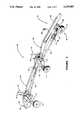
- FIG. 1is a view of the tank cleaning robot and the waste removal pump.
- FIG. 2is a detailed view of the horizontal and vertical control mechanisms of the spray nozzle, the grappling hook, and the front wheel assembly.
- FIG. 3is a view of two hose support carts connected to the II cart bracket of the tank cleaning robot prior to connection of the hydraulic supply and return lines and supply hose.
- FIG. 4is an overhead view of an oil storage tank being cleaned, the hydraulic power and control units, the tank cleaning II robot, the waste removal pump, the solvent supply tanks, and the waste fractioning tanks.
- FIG. 5is a hydraulic diagram showing the required connections for operation of the tank cleaning robot and the waste removal pump.
- FIG. 4depicts an overhead view of tank cleaning system showing an oil storage tank 1, the tank cleaning robot 2, solvent supply means 4, hydraulic power means 5, hydraulic control means 106, waste removal means 107, waste fractioning means 108, and sludge return means 109.
- Solvent supply means 4will generally comprise one or more mobile solvent holding tanks 101, which hold large quantities, typically 500 barrels, of the solvent to be used for spraying the tank interior, as well as an intermediate tank 102 containing a supply pump 103 which pumps solvent through supply hose 7 to robot 2.
- Supply pump 103is capable of generating a spraying pressure of about 300 pounds per square inch (PSI) and a flowrate of about 300 gallons per minute (GPM).
- PSIpounds per square inch
- GPSMgallons per minute
- the solvent pressureis monitored by two in-line pressure gauges 96, one of which is attached to supply hose 7 just outside storage tank I near operator 3, and another of which is attached to supply hose 7 immediately after its connection to supply pump 103.
- Holding tanks 101are fluidically connected to each other and to intermediate tank 102 by way of a main supply line 104, and solvent is transferred from holding tanks 101 using gate valves 105 positioned thereon.
- Transfer pump 67is located along main supply line 104 to facilitate the transfer of solvent from holding tanks 101 to intermediate tank 102.
- Hydraulic power means 5 and intermediate tank 102are preferably included as part of a mobile platform 6 which can be placed in a convenient location with respect to storage tank 1.
- Hydraulic power means 5is comprised primarily of a hydraulic reservoir and pump (not shown) assembled in a manner familiar to those skilled in the art, and has at least five (5) external sets of supply/return fittings 29 for use with the various components to to operated, as will be explained below.
- Hydraulic supply lines 10-13 and return lines 14-17are connected on one end to hydraulic power means 5 and on the other end to hydraulic control means 106 which is comprised of hydraulic control valves 81-84. Both supply lines 10-13 and return lines 14-17 continue from hydraulic control means 106 to their appropriate connections on robot 2, and will be explained in more detail below.
- robot 2is shown in detail and includes a frame 20, robot articulation means 8, trailing wheel 22, and washing means 23.
- Hose support train 24is also included and is shown in FIG. 3.
- Robot articulation means 8preferably comprises front tires 21, each actuated by hydraulic tire motors 28 fixedly connected to tire axle 9.
- Frame 20consists of essentially two parts, namely the cross support tube 25 between front tires 21, and supply tube 26 to which trailing tire 22 is attached.
- Cross support tube 25is preferably constructed of aluminum or other light-weight metal and forms an angle, preferably 15° at its midpoint such that front tires 21 are positioned slightly forward of the center of gravity of washing means 23 for stability.
- axle plates 27which serve as a support for tire axle 9 and hydraulic tire motor 28 for each front tire 21.
- Hydraulic tire motor 28is attached to the inner side of each axle plate 27 and each is operated independently by hydraulic control means 106.
- Supply tube 26is an elongated hollow tube which acts in part as support for washing means 23 as well as to supply solvent to washing means 23.
- Supply tube 26is also pivotable with cross support tube 25 and includes trailing wheel 22. On its rear end, supply tube 26 is open to accept supply hose 7 for attachment by threaded collar 30. Trailing wheel 22 may simply be a pivotable caster-type wheel 31 attached to a caster bracket 32 welded to supply tube 26.
- Hose support cart bracket 33also is attached to supply tube 26 and extends toward the rear of robot 2 to pivotally join with a first of several serially connected hose support carts 34, as shown in FIG. 3. Referring additionally to a more detailed depiction of washing means 23 and frame 20 in FIG.
- the front end of supply tube 26contains a pivot bracket 35 having two horizontally parallel plates 36 designed to mate with pivot plate 37 attached to the rear of the midpoint of cross support tube 25.
- Pivot pin 38is inserted through aligned holes (not shown) in both parallel plates 36 and in pivot plate 37 to pivotally connect cross support tube 25 to supply tube 26.
- the degree to which supply tube 26 may pivotshould be no more than about 20° from a center position as shown by pivot angle 119. Therefore, any manner of mechanically limiting the motion of supply tube 26 in this way would be suitable, such as by using a spring-loaded pin 39 attached to pivot bracket 35 into a curved slot 40 formed in pivot plate 37.
- Front end of supply tube 26forms a 90° bend upward near pivot bracket 35 and is connected with washing means 23 by way of horizontal rotary joint 41 which allows nozzle 42 to be moved in a horizontal plane and which maintains fluidic communication between supply tube 26 and first tube section 43.
- Washing means 23is generally comprised of horizontal control means 44, vertical control means 59, and a series of tube sections 43, 52, 54-56.
- Horizontal control means 44creates the notion of nozzle 42 in a horizontal plane.
- Hydraulic horizontal motion motor 45is bolted to motor bracket 46 which is in turn attached to supply tube 26 behind pivot bracket 35.
- Motor 45includes a motor shaft (not shown) to which driver sprocket 50 is fixedly attached in a horizontal plane.
- Driver sprocket 50meshes with chain 49 which in turn meshes with horizontal motion sprocket 51 which is fixed to vertical first tube section 43, thus allowing for reciprocating motion of nozzle 42 in a horizontal plane.
- chain guard 118is attached to motor bracket 46.
- First tube section 43forms a first 90° bend 91 toward the side of frame 20 to connect to second tube section 52 where vertical rotary joint 53 is attached which allows nozzle 42 to be moved in a vertical plane and which maintains fluidic communication between second tube section 52 and the flow path through the remaining tube sections 54-56.
- Third tube section 54is formed after a second 90° bend 92 in second tube section 52 toward the front of frame 20 and continues until it forms a third 90° bend 93 toward the middle of frame 20 to form fourth tube section 55.
- Fourth tube section 55forms a fourth 90° bend 94 toward the front of frame 20 in order to form fifth tube section 56 which directs solvent flow away from robot 2.
- Nozzle 42is attached by way of threaded coupling 57 to the end of fifth tube section 56, and contains a tapered exit portion 58 for increasing the liquid pressure leaving nozzle 42.
- Vertical control means 59comprises a double-acting hydraulic cylinder and ram 60 connected on one end to a rear bracket 61 welded to the front side of first tube section 43 and on the other end to a front bracket 62 welded to the underside of fifth tube section 56. Movement of ram 60, therefore, effectuates motion of nozzle 42 in a vertical plane. Because of the lifting strength associated with hydraulic ram 60, a hoisting capability of the present invention is readily obtainable. Therefore, grappling-type hook 63 is also suspended from fifth tube section 56 near nozzle 42 in order to pick up and deposit a waste removal pump 64 to desired locations within tank 1, as explained below.
- Waste removal pump 64is a separate hydraulic centrifugal pump powered by hydraulic supply and return lines 18, 19 connected to hydraulic power means 5 on mobile platform 6.
- Pump 64is generally of a low-speed type capable of handling non-Newtonian waste material such as the dissolved oil sludge mixed with the used cutter stock solvent, and is connected to a 3-inch diameter discharge hose 65 for delivering the waste material out of tank I for later separation of the oil sludge from the expended solvent in the waste fractioning means 108 as described below.
- Handle 66is attached to pump 64 for either manually handling pump 64 or grasping it by way of hook 63 suspended from fifth tube section 56.
- clearing blade 68is attached to cross support tube 25 by either welding or bolting along the front of robot 2.
- Clearing blade 68may simply be a rigid metal plate 69 which includes an attached rubberized strip 90 along the bottom edge of plate 69, or any other similar attachment capable of moving the accumulated waste material and expended cutter stock solvent away from the sprayed areas.
- each hose support cart 34generally includes a main support member 70, a pair of wheels 71, and a hose guide 72.
- Wheels 71are preferably 360° pivoting caster-type wheels and are attached to a cross bar 73 transversely attached to main support member 70.
- Hose guide 72may simply be a pair of vertical members 74 tall enough to retain the assembly of hydraulic supply and return lines 10-17 and the solvent supply hose 7 extending from the robot 2 during operation.
- Flat mating portion 75 having a hole 76is formed on the rear end of cart 34 for attachment with other trailing carts 34.
- each cart 34On the front end of each cart 34, a pair of parallel plates 77 having aligned holes 78 is used to engage mating portion 75 of a preceding cart 34 or the hose cart bracket 33 on supply tube 26 by insertion of a connection pin 79 through holes 78.
- Waste fractioning means 108comprises one or more fractioning tanks 110 similar to holding tanks 101 of solvent supply means 4.
- each of two fractioning tanks 110is connected to the ends of a T-section pipe ill which in turn is connected to receive waste material from discharge hose 65.
- Waste material gate valves 112are located just above each fractioning tank 110 for regulating the flow of waste material thereinto.
- Solvent recovery gate valves 113are also located on each fractioning tank 110 at a height which allows recovery of expended solvent 48 without removing any of the heavier sludge 47 accumulated at the bottom of the fractioning tanks 110. Recovered solvent 48 can thus be delivered back into main supply line 104 it through recovery lines 114 connected thereto.
- Sludge exit valves 115are located at the very bottom of each fractioning tank 110 and are connected to sludge return line 116 which delivers accumulated oil sludge 47 back to a pipeline 85 leading to the refinery. Movement of the sludge 47 through the sludge return line 116 is facilitated by operation of a sludge pump 117 operated by electrical power provided on-site by the refinery.
- the mobile platform 6 containing intermediate tank 102, supply pump 103, and hydraulic power means 5is parked close enough to storage tank 1 so that robot 2 may freely traverse the distance between circumferentially adjacent manhole entrances 80 once all line and hose connections are made.
- Spring-loaded pin 39 in supply tube pivot bracket 35is 11 disengaged to allow supply tube 26 to collapse toward cross support tube 25, and the entire frame 20 is inserted into the manhole entrance 80 to storage tank 1.
- spring-loaded pin 39engages curved slot 40 so as to limit the pivoting between supply tube 26 and cross tube 25 to about 20' to either side.
- Supply hose 7is connected to the threaded collar 30 of supply tube 26, and the hydraulic supply lines 10-13 and return lines 14-17 are connected to the horizontal motion motor, vertical motion cylinder, and left and right tire motors, respectively, as shown in FIG. 5.
- the opposite end of supply hose 7is connected to intermediate tank 102, and the opposite ends of hydraulic supply and return lines 10-17 are connected to hydraulic control valves 81-84.
- Hydraulic control valves 81-84are stationed outside of tank 1 and next to manhole entrance 80, and consist of two 4-way float position directional control valves 81, 82 for operating front tires 21, a 4-way directional control valve 83 for horizontal motion control of washing means 23 and a 4-way directional control valve 84 for vertical motion control of washing means 23. Hydraulic supply and return lines 10-13, 14-17 continue from hydraulic control valves 81-84 to the hydraulic power means 5 to complete the hydraulic circuit.
- Waste removal pump hydraulic supply line 18 and return line 19are connected on one end to waste removal pump 64 and on their opposite end to hydraulic power means 5 as shown in FIG. 5, and is operated separately from the robot 2 directly from controls on hydraulic power means 5.
- Discharge hose 65is also connected on one end to pump 64, extends outside of tank 1, and connects on the other end to waste fractioning means 108.
- Pump 64is hung from hook 63 suspended from front bracket 62, and hydraulic power is sent to the tire hydraulic motors 28 and hydraulic ram 60 on robot 2 so that robot 2 may lift pump 64 and deliver it to the desired location.
- Hydraulic ram 60is operated to lower pump 64 to tank floor 95 until hook 63 disengages itself from handle 66 on pump 64.
- Air movers 120capable of air pressures of about 125 PSI and operated from electricity supplied by the refinery are also attached to the other manhole entrances 60 in order to circulate toxic fumes outside of storage tank 1.
- Solvent supply means 4is then actuated to deliver the cutter stock to washing means 23, and cleaning of tank 1 is commenced by controlling the position of nozzle 42 and robot 2 by way of hydraulic control valves 81-84 until sludge is gradually dislodged from the surfaces of tank 1. Operator 3 still retains control of the movement of robot 2 by applying power to tire motors 28. Waste removal pump 64 is then energized from the hydraulic power means 5 to begin suctioning out dislodged sludge and expended cutter stock for delivery to the waste fractioning tanks 110.
- Waste material collected in fractioning tanks 110is allowed to settle to the extent that the sludge 47 becomes concentrated below the expended solvent 48.
- Expended solvent 48 inside fractioning tanks 110is then transfered back into main supply line 104 by opening solvent recovery valves 113 so that solvent 48 may again be used to spray the interior of tank 1.
- the collected waste materialwill have such a high concentration of sludge 47 that the viscosity of the liquid being returned to main supply line 104 will result in decreased pressure readings on in-line pressure gauges 96.
- an operator 3can switch to another fractioning tank 110 by opening another gate valve 112 on the empty fractioning tank 110 and closing the gate valve 112 on the fractioning tank 110 filled mostly with sludge 47.
- Sludge 47 existing at the bottom of fractioning tank 110is removed through sludge exit valves 115 and delivered to sludge return line 116 where sludge pump 117 assists movement of sludge 47 to the refinery pipeline 85. Meanwhile, the cleaning procedure is continued using the other fractioning tank 110 until tank 1 is satisfactorily cleaned and all of the sludge 47 is returned to the refinery 86.
Landscapes
- Engineering & Computer Science (AREA)
- Mechanical Engineering (AREA)
- Physics & Mathematics (AREA)
- Thermal Sciences (AREA)
- Chemical & Material Sciences (AREA)
- Chemical Kinetics & Catalysis (AREA)
- Cleaning In General (AREA)
Abstract
Description
Claims (27)
Priority Applications (1)
| Application Number | Priority Date | Filing Date | Title |
|---|---|---|---|
| US07/848,038US5293887A (en) | 1992-03-09 | 1992-03-09 | Robotic tank cleaning system and method |
Applications Claiming Priority (1)
| Application Number | Priority Date | Filing Date | Title |
|---|---|---|---|
| US07/848,038US5293887A (en) | 1992-03-09 | 1992-03-09 | Robotic tank cleaning system and method |
Publications (1)
| Publication Number | Publication Date |
|---|---|
| US5293887Atrue US5293887A (en) | 1994-03-15 |
Family
ID=25302176
Family Applications (1)
| Application Number | Title | Priority Date | Filing Date |
|---|---|---|---|
| US07/848,038Expired - LifetimeUS5293887A (en) | 1992-03-09 | 1992-03-09 | Robotic tank cleaning system and method |
Country Status (1)
| Country | Link |
|---|---|
| US (1) | US5293887A (en) |
Cited By (32)
| Publication number | Priority date | Publication date | Assignee | Title |
|---|---|---|---|---|
| US5435405A (en)* | 1993-05-14 | 1995-07-25 | Carnegie Mellon University | Reconfigurable mobile vehicle with magnetic tracks |
| US5451135A (en)* | 1993-04-02 | 1995-09-19 | Carnegie Mellon University | Collapsible mobile vehicle |
| US5642745A (en)* | 1994-11-18 | 1997-07-01 | Landry Service Co. | Tank cleaning system using collapsible robotic tank entry vehicle |
| EP0779111A3 (en)* | 1995-12-11 | 1997-10-22 | Taiho Ind Co | Method for treating a liquid in a tank and liquid jet device used in the method |
| US5740821A (en)* | 1996-07-09 | 1998-04-21 | Landry Service Co. Inc. | Tank cleaning using remotely controlled manway mounted robotic system |
| US5944036A (en)* | 1997-01-27 | 1999-08-31 | Allen; Henry W. | High pressure sludge remover |
| US5944035A (en)* | 1998-08-25 | 1999-08-31 | Chen; I-Lung | Detergent recycling apparatus for parts washing machine |
| USRE36465E (en)* | 1994-03-02 | 1999-12-28 | C.H. Heist Corp. | Furnace cleaning apparatus |
| US6073779A (en)* | 1999-02-24 | 2000-06-13 | Shea; Edward M. | Sludge vacuum system |
| US6141810A (en)* | 1998-12-07 | 2000-11-07 | Allen; Henry W. | Remote controlled sludge removal system |
| US6321754B1 (en)* | 1998-01-21 | 2001-11-27 | Taiho Industries Co., Ltd. | Tank washing apparatus and method |
| US6419840B1 (en) | 1999-03-30 | 2002-07-16 | Jonathan E Meincke | Cleaning system for swimming pools and the like |
| GB2376471A (en)* | 2001-02-22 | 2002-12-18 | Tsors Ltd | Method and apparatus for dissolving crude oil sludge |
| WO2003047781A1 (en)* | 2001-11-30 | 2003-06-12 | Tsors Limited | A method of, and apparatus for, dissolving crude oil sludge |
| CN1131739C (en)* | 1996-04-25 | 2003-12-24 | 太凤工业株式会社 | Method for treating liquid in tank and liquid jetting device used in method |
| US20050211637A1 (en)* | 2004-03-23 | 2005-09-29 | Sower Larry P | Sludge harvester for removing sludge from sludge ponds |
| US20060038033A1 (en)* | 2004-08-17 | 2006-02-23 | Howard Daley | Carriage for a power washer wand |
| FR2885821A1 (en)* | 2005-05-19 | 2006-11-24 | Maurice Guerin | Enclosure interior cleaning device for e.g. truck, has carriage with wheels comprising backstop system, and cleaning head delivering pressurized cleaning, disinfection and/or rinsing liquid animated for rotational movement |
| US20080048049A1 (en)* | 2006-08-24 | 2008-02-28 | Adams Randy L | Herbicide and pesticide carrier |
| ITGE20100002A1 (en)* | 2010-01-08 | 2011-07-09 | Giorgio Pucillo | APPARATUS FOR BANIFYING UNDERGROUND TANKS. |
| WO2011121197A1 (en)* | 2010-03-30 | 2011-10-06 | Veolia Proprete | Equipment for cleaning tanks intended for storing inflammable products |
| AU2006203731B2 (en)* | 2005-08-30 | 2011-11-03 | Ralph Calvert | Sludge removal apparatus |
| WO2011162816A3 (en)* | 2010-06-23 | 2012-02-16 | Ocs Technologies, L.L.C | Method and apparatus for cleaning vessels |
| WO2012151043A1 (en)* | 2011-05-02 | 2012-11-08 | Veolia Es Industrial Services, Inc. | Tank cleaning unit |
| EP2650056A1 (en)* | 2012-04-10 | 2013-10-16 | Ligiero Vargas Junior, Joel | Cleaning system for the removal of sediments from a tank |
| WO2014147268A1 (en)* | 2013-03-22 | 2014-09-25 | Agrinsal, S.A.L. | Device for the articulated connection of a pivoting irrigation structure |
| US8904596B1 (en)* | 2013-04-19 | 2014-12-09 | Leslie G. Perry | Oil spill vacuum hose support |
| US8984709B1 (en)* | 2011-10-25 | 2015-03-24 | John K. Rollins | No-entry bulk oil storage tank cleaning system |
| US9932732B1 (en)* | 2013-05-20 | 2018-04-03 | Thermaco, Inc. | Passive grease trap with lift system |
| US20220055081A1 (en)* | 2019-12-09 | 2022-02-24 | Lg Chem, Ltd. | Reactor cleaning apparatus and reactor cleaning method |
| US20220410230A1 (en)* | 2019-11-26 | 2022-12-29 | Oitech S. De R.L. De C.V | System and process for cleaning hydrocarbon storage tanks |
| CN115569942A (en)* | 2022-10-25 | 2023-01-06 | 江苏明白液压科技有限公司 | Horizontal hydraulic cylinder belt cleaning device |
Citations (16)
| Publication number | Priority date | Publication date | Assignee | Title |
|---|---|---|---|---|
| US1628141A (en)* | 1925-05-20 | 1927-05-10 | Oakite Prod Inc | Cleaning device |
| US2652282A (en)* | 1949-10-21 | 1953-09-15 | Elwood H Willetts | Irrigation apparatus |
| US2692163A (en)* | 1951-12-03 | 1954-10-19 | Frances E Shreve | Water sweeping device |
| US2746072A (en)* | 1954-04-15 | 1956-05-22 | Lumpkin James Leroy | Water spray for washing concrete pavement |
| US2879787A (en)* | 1955-10-26 | 1959-03-31 | Carl B Ingram | Wheeled pipe line carrier |
| US2889993A (en)* | 1954-11-02 | 1959-06-09 | Willetts | Mobile irrigator or sprinkler |
| US3057559A (en)* | 1959-10-26 | 1962-10-09 | Carl B Ingram | Coupling carriage for articulated mobile sprinkler lines |
| US3477178A (en)* | 1965-10-20 | 1969-11-11 | Capvac Ind Inc | Cylinder treater apparatus |
| US3534746A (en)* | 1968-08-21 | 1970-10-20 | Samuel Posner | Portable cleaner for trailer interiors |
| US3645004A (en)* | 1968-08-27 | 1972-02-29 | English Clays Lovering Pochin | Drying of efflorescent material |
| US4141374A (en)* | 1976-06-16 | 1979-02-27 | Wash Wagon Corporation | Trailer washing apparatus |
| US4777971A (en)* | 1984-05-09 | 1988-10-18 | Service National Electricite De France | Handling machine able to move along a wall with a random slope |
| US4784166A (en)* | 1987-11-23 | 1988-11-15 | Brager Douglas R | Truck washing machine for washing trailer interiors using water under pressure as remote sole source of power, control and wash liquid |
| US4798334A (en)* | 1987-09-25 | 1989-01-17 | New West Engineering, Ltd. | Apparatus for spraying a liquid in a vessel |
| US4828626A (en)* | 1986-08-15 | 1989-05-09 | Crystal Pools, Inc. | Cleaning system for swimming pools and the like |
| US4945933A (en)* | 1988-04-11 | 1990-08-07 | Serv-Tech, Inc. | Liquid circulator useful for dispersing sediment contained in a storage tank |
- 1992
- 1992-03-09USUS07/848,038patent/US5293887A/ennot_activeExpired - Lifetime
Patent Citations (16)
| Publication number | Priority date | Publication date | Assignee | Title |
|---|---|---|---|---|
| US1628141A (en)* | 1925-05-20 | 1927-05-10 | Oakite Prod Inc | Cleaning device |
| US2652282A (en)* | 1949-10-21 | 1953-09-15 | Elwood H Willetts | Irrigation apparatus |
| US2692163A (en)* | 1951-12-03 | 1954-10-19 | Frances E Shreve | Water sweeping device |
| US2746072A (en)* | 1954-04-15 | 1956-05-22 | Lumpkin James Leroy | Water spray for washing concrete pavement |
| US2889993A (en)* | 1954-11-02 | 1959-06-09 | Willetts | Mobile irrigator or sprinkler |
| US2879787A (en)* | 1955-10-26 | 1959-03-31 | Carl B Ingram | Wheeled pipe line carrier |
| US3057559A (en)* | 1959-10-26 | 1962-10-09 | Carl B Ingram | Coupling carriage for articulated mobile sprinkler lines |
| US3477178A (en)* | 1965-10-20 | 1969-11-11 | Capvac Ind Inc | Cylinder treater apparatus |
| US3534746A (en)* | 1968-08-21 | 1970-10-20 | Samuel Posner | Portable cleaner for trailer interiors |
| US3645004A (en)* | 1968-08-27 | 1972-02-29 | English Clays Lovering Pochin | Drying of efflorescent material |
| US4141374A (en)* | 1976-06-16 | 1979-02-27 | Wash Wagon Corporation | Trailer washing apparatus |
| US4777971A (en)* | 1984-05-09 | 1988-10-18 | Service National Electricite De France | Handling machine able to move along a wall with a random slope |
| US4828626A (en)* | 1986-08-15 | 1989-05-09 | Crystal Pools, Inc. | Cleaning system for swimming pools and the like |
| US4798334A (en)* | 1987-09-25 | 1989-01-17 | New West Engineering, Ltd. | Apparatus for spraying a liquid in a vessel |
| US4784166A (en)* | 1987-11-23 | 1988-11-15 | Brager Douglas R | Truck washing machine for washing trailer interiors using water under pressure as remote sole source of power, control and wash liquid |
| US4945933A (en)* | 1988-04-11 | 1990-08-07 | Serv-Tech, Inc. | Liquid circulator useful for dispersing sediment contained in a storage tank |
Cited By (43)
| Publication number | Priority date | Publication date | Assignee | Title |
|---|---|---|---|---|
| US5451135A (en)* | 1993-04-02 | 1995-09-19 | Carnegie Mellon University | Collapsible mobile vehicle |
| US5435405A (en)* | 1993-05-14 | 1995-07-25 | Carnegie Mellon University | Reconfigurable mobile vehicle with magnetic tracks |
| USRE36465E (en)* | 1994-03-02 | 1999-12-28 | C.H. Heist Corp. | Furnace cleaning apparatus |
| US5642745A (en)* | 1994-11-18 | 1997-07-01 | Landry Service Co. | Tank cleaning system using collapsible robotic tank entry vehicle |
| EP0779111A3 (en)* | 1995-12-11 | 1997-10-22 | Taiho Ind Co | Method for treating a liquid in a tank and liquid jet device used in the method |
| US5810473A (en)* | 1995-12-11 | 1998-09-22 | Taiho Industries Co., Ltd. | Method for treating liquid in a tank and liquid jetting device used in the method |
| CN1131739C (en)* | 1996-04-25 | 2003-12-24 | 太凤工业株式会社 | Method for treating liquid in tank and liquid jetting device used in method |
| US5740821A (en)* | 1996-07-09 | 1998-04-21 | Landry Service Co. Inc. | Tank cleaning using remotely controlled manway mounted robotic system |
| US5944036A (en)* | 1997-01-27 | 1999-08-31 | Allen; Henry W. | High pressure sludge remover |
| US6321754B1 (en)* | 1998-01-21 | 2001-11-27 | Taiho Industries Co., Ltd. | Tank washing apparatus and method |
| US5944035A (en)* | 1998-08-25 | 1999-08-31 | Chen; I-Lung | Detergent recycling apparatus for parts washing machine |
| US6141810A (en)* | 1998-12-07 | 2000-11-07 | Allen; Henry W. | Remote controlled sludge removal system |
| US6073779A (en)* | 1999-02-24 | 2000-06-13 | Shea; Edward M. | Sludge vacuum system |
| US6419840B1 (en) | 1999-03-30 | 2002-07-16 | Jonathan E Meincke | Cleaning system for swimming pools and the like |
| GB2376471A (en)* | 2001-02-22 | 2002-12-18 | Tsors Ltd | Method and apparatus for dissolving crude oil sludge |
| GB2376471B (en)* | 2001-02-22 | 2004-06-09 | Tsors Ltd | Method of and apparatus for dissolving crude oil sludge |
| WO2003047781A1 (en)* | 2001-11-30 | 2003-06-12 | Tsors Limited | A method of, and apparatus for, dissolving crude oil sludge |
| US20050045212A1 (en)* | 2001-11-30 | 2005-03-03 | Howe William Benjamin | Method of, and apparatus for, dissolving crude oil sludge |
| US20050211637A1 (en)* | 2004-03-23 | 2005-09-29 | Sower Larry P | Sludge harvester for removing sludge from sludge ponds |
| US7181871B2 (en)* | 2004-03-23 | 2007-02-27 | Crystal Park Technologies, Llc | Sludge harvester for removing sludge from sludge ponds |
| US7121484B2 (en)* | 2004-08-17 | 2006-10-17 | Howard Daley | Carriage for a power washer wand |
| US20060038033A1 (en)* | 2004-08-17 | 2006-02-23 | Howard Daley | Carriage for a power washer wand |
| WO2007000538A3 (en)* | 2005-05-19 | 2007-04-12 | Michaud Grosbenoit Frederic | Device for cleaning the inside space of an enclosure, in particular of a truck or container and a system comprising said device |
| FR2885821A1 (en)* | 2005-05-19 | 2006-11-24 | Maurice Guerin | Enclosure interior cleaning device for e.g. truck, has carriage with wheels comprising backstop system, and cleaning head delivering pressurized cleaning, disinfection and/or rinsing liquid animated for rotational movement |
| AU2006203731B2 (en)* | 2005-08-30 | 2011-11-03 | Ralph Calvert | Sludge removal apparatus |
| US20080048049A1 (en)* | 2006-08-24 | 2008-02-28 | Adams Randy L | Herbicide and pesticide carrier |
| US7909265B2 (en)* | 2006-08-24 | 2011-03-22 | Randy L Adams | Herbicide and pesticide carrier |
| ITGE20100002A1 (en)* | 2010-01-08 | 2011-07-09 | Giorgio Pucillo | APPARATUS FOR BANIFYING UNDERGROUND TANKS. |
| WO2011121197A1 (en)* | 2010-03-30 | 2011-10-06 | Veolia Proprete | Equipment for cleaning tanks intended for storing inflammable products |
| FR2958191A1 (en)* | 2010-03-30 | 2011-10-07 | Veolia Proprete | EQUIPMENT FOR CLEANING TANKS FOR STORING FLAMMABLE PRODUCTS |
| CN103002996A (en)* | 2010-06-23 | 2013-03-27 | Ocs技术公司 | Method and apparatus for cleaning containers |
| WO2011162816A3 (en)* | 2010-06-23 | 2012-02-16 | Ocs Technologies, L.L.C | Method and apparatus for cleaning vessels |
| WO2012151043A1 (en)* | 2011-05-02 | 2012-11-08 | Veolia Es Industrial Services, Inc. | Tank cleaning unit |
| US8984709B1 (en)* | 2011-10-25 | 2015-03-24 | John K. Rollins | No-entry bulk oil storage tank cleaning system |
| EP2650056A1 (en)* | 2012-04-10 | 2013-10-16 | Ligiero Vargas Junior, Joel | Cleaning system for the removal of sediments from a tank |
| WO2014147268A1 (en)* | 2013-03-22 | 2014-09-25 | Agrinsal, S.A.L. | Device for the articulated connection of a pivoting irrigation structure |
| US8904596B1 (en)* | 2013-04-19 | 2014-12-09 | Leslie G. Perry | Oil spill vacuum hose support |
| US9932732B1 (en)* | 2013-05-20 | 2018-04-03 | Thermaco, Inc. | Passive grease trap with lift system |
| US20220410230A1 (en)* | 2019-11-26 | 2022-12-29 | Oitech S. De R.L. De C.V | System and process for cleaning hydrocarbon storage tanks |
| US20220055081A1 (en)* | 2019-12-09 | 2022-02-24 | Lg Chem, Ltd. | Reactor cleaning apparatus and reactor cleaning method |
| US11998963B2 (en)* | 2019-12-09 | 2024-06-04 | Lg Chem, Ltd. | Reactor cleaning apparatus and reactor cleaning method |
| CN115569942A (en)* | 2022-10-25 | 2023-01-06 | 江苏明白液压科技有限公司 | Horizontal hydraulic cylinder belt cleaning device |
| CN115569942B (en)* | 2022-10-25 | 2023-08-22 | 江苏明白液压科技有限公司 | Cylinder barrel cleaning device for transverse hydraulic cylinder |
Similar Documents
| Publication | Publication Date | Title |
|---|---|---|
| US5293887A (en) | Robotic tank cleaning system and method | |
| US4817653A (en) | Tank cleaning, water washing robot | |
| US7261109B2 (en) | Remotely operated cleaning device, especially suitable for storage tanks on vessels | |
| US6315648B1 (en) | Apparatus for pressure treating a surface | |
| AU2017268362B2 (en) | Device for removing catalyst and other material from refinery and petrochemical reactors and other vessels | |
| EP0215396B1 (en) | Mobile articulatable tube bundle cleaner | |
| US4770711A (en) | Method for cleaning chemical sludge deposits of oil storage tanks | |
| US9492907B2 (en) | Surface media blasting system and method | |
| US5018544A (en) | Apparatus for cleaning heat exchanger tube bundles | |
| US9205470B2 (en) | Robotic tank cleaning device and method | |
| US12151270B1 (en) | Method and apparatus, including hose reel, for cleaning an oil and gas well riser assembly with multiple tools simultaneously | |
| EP3643414B1 (en) | An ultra-high-pressure water jetting (uhpwj) hydro-blasting cleaning system for surfaces | |
| EP0625078B1 (en) | Remote controlled sludge removal apparatus | |
| US5335395A (en) | Remote controlled sludge removal apparatus | |
| RU2616051C1 (en) | Mobile technological complex of hard tanks cleaning and washing | |
| WO2012151044A1 (en) | Tank cleaning unit | |
| RU2644905C1 (en) | Technological complex for washing and cleaning hard vertical tanks | |
| WO2024188495A1 (en) | Machine for removing sediment, dregs and the like | |
| EP3241624B1 (en) | Apparatus and method for depleting a tank | |
| WO2024188497A1 (en) | Machine for removing sediment, dregs, and the like | |
| US7160473B2 (en) | Manually controlled skimming of industrial oil contaminants | |
| CN114632774B (en) | Cleaning device for storage tank equipment and using method thereof | |
| EP0918576B1 (en) | A motorised vehicle for cleaning and degassing underground storage tanks | |
| EP0275690A1 (en) | A method of tank cleaning and a tractor for use therein | |
| WO2011163014A2 (en) | A vacuum nozzle assembly and system for removal of pollutants from hard surfaces |
Legal Events
| Date | Code | Title | Description |
|---|---|---|---|
| AS | Assignment | Owner name:LOUISIANA SEED CAPITAL FUND, LIMITED PARTNERSHIP, Free format text:ASSIGNMENT OF ASSIGNORS INTEREST;ASSIGNOR:THIBODEAUX, RAY;REEL/FRAME:008059/0838 Effective date:19960718 Owner name:LOUISIANA ECONOMIC DEVELOPMENT CORPORATION, LOUISI Free format text:ASSIGNMENT OF ASSIGNORS INTEREST;ASSIGNOR:THIBODEAUX, RAY;REEL/FRAME:008059/0838 Effective date:19960718 | |
| AS | Assignment | Owner name:PETROCHEMICAL SERVICES, INCORPORATED, LOUISIANA Free format text:ASSIGNMENT OF ASSIGNORS INTEREST;ASSIGNORS:LOUISIANA SEED CAPITAL FUND, LIMITED PARTNERSHIP;LOUISIANA ECONOMIC DEVELOPMENT CORPORATION;REEL/FRAME:008194/0963 Effective date:19960821 | |
| AS | Assignment | Owner name:WHITNEY NATIONAL BANK, LOUISIANA Free format text:SECURITY INTEREST;ASSIGNOR:PETROCHEMICAL SERVICES, INCORPORATED;REEL/FRAME:008268/0436 Effective date:19961127 | |
| REMI | Maintenance fee reminder mailed | ||
| FP | Lapsed due to failure to pay maintenance fee | Effective date:19980318 | |
| FEPP | Fee payment procedure | Free format text:PETITION RELATED TO MAINTENANCE FEES FILED (ORIGINAL EVENT CODE: PMFP); ENTITY STATUS OF PATENT OWNER: SMALL ENTITY | |
| FEPP | Fee payment procedure | Free format text:PETITION RELATED TO MAINTENANCE FEES GRANTED (ORIGINAL EVENT CODE: PMFG); ENTITY STATUS OF PATENT OWNER: SMALL ENTITY | |
| FPAY | Fee payment | Year of fee payment:4 | |
| SULP | Surcharge for late payment | ||
| STCF | Information on status: patent grant | Free format text:PATENTED CASE | |
| FPAY | Fee payment | Year of fee payment:8 | |
| PRDP | Patent reinstated due to the acceptance of a late maintenance fee | Effective date:20010713 | |
| REMI | Maintenance fee reminder mailed | ||
| FPAY | Fee payment | Year of fee payment:12 | |
| SULP | Surcharge for late payment | Year of fee payment:11 |