US5293871A - System for ultrasonically determining corneal layer thicknesses and shape - Google Patents
System for ultrasonically determining corneal layer thicknesses and shapeDownload PDFInfo
- Publication number
- US5293871A US5293871AUS08/089,781US8978193AUS5293871AUS 5293871 AUS5293871 AUS 5293871AUS 8978193 AUS8978193 AUS 8978193AUS 5293871 AUS5293871 AUS 5293871A
- Authority
- US
- United States
- Prior art keywords
- ultrasonic apparatus
- radio frequency
- signal
- recited
- analytic
- Prior art date
- Legal status (The legal status is an assumption and is not a legal conclusion. Google has not performed a legal analysis and makes no representation as to the accuracy of the status listed.)
- Expired - Lifetime
Links
- 210000001747pupilAnatomy0.000claimsabstractdescription17
- 210000003560epithelium cornealAnatomy0.000claimsabstractdescription8
- 238000002592echocardiographyMethods0.000claimsabstractdescription6
- 210000004087corneaAnatomy0.000claimsdescription20
- 238000012546transferMethods0.000claimsdescription9
- 238000004458analytical methodMethods0.000claimsdescription7
- 230000002123temporal effectEffects0.000claimsdescription7
- 230000001179pupillary effectEffects0.000claimsdescription6
- 238000001514detection methodMethods0.000claimsdescription5
- 238000003384imaging methodMethods0.000claimsdescription4
- 208000028006Corneal injuryDiseases0.000claimsdescription2
- 230000001575pathological effectEffects0.000claimsdescription2
- 230000002401inhibitory effectEffects0.000claims2
- 210000003683corneal stromaAnatomy0.000claims1
- 238000002604ultrasonographyMethods0.000abstractdescription12
- 238000005259measurementMethods0.000abstractdescription6
- 230000003287optical effectEffects0.000abstractdescription5
- 238000012544monitoring processMethods0.000abstractdescription3
- 238000013507mappingMethods0.000abstractdescription2
- 238000000034methodMethods0.000description20
- 230000006870functionEffects0.000description16
- 210000001519tissueAnatomy0.000description9
- 238000012512characterization methodMethods0.000description4
- 238000010586diagramMethods0.000description4
- 210000000981epitheliumAnatomy0.000description4
- 238000012545processingMethods0.000description3
- 238000013519translationMethods0.000description3
- 210000004045bowman membraneAnatomy0.000description2
- 238000006243chemical reactionMethods0.000description2
- 238000009499grossingMethods0.000description2
- 238000012986modificationMethods0.000description2
- 230000004048modificationEffects0.000description2
- 230000037390scarringEffects0.000description2
- 238000001356surgical procedureMethods0.000description2
- XLYOFNOQVPJJNP-UHFFFAOYSA-NwaterSubstancesOXLYOFNOQVPJJNP-UHFFFAOYSA-N0.000description2
- FAPWRFPIFSIZLT-UHFFFAOYSA-MSodium chlorideChemical compound[Na+].[Cl-]FAPWRFPIFSIZLT-UHFFFAOYSA-M0.000description1
- 238000002679ablationMethods0.000description1
- 230000003321amplificationEffects0.000description1
- 230000003444anaesthetic effectEffects0.000description1
- 230000008901benefitEffects0.000description1
- 239000003086colorantSubstances0.000description1
- 230000002596correlated effectEffects0.000description1
- 230000000875corresponding effectEffects0.000description1
- 238000009795derivationMethods0.000description1
- 210000005081epithelial layerAnatomy0.000description1
- 238000001914filtrationMethods0.000description1
- 239000005357flat glassSubstances0.000description1
- 239000011521glassSubstances0.000description1
- 230000006872improvementEffects0.000description1
- 238000000608laser ablationMethods0.000description1
- 230000007246mechanismEffects0.000description1
- 238000003199nucleic acid amplification methodMethods0.000description1
- 230000007170pathologyEffects0.000description1
- 238000007781pre-processingMethods0.000description1
- 230000008569processEffects0.000description1
- 230000004044responseEffects0.000description1
- 238000007493shaping processMethods0.000description1
- 238000001228spectrumMethods0.000description1
- 238000010183spectrum analysisMethods0.000description1
- 230000000699topical effectEffects0.000description1
- 230000001131transforming effectEffects0.000description1
- 230000001960triggered effectEffects0.000description1
- 238000012285ultrasound imagingMethods0.000description1
- 238000012795verificationMethods0.000description1
Images


Classifications
- A—HUMAN NECESSITIES
- A61—MEDICAL OR VETERINARY SCIENCE; HYGIENE
- A61B—DIAGNOSIS; SURGERY; IDENTIFICATION
- A61B18/00—Surgical instruments, devices or methods for transferring non-mechanical forms of energy to or from the body
- A61B18/04—Surgical instruments, devices or methods for transferring non-mechanical forms of energy to or from the body by heating
- A61B18/12—Surgical instruments, devices or methods for transferring non-mechanical forms of energy to or from the body by heating by passing a current through the tissue to be heated, e.g. high-frequency current
- A61B18/1206—Generators therefor
- A—HUMAN NECESSITIES
- A61—MEDICAL OR VETERINARY SCIENCE; HYGIENE
- A61B—DIAGNOSIS; SURGERY; IDENTIFICATION
- A61B8/00—Diagnosis using ultrasonic, sonic or infrasonic waves
- A61B8/10—Eye inspection
- G—PHYSICS
- G01—MEASURING; TESTING
- G01S—RADIO DIRECTION-FINDING; RADIO NAVIGATION; DETERMINING DISTANCE OR VELOCITY BY USE OF RADIO WAVES; LOCATING OR PRESENCE-DETECTING BY USE OF THE REFLECTION OR RERADIATION OF RADIO WAVES; ANALOGOUS ARRANGEMENTS USING OTHER WAVES
- G01S15/00—Systems using the reflection or reradiation of acoustic waves, e.g. sonar systems
- G01S15/88—Sonar systems specially adapted for specific applications
- G01S15/89—Sonar systems specially adapted for specific applications for mapping or imaging
- G01S15/8906—Short-range imaging systems; Acoustic microscope systems using pulse-echo techniques
- G01S15/8934—Short-range imaging systems; Acoustic microscope systems using pulse-echo techniques using a dynamic transducer configuration
- G01S15/8938—Short-range imaging systems; Acoustic microscope systems using pulse-echo techniques using a dynamic transducer configuration using transducers mounted for mechanical movement in two dimensions
- G—PHYSICS
- G01—MEASURING; TESTING
- G01S—RADIO DIRECTION-FINDING; RADIO NAVIGATION; DETERMINING DISTANCE OR VELOCITY BY USE OF RADIO WAVES; LOCATING OR PRESENCE-DETECTING BY USE OF THE REFLECTION OR RERADIATION OF RADIO WAVES; ANALOGOUS ARRANGEMENTS USING OTHER WAVES
- G01S7/00—Details of systems according to groups G01S13/00, G01S15/00, G01S17/00
- G01S7/52—Details of systems according to groups G01S13/00, G01S15/00, G01S17/00 of systems according to group G01S15/00
- G01S7/52017—Details of systems according to groups G01S13/00, G01S15/00, G01S17/00 of systems according to group G01S15/00 particularly adapted to short-range imaging
- G01S7/52023—Details of receivers
- G01S7/52025—Details of receivers for pulse systems
- G01S7/52026—Extracting wanted echo signals
- G01S7/52028—Extracting wanted echo signals using digital techniques
- A—HUMAN NECESSITIES
- A61—MEDICAL OR VETERINARY SCIENCE; HYGIENE
- A61B—DIAGNOSIS; SURGERY; IDENTIFICATION
- A61B18/00—Surgical instruments, devices or methods for transferring non-mechanical forms of energy to or from the body
- A61B2018/00636—Sensing and controlling the application of energy
- A61B2018/00773—Sensed parameters
- A61B2018/00875—Resistance or impedance
Definitions
- This inventionrelates to ultrasonography, and more particularly, to an ultrasonic device for accurately determining individual layer thicknesses and shape of a patient's cornea.
- the human corneal epitheliumconsists centrally of five layers of squamous cells with a thickness in the range of 50 to 60 microns. Peripherally, the human corneal epithelium consists of eleven or more layers. With the onset of surgical treatments to the surface of the cornea, e.g., radial keratotomy, excimer laser shaping of the external surface of the cornea, etc., it has become vitally important to have an accurate map of thickness and contour variations of the various corneal layers.
- Slit-lamp micropachymetryis presently the most widely used method for measuring the thickness of the corneal epithelium and corneal scarring.
- Such micropachymetry and other optical pachymetric methodssuffer from a widely varying measurement reproducability, even in the hands of experienced users. For instance, precision for slit-lamp corneal pachymetry has been reported to vary between 5.6 and 19 microns for the same surface.
- optical methodsexhibit the disadvantages of being limited to situations where the media is optically transparent--a condition not often present in areas of corneal scarring.
- Gammellstated that it was known that the analytic signal correlated to the rate of arrival of energy, i.e., that the square of the magnitude of the analytic signal was proportional to the instantaneous rate-of-arrival of the total energy of the reflected signal. He contrasted this result to the fact that the square of the real signal, was proportional to the rate of arrival of only one of the components of the energy. As a result, the square of the real signal was zero in any instant when one of the component energies was zero, whereas the square of the analytic signal magnitude was only zero when the total instantaneous energy was zero. As a result, use of the analytic signal magnitude enabled optimal estimation of interface location due to the more accurate representation of instantaneous returned energy. However, Gammell employed the analytic signal in lieu of rectification of the ultrasound signal.
- the Fourier transform of a complex ultrasonic signalcan be obtained from the Fourier transform of one of its components, by suppressing the negative frequency contributions.
- the Fourier transform of a real signalis always a symmetrical function, with a total frequency bandwidth of twice the central Fourier frequency. Therefore, the obtaining of the full complex analytic signal was performed by first Fourier transforming the real echo data using a complex fast Fourier transform procedure. Then, all negative frequency components of the Fourier spectrum were set equal to zero and an inverse fast Fourier transform was performed to reconstruct the full analytic signal. The magnitude of the analytic signal was then calculated as the square root of the sum of the squares of the real and imaginary parts at each point in time.
- An ultrasound systemthat enables determination of layer contours and thicknesses of a multi-layer organic body includes a transmitter/receiver for obtaining a radio frequency signal from echoes over a plurality of points on the organic surface. Each radio frequency signal is then deconvolved to remove apparatus generated noise and filtered to create an analytic signal that exhibits a magnitude related to an instantaneous rate of arrival of total echo energy received by the transmitter/receiver. Analytic signals from adjacent parallel scans are then cross-correlated and magnitude detected to determine energy peaks to enable accurate determination of echo producing surfaces of each layer of the multi-layer organic body across the plurality of interrogation points.
- a pupil monitoring systemis included that disables the measurement system if the pupil's gaze wanders so as to cause a diversion of the optical axis.
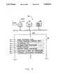
- FIG. 1is a schematic view of apparatus that incorporates the invention.
- FIG. 2is a perspective view of a cornea, indicating a direction of scans of an ultrasonic transducer.
- FIG. 3illustrates a block diagram of electrical portions of the system of FIG. 1.
- FIG. 4is a block diagram showing further details of the computer shown in FIG. 3.
- FIG. 5is a high level logical flow diagram helpful in understanding the operation of the invention.
- FIG. 6illustrates the frequency band pass of a filter function employed to derive an analytic signal from a returned echo trace.
- FIGS. 7A-7Cillustrate waveforms, helpful in understanding the operation of the invention.
- FIG. 1a schematic drawing of a system is schematically shown that incorporates the invention and is positioned over a supinely positioned patient.
- An eye 10whose cornea is to be mapped is provided with a drop of topical anesthetic and is held open with a lid speculum.
- the patientis instructed to focus his other eye 12 upon a fixation light 14 so as to provide a vertical direction of gaze for both eyes 10 and 12.
- a beam splitter 16is positioned between eye 12 and light source 14 and enables the pupil of eye 12 to be imaged by a camera 16.
- the pupillary position of eye 10can be implied and the system automatically disabled should the patient's gaze wander from a vertical axis.
- a normal saline water bath 18is established around eye 10 by the use of a sterile drape 20 that is supported by a ring stand 22.
- the scanning systemis illustrated schematically and comprises a high frequency ultrasonic transducer 24 which is spherically focused onto the surface of cornea 26.
- Transducer 24is attached to a motion control system that comprises a linear translation motor 28 and an arc translation motor 30 that are aligned at right angles to each other.
- Translation motor 30causes a carriage 32 (to which transducer 24 is affixed) to move bilaterally along a curved track 34 in the directions shown by arrows 36.
- Translational motor 28is also affixed to carriage 32 and enables the movement of transducer 24 both into and out of the plane of the paper.
- Track 34is designed to closely follow, if not duplicate, the curvature of cornea 26.
- ultrasonic beam 38will remain substantially perpendicular to the surface of cornea 26.
- the perpendicularity of beam 38assures that oblique reflections from corneal surface 26 are minimized so as to maximize the reflected signal energy.
- perpendicularityfurther enables precise corneal thickness measurements to be obtained.
- FIG. 2a perspective view is shown of cornea 26 with a scan plane 40 illustrating the direction of motion of transducer 24.
- Transducer 24makes a complete scan of cornea 26 along the axis indicated by arrows 42 for each radial position of scan plane 40.
- transducer 24is moved to create a new scan plane 44 (shown dotted) by translational motor and translational motor 28 then causes an additional full scan to be accomplished.
- translational motors 28 and 30are connected to a motor controller 50 whose operation is, in turn, controlled by a computer 52.
- a display 54provides an ability to visualize various individual A-type or B-type scans of cornea 26.
- a pulser/receiver 56controls transducer 24 in the known manner and provides an output to A/D converter 58 wherein analog scan signals are converted to a plurality of sampled digital values.
- Computer 52is provided with digitized scan values after they are accumulated by A/D converter 58 and then is operated to determine the contours and thicknesses of various layers of cornea 26 over the scanned portions of its surface.
- transducer 24provides a very high frequency output (e.g., 50 MHz or more). Transducer 24 is initially positioned so as to be vertically oriented over cornea 26. The ultrasonic echoes are amplified by pulser/receiver 56 and may be displayed to initially enable adjustment of the range of transducer 24 from the eye so that the focal point of beam 38 is on or just anterior to the surface of cornea 26.
- a very high frequency outpute.g., 50 MHz or more.
- Amplification gain of pulser/receiver 56is adjusted so that the observed echoes are of maximum amplitude, but are not clipped, i.e., not beyond voltage range of A/D converter 58.
- computer 52is actuated to commence an automatic scan mode wherein pulser/receiver 56 is placed in an externally triggered mode.
- Computer 52then begins to issue commands to motor controller 50 such that motors 28 and 30 cause transducer 24 to perform a series of parallel, arc shaped scans across cornea 26 at fixed spatial intervals.
- pulser/receiver 56emits single interrogating ultrasonic pulses at regularly spaced spatial intervals.
- A/D converter 58which sequentially samples the echo and provides digitized echo data to computer 52.
- A/D converter 58may sample the received echo signal at the rate of 200 MHz so as to provide 2048 eight bit samples per echo of digitized data to computer 52.
- A/D converter 58contains (not shown) a high speed 256k byte, high speed memory which stores digitized echo values from a single scan. After each arc-scan, the 256k bytes are transferred to computer 52 and are stored in random access memory (RAM) stored therein.
- RAMrandom access memory
- Pupil detector 60includes a microprocessor and an image buffer which enable successive pupil scans to be compared and for deviations therein to be detected and signaled to computer 52.
- the pupil position of eye 12is monitored at regular intervals during each arc scan and compared against a previously determined vertical gaze position that is acquired initially. If the pupillary position is found to have deviated by more than a set tolerance level (e.g., 0.25 mm), scan motion and data acquisition are interrupted and pupillary direction is monitored until the gaze is again within tolerance, at which time scanning is continued. Since in most cases, the optical axes of eyes 10 and 12 are parallel, any wandering in the gaze of eye 12 indicates a similar wandering in the gaze direction of eye 10. Thus, this procedure ensures that no significant drift in eye direction occurs during scanning.
- a set tolerance levele.g. 0.25 mm
- Computer 52includes an arithmetic logic unit 64, disk drive 66, and random access memory (RAM) 68. Both scan data from A/D converter 58 and pupil data from pupil detect module 60 (FIG. 3) are fed to computer 52 via input/output module 70.
- Analysis of parallel scan datainvolves a number of procedures that enable the scan data to provide highly accurate indications of tissue interface echoes. Those procedures are carried out by subroutines that are found in RAM 68 and operate upon radio frequency data 72 stored therein. Initially, Fourier transform 74 of the transfer function of the ultrasound system shown in FIGS. 1 and 3 is stored for subsequent performance of a deconvolution procedure, wherein system-generated artifacts are removed from the received radio frequency data.
- a fast Fourier transform (FFT)/inverse FFT procedure 76is stored for converting the radio frequency data to the frequency domain.
- the radio frequency dataafter conversion, is subjected to a deconvolution procedure wherein the system transfer function's FFT values are removed from the FFT of the radio frequency data to eliminate system-generated noise therefrom.
- a prestored filter function 80is stored in RAM 68 and defines a bandpass that eliminates all negative frequency values that results from the FFT conversion of the radio frequency data.
- the application of filter function 80 to the FFT of the deconvolved radio frequency datais performed by analytic signal procedure 82 which enables the derivation of an analytic signal from the radio frequency data.
- the latter procedureincludes an inverse FFT operation that provides a temporal analytic signal.
- the temporal analytic signalis then subjected to both magnitude and peak determination procedures (employing a cross-correlation operation) to identify reflection peaks. Finally, these peak positions are used to define the surfaces of individual corneal layers. From these surface positions, the shape and thickness of individual corneal layers is derived.
- a system transfer functionis derived to enable a subsequent removal from the radio frequency signal of system-derived artifacts.
- the system transfer functionis achieved by pointing transducer 24 at a flat glass plate which has been immersed in a water bath. Transducer 24 has its point of focus fixed on the surface of the glass plate and the resulting echo is digitized and stored.
- the system transfer functionis then achieved by subjecting the resulting echo to an FFT analysis to convert the signal to the frequency domain. That FFT transfer function is then stored for subsequent use in a deconvolution procedure.
- the radio frequency dataincludes both positive and negative going components (shown in analog form).
- the peak of waveform 120is at approximately 240 microns and that no subsequent peak clearly illustrates the boundary between the cornea's epithelium and stroma.
- further processingwill indicate that the actual corneal surface resides at 250 microns (not 240 microns) and that the boundary between the epithelium and stroma lies at 300 microns.
- an FFT of the radio frequency datais calculated to convert the temporal signal waveform shown in FIG. 7a to a frequency domain waveform (box 94).
- a 50 MHz center frequency for transducer 24those skilled in the art will understand that the actual output from transducer 24 is a band of frequencies that spans approximately +/-25 MHz about the 50 MHz center frequency.
- the FFT procedureproduces a frequency domain waveform where negative frequency components of the scan signal are complex conjugates of the corresponding positive frequency components.
- the negative frequency componentswill be subsequently eliminated by application of a filter function; however, prior to that operation, the frequency domain FFT transform is deconvolved by removing system-generated signal components therefrom.
- This procedureis accomplished by accessing the FFT of the system transfer function (box 96) and dividing the FFT of the radio frequency data thereby.
- the division of one Fourier transform by anotheris equivalent in the time domain to a deconvolution that effectively removes system-generated artifacts from the radio frequency echo data (box 98).
- a filter function with negative frequency components set equal to zerois accessed (box 100).
- the frequency response characteristic of the filter functiontakes the form shown in FIG. 6.
- the deconvolved FFT of the radio frequency datais then multiplied by the filter function to obtain an FFT of the analytic signal (box 102).
- the filter functionis set equal to zero in frequency ranges where low signal-to-noise ratios are present.
- peaks 122 and 124clearly illustrate the anterior and posterior boundaries of the epithelium and that peak 126 illustrates the posterior boundary of the stroma.
- plural adjacent scan linese.g. 5 are temporally aligned, added and then averaged (box 106) to enhance the resulting signal to noise ratio (see FIG. 7c). Because distances between a corneal surface and an ultrasonic transducer vary from scan line to scan line, there is often an offset, over adjacent scans, in the observed peaks. This offset must be corrected to assure highly accurate measurements.
- temporal alignment of adjacent scan linesis performed by cross-correlating a series of adjacent analytic signal scan lines, followed by a time shift of the signals to obtain optimal radio frequency analytic signal trace alignments. Subsequently, the adjacent aligned signals are added and averaged.
- the digital magnitudes of the averaged signal waveformare now analyzed to detect the peaks of the resulting return signals, with the peaks being used to calculate tissue thicknesses and contours (box 108).
- Clinically useful resultsconsist of the absolute positions about each corneal surface, the rates of curvature of these surfaces, and the thickness of each layer: the epithelium distance between the corneal surface and Bowman's membrane, the stroma (distance between Bowman's membrane and the posterior surface), and the corneal overall (distance between the anterior and posterior corneal surfaces).
- the corneal mapmay be displayed in false-color where a range of colors is used to represent the range of a specified corneal parameter.
- Such parametermight be a contour map of the cornea.
- Numeric information, such as the thickness of the cornea at a specified sitemay also be obtained interactively by cursor movement.
- Superimposition of the pupil position on a mapalso provides a useful landmark as the position of the iris (hence the pupil) is apparent in ultrasound images and may be utilized. Demarkation of the pupil's boundary in the scan set produces a set of positional values to which a circle can be fit using the method of least squares. This circle can be included in the topographic in pachymetric maps.
- the above described processnot only enables the analysis of corneal dimensions and topology, it also can be used to depict corneal pathology such as the position and depth of corneal scars.
- Experimental verificationhas indicated that the above procedure enables precision pachymetry of corneal interfaces with a precision of +/-2 microns. It further enables spatial pachymetry of individual corneal layers, both normal and pathological and provides a simultaneous keratometry of anterior/posterior and internal corneal interfaces.
Landscapes
- Engineering & Computer Science (AREA)
- Health & Medical Sciences (AREA)
- Physics & Mathematics (AREA)
- Life Sciences & Earth Sciences (AREA)
- Remote Sensing (AREA)
- Radar, Positioning & Navigation (AREA)
- Surgery (AREA)
- Animal Behavior & Ethology (AREA)
- Computer Networks & Wireless Communication (AREA)
- Heart & Thoracic Surgery (AREA)
- Medical Informatics (AREA)
- Molecular Biology (AREA)
- Biomedical Technology (AREA)
- General Health & Medical Sciences (AREA)
- Public Health (AREA)
- Veterinary Medicine (AREA)
- Acoustics & Sound (AREA)
- Nuclear Medicine, Radiotherapy & Molecular Imaging (AREA)
- General Physics & Mathematics (AREA)
- Otolaryngology (AREA)
- Radiology & Medical Imaging (AREA)
- Pathology (AREA)
- Biophysics (AREA)
- Plasma & Fusion (AREA)
- Ophthalmology & Optometry (AREA)
- Ultra Sonic Daignosis Equipment (AREA)
- Eye Examination Apparatus (AREA)
Abstract
Description
Claims (9)
Priority Applications (2)
| Application Number | Priority Date | Filing Date | Title |
|---|---|---|---|
| US08/089,781US5293871A (en) | 1993-05-05 | 1993-07-09 | System for ultrasonically determining corneal layer thicknesses and shape |
| PCT/US1994/004831WO1994024940A1 (en) | 1993-05-05 | 1994-05-02 | System for ultrasonically determining corneal layer thicknesses and shape |
Applications Claiming Priority (2)
| Application Number | Priority Date | Filing Date | Title |
|---|---|---|---|
| US5908393A | 1993-05-05 | 1993-05-05 | |
| US08/089,781US5293871A (en) | 1993-05-05 | 1993-07-09 | System for ultrasonically determining corneal layer thicknesses and shape |
Related Parent Applications (1)
| Application Number | Title | Priority Date | Filing Date |
|---|---|---|---|
| US5908393AContinuation-In-Part | 1993-05-05 | 1993-05-05 |
Publications (1)
| Publication Number | Publication Date |
|---|---|
| US5293871Atrue US5293871A (en) | 1994-03-15 |
Family
ID=26738338
Family Applications (1)
| Application Number | Title | Priority Date | Filing Date |
|---|---|---|---|
| US08/089,781Expired - LifetimeUS5293871A (en) | 1993-05-05 | 1993-07-09 | System for ultrasonically determining corneal layer thicknesses and shape |
Country Status (2)
| Country | Link |
|---|---|
| US (1) | US5293871A (en) |
| WO (1) | WO1994024940A1 (en) |
Cited By (81)
| Publication number | Priority date | Publication date | Assignee | Title |
|---|---|---|---|---|
| US5513531A (en)* | 1993-09-01 | 1996-05-07 | Combustion Engineering, Inc. | Ultrasonic system for measurement of thin layers |
| US5533998A (en)* | 1993-12-21 | 1996-07-09 | Carl-Zeiss-Stiftung | Apparatus and method for laser cyclo-photocoagulation |
| US5776068A (en)* | 1997-06-19 | 1998-07-07 | Cornell Research Foundation | Ultrasonic scanning of the eye using a stationary transducer |
| WO1999034733A1 (en)* | 1998-01-12 | 1999-07-15 | Centre National De La Recherche Scientifique (C.N.R.S.) | Method for exploring and displaying tissues of human or animal origin from a high frequency ultrasound probe |
| WO2000036433A1 (en)* | 1998-12-15 | 2000-06-22 | Koninklijke Philips Electronics N.V. | Ultrasound process and apparatus for the determination of the location of a parietal surface in a tissue and of the absolute radius of an artery |
| US6095651A (en)* | 1996-12-23 | 2000-08-01 | University Of Rochester | Method and apparatus for improving vision and the resolution of retinal images |
| US6199986B1 (en) | 1999-10-21 | 2001-03-13 | University Of Rochester | Rapid, automatic measurement of the eye's wave aberration |
| WO2001028410A1 (en) | 1999-10-21 | 2001-04-26 | Technolas Gmbh Ophthalmologische Systeme | Customized corneal profiling |
| WO2001028476A1 (en) | 1999-10-21 | 2001-04-26 | Technolas Gmbh Ophthalmologische Systeme | Iris recognition and tracking for optical treatment |
| US6250160B1 (en)* | 1993-09-28 | 2001-06-26 | Defelsko Corporation | High resolution ultrasonic thickness gauge |
| US6271914B1 (en) | 1996-11-25 | 2001-08-07 | Autonomous Technologies Corporation | Objective measurement and correction of optical systems using wavefront analysis |
| US6270221B1 (en) | 1998-08-19 | 2001-08-07 | Alcon Universal Ltd. | Apparatus and method for measuring vision defects of a human eye |
| US20020058871A1 (en)* | 2000-11-13 | 2002-05-16 | Sonoscan, Inc. | Frequency domain processing of scanning acoustic imaging signals |
| US6409345B1 (en) | 2000-08-08 | 2002-06-25 | Tracey Technologies, Llc | Method and device for synchronous mapping of the total refraction non-homogeneity of the eye and its refractive components |
| US6491637B2 (en)* | 2000-01-06 | 2002-12-10 | Ultralink Ophthalmics Inc. | Ophthalmological ultrasonography scanning apparatus |
| US6497483B2 (en) | 2000-05-08 | 2002-12-24 | Alcon, Inc. | Apparatus and method for objective measurement of optical systems using wavefront analysis |
| US20030092993A1 (en)* | 1998-10-02 | 2003-05-15 | Scimed Life Systems, Inc. | Systems and methods for evaluating objects within an ultrasound image |
| US6578963B2 (en) | 2000-04-19 | 2003-06-17 | Alcon Universal Ltd. | Wavefront sensor for objective measurement of an optical system and associated methods |
| US6626898B2 (en) | 1994-04-25 | 2003-09-30 | Alcon, Inc. | Flying spot laser ablation method |
| US20040130677A1 (en)* | 1998-08-19 | 2004-07-08 | Alcon, Inc. | Apparatus and method for measuring vision defects of a human eye |
| US20040263785A1 (en)* | 2003-06-16 | 2004-12-30 | Visx, Inc. | Methods and devices for registering optical measurement datasets of an optical system |
| US6837855B1 (en)* | 1997-12-18 | 2005-01-04 | Michel Puech | Use of an ultrasonic transducer for echographic exploration of human or animal body tissues or organs in particular of the eyeball posterior segment |
| US20050007551A1 (en)* | 1998-10-07 | 2005-01-13 | Tracey Technologies, Llc | Method and device for determining refractive components and visual function of the eye for vision correction |
| US20050057723A1 (en)* | 2001-04-16 | 2005-03-17 | Youssef Wakil | Determining clinical refraction of eye |
| US20050124983A1 (en)* | 1996-11-25 | 2005-06-09 | Frey Rudolph W. | Method for determining and correcting vision |
| US20050240102A1 (en)* | 2002-07-12 | 2005-10-27 | Daniel Rachlin | Ultrasound interfacing device for tissue imaging |
| US20070060817A1 (en)* | 2005-09-15 | 2007-03-15 | Tim Davies | Determining attributes using ultrasound |
| US20070103693A1 (en)* | 2005-09-09 | 2007-05-10 | Everett Matthew J | Method of bioimage data processing for revealing more meaningful anatomic features of diseased tissues |
| US20080097214A1 (en)* | 2006-09-05 | 2008-04-24 | Capistrano Labs, Inc. | Ophthalmic ultrasound probe assembly |
| US7380942B2 (en) | 2002-10-04 | 2008-06-03 | Sergiy Molebny | Method for measuring the wave aberrations of the eye |
| US7431457B2 (en) | 2002-05-30 | 2008-10-07 | Amo Manufacturing Usa, Llc | Methods and systems for tracking a torsional orientation and position of an eye |
| US20080300485A1 (en)* | 2007-04-27 | 2008-12-04 | The Ohio State University | Ultrasonic system and method for measurement of ocular biomechanics |
| US20090192389A1 (en)* | 2008-01-02 | 2009-07-30 | Arcscan, Inc. | Innovative components for an ultrasonic arc scanning apparatus |
| WO2009124271A1 (en)* | 2008-04-03 | 2009-10-08 | Arcscan, Inc. | Procedures for an ultrasonic arc scanning apparatus |
| US20090264769A1 (en)* | 2008-04-17 | 2009-10-22 | Boston Scientific Scimed, Inc. | Intravascular ultrasound imaging systems with sealed catheters filled with an acoustically-favorable medium and methods of making and using |
| US20100004538A1 (en)* | 2008-05-29 | 2010-01-07 | Arcscan, Inc. | Compound scanning head for an ultrasonic scanning apparatus |
| US20100094576A1 (en)* | 2002-01-24 | 2010-04-15 | The General Hospital Corporation | Apparatus and method for ranging and noise reduction of low coherence interferometry lci and optical coherence tomography oct signals by parallel detection of spectral bands |
| US20100305451A1 (en)* | 2009-05-29 | 2010-12-02 | Boston Scientific Scimed, Inc. | Systems and methods for making and using image-guided intravascular and endocardial therapy systems |
| US20110099718A1 (en)* | 2009-10-30 | 2011-05-05 | Arcscan, Inc. | Method of positioning a patient for medical procedures |
| US20110125017A1 (en)* | 2004-09-20 | 2011-05-26 | Innervision Medical Technologies Inc. | Systems and Methods for Ultrasound Imaging |
| USRE42782E1 (en) | 1998-10-07 | 2011-10-04 | Tracey Technologies, Llc | Method and device for synchronous mapping of the total refraction non-homogeneity of the eye and its refractive components |
| WO2012055543A1 (en)* | 2010-10-26 | 2012-05-03 | Technische Universität München | Use of a two-dimensional analytical signal in sonography |
| US8317709B2 (en) | 2008-12-15 | 2012-11-27 | Arcscan, Inc. | Alignment and imaging of an eye with an ultrasonic scanner |
| US8764189B2 (en) | 2006-03-16 | 2014-07-01 | Carl Zeiss Meditec, Inc. | Methods for mapping tissue with optical coherence tomography data |
| US20140323862A1 (en)* | 2012-01-09 | 2014-10-30 | The Trustees Of Columbia University In The City Of New York | System and methods for determining tissue elasticity |
| US9072495B2 (en) | 2006-10-25 | 2015-07-07 | Maui Imaging, Inc. | Method and apparatus to produce ultrasonic images using multiple apertures |
| US9146313B2 (en) | 2006-09-14 | 2015-09-29 | Maui Imaging, Inc. | Point source transmission and speed-of-sound correction using multi-aperature ultrasound imaging |
| US9149254B2 (en) | 2008-12-15 | 2015-10-06 | Arcscan, Inc. | Alignment and imaging of an eye with an ultrasonic scanner |
| US9179837B2 (en) | 2012-08-15 | 2015-11-10 | Optovue, Inc. | Corneal stromal mapping |
| US9192355B2 (en) | 2006-02-06 | 2015-11-24 | Maui Imaging, Inc. | Multiple aperture ultrasound array alignment fixture |
| US9220478B2 (en) | 2010-04-14 | 2015-12-29 | Maui Imaging, Inc. | Concave ultrasound transducers and 3D arrays |
| US9226654B2 (en) | 2011-04-29 | 2016-01-05 | Carl Zeiss Meditec, Inc. | Systems and methods for automated classification of abnormalities in optical coherence tomography images of the eye |
| US9265484B2 (en) | 2011-12-29 | 2016-02-23 | Maui Imaging, Inc. | M-mode ultrasound imaging of arbitrary paths |
| US9282945B2 (en) | 2009-04-14 | 2016-03-15 | Maui Imaging, Inc. | Calibration of ultrasound probes |
| US9320427B2 (en) | 2012-07-09 | 2016-04-26 | Arcscan, Inc. | Combination optical and ultrasonic imaging of an eye |
| US9339256B2 (en) | 2007-10-01 | 2016-05-17 | Maui Imaging, Inc. | Determining material stiffness using multiple aperture ultrasound |
| US9402366B2 (en)* | 2007-05-17 | 2016-08-02 | Amo Development, Llc | Customized laser epithelial ablation systems and methods |
| US9510806B2 (en) | 2013-03-13 | 2016-12-06 | Maui Imaging, Inc. | Alignment of ultrasound transducer arrays and multiple aperture probe assembly |
| US9572549B2 (en) | 2012-08-10 | 2017-02-21 | Maui Imaging, Inc. | Calibration of multiple aperture ultrasound probes |
| US9582876B2 (en) | 2006-02-06 | 2017-02-28 | Maui Imaging, Inc. | Method and apparatus to visualize the coronary arteries using ultrasound |
| US9597059B2 (en) | 2012-05-17 | 2017-03-21 | Arcscan, Inc. | Correcting for unintended motion for ultrasonic eye scans |
| US9668714B2 (en) | 2010-04-14 | 2017-06-06 | Maui Imaging, Inc. | Systems and methods for improving ultrasound image quality by applying weighting factors |
| US9788813B2 (en) | 2010-10-13 | 2017-10-17 | Maui Imaging, Inc. | Multiple aperture probe internal apparatus and cable assemblies |
| US9883848B2 (en) | 2013-09-13 | 2018-02-06 | Maui Imaging, Inc. | Ultrasound imaging using apparent point-source transmit transducer |
| US9986969B2 (en) | 2012-09-06 | 2018-06-05 | Maui Imaging, Inc. | Ultrasound imaging system memory architecture |
| US10226234B2 (en) | 2011-12-01 | 2019-03-12 | Maui Imaging, Inc. | Motion detection using ping-based and multiple aperture doppler ultrasound |
| US10401493B2 (en) | 2014-08-18 | 2019-09-03 | Maui Imaging, Inc. | Network-based ultrasound imaging system |
| US10531859B2 (en) | 2008-01-02 | 2020-01-14 | Arcscan, Inc. | Components for a precision ultrasonic scanning apparatus for body parts |
| US10736605B2 (en) | 2014-02-24 | 2020-08-11 | Arcscan, Inc. | Disposable eyepiece system for an ultrasonic eye scanning apparatus |
| US10856846B2 (en) | 2016-01-27 | 2020-12-08 | Maui Imaging, Inc. | Ultrasound imaging with sparse array probes |
| US10888301B2 (en) | 2015-10-13 | 2021-01-12 | Arcscan, Inc. | Ultrasonic scanning apparatus |
| US11357479B2 (en) | 2018-05-24 | 2022-06-14 | Arcscan, Inc. | Method for measuring behind the iris after locating the scleral spur |
| US11426611B2 (en) | 2015-10-13 | 2022-08-30 | Arcscan, Inc. | Ultrasound therapeutic and scanning apparatus |
| US11617539B2 (en)* | 2014-09-03 | 2023-04-04 | Samsung Electronics Co., Ltd | Electronic device and method for measuring vital signal |
| US11839510B2 (en) | 2020-01-07 | 2023-12-12 | Arcscan, Inc. | Composite ultrasound images |
| US12016725B2 (en) | 2020-08-25 | 2024-06-25 | Arcscan, Inc. | Ultrasound eye scanning device |
| US12042329B2 (en) | 2019-12-23 | 2024-07-23 | Arcscan, Inc. | Method and apparatus for controlling an eyelid during imaging |
| EP4247265A4 (en)* | 2020-11-18 | 2024-10-09 | Mikajaki, SA | SYSTEM FOR PERFORMING AN AUTOMATED ULTRASOUND SCANNING OF THE EYE |
| US12167209B2 (en) | 2012-09-06 | 2024-12-10 | Maui Imaging, Inc. | Ultrasound imaging system memory architecture |
| CN119124056A (en)* | 2024-09-06 | 2024-12-13 | 河北大学 | A method, device and equipment for measuring film thickness based on ultrasonic time domain signal |
| US12190627B2 (en) | 2015-03-30 | 2025-01-07 | Maui Imaging, Inc. | Ultrasound imaging systems and methods for detecting object motion |
Families Citing this family (1)
| Publication number | Priority date | Publication date | Assignee | Title |
|---|---|---|---|---|
| GB2574472B (en) | 2018-06-08 | 2021-05-26 | Sony Interactive Entertainment Inc | Head-mountable display device and method |
Citations (2)
| Publication number | Priority date | Publication date | Assignee | Title |
|---|---|---|---|---|
| US4676105A (en)* | 1984-06-04 | 1987-06-30 | Dymax Corporation | Tissue signature tracking transceiver |
| US4866614A (en)* | 1985-12-26 | 1989-09-12 | General Electric Company | Ultrasound characterization of 3-dimensional flaws |
- 1993
- 1993-07-09USUS08/089,781patent/US5293871A/ennot_activeExpired - Lifetime
- 1994
- 1994-05-02WOPCT/US1994/004831patent/WO1994024940A1/enactiveApplication Filing
Patent Citations (2)
| Publication number | Priority date | Publication date | Assignee | Title |
|---|---|---|---|---|
| US4676105A (en)* | 1984-06-04 | 1987-06-30 | Dymax Corporation | Tissue signature tracking transceiver |
| US4866614A (en)* | 1985-12-26 | 1989-09-12 | General Electric Company | Ultrasound characterization of 3-dimensional flaws |
Non-Patent Citations (16)
| Title |
|---|
| "Advances in the Analysis Of Corneal Topography", Wilson et al., Survey of Opthamology, vol. 35, No. 4, Jan./Feb. 1991, pp. 269-277. |
| "Comparison of a Computer-Assisted Laser Pachometer With Two Ultrasonic Pachometers in Normal Corneas", Gritz et al., Refractive & Corneal Surgery, vol. 6, Jan./Feb. 1990, pp. 9-14. |
| "Corneal Thickness Profiles in Rabbits Using and Ultrasonic Pachometer", Chan et al., Investigative Ophthalmology and Visual Science, vol. 24, Oct. 1983, pp. 1408-1410. |
| "Determination Of The Corneal Thickness Profile By Optical Pachometry", Edmund, Acta Ophthalmologica, vol. 65, (1987), pp. 147-152. |
| "Improved Ultrasonic Detection Using The Analytic Signal Magnitude", Gammell, Ultrasonics, Mar. 1981, pp. 73-76. |
| "Methods of Analysis of Corneal Topography", Klyce et al., Refractive & Corneal Surgery, vol. 5, Nov./Dec. 1989, pp. 368-371. |
| "Theoretical Framework For Spectrum Analysis In Ultrasonic Tissue Characterization", Lizzi, et al., J. Acoust. Soc. Am. 73 (4), Apr. 1983, pp. 1366-1373. |
| "Tissue Characterization With Ultrasound", Greenleaf, editor, CRC Press, 1986, pp. 42-60. |
| Advances in the Analysis Of Corneal Topography , Wilson et al., Survey of Opthamology, vol. 35, No. 4, Jan./Feb. 1991, pp. 269 277.* |
| Comparison of a Computer Assisted Laser Pachometer With Two Ultrasonic Pachometers in Normal Corneas , Gritz et al., Refractive & Corneal Surgery, vol. 6, Jan./Feb. 1990, pp. 9 14.* |
| Corneal Thickness Profiles in Rabbits Using and Ultrasonic Pachometer , Chan et al., Investigative Ophthalmology and Visual Science, vol. 24, Oct. 1983, pp. 1408 1410.* |
| Determination Of The Corneal Thickness Profile By Optical Pachometry , Edmund, Acta Ophthalmologica, vol. 65, (1987), pp. 147 152.* |
| Improved Ultrasonic Detection Using The Analytic Signal Magnitude , Gammell, Ultrasonics, Mar. 1981, pp. 73 76.* |
| Methods of Analysis of Corneal Topography , Klyce et al., Refractive & Corneal Surgery, vol. 5, Nov./Dec. 1989, pp. 368 371.* |
| Theoretical Framework For Spectrum Analysis In Ultrasonic Tissue Characterization , Lizzi, et al., J. Acoust. Soc. Am. 73 (4), Apr. 1983, pp. 1366 1373.* |
| Tissue Characterization With Ultrasound , Greenleaf, editor, CRC Press, 1986, pp. 42 60.* |
Cited By (156)
| Publication number | Priority date | Publication date | Assignee | Title |
|---|---|---|---|---|
| US5513531A (en)* | 1993-09-01 | 1996-05-07 | Combustion Engineering, Inc. | Ultrasonic system for measurement of thin layers |
| US6250160B1 (en)* | 1993-09-28 | 2001-06-26 | Defelsko Corporation | High resolution ultrasonic thickness gauge |
| US6282962B1 (en)* | 1993-09-28 | 2001-09-04 | Defelsko Corporation | High resolution ultrasonic thickness gauge |
| US5533998A (en)* | 1993-12-21 | 1996-07-09 | Carl-Zeiss-Stiftung | Apparatus and method for laser cyclo-photocoagulation |
| US6626896B2 (en) | 1994-04-25 | 2003-09-30 | Alcon, Inc. | Method of correcting vision |
| US6626897B2 (en) | 1994-04-25 | 2003-09-30 | Alcon, Inc. | Method of redirecting an ablating laser beam |
| US6626894B2 (en) | 1994-04-25 | 2003-09-30 | Alcon, Inc. | Method of ablating a moving eye |
| US6626895B2 (en) | 1994-04-25 | 2003-09-30 | Alcon, Inc. | Laser beam delivery system |
| US6626898B2 (en) | 1994-04-25 | 2003-09-30 | Alcon, Inc. | Flying spot laser ablation method |
| US6271915B1 (en) | 1996-11-25 | 2001-08-07 | Autonomous Technologies Corporation | Objective measurement and correction of optical systems using wavefront analysis |
| US6271914B1 (en) | 1996-11-25 | 2001-08-07 | Autonomous Technologies Corporation | Objective measurement and correction of optical systems using wavefront analysis |
| US20050124983A1 (en)* | 1996-11-25 | 2005-06-09 | Frey Rudolph W. | Method for determining and correcting vision |
| US6379005B1 (en) | 1996-12-23 | 2002-04-30 | University Of Rochester | Method and apparatus for improving vision and the resolution of retinal images |
| US7416305B2 (en) | 1996-12-23 | 2008-08-26 | University Of Rochester | Method and apparatus for improving vision and the resolution of retinal images |
| US6095651A (en)* | 1996-12-23 | 2000-08-01 | University Of Rochester | Method and apparatus for improving vision and the resolution of retinal images |
| US20060044510A1 (en)* | 1996-12-23 | 2006-03-02 | University Of Rochester | Method and apparatus for improving vision and the resolution of retinal images |
| US6948818B2 (en) | 1996-12-23 | 2005-09-27 | University Of Rochester | Method and apparatus for improving vision and the resolution of retinal images |
| US5776068A (en)* | 1997-06-19 | 1998-07-07 | Cornell Research Foundation | Ultrasonic scanning of the eye using a stationary transducer |
| WO1998057582A1 (en) | 1997-06-19 | 1998-12-23 | Cornell Research Foundation | Ultrasonic scanning of the eye using a stationary transducer |
| US20050124894A1 (en)* | 1997-12-18 | 2005-06-09 | Michel Puech | Use of an ultrasonic transducer for echographic exploration of human or animal body tissues or organs in particular of the eyeball posterior segment |
| US6837855B1 (en)* | 1997-12-18 | 2005-01-04 | Michel Puech | Use of an ultrasonic transducer for echographic exploration of human or animal body tissues or organs in particular of the eyeball posterior segment |
| US6949071B1 (en)* | 1998-01-12 | 2005-09-27 | Centre National De La Recherche Scientifique | Method for exploring and displaying tissue of human or animal origin from a high frequency ultrasound probe |
| US20050251043A1 (en)* | 1998-01-12 | 2005-11-10 | Centre National De La Recherche Scientifique | Method for exploring and displaying tissues fo human or animal origin from a high frequency ultrasound probe |
| WO1999034733A1 (en)* | 1998-01-12 | 1999-07-15 | Centre National De La Recherche Scientifique (C.N.R.S.) | Method for exploring and displaying tissues of human or animal origin from a high frequency ultrasound probe |
| FR2773459A1 (en)* | 1998-01-12 | 1999-07-16 | Centre Nat Rech Scient | PROCESS FOR EXPLORING AND VISUALIZING TISSUES OF HUMAN OR ANIMAL ORIGIN FROM A HIGH FREQUENCY ULTRASONIC PROBE |
| US6270221B1 (en) | 1998-08-19 | 2001-08-07 | Alcon Universal Ltd. | Apparatus and method for measuring vision defects of a human eye |
| US20040130677A1 (en)* | 1998-08-19 | 2004-07-08 | Alcon, Inc. | Apparatus and method for measuring vision defects of a human eye |
| US20030092993A1 (en)* | 1998-10-02 | 2003-05-15 | Scimed Life Systems, Inc. | Systems and methods for evaluating objects within an ultrasound image |
| US6945938B2 (en) | 1998-10-02 | 2005-09-20 | Boston Scientific Limited | Systems and methods for evaluating objects with an ultrasound image |
| US20050007551A1 (en)* | 1998-10-07 | 2005-01-13 | Tracey Technologies, Llc | Method and device for determining refractive components and visual function of the eye for vision correction |
| US6932475B2 (en) | 1998-10-07 | 2005-08-23 | Tracey Technologies, L.L.C. | Device for measuring aberration refraction of the eye |
| US7303281B2 (en) | 1998-10-07 | 2007-12-04 | Tracey Technologies, Llc | Method and device for determining refractive components and visual function of the eye for vision correction |
| USRE42782E1 (en) | 1998-10-07 | 2011-10-04 | Tracey Technologies, Llc | Method and device for synchronous mapping of the total refraction non-homogeneity of the eye and its refractive components |
| WO2000036433A1 (en)* | 1998-12-15 | 2000-06-22 | Koninklijke Philips Electronics N.V. | Ultrasound process and apparatus for the determination of the location of a parietal surface in a tissue and of the absolute radius of an artery |
| EP2092876A1 (en) | 1999-10-21 | 2009-08-26 | Technolas GmbH Ophthalmologische Systeme | Customized Corneal Profiling |
| US6199986B1 (en) | 1999-10-21 | 2001-03-13 | University Of Rochester | Rapid, automatic measurement of the eye's wave aberration |
| WO2001028410A1 (en) | 1999-10-21 | 2001-04-26 | Technolas Gmbh Ophthalmologische Systeme | Customized corneal profiling |
| US8556885B2 (en) | 1999-10-21 | 2013-10-15 | Bausch & Lomb Incorporated | Iris recognition and tracking for optical treatment |
| WO2001028476A1 (en) | 1999-10-21 | 2001-04-26 | Technolas Gmbh Ophthalmologische Systeme | Iris recognition and tracking for optical treatment |
| US20070055222A1 (en)* | 1999-10-21 | 2007-03-08 | Kristian Hohla | Iris recognition and tracking for optical treatment |
| US6299311B1 (en) | 1999-10-21 | 2001-10-09 | University Of Rochester | Rapid, automatic measurement of the eye's wave aberration |
| US6491637B2 (en)* | 2000-01-06 | 2002-12-10 | Ultralink Ophthalmics Inc. | Ophthalmological ultrasonography scanning apparatus |
| US6578963B2 (en) | 2000-04-19 | 2003-06-17 | Alcon Universal Ltd. | Wavefront sensor for objective measurement of an optical system and associated methods |
| US6497483B2 (en) | 2000-05-08 | 2002-12-24 | Alcon, Inc. | Apparatus and method for objective measurement of optical systems using wavefront analysis |
| US6409345B1 (en) | 2000-08-08 | 2002-06-25 | Tracey Technologies, Llc | Method and device for synchronous mapping of the total refraction non-homogeneity of the eye and its refractive components |
| US20020058871A1 (en)* | 2000-11-13 | 2002-05-16 | Sonoscan, Inc. | Frequency domain processing of scanning acoustic imaging signals |
| US6890302B2 (en)* | 2000-11-13 | 2005-05-10 | Sonoscan, Inc. | Frequency domain processing of scanning acoustic imaging signals |
| US20050057723A1 (en)* | 2001-04-16 | 2005-03-17 | Youssef Wakil | Determining clinical refraction of eye |
| US7311400B2 (en) | 2001-04-16 | 2007-12-25 | Tracey Technologies, Llc | Determining clinical refraction of eye |
| US20100094576A1 (en)* | 2002-01-24 | 2010-04-15 | The General Hospital Corporation | Apparatus and method for ranging and noise reduction of low coherence interferometry lci and optical coherence tomography oct signals by parallel detection of spectral bands |
| US8740385B2 (en) | 2002-05-30 | 2014-06-03 | Amo Manufacturing Usa, Llc | Methods and systems for tracking a torsional orientation and position of an eye |
| US9596983B2 (en) | 2002-05-30 | 2017-03-21 | Amo Manufacturing Usa, Llc | Methods and systems for tracking a torsional orientation and position of an eye |
| US10251783B2 (en) | 2002-05-30 | 2019-04-09 | Amo Manufacturing Usa, Llc | Methods and systems for tracking a torsional orientation and position of an eye |
| US7431457B2 (en) | 2002-05-30 | 2008-10-07 | Amo Manufacturing Usa, Llc | Methods and systems for tracking a torsional orientation and position of an eye |
| US20090012505A1 (en)* | 2002-05-30 | 2009-01-08 | Amo Manufacturing Usa, Llc | Methods and Systems for Tracking a Torsional Orientation and Position of an Eye |
| US20050240102A1 (en)* | 2002-07-12 | 2005-10-27 | Daniel Rachlin | Ultrasound interfacing device for tissue imaging |
| US7931596B2 (en)* | 2002-07-12 | 2011-04-26 | Iscience Interventional Corporation | Ultrasound interfacing device for tissue imaging |
| US7380942B2 (en) | 2002-10-04 | 2008-06-03 | Sergiy Molebny | Method for measuring the wave aberrations of the eye |
| US20040263785A1 (en)* | 2003-06-16 | 2004-12-30 | Visx, Inc. | Methods and devices for registering optical measurement datasets of an optical system |
| US7458683B2 (en) | 2003-06-16 | 2008-12-02 | Amo Manufacturing Usa, Llc | Methods and devices for registering optical measurement datasets of an optical system |
| US9188673B2 (en) | 2004-09-20 | 2015-11-17 | Innervision Medical Technologies Inc. | Systems and methods for ultrasound imaging |
| US8234923B2 (en) | 2004-09-20 | 2012-08-07 | Innervision Medical Technologies Inc. | Systems and methods for ultrasound imaging |
| US20110125017A1 (en)* | 2004-09-20 | 2011-05-26 | Innervision Medical Technologies Inc. | Systems and Methods for Ultrasound Imaging |
| US8073202B2 (en)* | 2005-09-09 | 2011-12-06 | Carl Zeiss Meditec, Inc. | Method of bioimage data processing for revealing more meaningful anatomic features of diseased tissues |
| US20100226542A1 (en)* | 2005-09-09 | 2010-09-09 | Carl Zeiss Meditec, Inc. | Method of bioimage data processing for revealing more meaningful anatomic features of diseased tissues |
| US8913793B2 (en) | 2005-09-09 | 2014-12-16 | Carl Zeiss Meditec, Inc. | Method of bioimage data processing for revealing more meaningful anatomic features of diseased tissues |
| US7668342B2 (en)* | 2005-09-09 | 2010-02-23 | Carl Zeiss Meditec, Inc. | Method of bioimage data processing for revealing more meaningful anatomic features of diseased tissues |
| US8416991B2 (en) | 2005-09-09 | 2013-04-09 | Carl Zeiss Meditec, Inc. | Method of bioimage data processing for revealing more meaningful anatomic features of diseased tissues |
| US8208688B2 (en) | 2005-09-09 | 2012-06-26 | Carl Zeiss Meditec, Inc. | Method of bioimage data processing for revealing more meaningful anatomic features of diseased tissues |
| US20070103693A1 (en)* | 2005-09-09 | 2007-05-10 | Everett Matthew J | Method of bioimage data processing for revealing more meaningful anatomic features of diseased tissues |
| US7914451B2 (en)* | 2005-09-15 | 2011-03-29 | Innervision Medical Technologies Inc. | Determining attributes using ultrasound |
| US20070060817A1 (en)* | 2005-09-15 | 2007-03-15 | Tim Davies | Determining attributes using ultrasound |
| US9192355B2 (en) | 2006-02-06 | 2015-11-24 | Maui Imaging, Inc. | Multiple aperture ultrasound array alignment fixture |
| US9582876B2 (en) | 2006-02-06 | 2017-02-28 | Maui Imaging, Inc. | Method and apparatus to visualize the coronary arteries using ultrasound |
| US8764189B2 (en) | 2006-03-16 | 2014-07-01 | Carl Zeiss Meditec, Inc. | Methods for mapping tissue with optical coherence tomography data |
| US20080097214A1 (en)* | 2006-09-05 | 2008-04-24 | Capistrano Labs, Inc. | Ophthalmic ultrasound probe assembly |
| US9986975B2 (en) | 2006-09-14 | 2018-06-05 | Maui Imaging, Inc. | Point source transmission and speed-of-sound correction using multi-aperture ultrasound imaging |
| US9146313B2 (en) | 2006-09-14 | 2015-09-29 | Maui Imaging, Inc. | Point source transmission and speed-of-sound correction using multi-aperature ultrasound imaging |
| US9526475B2 (en) | 2006-09-14 | 2016-12-27 | Maui Imaging, Inc. | Point source transmission and speed-of-sound correction using multi-aperture ultrasound imaging |
| US10130333B2 (en) | 2006-10-25 | 2018-11-20 | Maui Imaging, Inc. | Method and apparatus to produce ultrasonic images using multiple apertures |
| US9420994B2 (en) | 2006-10-25 | 2016-08-23 | Maui Imaging, Inc. | Method and apparatus to produce ultrasonic images using multiple apertures |
| US9072495B2 (en) | 2006-10-25 | 2015-07-07 | Maui Imaging, Inc. | Method and apparatus to produce ultrasonic images using multiple apertures |
| US20080300485A1 (en)* | 2007-04-27 | 2008-12-04 | The Ohio State University | Ultrasonic system and method for measurement of ocular biomechanics |
| US10299960B2 (en) | 2007-05-17 | 2019-05-28 | Amo Development, Llc | Customized laser epithelial ablation systems and methods |
| US9402366B2 (en)* | 2007-05-17 | 2016-08-02 | Amo Development, Llc | Customized laser epithelial ablation systems and methods |
| US10675000B2 (en) | 2007-10-01 | 2020-06-09 | Maui Imaging, Inc. | Determining material stiffness using multiple aperture ultrasound |
| US9339256B2 (en) | 2007-10-01 | 2016-05-17 | Maui Imaging, Inc. | Determining material stiffness using multiple aperture ultrasound |
| US10531859B2 (en) | 2008-01-02 | 2020-01-14 | Arcscan, Inc. | Components for a precision ultrasonic scanning apparatus for body parts |
| US8758252B2 (en) | 2008-01-02 | 2014-06-24 | Arcscan, Inc. | Innovative components for an ultrasonic arc scanning apparatus |
| US20090192389A1 (en)* | 2008-01-02 | 2009-07-30 | Arcscan, Inc. | Innovative components for an ultrasonic arc scanning apparatus |
| US10485509B2 (en) | 2008-01-02 | 2019-11-26 | Arcscan, Inc. | Tracking system for an ultrasonic arc scanning apparatus |
| US8496588B2 (en) | 2008-04-03 | 2013-07-30 | Arcscan, Inc. | Procedures for an ultrasonic arc scanning apparatus |
| WO2009124271A1 (en)* | 2008-04-03 | 2009-10-08 | Arcscan, Inc. | Procedures for an ultrasonic arc scanning apparatus |
| US9451929B2 (en) | 2008-04-17 | 2016-09-27 | Boston Scientific Scimed, Inc. | Degassing intravascular ultrasound imaging systems with sealed catheters filled with an acoustically-favorable medium and methods of making and using |
| US20090264769A1 (en)* | 2008-04-17 | 2009-10-22 | Boston Scientific Scimed, Inc. | Intravascular ultrasound imaging systems with sealed catheters filled with an acoustically-favorable medium and methods of making and using |
| EP2299912A4 (en)* | 2008-05-29 | 2013-01-23 | Arcscan Inc | Compound scanning head for an ultrasonic scanning apparatus |
| US9039623B2 (en) | 2008-05-29 | 2015-05-26 | Arcscan, Inc. | Compound scanning head for an ultrasonic scanning apparatus |
| US20100004538A1 (en)* | 2008-05-29 | 2010-01-07 | Arcscan, Inc. | Compound scanning head for an ultrasonic scanning apparatus |
| US8317709B2 (en) | 2008-12-15 | 2012-11-27 | Arcscan, Inc. | Alignment and imaging of an eye with an ultrasonic scanner |
| US9149254B2 (en) | 2008-12-15 | 2015-10-06 | Arcscan, Inc. | Alignment and imaging of an eye with an ultrasonic scanner |
| US9282945B2 (en) | 2009-04-14 | 2016-03-15 | Maui Imaging, Inc. | Calibration of ultrasound probes |
| US11051791B2 (en)* | 2009-04-14 | 2021-07-06 | Maui Imaging, Inc. | Calibration of ultrasound probes |
| US10206662B2 (en) | 2009-04-14 | 2019-02-19 | Maui Imaging, Inc. | Calibration of ultrasound probes |
| US8545412B2 (en) | 2009-05-29 | 2013-10-01 | Boston Scientific Scimed, Inc. | Systems and methods for making and using image-guided intravascular and endocardial therapy systems |
| US20100305451A1 (en)* | 2009-05-29 | 2010-12-02 | Boston Scientific Scimed, Inc. | Systems and methods for making and using image-guided intravascular and endocardial therapy systems |
| US20110099718A1 (en)* | 2009-10-30 | 2011-05-05 | Arcscan, Inc. | Method of positioning a patient for medical procedures |
| US8732878B2 (en) | 2009-10-30 | 2014-05-27 | Arcscan, Inc. | Method of positioning a patient for medical procedures |
| US8510883B2 (en) | 2009-10-30 | 2013-08-20 | Arcscan, Inc. | Method of positioning a patient for medical procedures |
| US11998395B2 (en) | 2010-02-18 | 2024-06-04 | Maui Imaging, Inc. | Point source transmission and speed-of-sound correction using multi-aperture ultrasound imaging |
| US9220478B2 (en) | 2010-04-14 | 2015-12-29 | Maui Imaging, Inc. | Concave ultrasound transducers and 3D arrays |
| US11172911B2 (en) | 2010-04-14 | 2021-11-16 | Maui Imaging, Inc. | Systems and methods for improving ultrasound image quality by applying weighting factors |
| US10835208B2 (en) | 2010-04-14 | 2020-11-17 | Maui Imaging, Inc. | Concave ultrasound transducers and 3D arrays |
| US9247926B2 (en) | 2010-04-14 | 2016-02-02 | Maui Imaging, Inc. | Concave ultrasound transducers and 3D arrays |
| US9668714B2 (en) | 2010-04-14 | 2017-06-06 | Maui Imaging, Inc. | Systems and methods for improving ultrasound image quality by applying weighting factors |
| US12350101B2 (en) | 2010-10-13 | 2025-07-08 | Maui Imaging, Inc. | Concave ultrasound transducers and 3D arrays |
| US9788813B2 (en) | 2010-10-13 | 2017-10-17 | Maui Imaging, Inc. | Multiple aperture probe internal apparatus and cable assemblies |
| WO2012055543A1 (en)* | 2010-10-26 | 2012-05-03 | Technische Universität München | Use of a two-dimensional analytical signal in sonography |
| US10076242B2 (en) | 2011-04-29 | 2018-09-18 | Doheny Eye Institute | Systems and methods for automated classification of abnormalities in optical coherence tomography images of the eye |
| US9226654B2 (en) | 2011-04-29 | 2016-01-05 | Carl Zeiss Meditec, Inc. | Systems and methods for automated classification of abnormalities in optical coherence tomography images of the eye |
| US10226234B2 (en) | 2011-12-01 | 2019-03-12 | Maui Imaging, Inc. | Motion detection using ping-based and multiple aperture doppler ultrasound |
| US9265484B2 (en) | 2011-12-29 | 2016-02-23 | Maui Imaging, Inc. | M-mode ultrasound imaging of arbitrary paths |
| US10617384B2 (en) | 2011-12-29 | 2020-04-14 | Maui Imaging, Inc. | M-mode ultrasound imaging of arbitrary paths |
| US20140323862A1 (en)* | 2012-01-09 | 2014-10-30 | The Trustees Of Columbia University In The City Of New York | System and methods for determining tissue elasticity |
| WO2013106385A3 (en)* | 2012-01-09 | 2015-06-18 | The Trustees Of Columbia University In The City Of New York | System and methods for determining tissue elasticity |
| US12343210B2 (en) | 2012-02-21 | 2025-07-01 | Maui Imaging, Inc. | Determining material stiffness using multiple aperture ultrasound |
| US12186133B2 (en) | 2012-03-26 | 2025-01-07 | Maui Imaging, Inc. | Systems and methods for improving ultrasound image quality by applying weighting factors |
| US9597059B2 (en) | 2012-05-17 | 2017-03-21 | Arcscan, Inc. | Correcting for unintended motion for ultrasonic eye scans |
| US9320427B2 (en) | 2012-07-09 | 2016-04-26 | Arcscan, Inc. | Combination optical and ultrasonic imaging of an eye |
| US10265049B2 (en) | 2012-07-09 | 2019-04-23 | Arcscan, Inc. | Combination optical and ultrasonic imaging of an eye |
| US9572549B2 (en) | 2012-08-10 | 2017-02-21 | Maui Imaging, Inc. | Calibration of multiple aperture ultrasound probes |
| US10064605B2 (en) | 2012-08-10 | 2018-09-04 | Maui Imaging, Inc. | Calibration of multiple aperture ultrasound probes |
| US12171621B2 (en) | 2012-08-10 | 2024-12-24 | Maui Imaging, Inc. | Calibration of multiple aperture ultrasound probes |
| US11253233B2 (en) | 2012-08-10 | 2022-02-22 | Maui Imaging, Inc. | Calibration of multiple aperture ultrasound probes |
| US9179837B2 (en) | 2012-08-15 | 2015-11-10 | Optovue, Inc. | Corneal stromal mapping |
| US9986969B2 (en) | 2012-09-06 | 2018-06-05 | Maui Imaging, Inc. | Ultrasound imaging system memory architecture |
| US12167209B2 (en) | 2012-09-06 | 2024-12-10 | Maui Imaging, Inc. | Ultrasound imaging system memory architecture |
| US10267913B2 (en) | 2013-03-13 | 2019-04-23 | Maui Imaging, Inc. | Alignment of ultrasound transducer arrays and multiple aperture probe assembly |
| US9510806B2 (en) | 2013-03-13 | 2016-12-06 | Maui Imaging, Inc. | Alignment of ultrasound transducer arrays and multiple aperture probe assembly |
| US10653392B2 (en) | 2013-09-13 | 2020-05-19 | Maui Imaging, Inc. | Ultrasound imaging using apparent point-source transmit transducer |
| US12426855B2 (en) | 2013-09-13 | 2025-09-30 | Maui Imaging, Inc. | Ultrasound imaging using apparent point-source transmit transducer |
| US9883848B2 (en) | 2013-09-13 | 2018-02-06 | Maui Imaging, Inc. | Ultrasound imaging using apparent point-source transmit transducer |
| US10736605B2 (en) | 2014-02-24 | 2020-08-11 | Arcscan, Inc. | Disposable eyepiece system for an ultrasonic eye scanning apparatus |
| US10401493B2 (en) | 2014-08-18 | 2019-09-03 | Maui Imaging, Inc. | Network-based ultrasound imaging system |
| US12204023B2 (en) | 2014-08-18 | 2025-01-21 | Maui Imaging, Inc. | Network-based ultrasound imaging system |
| US11617539B2 (en)* | 2014-09-03 | 2023-04-04 | Samsung Electronics Co., Ltd | Electronic device and method for measuring vital signal |
| US12190627B2 (en) | 2015-03-30 | 2025-01-07 | Maui Imaging, Inc. | Ultrasound imaging systems and methods for detecting object motion |
| US10888301B2 (en) | 2015-10-13 | 2021-01-12 | Arcscan, Inc. | Ultrasonic scanning apparatus |
| US11426611B2 (en) | 2015-10-13 | 2022-08-30 | Arcscan, Inc. | Ultrasound therapeutic and scanning apparatus |
| US10856846B2 (en) | 2016-01-27 | 2020-12-08 | Maui Imaging, Inc. | Ultrasound imaging with sparse array probes |
| US12048587B2 (en) | 2016-01-27 | 2024-07-30 | Maui Imaging, Inc. | Ultrasound imaging with sparse array probes |
| US11357479B2 (en) | 2018-05-24 | 2022-06-14 | Arcscan, Inc. | Method for measuring behind the iris after locating the scleral spur |
| US12042329B2 (en) | 2019-12-23 | 2024-07-23 | Arcscan, Inc. | Method and apparatus for controlling an eyelid during imaging |
| US11839510B2 (en) | 2020-01-07 | 2023-12-12 | Arcscan, Inc. | Composite ultrasound images |
| US12016725B2 (en) | 2020-08-25 | 2024-06-25 | Arcscan, Inc. | Ultrasound eye scanning device |
| EP4247265A4 (en)* | 2020-11-18 | 2024-10-09 | Mikajaki, SA | SYSTEM FOR PERFORMING AN AUTOMATED ULTRASOUND SCANNING OF THE EYE |
| CN119124056A (en)* | 2024-09-06 | 2024-12-13 | 河北大学 | A method, device and equipment for measuring film thickness based on ultrasonic time domain signal |
Also Published As
| Publication number | Publication date |
|---|---|
| WO1994024940A1 (en) | 1994-11-10 |
Similar Documents
| Publication | Publication Date | Title |
|---|---|---|
| US5293871A (en) | System for ultrasonically determining corneal layer thicknesses and shape | |
| KR100647025B1 (en) | Method of investigating and marking tissue of human or animal using high frequency ultrasonic probe | |
| US3948248A (en) | Method of measuring ocular pulse | |
| Reinstein et al. | Epithelial and corneal thickness measurements by high-frequency ultrasound digital signal processing | |
| Reinstein et al. | Corneal pachymetric topography | |
| JP2801396B2 (en) | Echographic image generating apparatus and method | |
| JP3197558B2 (en) | Ophthalmic diagnostic equipment | |
| CA2437883C (en) | Method and apparatus for detecting arterial stenosis | |
| US5865742A (en) | Non-contact tonometer | |
| CA2294363A1 (en) | Ultrasonic scanning of the eye using a stationary transducer | |
| US20100210943A1 (en) | Systems and Methods for Echoperiodontal Imaging | |
| JPH05506371A (en) | Ultrasonic testing method and device for determining tubular body position and dimensions | |
| JP2006507883A (en) | A segmentation tool to identify flow areas within an imaging system | |
| Vogt et al. | High frequency ultrasound for high resolution skin imaging | |
| US20150359427A1 (en) | Optic Characteristic Measuring System and Method | |
| Tardy et al. | Dynamic non-invasive measurements | |
| US20080004527A1 (en) | High-resolution ultrasound spectral and wavelet analysis of vascular tissue | |
| US8517944B2 (en) | Method and system for three-dimensional (3D) imaging of biological structures | |
| CN118986264A (en) | Ocular axis multipoint measurement method based on OCT | |
| Zagar et al. | Ultrasonic mapping of the microvasculature: signal alignment | |
| US8795181B2 (en) | System and method for analyzing carpal tunnel using ultrasound imaging | |
| Janušauskas et al. | The empirical mode decomposition and the discrete wavelet transform for detection of human cataract in ultrasound signals | |
| Lizzi et al. | Interfacing very high frequency transducers to digital-acquisition scanning systems | |
| LIZZI et al. | Practical physics and electronics of ultrasound | |
| CA2366534A1 (en) | Device and method for real-time 3d sonography |
Legal Events
| Date | Code | Title | Description |
|---|---|---|---|
| AS | Assignment | Owner name:CORNELL RESEARCH FOUNDATION INC. Free format text:ASSIGNMENT OF ASSIGNORS INTEREST;ASSIGNORS:REINSTEIN, DAN Z.;SILVERMAN, RONALD H.;COLEMAN, DONALD J.;REEL/FRAME:006632/0573 Effective date:19930625 | |
| STPP | Information on status: patent application and granting procedure in general | Free format text:APPLICATION UNDERGOING PREEXAM PROCESSING | |
| AS | Assignment | Owner name:RIVERSIDE RESEARCH INSTITUTE, NEW YORK Free format text:ASSIGNMENT OF ASSIGNORS INTEREST;ASSIGNOR:LIZZI, FREDERIC LOUIS;REEL/FRAME:006676/0143 Effective date:19930707 | |
| CC | Certificate of correction | ||
| FPAY | Fee payment | Year of fee payment:4 | |
| FPAY | Fee payment | Year of fee payment:8 | |
| REMI | Maintenance fee reminder mailed | ||
| FPAY | Fee payment | Year of fee payment:12 | |
| SULP | Surcharge for late payment | Year of fee payment:11 | |
| FEPP | Fee payment procedure | Free format text:PAYOR NUMBER ASSIGNED (ORIGINAL EVENT CODE: ASPN); ENTITY STATUS OF PATENT OWNER: SMALL ENTITY | |
| AS | Assignment | Owner name:NATIONAL INSTITUTES OF HEALTH (NIH), U.S. DEPT. OF Free format text:CONFIRMATORY LICENSE;ASSIGNOR:CORNELL UNIVERSITY;REEL/FRAME:021371/0423 Effective date:19941116 |