US5293639A - Reduction of power consumption in a portable communication unit - Google Patents
Reduction of power consumption in a portable communication unitDownload PDFInfo
- Publication number
- US5293639A US5293639AUS08/028,530US2853093AUS5293639AUS 5293639 AUS5293639 AUS 5293639AUS 2853093 AUS2853093 AUS 2853093AUS 5293639 AUS5293639 AUS 5293639A
- Authority
- US
- United States
- Prior art keywords
- power level
- quality metric
- transmit power
- message
- receive quality
- Prior art date
- Legal status (The legal status is an assumption and is not a legal conclusion. Google has not performed a legal analysis and makes no representation as to the accuracy of the status listed.)
- Expired - Lifetime
Links
- 238000004891communicationMethods0.000titleclaimsabstractdescription65
- 238000013442quality metricsMethods0.000claimsabstractdescription66
- 230000003111delayed effectEffects0.000claimsabstract9
- 238000005259measurementMethods0.000claimsdescription40
- 238000000034methodMethods0.000claimsdescription21
- 230000005540biological transmissionEffects0.000claimsdescription20
- 230000003247decreasing effectEffects0.000claimsdescription11
- 238000010586diagramMethods0.000description5
- 230000008569processEffects0.000description4
- DSCFFEYYQKSRSV-KLJZZCKASA-ND-pinitolChemical compoundCO[C@@H]1[C@@H](O)[C@@H](O)[C@H](O)[C@H](O)[C@H]1ODSCFFEYYQKSRSV-KLJZZCKASA-N0.000description3
- 230000001413cellular effectEffects0.000description2
- 230000008859changeEffects0.000description2
- 238000001514detection methodMethods0.000description2
- 230000004044responseEffects0.000description2
- 238000010977unit operationMethods0.000description2
- 230000004913activationEffects0.000description1
- 230000002411adverseEffects0.000description1
- 238000010420art techniqueMethods0.000description1
- 230000008901benefitEffects0.000description1
- 230000003139buffering effectEffects0.000description1
- 230000000694effectsEffects0.000description1
- 239000003550markerSubstances0.000description1
- 230000007246mechanismEffects0.000description1
- 230000011664signalingEffects0.000description1
Images
Classifications
- H—ELECTRICITY
- H04—ELECTRIC COMMUNICATION TECHNIQUE
- H04W—WIRELESS COMMUNICATION NETWORKS
- H04W52/00—Power management, e.g. Transmission Power Control [TPC] or power classes
- H04W52/04—Transmission power control [TPC]
- H04W52/18—TPC being performed according to specific parameters
- H04W52/20—TPC being performed according to specific parameters using error rate
- H—ELECTRICITY
- H04—ELECTRIC COMMUNICATION TECHNIQUE
- H04B—TRANSMISSION
- H04B1/00—Details of transmission systems, not covered by a single one of groups H04B3/00 - H04B13/00; Details of transmission systems not characterised by the medium used for transmission
- H04B1/38—Transceivers, i.e. devices in which transmitter and receiver form a structural unit and in which at least one part is used for functions of transmitting and receiving
- H04B1/40—Circuits
Definitions
- This inventionrelates to battery saving mechanisms, including but not limited to battery saving functions for a portable transceiver in a digital communication system.
- RF communicationsexist. These communications incorporate portable communication units (“portables”) that are powered by rechargeable batteries to enable communications in various locations without requiring an external power supply. Unfortunately, after several hours of use, the battery discharges and must be recharged or replaced with a charged battery.
- PTTpush-to-talk
- Full-duplex systemsmay utilize voice activation circuits to key the transmitter only while the user is speaking.
- Other systemsapply synchronization codes and tone codes to enable the unit to operate in a low-power consumption mode when not engaged in a call.
- cellular telephonesadjust their transmit power level continuously in response to commands from the infrastructure. By reducing the transmitter whenever possible in this way, battery charge is conserved.
- These power-level commandsare received on a separate dedicated supervisory channel.
- communication channelsare a sparse commodity, and the use of a dedicated channel to convey power-level commands is too expensive a price to pay for battery savings in a portable.
- FIG. 1Ais a block diagram of a communications system in accordance with the invention.
- FIG. 1Bis a block diagram of a top plan representative view of a communications system in accordance with the invention.
- FIG. 2is a block diagram of a portable communication unit in accordance with the invention.
- FIG. 3is a flowchart showing transmission of a message with transmit power level determined in accordance with the invention.
- FIG. 4is a flowchart showing determination of transmit power level in accordance with the invention.
- FIG. 5is a graph showing power level change versus receive quality metric in accordance with the invention.
- FIG. 7is a timing diagram showing a repeated message and appending of a receive quality metric in accordance with the invention.
- FIG. 8is a flowchart showing communication unit operation when obtaining a receive quality metric in accordance with the invention.
- the followingdescribes a communication protocol that provides battery savings in a portable unit. Based on communications between a portable communication unit, such as a portable radio, and another communication unit, such as a base station or another portable radio, information is developed and exchanged allowing the portable to transmit at a lower transmit power level based on signal quality measurements by both units. Hence, the transmitter is keyed at a lower power level, thus using less current and saving precious battery charge.
- a portable communication unitsuch as a portable radio
- another communication unitsuch as a base station or another portable radio
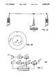
- a portable unit 101is a distance D1 from an antenna with a local base station 103.
- Another portable unit 107is a distance D2 from the base station 103, where D1 is significantly greater than D2.
- a system controller 105is connected to the base station 103 to control communications in the system, as well understood in the art. Communications can occur directly from one unit 101 to the other unit 107 if the units are close enough, or indirectly when one unit 101 transmits to the base station 103 which repeats the message to the other unit 107, as is known in the art.
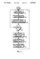
- FIG. 2a block diagram of a portable unit (200) is shown that performs the operations in the flowcharts of FIG. 3 and FIG. 4. Although a digital radio is shown, application of this invention to an analog radio will remain successful.
- This unit 200includes generally a microphone 201 for receiving an audible voice message to be transmitted, and for providing a push-to-talk (PTT) signal to a host computer 207, such as an MC68HC11 microprocessor, available from Motorola, Inc., the latter being in accordance with well understood prior art technique.
- a host computer 207such as an MC68HC11 microprocessor, available from Motorola, Inc., the latter being in accordance with well understood prior art technique.
- the DSP 205produces as its output a plurality of discrete packets, wherein each packet contains information representing a portion of the original speech information. These packets are provided to an appropriate radio frequency (RF) unit 209, which uses the packet information to modulate an appropriate carrier signal, which carrier signal is then radiated from an appropriate antenna 211, all as known in the art.
- RFradio frequency
- the receiver portion of the portable communication unituses the antenna 211 for receiving the carrier signal and the receive section of the RF unit 209 for receiving this signal and demodulating it to retrieve the discrete packets as sourced by the transmitter.
- These recovered packetsare provided to the DSP 205 that has been appropriately programmed to reconstruct the original voice information based upon the voice packet information.
- These packetshave interleaved therewith signalling information, including the bits of a selected error-control coding scheme.
- the DSP 205provides the latter information to the microprocessor 207.
- the output of the DSP 205comprises a digitized representation of the original voice message. This output passes through an appropriate digital to analog converter 213 and then to a power amplifier 215. The latter amplifies the reconstructed analog voice information, and a speaker 217 then renders this information audible.
- a portable communication unit(“first unit”) 101 of FIG. 1 receives or waits to receive a possible message from another communication unit (“second unit”), either a base station 103 or another portable 107.
- the first unitmeasures a signal quality metric, SI, of any message received at step 301.
- This signal quality metricincludes values of bit error rate (BER) measurements, received signal strength measurements (RSS), or other such measurements, as are well known in the art.
- BERbit error rate
- RSSreceived signal strength measurements
- Included in the message received at step 301should be a receive quality metric, RI, from the second unit.
- This receive quality metricis established by the second unit based on the reception of the message previously transmitted by the first unit 101 and includes, for example, values of BER measurements, received signal strength measurements, error detection indications, and so forth.
- the first unit 101receives and then stores the receive quality metric established by the second unit 103 or 107.
- step 307the process continues with step 301. If at step 307 the PTT on the first unit is asserted, the first unit determines, according to the steps in the flowchart of FIG. 4, the first unit's transmit power level from TI (the time of the previous transmission by the first unit 101), RI, PI (the power level of the previous transmission), and the current time T at step 309.
- the first unittransmits at step 311 at the transmit power level PI determined in step 309 and stores the transmit time as time value TI.
- the first unit 101includes in its transmission the signal quality metric, SI, measured in step 303.
- a further enhancement to this procedureincludes transmission of a brief test signal to obtain a more current RI, TI, and SI for the next message transmission.
- a brief test signal transmitted immediately before the message of interestcauses the current channel conditions to be known to the transmitting unit. This procedure drains little power since it is milliseconds in duration, but provides valuable information to insure that the desired communication is received with minimal interference.
- a flowchart showing determination of transmit power levelis set forth in FIG. 4, as is performed by the portable unit (first unit) in step 309. If at step 401, TI-T is greater than TMAX (a predetermined value stored in the unit that reflects a maximum time period between communications in which the power level is not adjusted due to time considerations) the process continues with step 403. (As a further enhancement, the unit may also select to consider TI-T greater than TMAX if an RI value is not received from the other unit within a certain time.) Time between successive transmissions is considered when selecting the power level because a portable unit may have travelled a significant distance between transmissions, e.g., if the operator goes to lunch, hence the quality metric data will not reflect the current situation of the unit. Likewise, the channel may be subject to various changes over long time spans, such as weather or heavy traffic in other systems, that may adversely affect a transmission if not accounted for.
- TMAXa predetermined value stored in the unit that reflects a maximum time
- the unitselects for the transmit power level PI the initial power level of the radio, PINIT, as stored in the unit.
- PINITmay be the maximum power level at which the unit can transmit, or it may be a lower level chosen to minimize power consumption based on average required power level in the system. In the preferred embodiment, PINIT is half of the maximum power capability of the portable unit. If at step 401 TI-T is not greater than TMAX, the process continues with step 405. At step 405, ⁇ P is determined from the curve of FIG. 5 based on the value of RI, where RMIN is a predetermined value or set of values of minimum acceptable receive quality metric.
- PIis found by taking the previous value of PI and adding ⁇ P to produce the transmit power level, and the process ends. In this fashion, the lowest transmit power level is chosen which gives acceptable values for signal quality metric, receive quality metric, and time between transmissions.
- RImay represent BER or RSS, as optimized for the particular system.
- the graphshows a decreasing function for RI less than predetermined value RMIN, a flat line for RMIN ⁇ RI ⁇ RMAX, and a further decreasing function for RI greater than predetermined value RMAX.
- RMIN and RMAXare optimized for the system, where the values RMIN ⁇ RI ⁇ RMAX reflect acceptable receive quality metric values.
- ⁇ Pis a negative value, resulting in the transmit power level being decreased, hence a savings in battery consumption is realized.
- ⁇ PWhen RI is less than RMIN, indicating that the receive quality metric is bad, i.e., less than acceptable, ⁇ P is a positive value, resulting in the power level being increased to maintain good reception of communications. Values for ⁇ P are optimized to reflect system performance and account for the minimum and maximum transmit power level of the portable unit.
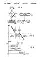
- FIG. 6a graph shows received signal strength versus bit error rate.
- FIG. 6combines RSS and BER to determine ⁇ P.
- FIG. 6shows a first contour 601, above and to the left of which the signal quality is good, and negative ⁇ P is realized, allowing for the best opportunity to saving battery charge.
- the first contour 601is defined by a maximum BER, e.g., 1% BER, and a minimum RSS, e.g., -60 dBm.
- One or more negative ⁇ P valuesmay be assigned in order to minimize power consumption and maximize receive quality.
- FIG. 6also shows a second contour 603, below and to the right of which the signal quality is bad, and positive ⁇ P is realized, not allowing for the opportunity to save battery charge.
- the second contour 603is defined by a minimum BER, e.g., 5% BER, and a maximum RSS, e.g., -90 dBm.
- Values for ⁇ P in FIG. 6are also optimized to reflect system performance and account for the minimum and maximum transmit power level of the portable unit.
- Receive quality metricsare measured and exchanged between a portable communication unit and another communication unit to allow a portable communication unit to transmit at lower transmit power levels, thus providing battery savings that extends battery usage time in a portable unit without use of an additional channel.
- a portable unit 101may also engage in indirect communications with another unit 107, through a base station or repeater 103, as shown in FIG. 1B.
- the portable unit 101transmits a message 701, as shown in FIG. 7, on a first communication channel to a repeater 103.
- the repeater 103receives the message 701 on the first channel and repeats the message 703 on a second communication channel.
- the message 701may contain an end-of-message marker at the end of the message, to notify receiving devices, such as repeaters or other communication units, that there is no more message information to be transmitted.
- the repeater 103While receiving the message 701 from the portable unit 101, the repeater 103 establishes a receive quality metric on the message 701, as previously described. The repeater 103 transmits the receive quality metric (RQM) 705 after all the message has been repeated.
- RQMreceive quality metric
- end of message (EOM) informationmay be transmitted after the receive quality metric 705 is transmitted, but such information is not necessary to practice the present invention.
- EOMend of message
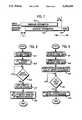
- FIG. 8A flowchart showing communication unit operation when obtaining a receive quality metric is shown in FIG. 8.
- the portable unit 101determines its transmit power at step 801 and transmits a message 701 on a first channel at that power at step 803.
- the unittunes to a second, or receive, channel at step 807, where the unit receives and stores a receive quality metric 705 from the end of the repeated message at step 809, and the procedure ends.
- FIG. 9A flowchart showing repeater operation when providing a receive quality metric is shown in FIG. 9.
- the repeater 103receives the message 701 from the unit 101 at step 901.
- the repeater 103repeats the message 703 at step 903.
- the repeaterestablishes a receive quality metric of the message 701 at step 905.
- the repeater 103receives (rx) the end of the message (EOM) from the unit at step 907
- the repeater 103transmits the receive quality metric 705 after the message 703 is transmitted at step 909, and the procedure ends.
- the present inventionallows for receipt of a receive quality metric without using an additional channel or transmitting an additional message to the unit. Hence, economy of channel usage and transmission time is achieved while providing the advantage of having signal quality measurements substantially immediately after a message is transmitted by the portable unit 101.
Landscapes
- Engineering & Computer Science (AREA)
- Computer Networks & Wireless Communication (AREA)
- Signal Processing (AREA)
- Mobile Radio Communication Systems (AREA)
Abstract
Description
This is a continuation-in-part of application Ser. No. 07/743,539, filed Aug. 9, 1991 and now abandoned.
This invention relates to battery saving mechanisms, including but not limited to battery saving functions for a portable transceiver in a digital communication system.
RF communications exist. These communications incorporate portable communication units ("portables") that are powered by rechargeable batteries to enable communications in various locations without requiring an external power supply. Unfortunately, after several hours of use, the battery discharges and must be recharged or replaced with a charged battery.
Several techniques for providing a battery-saving system for portables are known. One such system employs a push-to-talk (PTT) circuit wherein the transmitter of the portable is manually keyed by a push button or the like when it is desired to transmit a message, the transmitter normally being unkeyed when no message is being transmitted. Full-duplex systems may utilize voice activation circuits to key the transmitter only while the user is speaking. Other systems apply synchronization codes and tone codes to enable the unit to operate in a low-power consumption mode when not engaged in a call.
In full-duplex cellular systems, cellular telephones adjust their transmit power level continuously in response to commands from the infrastructure. By reducing the transmitter whenever possible in this way, battery charge is conserved. These power-level commands are received on a separate dedicated supervisory channel. In many conventional communications systems, communication channels are a sparse commodity, and the use of a dedicated channel to convey power-level commands is too expensive a price to pay for battery savings in a portable.
Accordingly, a method of providing battery savings that extends battery usage time in a portable unit without use of an additional channel is desired.
FIG. 1A is a block diagram of a communications system in accordance with the invention.
FIG. 1B is a block diagram of a top plan representative view of a communications system in accordance with the invention.
FIG. 2 is a block diagram of a portable communication unit in accordance with the invention.
FIG. 3 is a flowchart showing transmission of a message with transmit power level determined in accordance with the invention.
FIG. 4 is a flowchart showing determination of transmit power level in accordance with the invention.
FIG. 5 is a graph showing power level change versus receive quality metric in accordance with the invention.
FIG. 6 is a graph showing received signal strength versus bit error rate in accordance with the invention.
FIG. 7 is a timing diagram showing a repeated message and appending of a receive quality metric in accordance with the invention.
FIG. 8 is a flowchart showing communication unit operation when obtaining a receive quality metric in accordance with the invention.
FIG. 9 is a flowchart showing repeater operation when providing a receive quality metric in accordance with the invention.
The following describes a communication protocol that provides battery savings in a portable unit. Based on communications between a portable communication unit, such as a portable radio, and another communication unit, such as a base station or another portable radio, information is developed and exchanged allowing the portable to transmit at a lower transmit power level based on signal quality measurements by both units. Hence, the transmitter is keyed at a lower power level, thus using less current and saving precious battery charge.
In this system, information is relayed between communication units. In FIG. 1A, aportable unit 101 is a distance D1 from an antenna with alocal base station 103. Anotherportable unit 107 is a distance D2 from thebase station 103, where D1 is significantly greater than D2. Asystem controller 105 is connected to thebase station 103 to control communications in the system, as well understood in the art. Communications can occur directly from oneunit 101 to theother unit 107 if the units are close enough, or indirectly when oneunit 101 transmits to thebase station 103 which repeats the message to theother unit 107, as is known in the art.
Referring now to FIG. 1B, portable 107 is closer to thebase station 103 than is portable 101. Contour C1 encloses an area covered by thebase station 103 where strong signal communication is possible between thebase station 103 and units located within this area. The area between contour C1 and contour C2 encloses an area covered by thebase station 103 where weak signal communication is possible between thebase station 103 and units located in the latter area. Although only two contours are shown for this system, the concepts taught by the present invention are readily extended to three or more contours, using bit error rates and/or received signal strength values to define the boundaries of the contours.
Referring now to FIG. 2, a block diagram of a portable unit (200) is shown that performs the operations in the flowcharts of FIG. 3 and FIG. 4. Although a digital radio is shown, application of this invention to an analog radio will remain successful. Thisunit 200 includes generally amicrophone 201 for receiving an audible voice message to be transmitted, and for providing a push-to-talk (PTT) signal to ahost computer 207, such as an MC68HC11 microprocessor, available from Motorola, Inc., the latter being in accordance with well understood prior art technique. The transduced output of themicrophone 201 comprises an analog signal representing the voice input, and passes through an appropriate analog todigital converter 203, which digitizes this information and provides the digital representation to a digital signal processor (DSP) 205, such as a DSP56000 available from Motorola, Inc. The DSP 205 is programmed as appropriate to effectuate a desired voice encoding methodology.
The DSP 205 produces as its output a plurality of discrete packets, wherein each packet contains information representing a portion of the original speech information. These packets are provided to an appropriate radio frequency (RF)unit 209, which uses the packet information to modulate an appropriate carrier signal, which carrier signal is then radiated from anappropriate antenna 211, all as known in the art.
Both the DSP 205 and theRF unit 209 are controlled, at least in part, by thehost computer 207. In particular, so configured, thehost 207 detects conclusion of a voice message by detecting appropriate manipulation of the PTT switch on themicrophone 201. In response thereto, themicroprocessor 207 signals theRF unit 209 to terminate transmission activity.
The receiver portion of the portable communication unit uses theantenna 211 for receiving the carrier signal and the receive section of theRF unit 209 for receiving this signal and demodulating it to retrieve the discrete packets as sourced by the transmitter. These recovered packets are provided to the DSP 205 that has been appropriately programmed to reconstruct the original voice information based upon the voice packet information. These packets have interleaved therewith signalling information, including the bits of a selected error-control coding scheme. The DSP 205 provides the latter information to themicroprocessor 207.
The output of the DSP 205 comprises a digitized representation of the original voice message. This output passes through an appropriate digital toanalog converter 213 and then to apower amplifier 215. The latter amplifies the reconstructed analog voice information, and aspeaker 217 then renders this information audible.
Transmission of a message with transmit power level determined in accordance with the invention is shown in the flowchart of FIG. 3. Atstep 301, a portable communication unit ("first unit") 101 of FIG. 1 receives or waits to receive a possible message from another communication unit ("second unit"), either abase station 103 or another portable 107. Atstep 303, the first unit measures a signal quality metric, SI, of any message received atstep 301. This signal quality metric includes values of bit error rate (BER) measurements, received signal strength measurements (RSS), or other such measurements, as are well known in the art. Included in the message received atstep 301 should be a receive quality metric, RI, from the second unit. This receive quality metric is established by the second unit based on the reception of the message previously transmitted by thefirst unit 101 and includes, for example, values of BER measurements, received signal strength measurements, error detection indications, and so forth. Atstep 305, thefirst unit 101 receives and then stores the receive quality metric established by thesecond unit
If atstep 307 the PTT on the first unit is not asserted, the process continues withstep 301. If atstep 307 the PTT on the first unit is asserted, the first unit determines, according to the steps in the flowchart of FIG. 4, the first unit's transmit power level from TI (the time of the previous transmission by the first unit 101), RI, PI (the power level of the previous transmission), and the current time T atstep 309.
The first unit transmits atstep 311 at the transmit power level PI determined instep 309 and stores the transmit time as time value TI. Atstep 313, thefirst unit 101 includes in its transmission the signal quality metric, SI, measured instep 303.
A further enhancement to this procedure includes transmission of a brief test signal to obtain a more current RI, TI, and SI for the next message transmission. A brief test signal transmitted immediately before the message of interest causes the current channel conditions to be known to the transmitting unit. This procedure drains little power since it is milliseconds in duration, but provides valuable information to insure that the desired communication is received with minimal interference.
A flowchart showing determination of transmit power level is set forth in FIG. 4, as is performed by the portable unit (first unit) instep 309. If atstep 401, TI-T is greater than TMAX (a predetermined value stored in the unit that reflects a maximum time period between communications in which the power level is not adjusted due to time considerations) the process continues withstep 403. (As a further enhancement, the unit may also select to consider TI-T greater than TMAX if an RI value is not received from the other unit within a certain time.) Time between successive transmissions is considered when selecting the power level because a portable unit may have travelled a significant distance between transmissions, e.g., if the operator goes to lunch, hence the quality metric data will not reflect the current situation of the unit. Likewise, the channel may be subject to various changes over long time spans, such as weather or heavy traffic in other systems, that may adversely affect a transmission if not accounted for.
Atstep 403, the unit selects for the transmit power level PI the initial power level of the radio, PINIT, as stored in the unit. The value of PINIT may be the maximum power level at which the unit can transmit, or it may be a lower level chosen to minimize power consumption based on average required power level in the system. In the preferred embodiment, PINIT is half of the maximum power capability of the portable unit. If atstep 401 TI-T is not greater than TMAX, the process continues withstep 405. Atstep 405, ΔP is determined from the curve of FIG. 5 based on the value of RI, where RMIN is a predetermined value or set of values of minimum acceptable receive quality metric. Atstep 407, PI is found by taking the previous value of PI and adding ΔP to produce the transmit power level, and the process ends. In this fashion, the lowest transmit power level is chosen which gives acceptable values for signal quality metric, receive quality metric, and time between transmissions.
Referring now to FIG. 5, a graph showing power level change versus receive quality metric is shown. RI may represent BER or RSS, as optimized for the particular system. The graph shows a decreasing function for RI less than predetermined value RMIN, a flat line for RMIN≦RI≦RMAX, and a further decreasing function for RI greater than predetermined value RMAX. The values of RMIN and RMAX are optimized for the system, where the values RMIN≦RI≦RMAX reflect acceptable receive quality metric values. When RI is greater than RMAX, indicating that the receive quality metric is good, i.e., better than acceptable, ΔP is a negative value, resulting in the transmit power level being decreased, hence a savings in battery consumption is realized. When RI is less than RMIN, indicating that the receive quality metric is bad, i.e., less than acceptable, ΔP is a positive value, resulting in the power level being increased to maintain good reception of communications. Values for ΔP are optimized to reflect system performance and account for the minimum and maximum transmit power level of the portable unit.
Referring now to FIG. 6, a graph shows received signal strength versus bit error rate. As a further enhancement of the graph in FIG. 5, FIG. 6 combines RSS and BER to determine ΔP. FIG. 6 shows afirst contour 601, above and to the left of which the signal quality is good, and negative ΔP is realized, allowing for the best opportunity to saving battery charge. Thefirst contour 601 is defined by a maximum BER, e.g., 1% BER, and a minimum RSS, e.g., -60 dBm. One or more negative ΔP values may be assigned in order to minimize power consumption and maximize receive quality. For example, if BER<0.1% and RSS>-40 dBm, ΔP may be assigned the value -5 dB, and all other values between these BER and RSS values and 1% BER and RSS=-60 dBm would reflect a ΔP of -1 dB.
FIG. 6 also shows asecond contour 603, below and to the right of which the signal quality is bad, and positive ΔP is realized, not allowing for the opportunity to save battery charge. Thesecond contour 603 is defined by a minimum BER, e.g., 5% BER, and a maximum RSS, e.g., -90 dBm. One or more positive ΔP values may be assigned in order to minimize power consumption and maximize receive quality. For example, if BER<10% and RSS>-110 dBm, ΔP may be assigned the maximum ΔP value, e.g. +10 dB, and all other values between these BER and RSS values and 5% BER and RSS=-90 dBm would reflect a ΔP of +1 dB.
Values for ΔP in FIG. 6 are also optimized to reflect system performance and account for the minimum and maximum transmit power level of the portable unit.
Receive quality metrics are measured and exchanged between a portable communication unit and another communication unit to allow a portable communication unit to transmit at lower transmit power levels, thus providing battery savings that extends battery usage time in a portable unit without use of an additional channel.
In addition to direct portable-to-portable communications, aportable unit 101 may also engage in indirect communications with anotherunit 107, through a base station orrepeater 103, as shown in FIG. 1B. When engaged in such indirect communications, theportable unit 101 transmits amessage 701, as shown in FIG. 7, on a first communication channel to arepeater 103. Therepeater 103 receives themessage 701 on the first channel and repeats themessage 703 on a second communication channel. Themessage 701 may contain an end-of-message marker at the end of the message, to notify receiving devices, such as repeaters or other communication units, that there is no more message information to be transmitted. Because of the inherent delay between transmitting and receiving themessage 701, and if necessary buffering themessage 701 to provide any detection, reliability measurement, or other such analysis, there is a time delay between the transmission of themessage 701 by theunit 101 at a first time and the repeated transmission of themessage 703 by therepeater 103 at a second time. The time between the first time and the second time is the delay time, TD. While receiving themessage 701 from theportable unit 101, therepeater 103 establishes a receive quality metric on themessage 701, as previously described. Therepeater 103 transmits the receive quality metric (RQM) 705 after all the message has been repeated. If the system so provides, end of message (EOM) information may be transmitted after the receivequality metric 705 is transmitted, but such information is not necessary to practice the present invention. Once theportable unit 101 has completed transmission of the message, it has the amount of time, TD, to tune its receiver to the second communication channel so that it may receive the receive quality metric 705 as transmitted by therepeater 103 after the repeatedmessage 703.
A flowchart showing communication unit operation when obtaining a receive quality metric is shown in FIG. 8. Theportable unit 101 determines its transmit power atstep 801 and transmits amessage 701 on a first channel at that power atstep 803. When the unit is done transmitting (xmitting) themessage 701 atstep 805, theunit 101 tunes to a second, or receive, channel atstep 807, where the unit receives and stores a receive quality metric 705 from the end of the repeated message atstep 809, and the procedure ends.
A flowchart showing repeater operation when providing a receive quality metric is shown in FIG. 9. Therepeater 103 receives themessage 701 from theunit 101 atstep 901. Therepeater 103 repeats themessage 703 atstep 903. The repeater establishes a receive quality metric of themessage 701 atstep 905. When therepeater 103 receives (rx) the end of the message (EOM) from the unit atstep 907, therepeater 103 transmits the receivequality metric 705 after themessage 703 is transmitted atstep 909, and the procedure ends.
Thus, by providing the receive quality metric 705 at the end of the repeated message, the present invention allows for receipt of a receive quality metric without using an additional channel or transmitting an additional message to the unit. Hence, economy of channel usage and transmission time is achieved while providing the advantage of having signal quality measurements substantially immediately after a message is transmitted by theportable unit 101.
Claims (20)
1. A method of reducing power consumption in a portable communication unit, comprising the steps of:
transmitting at a first time, by the portable communication unit, a first message at a first transmit power level to a repeater on a first communication channel;
repeating at a second time, which second time is later than said first time, by said repeater, said first message, thereby transmitting a delayed message on a second communication channel;
tuning the portable communication unit to said second communication channel after transmitting all of said first message, so as to receive at least part of said delayed message;
establishing a receive quality metric for said first message at said repeater;
transmitting said receive quality metric appended to the end of said delayed message after all of said delayed message has been repeated;
receiving and storing in the portable communication unit said receive quality metric; and
determining, by the portable communication unit, a second transmit power level for transmitting a second message, said determining step using said stored receive quality metric.
2. The method of claim 1, wherein said determining step further comprises the steps of:
computing a time value from transmission of said first message to transmission of said second message; and
setting said second transmit power level to an initial power level when said time value has a first relationship with respect to a predetermined value.
3. The method of claim 1, wherein said receive quality metric represents a bit error rate measurement and wherein said determining step further comprises the step of decreasing said first transmit power level to produce said second transmit power level when said bit error rate measurement has a first relationship with respect to a predetermined value.
4. The method of claim 1, wherein said receive quality metric represents a bit error rate measurement and wherein said determining step further comprises the step of increasing said first transmit power level to produce said second transmit power level when said bit error rate measurement has a second relationship with respect to a predetermined value.
5. The method of claim 1, wherein said receive quality metric represents a received signal strength measurement and wherein said determining step further comprises the step of decreasing said first transmit power level to produce said second transmit power level when said received signal strength measurement has a first relationship with respect to a predetermined value.
6. The method of claim 1, wherein said receive quality metric represents a received signal strength measurement and wherein said determining step further comprises the step of increasing said first transmit power level to produce said second transmit power level when said received signal strength measurement has a second relationship with respect to a predetermined value.
7. The method of claim 1, further comprising the steps of:
computing a signal quality metric for said receive quality metric; and
decreasing said second transmit power level when said receive quality metric has a first relationship with respect to a predetermined value.
8. The method of claim 1, further comprising the steps of:
computing a signal quality metric for said receive quality metric; and
increasing said second transmit power level when said receive quality metric has a second relationship with respect to a predetermined value.
9. The method of claim 1, wherein said receive quality metric represents a bit error rate measurement and a received signal strength measurement and wherein said determining step further comprises the step of decreasing said first transmit power level to produce said second transmit power level when said bit error rate measurement has a first relationship with respect to a first predetermined value and said received signal strength measurement has said first relationship with respect to a second predetermined value.
10. The method of claim 1, wherein said receive quality metric represents a bit error rate measurement and a received signal strength measurement and wherein said determining step further comprises the step of increasing said first transmit power level to produce said second transmit power level when said bit error rate measurement has a second relationship with respect to a first predetermined value and said received signal strength measurement has said second relationship with respect to a second predetermined value.
11. A portable communication unit, comprising:
means for transmitting at a first time a first message at a first transmit power level to a repeater on a first communication channel;
means for tuning to a second communication channel after transmitting all of said first message, so as to receive at least part of a delayed message, which is comprised of said first message transmitted at a second time on said second communication channel;
means for receiving a receive quality metric from said repeater, wherein said receive quality metric, appended to the end of said delayed message, is transmitted after all of said first message is transmitted;
means for storing said receive quality metric; and
means, coupled to said means for storing, for determining a second transmit power level for transmitting a second message, said determining means using said receive quality metric.
12. The portable communication unit of claim 11, wherein said means for determining comprises:
means for computing a time value from transmission of said first message to transmission of said second message; and
means for setting said second transmit power level to an initial power level when said time value has a first relationship with respect to a predetermined value.
13. The portable communication unit of claim 11, wherein said receive quality metric represents a bit error rate measurement and wherein said determining means further comprises means for decreasing said first transmit power level to produce said second transmit power level when said bit error rate measurement has a first relationship with respect to a predetermined value.
14. The portable communication unit of claim 11, wherein said receive quality metric represents a bit error rate measurement and wherein said determining means further comprises means for increasing said first transmit power level to produce said second transmit power level when said bit error rate measurement has a second relationship with respect to a predetermined value.
15. The portable communication unit of claim 11, wherein said receive quality metric represents a received signal strength measurement and wherein said determining means further comprises means for decreasing said first transmit power level to produce said second transmit power level when said received signal strength measurement has a first relationship with respect to a predetermined value.
16. The portable communication unit of claim 11, wherein said receive quality metric represents a received signal strength measurement and wherein said determining means further comprises means for increasing said first transmit power level to produce said second transmit power level when said received signal strength measurement has a second relationship with respect to a predetermined value.
17. The portable communication unit of claim 11, further comprising:
means for computing a signal quality metric for said received receive quality metric; and
means for decreasing said second transmit power level when said receive quality metric has a first relationship with respect to a predetermined value.
18. The portable communication unit of claim 11, further comprising:
means for computing a signal quality metric for said received receive quality metric; and
means for increasing said second transmit power level when said receive quality metric has a second relationship with respect to a predetermined value.
19. The portable communication unit of claim 11, wherein said receive quality metric represents a bit error rate measurement and a received signal strength measurement and wherein said determining means further comprises means for decreasing said first transmit power level to produce said second transmit power level when said bit error rate measurement has a first relationship with respect to a first predetermined value and said received signal strength measurement has said first relationship with respect to a second predetermined value.
20. The portable communication unit of claim 11, wherein said receive quality metric represents a bit error rate measurement and a received signal strength measurement and wherein said determining means further comprises means for increasing said first transmit power level to produce said second transmit power level when said bit error rate measurement has a second relationship with respect to a first predetermined value and said received signal strength measurement has said second relationship with respect to a second predetermined value.
Priority Applications (1)
| Application Number | Priority Date | Filing Date | Title |
|---|---|---|---|
| US08/028,530US5293639A (en) | 1991-08-09 | 1993-03-09 | Reduction of power consumption in a portable communication unit |
Applications Claiming Priority (2)
| Application Number | Priority Date | Filing Date | Title |
|---|---|---|---|
| US74353991A | 1991-08-09 | 1991-08-09 | |
| US08/028,530US5293639A (en) | 1991-08-09 | 1993-03-09 | Reduction of power consumption in a portable communication unit |
Related Parent Applications (1)
| Application Number | Title | Priority Date | Filing Date |
|---|---|---|---|
| US74353991AContinuation-In-Part | 1991-08-09 | 1991-08-09 |
Publications (1)
| Publication Number | Publication Date |
|---|---|
| US5293639Atrue US5293639A (en) | 1994-03-08 |
Family
ID=26703803
Family Applications (1)
| Application Number | Title | Priority Date | Filing Date |
|---|---|---|---|
| US08/028,530Expired - LifetimeUS5293639A (en) | 1991-08-09 | 1993-03-09 | Reduction of power consumption in a portable communication unit |
Country Status (1)
| Country | Link |
|---|---|
| US (1) | US5293639A (en) |
Cited By (75)
| Publication number | Priority date | Publication date | Assignee | Title |
|---|---|---|---|---|
| US5446756A (en)* | 1990-03-19 | 1995-08-29 | Celsat America, Inc. | Integrated cellular communications system |
| US5471655A (en)* | 1993-12-03 | 1995-11-28 | Nokia Mobile Phones Ltd. | Method and apparatus for operating a radiotelephone in an extended stand-by mode of operation for conserving battery power |
| US5487180A (en)* | 1993-09-20 | 1996-01-23 | Fujitsu Limited | Method of determining initial transmission power |
| US5490288A (en)* | 1994-02-08 | 1996-02-06 | Motorola, Inc. | Method for determining low signal quality communications |
| US5655219A (en)* | 1993-03-05 | 1997-08-05 | Hitachi, Ltd. | Wireless LAN system capable of re-transmission under management of a base station device to a destination mobile terminal device |
| US5669064A (en)* | 1994-03-17 | 1997-09-16 | Fujitsu Limited | Mobile method and apparatus for standby control in a communication system |
| US5710981A (en)* | 1995-05-23 | 1998-01-20 | Ericsson Inc. | Portable radio power control device and method using incrementally degraded received signals |
| US5722051A (en)* | 1996-02-13 | 1998-02-24 | Lucent Technologies Inc. | Adaptive power control and coding scheme for mobile radio systems |
| US5745842A (en)* | 1995-05-18 | 1998-04-28 | Ericsson Inc. | Method and apparatus for controlling operation of a portable or mobile battery-operated radios |
| US5752201A (en)* | 1996-02-09 | 1998-05-12 | Nokia Mobile Phones Limited | Mobile terminal having power saving mode that monitors specified numbers of filler messages |
| US5765114A (en)* | 1994-03-23 | 1998-06-09 | Mitsubishi Denki Kabushiki Kaisha | Communication apparatus with reduced redundant data receipt and method for receiving data |
| WO1998025324A1 (en)* | 1996-12-06 | 1998-06-11 | Motorola Inc. | Method for a transceiver to select a channel |
| US6032050A (en)* | 1994-05-20 | 2000-02-29 | Fujitsu Limited | Method for standby control in a mobile telecommunications network setting standby conditions conforming to different modes of communication and mobile unit using same |
| US6067460A (en)* | 1996-05-23 | 2000-05-23 | Nokia Mobile Phones Limited | Mobile station having enhanced standby mode |
| US6240304B1 (en) | 1998-02-11 | 2001-05-29 | Nokia Mobile Phones Ltd. | Mobile terminal having RF power consumption optimization of extended standby mode |
| US6282430B1 (en) | 1999-01-01 | 2001-08-28 | Motorola, Inc. | Method for obtaining control information during a communication session in a radio communication system |
| US20010021650A1 (en)* | 1997-03-20 | 2001-09-13 | Bilgic Izzet M. | Communication control for a user of a central communication center |
| WO2002005578A1 (en)* | 2000-07-12 | 2002-01-17 | Symbol Technologies, Inc. | Method and apparatus for variable power control in wireless communications systems |
| WO2001078291A3 (en)* | 2000-04-07 | 2002-05-10 | Ericsson Telefon Ab L M | System and method for data burst communications in a cdma network |
| US20020130692A1 (en)* | 1999-06-28 | 2002-09-19 | Broadcom Corporation | Current-controlled CMOS logic family |
| US20030051080A1 (en)* | 1991-10-01 | 2003-03-13 | Mahany Ronald L. | Radio frequency local area network |
| US20030067337A1 (en)* | 1999-06-28 | 2003-04-10 | Broadcom Corporation | Current-controlled CMOS circuit using higher voltage supply in low voltage CMOS process |
| US20030078006A1 (en)* | 1988-08-04 | 2003-04-24 | Mahany Ronald L. | Remote radio data communication system with data rate switching |
| US20030112767A1 (en)* | 1991-10-01 | 2003-06-19 | Meier Robert C. | Communication network providing wireless and hard-wired dynamic routing |
| US20030122603A1 (en)* | 2000-02-24 | 2003-07-03 | Broadcom Corporation | Current-controlled CMOS circuits with inductive broadbanding |
| US20030142652A1 (en)* | 2002-01-29 | 2003-07-31 | Palm, Inc. | Dynamic networking modes method and apparatus |
| US20030174764A1 (en)* | 1989-08-03 | 2003-09-18 | Mahany Ronald L. | Radio frequency communication network having adaptive communication parameters |
| US20040023651A1 (en)* | 1991-05-13 | 2004-02-05 | Gollnick Charles D. | Network supporting roaming, sleeping terminals |
| US20040056717A1 (en)* | 2001-10-25 | 2004-03-25 | Broadcom Corporation | Current-controlled CMOS wideband data amplifier circuits |
| US6802033B1 (en) | 1999-04-06 | 2004-10-05 | International Business Machines Corporation | Low-power critical error rate communications controller |
| US20040207040A1 (en)* | 2001-05-17 | 2004-10-21 | Broadcom Corporation | Layout technique for C3MOS inductive broadbanding |
| US20040217777A1 (en)* | 1999-06-28 | 2004-11-04 | Armond Hairapetian | Universal single-ended parallel bus |
| US20040224631A1 (en)* | 2003-05-08 | 2004-11-11 | M/A Com. Inc. | Activiation method for wireless communication system |
| US20040227544A1 (en)* | 1999-06-28 | 2004-11-18 | Guangming Yin | Current-controlled CMOS circuit using higher voltage supply in low voltage CMOS process |
| US6826165B1 (en) | 1991-10-01 | 2004-11-30 | Broadcom Corporation | Radio frequency local area network |
| US20050215237A1 (en)* | 2004-03-24 | 2005-09-29 | Carrier Corporation | Method of setting the output power of a pager to aid in the installation of a wireless system |
| EP1734666A1 (en)* | 2005-06-17 | 2006-12-20 | Fujitsu Limited | Resource management in multi-hop communication system |
| EP1734668A1 (en)* | 2005-06-17 | 2006-12-20 | Fujitsu Limited | Power control in multi-hop communication system |
| EP1734664A1 (en)* | 2005-06-17 | 2006-12-20 | Fujitsu Limited | Power control in multi-hop communication system |
| US20070025435A1 (en)* | 2005-07-29 | 2007-02-01 | Jun Cao | Current-controlled CMOS (C3MOS) fully differential integrated wideband amplifier/equalizer with adjustable gain and frequency response without additional power or loading |
| US20070024369A1 (en)* | 2005-07-29 | 2007-02-01 | Jun Cao | Current-controlled CMOS (C3MOS) wideband input data amplifier for reduced differential and common-mode reflection |
| US20070052467A1 (en)* | 2005-09-06 | 2007-03-08 | Jun Cao | Current-controlled CMOS (C3MOS) fully differential integrated delay cell with variable delay and high bandwidth |
| US20070066241A1 (en)* | 2005-06-17 | 2007-03-22 | Hart Michael J | Communication system |
| US20070081075A1 (en)* | 2002-01-29 | 2007-04-12 | Palm, Inc. | Videoconferencing bandwidth management for a handheld computer system and method |
| US20070116106A1 (en)* | 2005-06-17 | 2007-05-24 | Hart Michael J | Communication system |
| US7224745B2 (en)* | 1999-11-19 | 2007-05-29 | Siemens Communications, Inc. | Method and system for power-conserving interference avoidance in communication between a mobile unit and a base unit in a wireless telecommunication system |
| US20070147308A1 (en)* | 2005-12-21 | 2007-06-28 | Hart Michael J | Signalling in multi-hop communication systems |
| US20070167149A1 (en)* | 2001-05-31 | 2007-07-19 | Palm, Inc. | System and method for communicating with a network access node |
| US20070163080A1 (en)* | 2002-01-29 | 2007-07-19 | Palm, Inc. | Replaceable cover for handheld computer |
| US20080025315A1 (en)* | 2002-03-08 | 2008-01-31 | Broadcom Corporation | System and method for identifying upper layer protocol message boundaries |
| US20080032738A1 (en)* | 2001-03-07 | 2008-02-07 | Palm, Inc. | Portable wireless network |
| US20080151922A1 (en)* | 2002-08-30 | 2008-06-26 | Uri Elzur | System and method for tcp offload |
| US7415548B2 (en) | 1991-05-13 | 2008-08-19 | Broadcom Corporation | Communication network having a plurality of bridging nodes which transmits a polling message with backward learning technique to determine communication pathway |
| US20080298369A1 (en)* | 2002-08-30 | 2008-12-04 | Uri Elzur | System and method for handling out-of-order frames |
| US20090074408A1 (en)* | 1997-01-23 | 2009-03-19 | Broadcom Corporation | Fibre channel arbitrated loop bufferless switch circuitry to increase bandwidth without significant increase in cost |
| US20090092070A1 (en)* | 1992-11-02 | 2009-04-09 | Broadcom Corporation | Radio frequency local area network |
| US20090219853A1 (en)* | 2004-03-02 | 2009-09-03 | Michael John Beems Hart | Wireless Communication Systems |
| US20090254647A1 (en)* | 2002-08-29 | 2009-10-08 | Uri Elzur | System and method for network interfacing |
| US20100002619A1 (en)* | 2006-10-02 | 2010-01-07 | Fujitsu Limited | Communication systems |
| US20100074164A1 (en)* | 2006-11-06 | 2010-03-25 | Fujitsu Limited | Communication Systems |
| US20100214992A1 (en)* | 2007-03-19 | 2010-08-26 | Michael John Beems Hart | Wireless Communication Systems |
| US20100250783A1 (en)* | 2002-08-30 | 2010-09-30 | Uri Elzur | System and method for tcp/ip offload independent of bandwidth delay product |
| US20110110236A1 (en)* | 2001-07-23 | 2011-05-12 | Shiri Kadambi | Multiple Logical Channels for Use in Network Devices |
| US8180928B2 (en) | 2002-08-30 | 2012-05-15 | Broadcom Corporation | Method and system for supporting read operations with CRC for iSCSI and iSCSI chimney |
| US8798091B2 (en) | 1998-11-19 | 2014-08-05 | Broadcom Corporation | Fibre channel arbitrated loop bufferless switch circuitry to increase bandwidth without significant increase in cost |
| US20140369211A1 (en)* | 2013-06-12 | 2014-12-18 | Honeywell International, Inc. | Apparatus and method for reporting of communication path quality within a wireless network |
| CN101366195B (en)* | 2006-02-08 | 2015-06-17 | 艾利森电话股份有限公司 | Energy consumption minimized link adaptation and power control |
| US9154996B2 (en) | 2013-06-12 | 2015-10-06 | Honeywell International Inc. | Apparatus and method for maintaining reliability of wireless network having asymmetric or other low quality wireless links |
| US9191237B1 (en)* | 2012-05-24 | 2015-11-17 | Dan Barry, Inc. | Wireless communication systems and methods |
| US9552056B1 (en) | 2011-08-27 | 2017-01-24 | Fellow Robots, Inc. | Gesture enabled telepresence robot and system |
| US9796093B2 (en) | 2014-10-24 | 2017-10-24 | Fellow, Inc. | Customer service robot and related systems and methods |
| US10311400B2 (en) | 2014-10-24 | 2019-06-04 | Fellow, Inc. | Intelligent service robot and related systems and methods |
| US10373116B2 (en) | 2014-10-24 | 2019-08-06 | Fellow, Inc. | Intelligent inventory management and related systems and methods |
| US10586082B1 (en) | 2019-05-29 | 2020-03-10 | Fellow, Inc. | Advanced micro-location of RFID tags in spatial environments |
| US20200267656A1 (en)* | 2018-08-20 | 2020-08-20 | Robert D. Fish | Mobile Target Locator with Both RF And Cellular Communications |
Citations (14)
| Publication number | Priority date | Publication date | Assignee | Title |
|---|---|---|---|---|
| US3962553A (en)* | 1973-03-29 | 1976-06-08 | Motorola, Inc. | Portable telephone system having a battery saver feature |
| US4181893A (en)* | 1975-06-26 | 1980-01-01 | Motorola, Inc. | Battery saver for a tone coded signalling system |
| US4309771A (en)* | 1979-07-02 | 1982-01-05 | Farinon Corporation | Digital radio transmission system |
| US4370753A (en)* | 1975-06-26 | 1983-01-25 | Motorola, Inc. | Battery saver for a tone coded signalling system |
| US4381552A (en)* | 1978-12-08 | 1983-04-26 | Motorola Inc. | Stanby mode controller utilizing microprocessor |
| US4398192A (en)* | 1981-12-04 | 1983-08-09 | Motorola Inc. | Battery-saving arrangement for pagers |
| US4613990A (en)* | 1984-06-25 | 1986-09-23 | At&T Bell Laboratories | Radiotelephone transmission power control |
| US4647793A (en)* | 1984-08-31 | 1987-03-03 | Motorola, Inc. | Driver circuit for generating output at two different levels |
| US4755816A (en)* | 1986-10-29 | 1988-07-05 | Motorola Inc. | Battery saving method for a selective call radio paging receiver |
| US4804954A (en)* | 1987-04-30 | 1989-02-14 | Motorola, Inc. | Battery saving method for portable communications receivers |
| US5001776A (en)* | 1988-10-27 | 1991-03-19 | Motorola Inc. | Communication system with adaptive transceivers to control intermodulation distortion |
| US5003619A (en)* | 1989-01-31 | 1991-03-26 | Motorola, Inc. | Method and apparatus for adjusting the power of a transmitter |
| US5204970A (en)* | 1991-01-31 | 1993-04-20 | Motorola, Inc. | Communication system capable of adjusting transmit power of a subscriber unit |
| US5220678A (en)* | 1991-08-12 | 1993-06-15 | Motorola, Inc. | Method and apparatus for adjusting the power of a transmitter |
- 1993
- 1993-03-09USUS08/028,530patent/US5293639A/ennot_activeExpired - Lifetime
Patent Citations (14)
| Publication number | Priority date | Publication date | Assignee | Title |
|---|---|---|---|---|
| US3962553A (en)* | 1973-03-29 | 1976-06-08 | Motorola, Inc. | Portable telephone system having a battery saver feature |
| US4181893A (en)* | 1975-06-26 | 1980-01-01 | Motorola, Inc. | Battery saver for a tone coded signalling system |
| US4370753A (en)* | 1975-06-26 | 1983-01-25 | Motorola, Inc. | Battery saver for a tone coded signalling system |
| US4381552A (en)* | 1978-12-08 | 1983-04-26 | Motorola Inc. | Stanby mode controller utilizing microprocessor |
| US4309771A (en)* | 1979-07-02 | 1982-01-05 | Farinon Corporation | Digital radio transmission system |
| US4398192A (en)* | 1981-12-04 | 1983-08-09 | Motorola Inc. | Battery-saving arrangement for pagers |
| US4613990A (en)* | 1984-06-25 | 1986-09-23 | At&T Bell Laboratories | Radiotelephone transmission power control |
| US4647793A (en)* | 1984-08-31 | 1987-03-03 | Motorola, Inc. | Driver circuit for generating output at two different levels |
| US4755816A (en)* | 1986-10-29 | 1988-07-05 | Motorola Inc. | Battery saving method for a selective call radio paging receiver |
| US4804954A (en)* | 1987-04-30 | 1989-02-14 | Motorola, Inc. | Battery saving method for portable communications receivers |
| US5001776A (en)* | 1988-10-27 | 1991-03-19 | Motorola Inc. | Communication system with adaptive transceivers to control intermodulation distortion |
| US5003619A (en)* | 1989-01-31 | 1991-03-26 | Motorola, Inc. | Method and apparatus for adjusting the power of a transmitter |
| US5204970A (en)* | 1991-01-31 | 1993-04-20 | Motorola, Inc. | Communication system capable of adjusting transmit power of a subscriber unit |
| US5220678A (en)* | 1991-08-12 | 1993-06-15 | Motorola, Inc. | Method and apparatus for adjusting the power of a transmitter |
Cited By (170)
| Publication number | Priority date | Publication date | Assignee | Title |
|---|---|---|---|---|
| US20030078006A1 (en)* | 1988-08-04 | 2003-04-24 | Mahany Ronald L. | Remote radio data communication system with data rate switching |
| US7606575B2 (en) | 1988-08-04 | 2009-10-20 | Broadcom Corporation | Remote radio data communication system with data rate switching |
| US7606287B2 (en) | 1989-08-03 | 2009-10-20 | Broadcom Corporation | Radio frequency communication network having adaptive communication parameters |
| US20030174764A1 (en)* | 1989-08-03 | 2003-09-18 | Mahany Ronald L. | Radio frequency communication network having adaptive communication parameters |
| US5446756A (en)* | 1990-03-19 | 1995-08-29 | Celsat America, Inc. | Integrated cellular communications system |
| US7415548B2 (en) | 1991-05-13 | 2008-08-19 | Broadcom Corporation | Communication network having a plurality of bridging nodes which transmits a polling message with backward learning technique to determine communication pathway |
| US7899951B2 (en) | 1991-05-13 | 2011-03-01 | Broadcom Corporation | Communication network having a plurality of bridging nodes which transmits a polling message with backward learning technique to determine communication pathway |
| US20040023651A1 (en)* | 1991-05-13 | 2004-02-05 | Gollnick Charles D. | Network supporting roaming, sleeping terminals |
| US20050086399A1 (en)* | 1991-05-13 | 2005-04-21 | Mahany Ronald L. | Radio frequency local area network |
| US7457646B2 (en) | 1991-05-13 | 2008-11-25 | Broadcom Corporation | Radio frequency local area network |
| US7552246B2 (en) | 1991-05-13 | 2009-06-23 | Broadcom Corporation | Communication network having a plurality of bridging nodes which transmit a beacon to terminal nodes in power saving state that it has messages awaiting delivery |
| US7536167B2 (en) | 1991-05-13 | 2009-05-19 | Broadcom Corporation | Network supporting roaming, sleeping terminals |
| US20070121529A1 (en)* | 1991-10-01 | 2007-05-31 | Broadcom Corporation | Communication network providing wireless and hard-wired dynamic routing |
| US20090247241A1 (en)* | 1991-10-01 | 2009-10-01 | Broadcom Corporation | Network supporting roaming, sleeping terminals |
| US20090172189A1 (en)* | 1991-10-01 | 2009-07-02 | Broadcom Corporation | Radio frequency local area network |
| US7873343B2 (en) | 1991-10-01 | 2011-01-18 | Broadcom Corporation | Communication network terminal with sleep capability |
| US20060268806A1 (en)* | 1991-10-01 | 2006-11-30 | Meier Robert C | Radio frequency local area network |
| US7633919B2 (en) | 1991-10-01 | 2009-12-15 | Broadcom Corporation | Communication network providing wireless and hard-wired dynamic routing |
| US6895450B2 (en) | 1991-10-01 | 2005-05-17 | Broadcom Corporation | Communication network having a plurality of bridging nodes which transmit a beacon to terminal nodes in power saving state that it has messages awaiting delivery |
| US20030051080A1 (en)* | 1991-10-01 | 2003-03-13 | Mahany Ronald L. | Radio frequency local area network |
| US20050078647A1 (en)* | 1991-10-01 | 2005-04-14 | Meier Robert C. | Radio frequency local area network |
| US6826165B1 (en) | 1991-10-01 | 2004-11-30 | Broadcom Corporation | Radio frequency local area network |
| US7483397B2 (en) | 1991-10-01 | 2009-01-27 | Broadcom Corporation | Radio frequency local area network |
| US7907577B2 (en) | 1991-10-01 | 2011-03-15 | Broadcom Corporation | Communication network providing wireless and hard-wired dynamic routing |
| US20030112767A1 (en)* | 1991-10-01 | 2003-06-19 | Meier Robert C. | Communication network providing wireless and hard-wired dynamic routing |
| US7558557B1 (en) | 1991-11-12 | 2009-07-07 | Broadcom Corporation | Low-power messaging in a network supporting roaming terminals |
| US20090092070A1 (en)* | 1992-11-02 | 2009-04-09 | Broadcom Corporation | Radio frequency local area network |
| US20090323589A1 (en)* | 1992-11-02 | 2009-12-31 | Broadcom Corporation | Radio frequency local area network |
| US7917145B2 (en) | 1992-11-02 | 2011-03-29 | Broadcom Corporation | Radio frequency local area network |
| US5655219A (en)* | 1993-03-05 | 1997-08-05 | Hitachi, Ltd. | Wireless LAN system capable of re-transmission under management of a base station device to a destination mobile terminal device |
| US5487180A (en)* | 1993-09-20 | 1996-01-23 | Fujitsu Limited | Method of determining initial transmission power |
| US5471655A (en)* | 1993-12-03 | 1995-11-28 | Nokia Mobile Phones Ltd. | Method and apparatus for operating a radiotelephone in an extended stand-by mode of operation for conserving battery power |
| US5490288A (en)* | 1994-02-08 | 1996-02-06 | Motorola, Inc. | Method for determining low signal quality communications |
| US5669064A (en)* | 1994-03-17 | 1997-09-16 | Fujitsu Limited | Mobile method and apparatus for standby control in a communication system |
| US5765114A (en)* | 1994-03-23 | 1998-06-09 | Mitsubishi Denki Kabushiki Kaisha | Communication apparatus with reduced redundant data receipt and method for receiving data |
| US6032050A (en)* | 1994-05-20 | 2000-02-29 | Fujitsu Limited | Method for standby control in a mobile telecommunications network setting standby conditions conforming to different modes of communication and mobile unit using same |
| US5745842A (en)* | 1995-05-18 | 1998-04-28 | Ericsson Inc. | Method and apparatus for controlling operation of a portable or mobile battery-operated radios |
| US5761622A (en)* | 1995-05-18 | 1998-06-02 | Ericsson Inc. | Method and apparatus for controlling operation of a portable or mobile battery-operated radios |
| US5787338A (en)* | 1995-05-18 | 1998-07-28 | Ericsson Inc. | Method and apparatus for controlling operation of a portable or mobile battery-operated radios |
| US5710981A (en)* | 1995-05-23 | 1998-01-20 | Ericsson Inc. | Portable radio power control device and method using incrementally degraded received signals |
| US5752201A (en)* | 1996-02-09 | 1998-05-12 | Nokia Mobile Phones Limited | Mobile terminal having power saving mode that monitors specified numbers of filler messages |
| US5722051A (en)* | 1996-02-13 | 1998-02-24 | Lucent Technologies Inc. | Adaptive power control and coding scheme for mobile radio systems |
| US6067460A (en)* | 1996-05-23 | 2000-05-23 | Nokia Mobile Phones Limited | Mobile station having enhanced standby mode |
| WO1998025324A1 (en)* | 1996-12-06 | 1998-06-11 | Motorola Inc. | Method for a transceiver to select a channel |
| US5960327A (en)* | 1996-12-06 | 1999-09-28 | Motorola | Method for a transceiver to select a channel |
| US20090074408A1 (en)* | 1997-01-23 | 2009-03-19 | Broadcom Corporation | Fibre channel arbitrated loop bufferless switch circuitry to increase bandwidth without significant increase in cost |
| US8750320B2 (en) | 1997-01-23 | 2014-06-10 | Broadcom Corporation | Fibre channel arbitrated loop bufferless switch circuitry to increase bandwidth without significant increase in cost |
| US8767756B2 (en) | 1997-01-23 | 2014-07-01 | Broadcom Corporation | Fibre channel arbitrated loop bufferless switch circuitry to increase bandwidth without significant increase in cost |
| US8774199B2 (en) | 1997-01-23 | 2014-07-08 | Broadcom Corporation | Fibre channel arbitrated loop bufferless switch circuitry to increase bandwidth without significant increase in cost |
| US20010021650A1 (en)* | 1997-03-20 | 2001-09-13 | Bilgic Izzet M. | Communication control for a user of a central communication center |
| US6240304B1 (en) | 1998-02-11 | 2001-05-29 | Nokia Mobile Phones Ltd. | Mobile terminal having RF power consumption optimization of extended standby mode |
| US8798091B2 (en) | 1998-11-19 | 2014-08-05 | Broadcom Corporation | Fibre channel arbitrated loop bufferless switch circuitry to increase bandwidth without significant increase in cost |
| US6282430B1 (en) | 1999-01-01 | 2001-08-28 | Motorola, Inc. | Method for obtaining control information during a communication session in a radio communication system |
| US6802033B1 (en) | 1999-04-06 | 2004-10-05 | International Business Machines Corporation | Low-power critical error rate communications controller |
| US6900670B2 (en) | 1999-06-28 | 2005-05-31 | Broadcom Corporation | Current-controlled CMOS logic family |
| US8299834B2 (en) | 1999-06-28 | 2012-10-30 | Broadcom Corporation | Current-controlled CMOS logic family |
| US7724057B2 (en) | 1999-06-28 | 2010-05-25 | Broadcom Corporation | Current-controlled CMOS logic family |
| US8823435B2 (en) | 1999-06-28 | 2014-09-02 | Broadcom Corporation | Current-controlled CMOS logic family |
| US20030001646A1 (en)* | 1999-06-28 | 2003-01-02 | Broadcom Corporation | Current-controlled CMOS logic family |
| US6911855B2 (en) | 1999-06-28 | 2005-06-28 | Broadcom Corporation | Current-controlled CMOS circuit using higher voltage supply in low voltage CMOS process |
| US9112487B2 (en) | 1999-06-28 | 2015-08-18 | Broadcom Corporation | Current-controlled CMOS logic family |
| US6982583B2 (en) | 1999-06-28 | 2006-01-03 | Broadcom Corporation | Current-controlled CMOS circuit using higher voltage supply in low voltage CMOS process |
| US20020130692A1 (en)* | 1999-06-28 | 2002-09-19 | Broadcom Corporation | Current-controlled CMOS logic family |
| US20100225355A1 (en)* | 1999-06-28 | 2010-09-09 | Broadcom Corporation | Current-controlled CMOS logic family |
| US20100237921A1 (en)* | 1999-06-28 | 2010-09-23 | Broadcom Corporation | Current-controlled CMOS logic family |
| US20030067337A1 (en)* | 1999-06-28 | 2003-04-10 | Broadcom Corporation | Current-controlled CMOS circuit using higher voltage supply in low voltage CMOS process |
| US6937080B2 (en) | 1999-06-28 | 2005-08-30 | Broadcom Corporation | Current-controlled CMOS logic family |
| US6897697B2 (en) | 1999-06-28 | 2005-05-24 | Broadcom Corporation | Current-controlled CMOS circuit using higher voltage supply in low voltage CMOS process |
| US20040227544A1 (en)* | 1999-06-28 | 2004-11-18 | Guangming Yin | Current-controlled CMOS circuit using higher voltage supply in low voltage CMOS process |
| US9831853B2 (en) | 1999-06-28 | 2017-11-28 | Avago Technologies General Ip (Singapore) Pte. Ltd. | Current-controlled CMOS logic family |
| US7135889B2 (en) | 1999-06-28 | 2006-11-14 | Broadcom Corporation | Universal single-ended parallel bus |
| US20040217777A1 (en)* | 1999-06-28 | 2004-11-04 | Armond Hairapetian | Universal single-ended parallel bus |
| US10396763B2 (en) | 1999-06-28 | 2019-08-27 | Avago Technologies International Sales Pte. Limited | Current-controlled CMOS logic family |
| US7224745B2 (en)* | 1999-11-19 | 2007-05-29 | Siemens Communications, Inc. | Method and system for power-conserving interference avoidance in communication between a mobile unit and a base unit in a wireless telecommunication system |
| US7919985B2 (en) | 2000-02-24 | 2011-04-05 | Broadcom Corporation | Current-controlled CMOS circuits with inductive broadbanding |
| US20030122603A1 (en)* | 2000-02-24 | 2003-07-03 | Broadcom Corporation | Current-controlled CMOS circuits with inductive broadbanding |
| US6909309B2 (en) | 2000-02-24 | 2005-06-21 | Broadcom Corporation | Current-controlled CMOS circuits with inductive broadbanding |
| WO2001078291A3 (en)* | 2000-04-07 | 2002-05-10 | Ericsson Telefon Ab L M | System and method for data burst communications in a cdma network |
| US6411608B2 (en)* | 2000-07-12 | 2002-06-25 | Symbol Technologies, Inc. | Method and apparatus for variable power control in wireless communications systems |
| WO2002005578A1 (en)* | 2000-07-12 | 2002-01-17 | Symbol Technologies, Inc. | Method and apparatus for variable power control in wireless communications systems |
| US20080032738A1 (en)* | 2001-03-07 | 2008-02-07 | Palm, Inc. | Portable wireless network |
| US20040207040A1 (en)* | 2001-05-17 | 2004-10-21 | Broadcom Corporation | Layout technique for C3MOS inductive broadbanding |
| US6864558B2 (en) | 2001-05-17 | 2005-03-08 | Broadcom Corporation | Layout technique for C3MOS inductive broadbanding |
| US7132727B2 (en) | 2001-05-17 | 2006-11-07 | Broadcom Corporation | Layout technique for C3MOS inductive broadbanding |
| US20070167149A1 (en)* | 2001-05-31 | 2007-07-19 | Palm, Inc. | System and method for communicating with a network access node |
| US8638763B2 (en) | 2001-05-31 | 2014-01-28 | Palm, Inc. | System and method for communicating with a network access node |
| US8493857B2 (en) | 2001-07-23 | 2013-07-23 | Broadcom Corporation | Multiple logical channels for use in network devices |
| US20110110236A1 (en)* | 2001-07-23 | 2011-05-12 | Shiri Kadambi | Multiple Logical Channels for Use in Network Devices |
| US8116203B2 (en) | 2001-07-23 | 2012-02-14 | Broadcom Corporation | Multiple virtual channels for use in network devices |
| US9036643B2 (en) | 2001-07-23 | 2015-05-19 | Broadcom Corporation | Multiple logical channels for use in network devices |
| US20040056717A1 (en)* | 2001-10-25 | 2004-03-25 | Broadcom Corporation | Current-controlled CMOS wideband data amplifier circuits |
| US7109799B2 (en) | 2001-10-25 | 2006-09-19 | Broadcom Corporation | Current-controlled CMOS wideband data amplifier circuits |
| US20070163080A1 (en)* | 2002-01-29 | 2007-07-19 | Palm, Inc. | Replaceable cover for handheld computer |
| US20100189088A1 (en)* | 2002-01-29 | 2010-07-29 | Palm, Inc. | Dynamic networking modes method and apparatus |
| US8428517B2 (en) | 2002-01-29 | 2013-04-23 | Hewlett-Packard Development Company, L.P. | Dynamic networking modes method and apparatus |
| US20030142652A1 (en)* | 2002-01-29 | 2003-07-31 | Palm, Inc. | Dynamic networking modes method and apparatus |
| US20070081075A1 (en)* | 2002-01-29 | 2007-04-12 | Palm, Inc. | Videoconferencing bandwidth management for a handheld computer system and method |
| US8180294B2 (en)* | 2002-01-29 | 2012-05-15 | Hewlett-Packard Development Company, L.P. | Dynamic networking modes method and apparatus |
| US7729493B2 (en) | 2002-01-29 | 2010-06-01 | Palm, Inc. | Cover for mobile computer |
| US7693484B2 (en)* | 2002-01-29 | 2010-04-06 | Palm, Inc. | Dynamic networking modes method and apparatus |
| US8345689B2 (en) | 2002-03-08 | 2013-01-01 | Broadcom Corporation | System and method for identifying upper layer protocol message boundaries |
| US20100223540A1 (en)* | 2002-03-08 | 2010-09-02 | Uri Elzur | System and method for identifying upper layer protocol message boundaries |
| US8958440B2 (en) | 2002-03-08 | 2015-02-17 | Broadcom Corporation | System and method for identifying upper layer protocol message boundaries |
| US8451863B2 (en) | 2002-03-08 | 2013-05-28 | Broadcom Corporation | System and method for identifying upper layer protocol message boundaries |
| US8135016B2 (en) | 2002-03-08 | 2012-03-13 | Broadcom Corporation | System and method for identifying upper layer protocol message boundaries |
| US20080025315A1 (en)* | 2002-03-08 | 2008-01-31 | Broadcom Corporation | System and method for identifying upper layer protocol message boundaries |
| US20100220729A1 (en)* | 2002-03-08 | 2010-09-02 | Uri Elzur | System and method for identifying upper layer protocol message boundaries |
| US20090254647A1 (en)* | 2002-08-29 | 2009-10-08 | Uri Elzur | System and method for network interfacing |
| US7934021B2 (en) | 2002-08-29 | 2011-04-26 | Broadcom Corporation | System and method for network interfacing |
| US8402142B2 (en) | 2002-08-30 | 2013-03-19 | Broadcom Corporation | System and method for TCP/IP offload independent of bandwidth delay product |
| US20080298369A1 (en)* | 2002-08-30 | 2008-12-04 | Uri Elzur | System and method for handling out-of-order frames |
| US8677010B2 (en) | 2002-08-30 | 2014-03-18 | Broadcom Corporation | System and method for TCP offload |
| US20100250783A1 (en)* | 2002-08-30 | 2010-09-30 | Uri Elzur | System and method for tcp/ip offload independent of bandwidth delay product |
| US7849208B2 (en) | 2002-08-30 | 2010-12-07 | Broadcom Corporation | System and method for TCP offload |
| US8180928B2 (en) | 2002-08-30 | 2012-05-15 | Broadcom Corporation | Method and system for supporting read operations with CRC for iSCSI and iSCSI chimney |
| US20110040891A1 (en)* | 2002-08-30 | 2011-02-17 | Uri Elzur | System and Method for TCP Offload |
| US20100142534A1 (en)* | 2002-08-30 | 2010-06-10 | Uri Elzur | System and method for handling out-of-order frames |
| US8549152B2 (en) | 2002-08-30 | 2013-10-01 | Broadcom Corporation | System and method for TCP/IP offload independent of bandwidth delay product |
| US7912064B2 (en) | 2002-08-30 | 2011-03-22 | Broadcom Corporation | System and method for handling out-of-order frames |
| US20080151922A1 (en)* | 2002-08-30 | 2008-06-26 | Uri Elzur | System and method for tcp offload |
| US7929540B2 (en) | 2002-08-30 | 2011-04-19 | Broadcom Corporation | System and method for handling out-of-order frames |
| US7313363B2 (en)* | 2003-05-08 | 2007-12-25 | M/A-Com, Inc. | Activation method for wireless communication system |
| US20040224631A1 (en)* | 2003-05-08 | 2004-11-11 | M/A Com. Inc. | Activiation method for wireless communication system |
| US20090219853A1 (en)* | 2004-03-02 | 2009-09-03 | Michael John Beems Hart | Wireless Communication Systems |
| US7167079B2 (en)* | 2004-03-24 | 2007-01-23 | Carrier Corporation | Method of setting the output power of a pager to aid in the installation of a wireless system |
| WO2005104051A3 (en)* | 2004-03-24 | 2006-09-08 | Carrier Corp | Method of setting the output power of a pager to aid in the installation of a wireless system |
| US20050215237A1 (en)* | 2004-03-24 | 2005-09-29 | Carrier Corporation | Method of setting the output power of a pager to aid in the installation of a wireless system |
| US8606176B2 (en) | 2005-06-17 | 2013-12-10 | Fujitsu Limited | Communication system |
| EP1734664A1 (en)* | 2005-06-17 | 2006-12-20 | Fujitsu Limited | Power control in multi-hop communication system |
| US8150311B2 (en) | 2005-06-17 | 2012-04-03 | Fujitsu Limited | Communication system |
| EP1734666A1 (en)* | 2005-06-17 | 2006-12-20 | Fujitsu Limited | Resource management in multi-hop communication system |
| US20100111027A1 (en)* | 2005-06-17 | 2010-05-06 | Fujitsu Limited | Communication System |
| US20070116106A1 (en)* | 2005-06-17 | 2007-05-24 | Hart Michael J | Communication system |
| US20070066240A1 (en)* | 2005-06-17 | 2007-03-22 | Hart Michael J | Communication system |
| US20100110973A1 (en)* | 2005-06-17 | 2010-05-06 | Fujitsu Limited | Communication System |
| US20070066241A1 (en)* | 2005-06-17 | 2007-03-22 | Hart Michael J | Communication system |
| EP1919095A3 (en)* | 2005-06-17 | 2008-10-29 | Fujitsu Ltd. | Systems and methods for power control in multi-hop communication system |
| US20070066337A1 (en)* | 2005-06-17 | 2007-03-22 | Hart Michael J | Communication system |
| EP1734668A1 (en)* | 2005-06-17 | 2006-12-20 | Fujitsu Limited | Power control in multi-hop communication system |
| US8571468B2 (en) | 2005-06-17 | 2013-10-29 | Fujitsu Limited | Power controlled communication system between a source, repeater, and base station |
| US8812043B2 (en) | 2005-06-17 | 2014-08-19 | Fujitsu Limited | Communication system |
| US8611814B2 (en) | 2005-06-17 | 2013-12-17 | Fujitsu Limited | Communication system |
| US8175520B2 (en) | 2005-06-17 | 2012-05-08 | Fujitsu Limited | Multi-hop communication system |
| US20110159805A1 (en)* | 2005-06-17 | 2011-06-30 | Fujitsu Limited | Communication System |
| US7598811B2 (en) | 2005-07-29 | 2009-10-06 | Broadcom Corporation | Current-controlled CMOS (C3MOS) fully differential integrated wideband amplifier/equalizer with adjustable gain and frequency response without additional power or loading |
| US20070024369A1 (en)* | 2005-07-29 | 2007-02-01 | Jun Cao | Current-controlled CMOS (C3MOS) wideband input data amplifier for reduced differential and common-mode reflection |
| US20070025435A1 (en)* | 2005-07-29 | 2007-02-01 | Jun Cao | Current-controlled CMOS (C3MOS) fully differential integrated wideband amplifier/equalizer with adjustable gain and frequency response without additional power or loading |
| US7362174B2 (en) | 2005-07-29 | 2008-04-22 | Broadcom Corporation | Current-controlled CMOS (C3MOS) wideband input data amplifier for reduced differential and common-mode reflection |
| US7598788B2 (en) | 2005-09-06 | 2009-10-06 | Broadcom Corporation | Current-controlled CMOS (C3MOS) fully differential integrated delay cell with variable delay and high bandwidth |
| US20070052467A1 (en)* | 2005-09-06 | 2007-03-08 | Jun Cao | Current-controlled CMOS (C3MOS) fully differential integrated delay cell with variable delay and high bandwidth |
| US20070147308A1 (en)* | 2005-12-21 | 2007-06-28 | Hart Michael J | Signalling in multi-hop communication systems |
| CN101366195B (en)* | 2006-02-08 | 2015-06-17 | 艾利森电话股份有限公司 | Energy consumption minimized link adaptation and power control |
| US20100002619A1 (en)* | 2006-10-02 | 2010-01-07 | Fujitsu Limited | Communication systems |
| US8213356B2 (en) | 2006-10-02 | 2012-07-03 | Fujitsu Limited | Communication systems |
| US9414333B2 (en) | 2006-11-06 | 2016-08-09 | Fujitsu Limited | System and method for downlink and uplink parameter information transmission in a multi-hop wireless communication system |
| US20100074164A1 (en)* | 2006-11-06 | 2010-03-25 | Fujitsu Limited | Communication Systems |
| US8681814B2 (en) | 2007-03-02 | 2014-03-25 | Fujitsu Limited | Wireless communication systems |
| US20100214992A1 (en)* | 2007-03-19 | 2010-08-26 | Michael John Beems Hart | Wireless Communication Systems |
| US8705458B2 (en) | 2007-03-19 | 2014-04-22 | Fujitsu Limited | Wireless communication systems |
| US9552056B1 (en) | 2011-08-27 | 2017-01-24 | Fellow Robots, Inc. | Gesture enabled telepresence robot and system |
| US9191237B1 (en)* | 2012-05-24 | 2015-11-17 | Dan Barry, Inc. | Wireless communication systems and methods |
| US9241281B2 (en)* | 2013-06-12 | 2016-01-19 | Honeywell International Inc. | Apparatus and method for reporting of communication path quality within a wireless network |
| US9154996B2 (en) | 2013-06-12 | 2015-10-06 | Honeywell International Inc. | Apparatus and method for maintaining reliability of wireless network having asymmetric or other low quality wireless links |
| US20140369211A1 (en)* | 2013-06-12 | 2014-12-18 | Honeywell International, Inc. | Apparatus and method for reporting of communication path quality within a wireless network |
| US9796093B2 (en) | 2014-10-24 | 2017-10-24 | Fellow, Inc. | Customer service robot and related systems and methods |
| US10311400B2 (en) | 2014-10-24 | 2019-06-04 | Fellow, Inc. | Intelligent service robot and related systems and methods |
| US10373116B2 (en) | 2014-10-24 | 2019-08-06 | Fellow, Inc. | Intelligent inventory management and related systems and methods |
| US20200267656A1 (en)* | 2018-08-20 | 2020-08-20 | Robert D. Fish | Mobile Target Locator with Both RF And Cellular Communications |
| US11082926B2 (en)* | 2018-08-20 | 2021-08-03 | Robert D. Fish | Mobile target locator with both RF and cellular communications |
| US10586082B1 (en) | 2019-05-29 | 2020-03-10 | Fellow, Inc. | Advanced micro-location of RFID tags in spatial environments |
Similar Documents
| Publication | Publication Date | Title |
|---|---|---|
| US5293639A (en) | Reduction of power consumption in a portable communication unit | |
| US5528623A (en) | Cordless telephone system having automatic control of transmitter power and frequency in response to changing conditions | |
| US6473601B1 (en) | Reception diversity control method and diversity receiver | |
| US5761622A (en) | Method and apparatus for controlling operation of a portable or mobile battery-operated radios | |
| US6330433B1 (en) | Antenna selection control circuitry | |
| RU2157591C2 (en) | Multiple-pass packet communication radio network | |
| JP2968706B2 (en) | Mobile radio | |
| US6269086B1 (en) | Arrangement and method for selectable time/frequency division multiplex communication | |
| US6256476B1 (en) | Power management for a telephone system by dynamically adjusting transmission power | |
| JP2696184B2 (en) | Dual communication personal wireless communication system and method | |
| EP1128577A1 (en) | Radio communication device and radio communication method | |
| JPH08256102A (en) | Cellular system | |
| JPH06303181A (en) | Equipment and method for controlling power of radio telephone | |
| EP1139685B1 (en) | Wireless communication device and transmission power control method | |
| US5710772A (en) | TDMA radio communication system | |
| US5712848A (en) | Time division multiplex communications system including means for reducing undesired echoes resulting from circuit delays | |
| JP3433503B2 (en) | Receiving device and receiving method | |
| US6839545B2 (en) | Transmission method of reception information on communication connection | |
| US5261119A (en) | Signal level measuring system for a radio receiver | |
| JPH04329034A (en) | Wireless communication device and wireless line selection method | |
| JP2746658B2 (en) | Antenna selection diversity radio | |
| JPH11331069A (en) | Base band processor for digital cordless telephone set | |
| JP2000174678A (en) | Radio communication system | |
| JPH09149461A (en) | Analog cordless telephone equipment | |
| GB2322524A (en) | Monitoring link quality in a TDMA radio communication system during silent periods |
Legal Events
| Date | Code | Title | Description |
|---|---|---|---|
| AS | Assignment | Owner name:MOTOROLA, INC., ILLINOIS Free format text:ASSIGNMENT OF ASSIGNORS INTEREST.;ASSIGNORS:WILSON, ALAN L.;MURI, DAVID L.;BRANCH, TONY R.;REEL/FRAME:006511/0572;SIGNING DATES FROM 19930301 TO 19930308 | |
| STPP | Information on status: patent application and granting procedure in general | Free format text:APPLICATION UNDERGOING PREEXAM PROCESSING | |
| FPAY | Fee payment | Year of fee payment:4 | |
| FPAY | Fee payment | Year of fee payment:8 | |
| FPAY | Fee payment | Year of fee payment:12 | |
| AS | Assignment | Owner name:MOTOROLA SOLUTIONS, INC., ILLINOIS Free format text:CHANGE OF NAME;ASSIGNOR:MOTOROLA, INC;REEL/FRAME:026081/0001 Effective date:20110104 |