US5292215A - Metal bolt with a composite core for enhancement - Google Patents
Metal bolt with a composite core for enhancementDownload PDFInfo
- Publication number
- US5292215A US5292215AUS07/957,976US95797692AUS5292215AUS 5292215 AUS5292215 AUS 5292215AUS 95797692 AUS95797692 AUS 95797692AUS 5292215 AUS5292215 AUS 5292215A
- Authority
- US
- United States
- Prior art keywords
- fibers
- bolt
- group
- longitudinal
- shell
- Prior art date
- Legal status (The legal status is an assumption and is not a legal conclusion. Google has not performed a legal analysis and makes no representation as to the accuracy of the status listed.)
- Expired - Fee Related
Links
- 239000002184metalSubstances0.000titleclaimsabstractdescription28
- 239000002131composite materialSubstances0.000titleclaimsabstractdescription13
- 239000000835fiberSubstances0.000claimsabstractdescription33
- 239000011159matrix materialSubstances0.000claimsabstractdescription17
- 239000011162core materialSubstances0.000description13
- 238000010276constructionMethods0.000description4
- 230000008901benefitEffects0.000description2
- 239000011248coating agentSubstances0.000description2
- 238000000576coating methodMethods0.000description2
- 238000000034methodMethods0.000description2
- 229910045601alloyInorganic materials0.000description1
- 239000000956alloySubstances0.000description1
- 230000000712assemblyEffects0.000description1
- 238000000429assemblyMethods0.000description1
- 230000032798delaminationEffects0.000description1
- 238000005246galvanizingMethods0.000description1
- 229910002804graphiteInorganic materials0.000description1
- 239000010439graphiteSubstances0.000description1
- 239000000463materialSubstances0.000description1
- 238000012986modificationMethods0.000description1
- 230000004048modificationEffects0.000description1
- 238000007747platingMethods0.000description1
- 230000036316preloadEffects0.000description1
- 239000011253protective coatingSubstances0.000description1
- 238000005096rolling processMethods0.000description1
- 238000007789sealingMethods0.000description1
- 238000010008shearingMethods0.000description1
Images
Classifications
- F—MECHANICAL ENGINEERING; LIGHTING; HEATING; WEAPONS; BLASTING
- F16—ENGINEERING ELEMENTS AND UNITS; GENERAL MEASURES FOR PRODUCING AND MAINTAINING EFFECTIVE FUNCTIONING OF MACHINES OR INSTALLATIONS; THERMAL INSULATION IN GENERAL
- F16B—DEVICES FOR FASTENING OR SECURING CONSTRUCTIONAL ELEMENTS OR MACHINE PARTS TOGETHER, e.g. NAILS, BOLTS, CIRCLIPS, CLAMPS, CLIPS OR WEDGES; JOINTS OR JOINTING
- F16B33/00—Features common to bolt and nut
- F16B33/006—Non-metallic fasteners using screw-thread
- Y—GENERAL TAGGING OF NEW TECHNOLOGICAL DEVELOPMENTS; GENERAL TAGGING OF CROSS-SECTIONAL TECHNOLOGIES SPANNING OVER SEVERAL SECTIONS OF THE IPC; TECHNICAL SUBJECTS COVERED BY FORMER USPC CROSS-REFERENCE ART COLLECTIONS [XRACs] AND DIGESTS
- Y10—TECHNICAL SUBJECTS COVERED BY FORMER USPC
- Y10S—TECHNICAL SUBJECTS COVERED BY FORMER USPC CROSS-REFERENCE ART COLLECTIONS [XRACs] AND DIGESTS
- Y10S411/00—Expanded, threaded, driven, headed, tool-deformed, or locked-threaded fastener
- Y10S411/90—Fastener or fastener element composed of plural different materials
- Y10S411/901—Core and exterior of different materials
- Y—GENERAL TAGGING OF NEW TECHNOLOGICAL DEVELOPMENTS; GENERAL TAGGING OF CROSS-SECTIONAL TECHNOLOGIES SPANNING OVER SEVERAL SECTIONS OF THE IPC; TECHNICAL SUBJECTS COVERED BY FORMER USPC CROSS-REFERENCE ART COLLECTIONS [XRACs] AND DIGESTS
- Y10—TECHNICAL SUBJECTS COVERED BY FORMER USPC
- Y10S—TECHNICAL SUBJECTS COVERED BY FORMER USPC CROSS-REFERENCE ART COLLECTIONS [XRACs] AND DIGESTS
- Y10S411/00—Expanded, threaded, driven, headed, tool-deformed, or locked-threaded fastener
- Y10S411/904—Fastener or fastener element composed of nonmetallic material
- Y10S411/908—Resinous material
Definitions
- the present inventionrelates to fastener, and, in particular, relates to composite fasteners.
- fastenersFor fastening together portions of certain highly stressed constructions, such as aircraft or other assemblies requiring high strength and light weight, many variations of fasteners have been suggested. Most of these prior art fasteners have been made of a core material to which a different material has been applied as a thin protective coating, as by plating, galvanizing, and other application methods. In these fasteners, the reduction in weight has caused a corresponding reduction in strength and/or the ability to withstand one or more of the other forces caused by the stresses to which the assembly may be subjected.
- a molded, non-metallic fastener having an external coating of metalprovides a lightweight fastener, but is unlikely to have the desired strength to withstand severe stress and tension forces without a significant increase in size.
- metal coated non-metallic fastenerstypically cannot be used in conjunction with metallic structures since the relatively thin metallic coating can be quickly destroyed by the metallic structures, permitting the assembled structures to act against the more fragile core material. Thus, under the high stress conditions in which these fasteners may be used, failures can occur by cutting through or shearing the core.
- Another prior art fastenersuch as shown in U.S. Pat. No. 4,824,314, places a core material such as epoxy-graphite or alloys into a blank shell and the combination is formed into a bolt by the described technique.
- the shellwould have a thickness such as would allow warm rolling and pressure forming.
- the core materialis homogeneous.
- the present inventioncomprises a metal matrix bolt having a metal shell with a core therein of selectively oriented fibers.
- the metal shellhas a head, a shank and a threaded section thereon.
- the shellhas an interior space therein running longitudinally therethrough.
- the interior spacemay or may not be contained within the metal shell by caps thereon or by other means of sealing.
- the coreconsists of a combination of selectively positioned fibers and, in particular, a first group of fibers running longitudinal and a second group of fibers spirally interfaced with the first group. Appropriate bonding of the core to the shell insures structural integrity.
- one object of the present inventionis to provide a metal matrix bolt.
- Another object of the present inventionis to provide a metal matrix bolt having increased tensile strength.
- Another object of the present inventionis to provide a metal matrix bolt having reduced axial growth during thermal expansion.
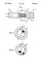
- FIG. 1illustrates by partial cross section a metal matrix bolt the composite core of fibers therein.
- FIG. 2is a cross section of the metal matrix bolt of FIG. 1.
- FIG. 3a composite core having multiple layers of spiral fibers.
- a metal matrix bolt 10is shown. As seen therein the metal matrix bolt 10 has a shell 11 comprised of a head 12, a shank 14 and a threaded section 16, without the threads shown thereon. Inside of the bolt 10 is a longitudinal space 18 which may run the full length of the bolt 10 or only partially, such as, for example, through the threaded section 16 and the shank 14. A metal cap 20 may be attached to the threaded section 16 to seal the space 18. The interior surface 22 surrounding the space 18 may be roughened.
- U.S. Pat. Nos. 2,949,059; 4,623,290; 4,717,302 and 4,824,314are incorporated by reference.
- U.S. Pat. No. 4,824,314discloses means for bonding a core material to an outer shell.
- the fibersare formed into at least one group of longitudinal fibers 24 and at least one group of spiral fibers 26 as seen in FIGS. 1 and 2.
- each group of spiral fiberscould have multiple layers therein.
- the preform consisting of the groups of fibersis placed within the space 18 and bonded together and to the interior surface 22.
- the spiral fiberswould be wrapped clockwise as seen from the head 12 around other fibers in a spiral fashion.
- the inclined angle of the spiral as seen from FIG. 1would be from about 30° to about 45° As a result, when the bolt 10 is torqued down, the spiral fibers would resist such.
- the combination of fiber group 24 and 26would allow the shank 14 to be of a smaller diameter because of the increased tensile strength. Further, the size of the bolt 10 could be reduced.
- Another benefit of the metal matrix bolt 10occurs as a result of the composite core 28 counter-balancing the expansion of the metal thus reducing axial growth and reducing pre-load values.
Landscapes
- Engineering & Computer Science (AREA)
- General Engineering & Computer Science (AREA)
- Mechanical Engineering (AREA)
- Manufacture Of Alloys Or Alloy Compounds (AREA)
Abstract
Description
The invention described herein may be manufactured and used by or for the Government for governmental purposes without the payment of any royalty thereon.
The present invention relates to fastener, and, in particular, relates to composite fasteners.
For fastening together portions of certain highly stressed constructions, such as aircraft or other assemblies requiring high strength and light weight, many variations of fasteners have been suggested. Most of these prior art fasteners have been made of a core material to which a different material has been applied as a thin protective coating, as by plating, galvanizing, and other application methods. In these fasteners, the reduction in weight has caused a corresponding reduction in strength and/or the ability to withstand one or more of the other forces caused by the stresses to which the assembly may be subjected.
Attempts to overcome the disadvantages of the prior art fasteners have been successful in part but have introduced other shortcomings. Typically, a molded, non-metallic fastener having an external coating of metal provides a lightweight fastener, but is unlikely to have the desired strength to withstand severe stress and tension forces without a significant increase in size. Also, metal coated non-metallic fasteners typically cannot be used in conjunction with metallic structures since the relatively thin metallic coating can be quickly destroyed by the metallic structures, permitting the assembled structures to act against the more fragile core material. Thus, under the high stress conditions in which these fasteners may be used, failures can occur by cutting through or shearing the core.
Another prior art fastener such as shown in U.S. Pat. No. 4,824,314, places a core material such as epoxy-graphite or alloys into a blank shell and the combination is formed into a bolt by the described technique. The shell would have a thickness such as would allow warm rolling and pressure forming. The core material is homogeneous.
Other prior art fasteners having a totally composite construction use selectively oriented resin-impregnated fibers to achieve strength. These fasteners lack sufficient strength both in tensile and shear loading to be of value in critical areas such as aircraft construction. Further, delamination of the fasteners has been a problem and as such special devices are used to reduce this damage. Examples of these are shown in U.S. Pat. Nos. 2,949,054; 4,623,290; and 4,717,302.
Thus, there is clearly a need for a fastener having a composite matrix construction within a metal shell.
The present invention comprises a metal matrix bolt having a metal shell with a core therein of selectively oriented fibers.
The metal shell has a head, a shank and a threaded section thereon. The shell has an interior space therein running longitudinally therethrough. The interior space may or may not be contained within the metal shell by caps thereon or by other means of sealing.
The core consists of a combination of selectively positioned fibers and, in particular, a first group of fibers running longitudinal and a second group of fibers spirally interfaced with the first group. Appropriate bonding of the core to the shell insures structural integrity.
Therefore, one object of the present invention is to provide a metal matrix bolt.
Another object of the present invention is to provide a metal matrix bolt having increased tensile strength.
Another object of the present invention is to provide a metal matrix bolt having reduced axial growth during thermal expansion.
These and many other objects and advantages of the present invention will be readily apparent to one skilled in the pertinent art from the following detailed description of a preferred embodiment of the invention and the related drawings.
FIG. 1 illustrates by partial cross section a metal matrix bolt the composite core of fibers therein.
FIG. 2 is a cross section of the metal matrix bolt of FIG. 1.
FIG. 3 a composite core having multiple layers of spiral fibers.
Referring to FIG. 1, ametal matrix bolt 10 is shown. As seen therein themetal matrix bolt 10 has ashell 11 comprised of ahead 12, ashank 14 and a threadedsection 16, without the threads shown thereon. Inside of thebolt 10 is alongitudinal space 18 which may run the full length of thebolt 10 or only partially, such as, for example, through the threadedsection 16 and theshank 14. Ametal cap 20 may be attached to the threadedsection 16 to seal thespace 18. Theinterior surface 22 surrounding thespace 18 may be roughened.
U.S. Pat. Nos. 2,949,059; 4,623,290; 4,717,302 and 4,824,314 are incorporated by reference. In particular, U.S. Pat. No. 4,824,314 discloses means for bonding a core material to an outer shell.
Inside thespace 18 is acomposite core 28 of fibers. The fibers are formed into at least one group oflongitudinal fibers 24 and at least one group ofspiral fibers 26 as seen in FIGS. 1 and 2.
All sizes and shapes shown in the Figures are only for illustration and have no bearing otherwise, unless so stated.
As seen in FIG. 3, there are 2 groups of spiral fibers interleaved between thelongitudinal fibers 24 for additional strength. Although only one layer of spiral fibers is shown, each group of spiral fibers could have multiple layers therein.
The preform consisting of the groups of fibers is placed within thespace 18 and bonded together and to theinterior surface 22.
The spiral fibers would be wrapped clockwise as seen from thehead 12 around other fibers in a spiral fashion. The inclined angle of the spiral as seen from FIG. 1 would be from about 30° to about 45° As a result, when thebolt 10 is torqued down, the spiral fibers would resist such. The combination offiber group shank 14 to be of a smaller diameter because of the increased tensile strength. Further, the size of thebolt 10 could be reduced. Another benefit of themetal matrix bolt 10 occurs as a result of thecomposite core 28 counter-balancing the expansion of the metal thus reducing axial growth and reducing pre-load values.
Clearly, many modifications and variations of the present invention are possible in light of the above teachings and it is therefore understood, that within the inventive scope of the inventive concept, the invention may be practiced otherwise than specifically claimed.
Claims (5)
1. An improved metal matrix bolt, said metal matrix bolt comprising:
a metal shell, said metal shell comprising:
a head;
a shank; said shank attached to said head; and
a threaded section, said threaded section attached to said shank, said shell having a longitudinal space substantially therethrough; and
a composite core, said composite core being bonded within said longitudinal space, said composite core comprising:
at least one group of longitudinal fibers; and
at least one group of spiral fibers, said spiral fibers being bonded to said at least one group of longitudinal fibers.
2. An improved metal matrix bolt as defined in claim 1 wherein there is only one group of said longitudinal and said spiral fibers.
3. An improved metal matrix bolt as defined in claim 1 wherein said spiral fibers are wrapped clockwise about said longitudinal fibers as viewed from said head.
4. An improved metal matrix bolt as defined in claim 3 wherein said spiral fibers are inclined at an angle of about 30° to about 45° to an axis of said bolt.
5. An improved metal matrix bolt as defined in claim 1 wherein said fibers are composite fibers.
Priority Applications (1)
| Application Number | Priority Date | Filing Date | Title |
|---|---|---|---|
| US07/957,976US5292215A (en) | 1992-10-07 | 1992-10-07 | Metal bolt with a composite core for enhancement |
Applications Claiming Priority (1)
| Application Number | Priority Date | Filing Date | Title |
|---|---|---|---|
| US07/957,976US5292215A (en) | 1992-10-07 | 1992-10-07 | Metal bolt with a composite core for enhancement |
Publications (1)
| Publication Number | Publication Date |
|---|---|
| US5292215Atrue US5292215A (en) | 1994-03-08 |
Family
ID=25500437
Family Applications (1)
| Application Number | Title | Priority Date | Filing Date |
|---|---|---|---|
| US07/957,976Expired - Fee RelatedUS5292215A (en) | 1992-10-07 | 1992-10-07 | Metal bolt with a composite core for enhancement |
Country Status (1)
| Country | Link |
|---|---|
| US (1) | US5292215A (en) |
Cited By (26)
| Publication number | Priority date | Publication date | Assignee | Title |
|---|---|---|---|---|
| US5567096A (en)* | 1994-09-13 | 1996-10-22 | Howard; Douglas D. | Shear-pin system for logging truck bunk |
| US6045310A (en)* | 1997-10-06 | 2000-04-04 | United Technologies Corporation | Composite fastener for use in high temperature environments |
| RU2170860C1 (en)* | 2000-05-16 | 2001-07-20 | Открытое акционерное общество "Автонормаль" | Bolt with shaped head |
| US20030202861A1 (en)* | 2002-04-29 | 2003-10-30 | Charles Nelson | Fastener having supplemental support and retention capabilities |
| US20060193713A1 (en)* | 2003-02-18 | 2006-08-31 | Anton Gerhard | Thread-cutting screw |
| US20070255315A1 (en)* | 2003-02-04 | 2007-11-01 | Damage Control Surgical Technologies, Inc. | Method and apparatus for solid organ tissue approximation |
| US20100047034A1 (en)* | 2008-08-21 | 2010-02-25 | Douglas Stephen | Hybrid composite-metal male fastener |
| US20100104395A1 (en)* | 2008-08-21 | 2010-04-29 | Robert Stephen | Hybrid composite-metal male fasteners |
| US20100215901A1 (en)* | 2009-02-26 | 2010-08-26 | Edward Claude Rice | Composite spacer |
| US20110111172A1 (en)* | 2009-11-06 | 2011-05-12 | The Boeing Company | Compression Molding Method and Reinforced Thermoplastic Parts Molded Thereby |
| US20110282395A1 (en)* | 2009-01-16 | 2011-11-17 | Carbofix Orthopedics Ltd. | Composite material bone implant |
| EP2497963A1 (en)* | 2011-03-10 | 2012-09-12 | Siemens Aktiengesellschaft | Screw or bolt comprising two different materials |
| US20130149139A1 (en)* | 2011-12-08 | 2013-06-13 | Thomas Tracy Wallace | Dynamic load reduction system |
| US8465241B2 (en)* | 2007-10-31 | 2013-06-18 | The Boeing Company | Composite fasteners containing multiple reinforcing fiber types |
| US20130315689A1 (en)* | 2009-06-03 | 2013-11-28 | Samsung Heavy Industries Co., Ltd. | Fiber reinforced plastic bolt and method for producing the same |
| US8613580B2 (en) | 2011-04-28 | 2013-12-24 | Lockheed Martin Corporation | Fastening device |
| US20140234052A1 (en)* | 2013-02-21 | 2014-08-21 | The Boeing Company | Hybrid Fastener and Method of Making the Same |
| US9101427B2 (en) | 2010-06-07 | 2015-08-11 | Carbofix Orthopedics Ltd. | Self tapping insert |
| US9283706B2 (en) | 2013-12-03 | 2016-03-15 | The Boeing Company | Method and apparatus for compression molding fiber reinforced thermoplastic parts |
| US9302434B2 (en) | 2013-12-03 | 2016-04-05 | The Boeing Company | Thermoplastic composite support structures with integral fittings and method |
| US9526549B2 (en) | 2012-01-16 | 2016-12-27 | Carbofix Orthopedics Ltd. | Bone screw with insert |
| US9623612B2 (en) | 2013-02-21 | 2017-04-18 | The Boeing Company | Method for fabricating composite fasteners |
| US10154867B2 (en) | 2010-06-07 | 2018-12-18 | Carbofix In Orthopedics Llc | Multi-layer composite material bone screw |
| US10617458B2 (en) | 2015-12-23 | 2020-04-14 | Carbofix In Orthopedics Llc | Multi-layer composite material bone screw |
| CN111271361A (en)* | 2020-03-23 | 2020-06-12 | 山西佰得拓普工贸有限公司 | Fastening screw for vulcanizing machine, preparation method of fastening screw and vulcanizing machine |
| US10808747B2 (en)* | 2017-12-22 | 2020-10-20 | Ford Global Technologies, Llc | Frictionally damped fasteners and methods of manufacturing the same |
Citations (11)
| Publication number | Priority date | Publication date | Assignee | Title |
|---|---|---|---|---|
| US2510693A (en)* | 1944-03-29 | 1950-06-06 | Lee B Green | Fastening member |
| US2949054A (en)* | 1954-07-19 | 1960-08-16 | Glastic Corp | Threaded shaft of glass fiber reinforced plastic |
| US4063838A (en)* | 1976-05-07 | 1977-12-20 | Fiber Glass Systems, Inc. | Rod construction and method of forming the same |
| US4620401A (en)* | 1985-04-26 | 1986-11-04 | Societe Nationale De L'amiante | Structural rod for reinforcing concrete material |
| US4623290A (en)* | 1983-02-28 | 1986-11-18 | Asahi Kasei Kogyo Kabushiki Kaisha | Externally threaded fiber-reinforced plastic member and a method of producing the same |
| US4717302A (en)* | 1984-06-18 | 1988-01-05 | Tiodize Company, Inc. | Composite fastener |
| US4718801A (en)* | 1986-07-24 | 1988-01-12 | Microdot Inc. | Composite core fastener |
| US4824314A (en)* | 1985-02-19 | 1989-04-25 | Northrop Corporation | Composite fastener system and manufacturing method thereof |
| US4863330A (en)* | 1987-07-15 | 1989-09-05 | Northrop Corporation | Composite fastener and method of manufacture |
| US5127783A (en)* | 1989-05-25 | 1992-07-07 | The B.F. Goodrich Company | Carbon/carbon composite fasteners |
| US5152650A (en)* | 1990-06-04 | 1992-10-06 | Kitagawa Industries Co., Ltd. | Electrically conductive synthetic resin bolt |
- 1992
- 1992-10-07USUS07/957,976patent/US5292215A/ennot_activeExpired - Fee Related
Patent Citations (11)
| Publication number | Priority date | Publication date | Assignee | Title |
|---|---|---|---|---|
| US2510693A (en)* | 1944-03-29 | 1950-06-06 | Lee B Green | Fastening member |
| US2949054A (en)* | 1954-07-19 | 1960-08-16 | Glastic Corp | Threaded shaft of glass fiber reinforced plastic |
| US4063838A (en)* | 1976-05-07 | 1977-12-20 | Fiber Glass Systems, Inc. | Rod construction and method of forming the same |
| US4623290A (en)* | 1983-02-28 | 1986-11-18 | Asahi Kasei Kogyo Kabushiki Kaisha | Externally threaded fiber-reinforced plastic member and a method of producing the same |
| US4717302A (en)* | 1984-06-18 | 1988-01-05 | Tiodize Company, Inc. | Composite fastener |
| US4824314A (en)* | 1985-02-19 | 1989-04-25 | Northrop Corporation | Composite fastener system and manufacturing method thereof |
| US4620401A (en)* | 1985-04-26 | 1986-11-04 | Societe Nationale De L'amiante | Structural rod for reinforcing concrete material |
| US4718801A (en)* | 1986-07-24 | 1988-01-12 | Microdot Inc. | Composite core fastener |
| US4863330A (en)* | 1987-07-15 | 1989-09-05 | Northrop Corporation | Composite fastener and method of manufacture |
| US5127783A (en)* | 1989-05-25 | 1992-07-07 | The B.F. Goodrich Company | Carbon/carbon composite fasteners |
| US5152650A (en)* | 1990-06-04 | 1992-10-06 | Kitagawa Industries Co., Ltd. | Electrically conductive synthetic resin bolt |
Cited By (53)
| Publication number | Priority date | Publication date | Assignee | Title |
|---|---|---|---|---|
| US5567096A (en)* | 1994-09-13 | 1996-10-22 | Howard; Douglas D. | Shear-pin system for logging truck bunk |
| US6045310A (en)* | 1997-10-06 | 2000-04-04 | United Technologies Corporation | Composite fastener for use in high temperature environments |
| RU2170860C1 (en)* | 2000-05-16 | 2001-07-20 | Открытое акционерное общество "Автонормаль" | Bolt with shaped head |
| US7182566B1 (en) | 2002-04-29 | 2007-02-27 | Charles Nelson | Fastener having supplemental support and retention capabilities |
| US6908275B2 (en) | 2002-04-29 | 2005-06-21 | Charles Nelson | Fastener having supplemental support and retention capabilities |
| US20030202861A1 (en)* | 2002-04-29 | 2003-10-30 | Charles Nelson | Fastener having supplemental support and retention capabilities |
| US8114124B2 (en)* | 2003-02-04 | 2012-02-14 | Damage Control Surgical Technologies, Inc. | Method and apparatus for solid organ tissue approximation |
| US20070255315A1 (en)* | 2003-02-04 | 2007-11-01 | Damage Control Surgical Technologies, Inc. | Method and apparatus for solid organ tissue approximation |
| US9155538B2 (en) | 2003-02-04 | 2015-10-13 | Damage Control Surgical Technologies, Inc. | Method and apparatus for solid organ tissue approximation |
| US8556933B2 (en) | 2003-02-04 | 2013-10-15 | Robert F. Buckman | Method and apparatus for solid organ tissue approximation |
| US20060193713A1 (en)* | 2003-02-18 | 2006-08-31 | Anton Gerhard | Thread-cutting screw |
| US7338243B2 (en)* | 2003-02-18 | 2008-03-04 | Toge-Dübel A. Gerhard KG | Thread-cutting screw |
| US8465241B2 (en)* | 2007-10-31 | 2013-06-18 | The Boeing Company | Composite fasteners containing multiple reinforcing fiber types |
| US8105004B2 (en)* | 2008-08-21 | 2012-01-31 | Robert Stephen | Hybrid composite-metal male fasteners |
| US20100104395A1 (en)* | 2008-08-21 | 2010-04-29 | Robert Stephen | Hybrid composite-metal male fasteners |
| US20100047034A1 (en)* | 2008-08-21 | 2010-02-25 | Douglas Stephen | Hybrid composite-metal male fastener |
| DE102009032990A1 (en) | 2008-08-21 | 2010-02-25 | NMC Group, Inc., Pomona | Male Hybrid Composite Metal Fastener |
| US7896599B2 (en)* | 2008-08-21 | 2011-03-01 | Douglas Stephen | Hybrid composite-metal male fastener |
| US20110282395A1 (en)* | 2009-01-16 | 2011-11-17 | Carbofix Orthopedics Ltd. | Composite material bone implant |
| US9101417B2 (en) | 2009-01-16 | 2015-08-11 | Carbofix Orthopedics Ltd. | Composite material bone implant |
| US8709055B2 (en)* | 2009-01-16 | 2014-04-29 | Carbofix Orthopedics Ltd. | Composite material bone implant |
| US10028777B2 (en) | 2009-01-16 | 2018-07-24 | Carbofix Orthopedics Ltd. | Composite material bone implant |
| US7897241B2 (en)* | 2009-02-26 | 2011-03-01 | Rolls-Royce Corporation | Composite spacer |
| US20100215901A1 (en)* | 2009-02-26 | 2010-08-26 | Edward Claude Rice | Composite spacer |
| US20130315689A1 (en)* | 2009-06-03 | 2013-11-28 | Samsung Heavy Industries Co., Ltd. | Fiber reinforced plastic bolt and method for producing the same |
| US9316244B2 (en)* | 2009-06-03 | 2016-04-19 | Sk Chemicals Co., Ltd. | Fiber reinforced plastic bolt and method for producing the same |
| US9205579B2 (en) | 2009-11-06 | 2015-12-08 | The Boeing Company | Compression molding method and reinforced thermoplastic parts molded thereby |
| US8709319B2 (en) | 2009-11-06 | 2014-04-29 | The Boeing Company | Compression molding method and reinforced thermoplastic parts molded thereby |
| US8709321B2 (en) | 2009-11-06 | 2014-04-29 | The Boeing Company | Compression molding method and reinforced thermoplastic parts molded thereby |
| US20110111172A1 (en)* | 2009-11-06 | 2011-05-12 | The Boeing Company | Compression Molding Method and Reinforced Thermoplastic Parts Molded Thereby |
| DE102010055732A1 (en) | 2009-12-22 | 2011-07-07 | NYLON MOLDING CORPORATION, Calif. | Male Hybrid Composite Metal Fasteners |
| US9974586B2 (en) | 2010-06-07 | 2018-05-22 | Carbofix Orthopedics Ltd. | Composite material bone implant |
| US10154867B2 (en) | 2010-06-07 | 2018-12-18 | Carbofix In Orthopedics Llc | Multi-layer composite material bone screw |
| US9370388B2 (en) | 2010-06-07 | 2016-06-21 | Carbofix Orthopedics Ltd. | Composite material bone implant |
| US9101427B2 (en) | 2010-06-07 | 2015-08-11 | Carbofix Orthopedics Ltd. | Self tapping insert |
| US10849668B2 (en) | 2010-06-07 | 2020-12-01 | Carbofix Orthopedics Ltd. | Composite material bone implant |
| CN103415712A (en)* | 2011-03-10 | 2013-11-27 | 西门子公司 | A screw or pin made of two different materials |
| EP2497963A1 (en)* | 2011-03-10 | 2012-09-12 | Siemens Aktiengesellschaft | Screw or bolt comprising two different materials |
| WO2012119827A1 (en)* | 2011-03-10 | 2012-09-13 | Siemens Aktiengesellschaft | Screw or pin made of two different materials |
| US8613580B2 (en) | 2011-04-28 | 2013-12-24 | Lockheed Martin Corporation | Fastening device |
| US9169728B2 (en)* | 2011-12-08 | 2015-10-27 | General Electric Company | Dynamic load reduction system |
| US20130149139A1 (en)* | 2011-12-08 | 2013-06-13 | Thomas Tracy Wallace | Dynamic load reduction system |
| US9526549B2 (en) | 2012-01-16 | 2016-12-27 | Carbofix Orthopedics Ltd. | Bone screw with insert |
| US20140234052A1 (en)* | 2013-02-21 | 2014-08-21 | The Boeing Company | Hybrid Fastener and Method of Making the Same |
| US9623612B2 (en) | 2013-02-21 | 2017-04-18 | The Boeing Company | Method for fabricating composite fasteners |
| US9238339B2 (en)* | 2013-02-21 | 2016-01-19 | The Boeing Company | Hybrid fastener and method of making the same |
| US10328643B2 (en) | 2013-02-21 | 2019-06-25 | The Boeing Company | Apparatus for fabricating composite fasteners |
| US10350718B2 (en) | 2013-02-21 | 2019-07-16 | The Boeing Company | Hybrid fastener and method of making the same |
| US9302434B2 (en) | 2013-12-03 | 2016-04-05 | The Boeing Company | Thermoplastic composite support structures with integral fittings and method |
| US9283706B2 (en) | 2013-12-03 | 2016-03-15 | The Boeing Company | Method and apparatus for compression molding fiber reinforced thermoplastic parts |
| US10617458B2 (en) | 2015-12-23 | 2020-04-14 | Carbofix In Orthopedics Llc | Multi-layer composite material bone screw |
| US10808747B2 (en)* | 2017-12-22 | 2020-10-20 | Ford Global Technologies, Llc | Frictionally damped fasteners and methods of manufacturing the same |
| CN111271361A (en)* | 2020-03-23 | 2020-06-12 | 山西佰得拓普工贸有限公司 | Fastening screw for vulcanizing machine, preparation method of fastening screw and vulcanizing machine |
Similar Documents
| Publication | Publication Date | Title |
|---|---|---|
| US5292215A (en) | Metal bolt with a composite core for enhancement | |
| US5785092A (en) | High-pressure fiber reinforced composite pipe joint | |
| US4216803A (en) | Self-sealing fuel lines | |
| US6918724B2 (en) | Fastening assembly and method for fastening a multi-layered laminate together | |
| US4406558A (en) | Gudgeon pin | |
| CA1059805A (en) | Container fastener system | |
| US5433570A (en) | Screw with unthreaded portion formed for absorbing bending loads | |
| US3207352A (en) | Laminated pressure vessels | |
| US5415079A (en) | Composite cylinder for use in aircraft hydraulic actuator | |
| EP3381665B1 (en) | Composite structural component with captive mechanical joint | |
| US4777869A (en) | Fluid actuator including a composite piston rod | |
| JP2018136021A (en) | Radiused lead-in section for interference fit fastener | |
| US6974555B2 (en) | Method of fabricating a damage tolerant shaft | |
| US5083888A (en) | Composite threaded collar | |
| US11466725B2 (en) | Composite shaft | |
| US4893657A (en) | Structure of the connecting end portion of composite tube having small diameter | |
| US20080283667A1 (en) | Hybrid composite-metal aircraft landing gear and engine support beams | |
| US12338855B2 (en) | Composite end connections | |
| US3313664A (en) | Method for making laminated pressure vessels | |
| EP2182198B1 (en) | Pressure container for high-temperature use and a method for production of same | |
| JPS5844518B2 (en) | rocket shell | |
| US4696233A (en) | High propellant mass fraction highly stress relieved end-burning grain structure | |
| US7730839B1 (en) | Interfacial stress reduction and load capacity enhancement system | |
| DE102019008390A1 (en) | Housing for a warhead and a method for producing a housing for a warhead | |
| CN115605343B (en) | Use of a fiber composite connecting section for connecting a tubular fiber composite structure to a connecting device |
Legal Events
| Date | Code | Title | Description |
|---|---|---|---|
| AS | Assignment | Owner name:UNITED STATES OF AMERICA, THE, AS REPRESENTED BY T Free format text:ASSIGNMENT OF ASSIGNORS INTEREST.;ASSIGNOR:UNITED TECHNOLOGIES CORPORATION;REEL/FRAME:006325/0900 Effective date:19921007 | |
| AS | Assignment | Owner name:UNITED TECHNOLOGIES, VIRGINIA Free format text:ASSIGNMENT OF ASSIGNORS INTEREST;ASSIGNOR:ROBERTS, HERBERT C., III;REEL/FRAME:006548/0068 Effective date:19920918 | |
| REMI | Maintenance fee reminder mailed | ||
| LAPS | Lapse for failure to pay maintenance fees | ||
| FP | Lapsed due to failure to pay maintenance fee | Effective date:19980311 | |
| STCH | Information on status: patent discontinuation | Free format text:PATENT EXPIRED DUE TO NONPAYMENT OF MAINTENANCE FEES UNDER 37 CFR 1.362 |