US5292097A - Work surface support - Google Patents
Work surface supportDownload PDFInfo
- Publication number
- US5292097A US5292097AUS07/907,483US90748392AUS5292097AUS 5292097 AUS5292097 AUS 5292097AUS 90748392 AUS90748392 AUS 90748392AUS 5292097 AUS5292097 AUS 5292097A
- Authority
- US
- United States
- Prior art keywords
- support means
- elements
- shaped profile
- link
- face
- Prior art date
- Legal status (The legal status is an assumption and is not a legal conclusion. Google has not performed a legal analysis and makes no representation as to the accuracy of the status listed.)
- Expired - Lifetime
Links
Images


Classifications
- A—HUMAN NECESSITIES
- A47—FURNITURE; DOMESTIC ARTICLES OR APPLIANCES; COFFEE MILLS; SPICE MILLS; SUCTION CLEANERS IN GENERAL
- A47B—TABLES; DESKS; OFFICE FURNITURE; CABINETS; DRAWERS; GENERAL DETAILS OF FURNITURE
- A47B21/00—Tables or desks for office equipment, e.g. typewriters, keyboards
- A47B21/03—Tables or desks for office equipment, e.g. typewriters, keyboards with substantially horizontally extensible or adjustable parts other than drawers, e.g. leaves
- A47B21/0314—Platforms for supporting office equipment
- A47B2021/0321—Keyboard supports
- A47B2021/0328—Keyboard supports of the pantograph type
- A—HUMAN NECESSITIES
- A47—FURNITURE; DOMESTIC ARTICLES OR APPLIANCES; COFFEE MILLS; SPICE MILLS; SUCTION CLEANERS IN GENERAL
- A47B—TABLES; DESKS; OFFICE FURNITURE; CABINETS; DRAWERS; GENERAL DETAILS OF FURNITURE
- A47B21/00—Tables or desks for office equipment, e.g. typewriters, keyboards
- A47B21/03—Tables or desks for office equipment, e.g. typewriters, keyboards with substantially horizontally extensible or adjustable parts other than drawers, e.g. leaves
- A47B21/0314—Platforms for supporting office equipment
- A47B2021/0321—Keyboard supports
- A47B2021/0335—Keyboard supports mounted under the worksurface
- Y—GENERAL TAGGING OF NEW TECHNOLOGICAL DEVELOPMENTS; GENERAL TAGGING OF CROSS-SECTIONAL TECHNOLOGIES SPANNING OVER SEVERAL SECTIONS OF THE IPC; TECHNICAL SUBJECTS COVERED BY FORMER USPC CROSS-REFERENCE ART COLLECTIONS [XRACs] AND DIGESTS
- Y10—TECHNICAL SUBJECTS COVERED BY FORMER USPC
- Y10S—TECHNICAL SUBJECTS COVERED BY FORMER USPC CROSS-REFERENCE ART COLLECTIONS [XRACs] AND DIGESTS
- Y10S248/00—Supports
- Y10S248/917—Video display screen support
- Y10S248/918—Ancillary device support associated with a video display screen
Definitions
- This inventionrelates to a work surface support, and is a continuation-in-part of Ser. No. 07/607,448, now abandoned, filed Oct. 31, 1990.
- a particular application of the inventionrelates to the support for a keyboard for a computer work station.
- the inventionresides in a support means for supporting a support platform from a fixed base whereby the support platform is movable between a first position at least partially below the fixed base and a second position in front of the fixed base, said support means comprising a first element adapted to be mounted to the support platform, a second element adapted to be affixed to said fixed base, a pair of linkage elements each pivotally fixed at one end to said first element at spaced intervals on said first element and each pivotally mounted at the other end to said second element at spaced locations on said second element to enable movement of the support platform between the first and second positions whereby throughout such movement the attitude of said support platform remains substantially constant, said support means further comprising a locking means for locking said support platform in a range of positions including said second position, said locking means comprising a first locking member supported on one of said linkage elements and having a first engagement face engagable with a second engagement face provided on a second locking member provided on another of said elements said locking members being relatively moveable between a released
- the pawl member and locking surfaceare gravitationally biassed into locking inter-engagement.
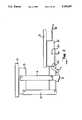
- FIG. 1is a side elevation of the first embodiment in the region of the second position
- FIG. 2is a side elevation of the first embodiment in the first position
- FIG. 3is a side elevation of the second embodiment in the region of the second position
- FIG. 4is a side elevation of the second embodiment in the first position
- FIG. 5is a side elevation of the third embodiment in the region of the second position
- FIG. 6is a side elevation of the third embodiment in the first position
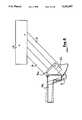
- FIG. 7is a side elevation of a fourth embodiment of the invention in its second position
- FIG. 8is a side elevation of the fourth embodiment at an intermediate position between its first and second position
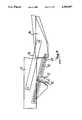
- FIG. 9is a side elevation of a fifth embodiment at or near its second position
- FIG. 10is a side elevation of the fifth embodiment intermediate of the first and second position
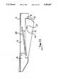
- FIG. 11is a side elevation of the sixth embodiment at its second position
- FIG. 12is a side elevation of the sixth embodiment at a position intermediate its first and second position
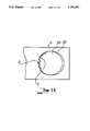
- FIG. 13is an enlarged view of an alternative arrangement between the pawl member and locking surface to be utilised with the sixth embodiment
- FIGS. 14, 15 and 16are side elevations of the seventh embodiment in its first position; an adjusting position and second position respectively;
- FIGS. 17, 18 and 19are side elevations of the eighth embodiment in various positions
- FIGS. 20 and 21are side elevations of the ninth embodiment with the elements in the locked and unlocked positions respectively.
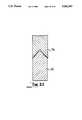
- FIG. 22is a part sectional view of the locking members of the ninth embodiment.
- the first embodiment shown at FIG. 1comprises a support for a support platform 11 to facilitate movement of the support platform 11 relative to a fixed member 12 whereby the support platform 11 is movable between a position in front of the fixed member 12 as shown at FIG. 1, and a position below the fixed member 12 as shown at FIG. 2.
- the supportcomprises a first member 13 which is adapted to be fixed underneath the fixed member 12 and a second member 14 which is adapted to be fixed under the support platform and which extends rearwardly from the rear edge of the support platform 11.
- the first and second members 13 and 14are interconnected by a pair of substantially parallel link elements 15 and 16 which are pivotally connected at their ends to the first member 13 and second member 14 respectively at spaced positions of the respective members.
- the result of the presence of the parallelogram linkage provided by link elements 15 and 16 and their pivotal interconnection with the first and second members at 13 and 14is such that support platform 11 is capable of movement from a position in front of the fixed member 12 to a position below the fixed member 12 as shown as FIGS. 1 and 2 whereby throughout such movement the attitude of the support platform 11 remains substantially constant.
- the second member 14pivotally supports a pawl member 17 which has a general configuration of a bellcrank where one arm extends forwardly and is provided with a forwardly directed handle 18 which is accessible from the front of the support platform 11.
- the other arm of the pawl member 17is provided with a set of serrations or teeth which are engagable with a serrated curved locking surface, which is provided at one end of one of the link elements 16 where the mounting of the one link element 16 to the first member is the centre of curvature of the curved locking surface.
- the support platform 11On inter-engagement of the respective serrated formations of the pawl member 17 and locking surface 19 the support platform 11 is retained in position.
- the pawl 17is engagable with the locking surface 19 for a range of positions including the second position at which the support platform 11 is located forward of the fixed member 12.
- the support platformcan be adjusted to a height satisfactory to the user.
- the effect of the counterweighting action provided by the handle 18causes the pawl member 17 to be biased under the influence of the gravity into engagement with the locking surface 19.
- the support platform 11is supported from a fixed member 12 in a similar manner to that of the first embodiment, the only difference between the embodiments relates to the locking means.
- the locking meansfurther controls the attitude of the support platform 11.
- the support platform 11is supported from the second member 14 through a transverse pivot axis 20 such that it is pivotable on the second member 14 about said transverse axis.
- the pivotal movement of the support platform 11is controlled through the pawl member 17 which is formed as a bellcrank member of similar form to that of the first embodiment and which is engagable with a first locking surface 19 provided at the end of the first link element 16.
- the engagement between the pawl member 17 and the first locking surfaceis similar to that of the first embodiment and the pawl member 17 is operated through a handle 18 in a similar manner to that of first embodiment.
- first and second embodimentsrelate to the difference between the first and second embodiments however, resides in the presence of a serrated formation at the other end of the other arm of the pawl member 17 which is engagable with a second locking surface 22 which has a serrated configuration and is provided on the support 21 of the support platform 11.
- a serrated formationat the other end of the other arm of the pawl member 17 which is engagable with a second locking surface 22 which has a serrated configuration and is provided on the support 21 of the support platform 11.
- the support platformOn disengagement of the pawl member 17 from engagement with the first locking surface 19 provided on the first link element 16 and also with the second locking surface 22 provided on the support 21 the support platform is not only capable of being raised or lowered with respect to the fixed member 12 but is also capable of pivotal movement about said transverse axis 19.
- the third embodiment shown at FIGS. 5 and 6again comprises a support platform 11 and a fixed member 12 of a similar form to that of the first and second embodiments.
- the locking meanshowever, comprises an arcuate element 23 which is fixed at one end to the first member 13 to be pivotal thereon and is associated with a handle 18 which extends forwardly from the locking member underneath the fixed member 12 to be accessible from the front of the fixed member 12.
- the arcuate member 23is formed along its curved surface with a serrated locking surface 19 and acts as a counterweight such that under the influence of gravity it will pivot forwardly (i.e. the handle will pivot upwardly) whereby the handle 18, unless otherwise restrained, will bear against the underneath of the fixed surface 16.
- the locking element 23is associated with a fixed pawl member 25 in the form of a stop or abutment divided on the first link element 16 whereby for a range of positions including the second position of the support platform 11 the pawl member 25 is engagable with one of the notches 24 provided on the locking surface of the arcuate member 23. Due to the gravitational biasing provided by the counterweighting effect of the arcuate member 22 the locking member 23 is maintained in engagement with the pawl member 25. To effect disengagement therebetween, the operating handle 18 is pushed downwardly to bring the arcuate member 25 out of engagement with the pawl member.
- the configuration of the teeth provided on the pawl member 17 and the locking surface 19 in each of the embodiments described abovemay be such that the support platform 11 can be raised from a locked position without the need to manipulate the locking member 18. When raised to a fresh position the support platform will be locked in that position. To the lower the support platform 11 it is necessary to raise the handle 18 to effect disengagement between the pawl member 17 and the locking surface 19.
- the fourth, fifth, sixth and seventh embodimentswhich are shown at FIGS. 7 to 16 incorporate a locking means which does not necessitate the utilisation of a handle to effect disengagement or engagement between the pawl member and the locking surface.
- the activation of the pawl memberis effected through pivotal movement of the support platform with respect to the link elements.
- the pawl memberis disengaged from a locking surface which then allows for the adjustment of the height of the platform while the support platform is in the raised position and on return of the platform under the influence of gravity to its at rest position the pawl member is re-engaged with the locking surface over a range of movements.
- the support platform 11is supported from the fixed member 12 through a pair of pivotal links 15 and 16 as is the case in each of the previous embodiments.
- the second memberhowever comprises a first portion 14a, which pivotally supports the ends of the link members and a second portion 14b is pivotally supported from the second member 14.
- the serrated locking surface 19is provided on the end of one of the link members 15 and the serrated pawl member 17 is supported from underneath the platform 11 and is engagable with the teeth of the locking surface 19.
- the second portion 14b of the second member which supports the platform 11will pivot on the first portion 14a of the second member to a position at which the teeth of the pawl member 17 and the locking surface 19 are inter-engaged.
- the platform 11is lifted at its outer edge to cause pivotal movement between the portions 14a and 14b of the second member and while in that position the platform 11 may be transposed vertically to the desired position.
- the pawl member 17is re-engaged with the locking surface 19 to retain the support platform in position. Any additional weight supported by the support platform 11 will only serve to enhance such engagement.
- the pivotal interconnection between the first member and the support platform 11is similar to that of the first embodiment with the exception that the one link member 15 is telescopic in nature and is provided with a biassing means which can take the form of a spring 27 accommodated within the one link element between the pivotal mountings of the one link element to the first and second members 13 and 14.
- the spring 27biasses the one link member to its minimum length.
- the locking surface 19is mounted to the first member 13 and it is provided intermediate of the length of the one link member 15.
- the pawl member 17is mounted to the one link member 15 such that it is biassed into engagement with the locking surface 19 as a result of the action of the spring 27.
- the support platform 11which is supported on the second member 14 is lifted at its outer edge to effect pivotal movement about the mounting of the second member to the other link member 16 which serves to extend the length of the one link member 15 and thus disengage the pawl member 17 from the locking surface 19.
- the outer edge of the support platform 11is then lowered to effect re-engagement between the pawl member 17 and the locking surface 19.
- the locking arrangementcomprises a serrated locking surface 19 which is provided on the end of the one link element 15 adjacent the first member 13 while the pawl member comprises a fixed stop 17 which is provided on the first member 13.
- the pivot for the one link element 15 on the first member 13comprises a pivot pin 30 which is receivable in an elongate slot 29.
- the axis of the elongate slot 29is substantially parallel to the main axis of the one link member 15 and as a result of the engagement between the pivot pin 30 and the elongate slot 29 the second member 14 is capable of some relative pivotal movement on the other link member 16 which is independent of pivotal movement of the second member on the one link member 15.
- the one link member 15is caused to move longitudinally on the pivot pin 30 by virtue of the elongate slot 29.
- a biassing spring 28is provided between the first and second members 13 and 14 to extend between the pivot for the one link member 15 on the second member 14 and the pivot of the other link member 16 on the first member 13.
- the one link member 15is biassed to a position at which the pivot pin engages the end of the elongate slot closest to the second member 14 and as a result the locking surface 19 is biassed into engagement with the pawl member 17.
- FIG. 13discloses an alternative pivotal locking arrangement to that shown with respect to the sixth embodiment shown in FIGS. 11 and 12.
- the pivot pinis of enlarged dimensions and is received in an elliptical aperture 29.
- the surfaces of the pivot pin 30 and elliptical slot 29 which are most adjacent to the second member 14are formed with a complementary locking surface 19 and pawl member 17 respectively.
- the pivot pinis capable of radial transposition within the elliptical slot 29 and as a result of such transposition the locking surface 19 on the pivot pin 30 is disengaged from the pawl member.
- the seventh embodiment as shown at FIGS. 14, 15 and 16provides a locking arrangement whereby the one and other link elements 15 and 16 are lockingly inter-engaged.
- the locking arrangementcomprises an elongate slot 33 formed in the one link element 15 where the central axis of the slot is oblique to the central axis of the one link element 15.
- a notched locking surface 19is provided along the length of one side of the slot.
- the slot 33receives a pin supported from the other link element 16 and which comprises the fixed pawl member 17 and which is translatable along the length of the slot 33 but which is engagable with each of the notches provided in the locking surface 19.
- the location of the fixed pawl member 17 along the notched locking surface 19determines the position of the second member 14 relative to the first member 13.
- the second member 14is supported from the link elements by means of a fixed pivot provided on the one link element 16 and a translatable pivot provided on the other link element 15.
- the translatable pivotcomprises a second elongate slot 31 formed in the end of the one link element 15.
- the central axis of whichis oblique to the central axis of the other link element 15 and in opposed orientation to that of the first slot 33 accommodating the locking surface 19.
- the translatable pivotfurther comprises a pivot pin 32 which is provided on the second member 14 and is translatable along the length of the second slot 31.
- the second member 14When the second member 14 is pivoted on the other link element 16 without corresponding pivotal movement on the one link element 15 there is a transposition of the one link element 15 with respect to the other link member 16 which causes disengagement of the fixed pawl member 17 provided on the other link member 16 from the locking surface 19 provided in the first slot 33. As a result the second member 14 is then capable of vertical translation with respect to the first member 13 whereby the pawl 17 can move for the length of the first slot 11.
- a suitable biassing meansis provided between the link members to bias the pawl member 17 into engagement with the locking surface 19.
- the biassing meanscan also serve to bias the platform towards an uppermost position whereby the biassing force may partially or completely overcome the influence of gravity.
- the eighth embodiment as shown at FIGS. 17, 18 and 19is generally of a similar form to that of the sixth embodiment shown at FIGS. 11 and 12.
- locking of the support platformis effected by an arcuate concave serrated surface 35 which is supported on the first member and a serrated formation 36 on the end of the one link member 15 most adjacent the serrated surface 35.
- spring biassingthere is no need for spring biassing to retain the locking surfaces in engagement since the weight of the second member 14 and the support platform will bias the surfaces into engagement.
- the ninth embodiment shown at FIGS. 20, 21 and 22is of very similar form to the eighth embodiment of FIGS. 19, 20 and 21.
- the exception provided by the ninth embodimenthowever relates to the nature of the locking inter-engagement between the locking surfaces.
- the locking inter-engagementis effected through complementary serrated formation provided on the opposed locking surfaces.
- the locking surfacesare frictionally inter-engaged.
- the arcuate locking surface 35has a convex V-shaped profile while the adjacent end 36 of the one link member is formed with a V shaped groove which is receivable over the arcuate locking surface.
- the degree of divergence of the convex surface of the arcuate locking surface 35is greater than that of the groove on the one link element 15.
- the teethmay be formed such that the platform can be raised without positive disengagement of the teeth resulting from movement of the outer edge of the platform upwardly but such that positive disengagement is required to move the platform downwardly.
- the locking engagement between the locking surfacesmay be associated with any of the elements to effect the desired locking action.
- the locking interengagement between the locking membermay take any form appropriate to the circumstances and need not be restricted to the two particular forms of locking inter engagement described in relation to the above embodiments.
Landscapes
- Fittings On The Vehicle Exterior For Carrying Loads, And Devices For Holding Or Mounting Articles (AREA)
Abstract
Description
Claims (52)
Priority Applications (1)
| Application Number | Priority Date | Filing Date | Title |
|---|---|---|---|
| US07/907,483US5292097A (en) | 1989-10-31 | 1992-07-01 | Work surface support |
Applications Claiming Priority (4)
| Application Number | Priority Date | Filing Date | Title |
|---|---|---|---|
| AUPJ7143 | 1989-10-31 | ||
| AUPJ714389 | 1989-10-31 | ||
| US60744890A | 1990-10-31 | 1990-10-31 | |
| US07/907,483US5292097A (en) | 1989-10-31 | 1992-07-01 | Work surface support |
Related Parent Applications (1)
| Application Number | Title | Priority Date | Filing Date |
|---|---|---|---|
| US60744890AContinuation-In-Part | 1989-10-31 | 1990-10-31 |
Publications (1)
| Publication Number | Publication Date |
|---|---|
| US5292097Atrue US5292097A (en) | 1994-03-08 |
Family
ID=27157529
Family Applications (1)
| Application Number | Title | Priority Date | Filing Date |
|---|---|---|---|
| US07/907,483Expired - LifetimeUS5292097A (en) | 1989-10-31 | 1992-07-01 | Work surface support |
Country Status (1)
| Country | Link |
|---|---|
| US (1) | US5292097A (en) |
Cited By (54)
| Publication number | Priority date | Publication date | Assignee | Title |
|---|---|---|---|---|
| US5442859A (en)* | 1993-03-02 | 1995-08-22 | Naumann; Willi | Device for displaying CAD-drawings |
| US5626323A (en)* | 1995-05-31 | 1997-05-06 | Nova Solutions, Inc. | Adjustable keyboard holder |
| US5823487A (en)* | 1996-01-17 | 1998-10-20 | Minnesota Mining And Manufacturing Company | Keyboard support assembly |
| US5845587A (en)* | 1997-08-25 | 1998-12-08 | Signore, Incorporated | Two-part table top |
| US5924664A (en)* | 1997-03-12 | 1999-07-20 | Ergo View Technologies Corp. | Keyboard support mechanism |
| US6019332A (en)* | 1996-06-07 | 2000-02-01 | Ergotron, Inc. | Pivot/ratchet assembly and support system |
| WO2000027253A1 (en)* | 1998-11-10 | 2000-05-18 | Weber Knapp Company | Keyboard support mechanism |
| US6076785A (en)* | 1996-02-29 | 2000-06-20 | Innovative Office Products, Inc. | Ergonomic sit/stand keyboard support mechanism |
| US6079689A (en)* | 1993-09-28 | 2000-06-27 | Beitzel; Karl H | Mechanical arm mechanism for movably supporting multi-position multiple user surface members |
| US6092774A (en)* | 1998-11-23 | 2000-07-25 | Acco Brands, Inc. | Keyboard positioning system |
| US6116557A (en)* | 1998-07-10 | 2000-09-12 | Acco Brands, Inc. | Keyboard support system |
| US6135404A (en)* | 1998-11-05 | 2000-10-24 | Weber Knapp Company | Keyboard mounting mechanism |
| USD437857S1 (en) | 1999-04-20 | 2001-02-20 | Accuride International, Inc. | Pull-out keyboard tray |
| EP0933045A3 (en)* | 1998-01-30 | 2001-04-25 | Waterloo Furniture Components Limited | Keyboard support assembly |
| US6244547B1 (en) | 2000-02-01 | 2001-06-12 | Haworth, Inc. | Keyboard tray with adjustable wrist support |
| US6273382B1 (en) | 1999-09-30 | 2001-08-14 | Gregory L. Pemberton | Adjustable tilt-down keyboard support device |
| US6279859B2 (en)* | 1998-10-16 | 2001-08-28 | Haworth, Inc. | Keyboard pad with reversible mouse pad |
| WO2001021038A3 (en)* | 1999-09-24 | 2001-10-18 | Omid Rahmanian | Stress-free universal workstation module |
| US6450467B2 (en) | 1998-10-14 | 2002-09-17 | Work-Rite Ergonomic Accessories, Inc. | Tilt adjustable keyboard support |
| US6454369B1 (en) | 1999-05-04 | 2002-09-24 | Accuride International, Inc. | Pull-out keyboard tray |
| US6543949B1 (en) | 2000-03-23 | 2003-04-08 | Eugene B. Ritchey | Keyboard support apparatus |
| US6637072B2 (en) | 2000-09-29 | 2003-10-28 | Formway Furniture Limited | Castored base for an office chair |
| US20030214171A1 (en)* | 2002-05-14 | 2003-11-20 | Formway Furniture Limited | Height adjustable arm assembly |
| US20040035998A1 (en)* | 2001-10-02 | 2004-02-26 | Mccoy Richard W | Support arm |
| US6709058B1 (en) | 1999-04-09 | 2004-03-23 | Humanscale Corp. | Ergonomic chair |
| US20040195482A1 (en)* | 2002-10-30 | 2004-10-07 | Kollar Kevin J. | Adjustable support for data entry/interface device for computers or the like |
| US6802566B2 (en) | 2000-09-28 | 2004-10-12 | Formway Furniture Limited | Arm assembly for a chair |
| US20040245419A1 (en)* | 2003-01-17 | 2004-12-09 | Sweere Harry C. | Support arm |
| US20050092216A1 (en)* | 2003-10-31 | 2005-05-05 | Lima Jose M. | Adjustable work surface support |
| USD508918S1 (en) | 2004-04-06 | 2005-08-30 | Eugene B. Ritchey | Keyboard support |
| US20050206282A1 (en)* | 2004-03-17 | 2005-09-22 | Rev-A-Shelf Company Llc. | Shelf lift system |
| US20050218272A1 (en)* | 2004-04-06 | 2005-10-06 | Ritchey Eugene B | Keyboard support device and method |
| US20050264087A1 (en)* | 2004-05-13 | 2005-12-01 | Humanscale Corporation | Mesh chair component |
| US7013813B2 (en) | 2002-02-27 | 2006-03-21 | Baral Holdings Corp. | Adjustable work surface support mechanism |
| US7086634B1 (en) | 2000-09-20 | 2006-08-08 | 3M Innovative Properties Company | Adjustable keyboard tray |
| US20060273228A1 (en)* | 2005-06-06 | 2006-12-07 | Knape & Vogt Manufacturing Company | Adjustable support assembly |
| US20070001497A1 (en)* | 2005-06-20 | 2007-01-04 | Humanscale Corporation | Seating apparatus with reclining movement |
| US20070152122A1 (en)* | 2005-12-30 | 2007-07-05 | 3M Innovative Properties Company | Keyboard support assembly |
| US20070170326A1 (en)* | 2006-01-20 | 2007-07-26 | Workrite Ergonomics, Inc. | Height and tilt adjustable keyboard support |
| US20070257173A1 (en)* | 2003-11-24 | 2007-11-08 | Ergo View Technologies Corp. | Adjustable Support Mechanism |
| US20090013573A1 (en)* | 2007-07-10 | 2009-01-15 | Krinke Thomas A | Display holder |
| US20090257818A1 (en)* | 2008-04-09 | 2009-10-15 | Nec Access Technica, Ltd. | Angle adjustment device and image reading system using the same |
| US20100308188A1 (en)* | 2009-06-08 | 2010-12-09 | Baral Holdings Corp. | Undermount for height adjustable work surface mechanism |
| US20120037051A1 (en)* | 2010-08-16 | 2012-02-16 | Pi-Liang Wang | Computer Table That Is Folded and Expanded Easily And Quickly |
| US20120055380A1 (en)* | 2010-09-07 | 2012-03-08 | Chen-Yu Chung | Computer Table That Is Folded and Expanded Easily and Quickly |
| USD673401S1 (en) | 2005-05-13 | 2013-01-01 | Humanscale Corporation | Chair support structure |
| US20130312644A1 (en)* | 2012-05-25 | 2013-11-28 | Heman Miller, Inc. | Keyboard tray and attached mouse platform having multiple degrees of movement |
| US20150001909A1 (en)* | 2013-06-26 | 2015-01-01 | Grammer Ag | Vehicle seat and commercial vehicle with at least one vehicle seat |
| US9504326B1 (en) | 2012-04-10 | 2016-11-29 | Humanscale Corporation | Reclining chair |
| US9604557B2 (en) | 2014-04-16 | 2017-03-28 | Grammer Ag | Dust-insensitive slide rail |
| US9801471B2 (en) | 2014-04-17 | 2017-10-31 | Hni Technologies Inc. | Chair and chair control assemblies, systems, and methods |
| CN107319816A (en)* | 2017-07-26 | 2017-11-07 | 广州视源电子科技股份有限公司 | Foldable armrest and seat |
| CN115337153A (en)* | 2022-06-23 | 2022-11-15 | 蜂鸟代步(北京)科技有限公司 | Armrest mechanism and scooter |
| US20240407544A1 (en)* | 2023-06-06 | 2024-12-12 | CKnapp Sales, Inc. | Keyboard tray with swinging height adjustment |
Citations (7)
| Publication number | Priority date | Publication date | Assignee | Title |
|---|---|---|---|---|
| DE430585C (en)* | 1925-04-03 | 1926-06-19 | Adam Schneider Akt Ges Fa | Device for vertical adjustment and automatic locking of wall arm tables |
| DE880794C (en)* | 1950-10-08 | 1953-06-25 | Gerhard Dipl-Ing Brockhaus | Holding device for books or the like for reading in a lying position |
| US4616798A (en)* | 1982-06-07 | 1986-10-14 | Haworth, Inc. | Adjustable support for CRT keyboard |
| US4691888A (en)* | 1984-08-06 | 1987-09-08 | Cotterill Michael J | Keyboard support |
| US4706919A (en)* | 1986-12-17 | 1987-11-17 | Haworth, Inc. | Keyboard support with automatic lowering mechanism |
| US5031867A (en)* | 1986-09-04 | 1991-07-16 | Cotterill Michael J | Keyboard support apparatus |
| US5037054A (en)* | 1990-06-13 | 1991-08-06 | Waterloo Furniture Components Ltd. | Adjustable support mechanism for a keyboard platform |
- 1992
- 1992-07-01USUS07/907,483patent/US5292097A/ennot_activeExpired - Lifetime
Patent Citations (7)
| Publication number | Priority date | Publication date | Assignee | Title |
|---|---|---|---|---|
| DE430585C (en)* | 1925-04-03 | 1926-06-19 | Adam Schneider Akt Ges Fa | Device for vertical adjustment and automatic locking of wall arm tables |
| DE880794C (en)* | 1950-10-08 | 1953-06-25 | Gerhard Dipl-Ing Brockhaus | Holding device for books or the like for reading in a lying position |
| US4616798A (en)* | 1982-06-07 | 1986-10-14 | Haworth, Inc. | Adjustable support for CRT keyboard |
| US4691888A (en)* | 1984-08-06 | 1987-09-08 | Cotterill Michael J | Keyboard support |
| US5031867A (en)* | 1986-09-04 | 1991-07-16 | Cotterill Michael J | Keyboard support apparatus |
| US4706919A (en)* | 1986-12-17 | 1987-11-17 | Haworth, Inc. | Keyboard support with automatic lowering mechanism |
| US5037054A (en)* | 1990-06-13 | 1991-08-06 | Waterloo Furniture Components Ltd. | Adjustable support mechanism for a keyboard platform |
Cited By (100)
| Publication number | Priority date | Publication date | Assignee | Title |
|---|---|---|---|---|
| US5442859A (en)* | 1993-03-02 | 1995-08-22 | Naumann; Willi | Device for displaying CAD-drawings |
| US6079689A (en)* | 1993-09-28 | 2000-06-27 | Beitzel; Karl H | Mechanical arm mechanism for movably supporting multi-position multiple user surface members |
| US5626323A (en)* | 1995-05-31 | 1997-05-06 | Nova Solutions, Inc. | Adjustable keyboard holder |
| US5823487A (en)* | 1996-01-17 | 1998-10-20 | Minnesota Mining And Manufacturing Company | Keyboard support assembly |
| US6076785A (en)* | 1996-02-29 | 2000-06-20 | Innovative Office Products, Inc. | Ergonomic sit/stand keyboard support mechanism |
| US6019332A (en)* | 1996-06-07 | 2000-02-01 | Ergotron, Inc. | Pivot/ratchet assembly and support system |
| US7198239B2 (en)* | 1997-03-12 | 2007-04-03 | Ergo View Technologies Corp. | Keyboard support mechanism |
| US20060157628A1 (en)* | 1997-03-12 | 2006-07-20 | George Mileos | Keyboard support mechanism |
| US5924664A (en)* | 1997-03-12 | 1999-07-20 | Ergo View Technologies Corp. | Keyboard support mechanism |
| US6883764B1 (en) | 1997-03-12 | 2005-04-26 | Humanscale Corp. | Keyboard support mechanism |
| US20090090832A1 (en)* | 1997-03-12 | 2009-04-09 | Humanscale Corporation | Keyboard Support Mechanism |
| US20040099779A1 (en)* | 1997-03-12 | 2004-05-27 | George Mileos | Keyboard support mechanism |
| US7841569B2 (en) | 1997-03-12 | 2010-11-30 | Humanscale Corporation | Keyboard support mechanism |
| US7841570B2 (en) | 1997-03-12 | 2010-11-30 | Humanscale Corporation | Keyboard support mechanism |
| US5845587A (en)* | 1997-08-25 | 1998-12-08 | Signore, Incorporated | Two-part table top |
| US6322031B1 (en) | 1998-01-30 | 2001-11-27 | Waterloo Furniture Components, Ltd. | Keyboard support tray with releasable wedge lock |
| US6523797B2 (en)* | 1998-01-30 | 2003-02-25 | Waterloo Furniture Components, Ltd. | Keyboard support tray with releasable wedge lock |
| EP0933045A3 (en)* | 1998-01-30 | 2001-04-25 | Waterloo Furniture Components Limited | Keyboard support assembly |
| US6601812B2 (en)* | 1998-01-30 | 2003-08-05 | Waterloo Furniture Components, Ltd. | Keyboard support tray with releasable wedge lock |
| US6116557A (en)* | 1998-07-10 | 2000-09-12 | Acco Brands, Inc. | Keyboard support system |
| US6450467B2 (en) | 1998-10-14 | 2002-09-17 | Work-Rite Ergonomic Accessories, Inc. | Tilt adjustable keyboard support |
| US6565055B1 (en) | 1998-10-14 | 2003-05-20 | Work-Rite Ergonomic Accessories, Inc. | Tilt adjustable keyboard support |
| US6279859B2 (en)* | 1998-10-16 | 2001-08-28 | Haworth, Inc. | Keyboard pad with reversible mouse pad |
| US6135404A (en)* | 1998-11-05 | 2000-10-24 | Weber Knapp Company | Keyboard mounting mechanism |
| US6176456B1 (en) | 1998-11-10 | 2001-01-23 | Weber Knapp Company | Keyboard support mechanism |
| WO2000027253A1 (en)* | 1998-11-10 | 2000-05-18 | Weber Knapp Company | Keyboard support mechanism |
| AU754061B2 (en)* | 1998-11-10 | 2002-10-31 | Weber Knapp Company | Keyboard support mechanism |
| EP1156730A4 (en)* | 1998-11-10 | 2002-01-23 | Weber Knapp Co | Keyboard support mechanism |
| US6092774A (en)* | 1998-11-23 | 2000-07-25 | Acco Brands, Inc. | Keyboard positioning system |
| US6959965B2 (en) | 1999-04-09 | 2005-11-01 | Humanscale Corporation | Ergonomic chair |
| US20090091174A1 (en)* | 1999-04-09 | 2009-04-09 | Humanscale Corporation | Ergonomic Armrest |
| US7980631B2 (en) | 1999-04-09 | 2011-07-19 | Humanscale Corporation | Ergonomic armrest |
| US6709058B1 (en) | 1999-04-09 | 2004-03-23 | Humanscale Corp. | Ergonomic chair |
| USD437857S1 (en) | 1999-04-20 | 2001-02-20 | Accuride International, Inc. | Pull-out keyboard tray |
| USD447145S1 (en) | 1999-04-20 | 2001-08-28 | Accuride International Inc. | Pull-out keyboard tray |
| US6454369B1 (en) | 1999-05-04 | 2002-09-24 | Accuride International, Inc. | Pull-out keyboard tray |
| WO2001021038A3 (en)* | 1999-09-24 | 2001-10-18 | Omid Rahmanian | Stress-free universal workstation module |
| US6273382B1 (en) | 1999-09-30 | 2001-08-14 | Gregory L. Pemberton | Adjustable tilt-down keyboard support device |
| US6244547B1 (en) | 2000-02-01 | 2001-06-12 | Haworth, Inc. | Keyboard tray with adjustable wrist support |
| US6543949B1 (en) | 2000-03-23 | 2003-04-08 | Eugene B. Ritchey | Keyboard support apparatus |
| US7086634B1 (en) | 2000-09-20 | 2006-08-08 | 3M Innovative Properties Company | Adjustable keyboard tray |
| US7798573B2 (en) | 2000-09-28 | 2010-09-21 | Formway Furniture Limited | Reclinable chair |
| US6802566B2 (en) | 2000-09-28 | 2004-10-12 | Formway Furniture Limited | Arm assembly for a chair |
| US6908159B2 (en) | 2000-09-28 | 2005-06-21 | Formway Furniture Limited | Seat for a reclining office chair |
| US6910741B2 (en) | 2000-09-28 | 2005-06-28 | Formway Furniture Limited | Lumbar support |
| US6874852B2 (en) | 2000-09-28 | 2005-04-05 | Formway Furniture Limited | Lumbar support |
| US7441839B2 (en) | 2000-09-28 | 2008-10-28 | Formway Furniture Limited | Reclinable chair |
| US6817667B2 (en) | 2000-09-28 | 2004-11-16 | Formway Furniture Limited | Reclinable chair |
| US20050035638A1 (en)* | 2000-09-28 | 2005-02-17 | Formway Furniture Limited | Reclinable chair |
| US6637072B2 (en) | 2000-09-29 | 2003-10-28 | Formway Furniture Limited | Castored base for an office chair |
| US20040035998A1 (en)* | 2001-10-02 | 2004-02-26 | Mccoy Richard W | Support arm |
| US7013813B2 (en) | 2002-02-27 | 2006-03-21 | Baral Holdings Corp. | Adjustable work surface support mechanism |
| US20030214171A1 (en)* | 2002-05-14 | 2003-11-20 | Formway Furniture Limited | Height adjustable arm assembly |
| US6840582B2 (en) | 2002-05-14 | 2005-01-11 | Formway Furniture Limited | Height adjustable arm assembly |
| US6971624B2 (en) | 2002-10-30 | 2005-12-06 | Knape & Vogt Manufacturing Co. | Adjustable support for data entry/interface device |
| US20040195482A1 (en)* | 2002-10-30 | 2004-10-07 | Kollar Kevin J. | Adjustable support for data entry/interface device for computers or the like |
| US7252277B2 (en)* | 2003-01-17 | 2007-08-07 | Ergotron, Inc. | Support arm |
| US20040245419A1 (en)* | 2003-01-17 | 2004-12-09 | Sweere Harry C. | Support arm |
| US20050092216A1 (en)* | 2003-10-31 | 2005-05-05 | Lima Jose M. | Adjustable work surface support |
| US7707946B2 (en) | 2003-10-31 | 2010-05-04 | Baral Holdings Corp. | Adjustable work surface support |
| US20070257173A1 (en)* | 2003-11-24 | 2007-11-08 | Ergo View Technologies Corp. | Adjustable Support Mechanism |
| US7717383B2 (en) | 2003-11-24 | 2010-05-18 | Humanscale Corp | Adjustable support mechanism |
| US20050206282A1 (en)* | 2004-03-17 | 2005-09-22 | Rev-A-Shelf Company Llc. | Shelf lift system |
| US7108234B2 (en) | 2004-04-06 | 2006-09-19 | Ritchey Eugene B | Keyboard support device and method |
| USD508918S1 (en) | 2004-04-06 | 2005-08-30 | Eugene B. Ritchey | Keyboard support |
| US20050218272A1 (en)* | 2004-04-06 | 2005-10-06 | Ritchey Eugene B | Keyboard support device and method |
| US8240771B2 (en) | 2004-05-13 | 2012-08-14 | Humanscale Corporation | Mesh chair component |
| US20050264087A1 (en)* | 2004-05-13 | 2005-12-01 | Humanscale Corporation | Mesh chair component |
| USD673401S1 (en) | 2005-05-13 | 2013-01-01 | Humanscale Corporation | Chair support structure |
| US20060273228A1 (en)* | 2005-06-06 | 2006-12-07 | Knape & Vogt Manufacturing Company | Adjustable support assembly |
| US7188813B2 (en) | 2005-06-06 | 2007-03-13 | Knape & Vogt Manufacturing Company | Adjustable support assembly |
| US20070001497A1 (en)* | 2005-06-20 | 2007-01-04 | Humanscale Corporation | Seating apparatus with reclining movement |
| US8061775B2 (en) | 2005-06-20 | 2011-11-22 | Humanscale Corporation | Seating apparatus with reclining movement |
| US8777312B2 (en) | 2005-06-20 | 2014-07-15 | Humanscale Corporation | Seating apparatus with reclining movement |
| US20090152930A1 (en)* | 2005-06-20 | 2009-06-18 | Humanscale Corporation | Seating Apparatus With Reclining Movement |
| US20070152122A1 (en)* | 2005-12-30 | 2007-07-05 | 3M Innovative Properties Company | Keyboard support assembly |
| US7523905B2 (en) | 2006-01-20 | 2009-04-28 | Workrite Ergonomics, Inc. | Height and tilt adjustable keyboard support |
| US8272608B2 (en) | 2006-01-20 | 2012-09-25 | Workrite Ergonomics, Inc. | Height and tilt adjustable keyboard support |
| US20090206221A1 (en)* | 2006-01-20 | 2009-08-20 | Workrite Ergonomics, Inc. | Height and tilt adjustable keyboard support |
| US7942374B2 (en) | 2006-01-20 | 2011-05-17 | Workrite Ergonomics, Inc. | Height and tilt adjustable keyboard support |
| US20070170326A1 (en)* | 2006-01-20 | 2007-07-26 | Workrite Ergonomics, Inc. | Height and tilt adjustable keyboard support |
| US20110198468A1 (en)* | 2006-01-20 | 2011-08-18 | Workrite Ergonomics, Inc. | Height and tilt adjustable keyboard support |
| US7591096B2 (en) | 2007-07-10 | 2009-09-22 | Krinke Thomas A | Display holder |
| US20090300957A1 (en)* | 2007-07-10 | 2009-12-10 | Krinke Thomas A | Display holder |
| US20090013573A1 (en)* | 2007-07-10 | 2009-01-15 | Krinke Thomas A | Display holder |
| US20090257818A1 (en)* | 2008-04-09 | 2009-10-15 | Nec Access Technica, Ltd. | Angle adjustment device and image reading system using the same |
| US8727292B2 (en) | 2008-04-09 | 2014-05-20 | Nec Access Technica, Ltd. | Image reading system using an angle adjustment device |
| US20100308188A1 (en)* | 2009-06-08 | 2010-12-09 | Baral Holdings Corp. | Undermount for height adjustable work surface mechanism |
| US20120037051A1 (en)* | 2010-08-16 | 2012-02-16 | Pi-Liang Wang | Computer Table That Is Folded and Expanded Easily And Quickly |
| US20120055380A1 (en)* | 2010-09-07 | 2012-03-08 | Chen-Yu Chung | Computer Table That Is Folded and Expanded Easily and Quickly |
| US9504326B1 (en) | 2012-04-10 | 2016-11-29 | Humanscale Corporation | Reclining chair |
| US20130312644A1 (en)* | 2012-05-25 | 2013-11-28 | Heman Miller, Inc. | Keyboard tray and attached mouse platform having multiple degrees of movement |
| US20150001909A1 (en)* | 2013-06-26 | 2015-01-01 | Grammer Ag | Vehicle seat and commercial vehicle with at least one vehicle seat |
| US9315128B2 (en)* | 2013-06-26 | 2016-04-19 | Grammer Ag | Vehicle seat and commercial vehicle with at least one vehicle seat |
| US9604557B2 (en) | 2014-04-16 | 2017-03-28 | Grammer Ag | Dust-insensitive slide rail |
| US9801471B2 (en) | 2014-04-17 | 2017-10-31 | Hni Technologies Inc. | Chair and chair control assemblies, systems, and methods |
| US10455940B2 (en) | 2014-04-17 | 2019-10-29 | Hni Technologies Inc. | Chair and chair control assemblies, systems, and methods |
| CN107319816A (en)* | 2017-07-26 | 2017-11-07 | 广州视源电子科技股份有限公司 | Foldable armrest and seat |
| CN115337153A (en)* | 2022-06-23 | 2022-11-15 | 蜂鸟代步(北京)科技有限公司 | Armrest mechanism and scooter |
| US20240407544A1 (en)* | 2023-06-06 | 2024-12-12 | CKnapp Sales, Inc. | Keyboard tray with swinging height adjustment |
Similar Documents
| Publication | Publication Date | Title |
|---|---|---|
| US5292097A (en) | Work surface support | |
| US6176456B1 (en) | Keyboard support mechanism | |
| US10842257B2 (en) | Height adjustable desk for placing on an existing desktop | |
| US3436046A (en) | Infinite positioning mechanism for a movable arm | |
| US6135404A (en) | Keyboard mounting mechanism | |
| US4194452A (en) | Convertible table | |
| US7475944B2 (en) | Reclining and convertible seating furniture with trendelenburg feature | |
| US8276525B2 (en) | Height-adjustable equipment stand | |
| US6270047B1 (en) | Keyboard tilt mechanism | |
| CA2270446A1 (en) | Dual function inboard barrier/bridgeplate assembly for wheelchair lifts | |
| EP0723889B1 (en) | Vehicle seat slide | |
| US6523797B2 (en) | Keyboard support tray with releasable wedge lock | |
| US5039054A (en) | Safe height-adjusting device | |
| US5292118A (en) | Basketball backboard elevator system | |
| US4429919A (en) | Composite inertia latch for vehicle seat back | |
| GB2142899A (en) | Counterbalancing mechanism for the ramp of a dockboard | |
| US6905102B2 (en) | Keyboard support bracket structure | |
| US3966159A (en) | Safety latch for trays | |
| US5195205A (en) | Dock leveler operating apparatus | |
| KR0172597B1 (en) | Height adjuster | |
| WO1993025115A1 (en) | Support means | |
| JPH0642515Y2 (en) | Headrest adjustment device | |
| SE454401B (en) | DEVICE FOR HEADING, LOWERING AND / OR TREATING FORMS LIKE TABLETS, CHARGERS AND SIMILAR | |
| US4467891A (en) | Lock mechanism for extension ladder | |
| JPH09295797A (en) | Elevator for object |
Legal Events
| Date | Code | Title | Description |
|---|---|---|---|
| AS | Assignment | Owner name:TRENTON PTY LTD, AUSTRALIA Free format text:ASSIGNMENT OF ASSIGNORS INTEREST;ASSIGNOR:RUSSELL, EDWIN ROBIN;REEL/FRAME:006800/0698 Effective date:19931206 | |
| STCF | Information on status: patent grant | Free format text:PATENTED CASE | |
| FPAY | Fee payment | Year of fee payment:4 | |
| AS | Assignment | Owner name:SOFTVIEW COMPUTER PRODUCTS CORP., NEW YORK Free format text:ASSIGNMENT OF ASSIGNORS INTEREST;ASSIGNORS:RUSSELL, EDWIN R.;TRENTON PTY LTD.;REEL/FRAME:009214/0398 Effective date:19980523 | |
| FPAY | Fee payment | Year of fee payment:8 | |
| SULP | Surcharge for late payment | Year of fee payment:7 | |
| RR | Request for reexamination filed | Effective date:20041013 | |
| REMI | Maintenance fee reminder mailed | ||
| FPAY | Fee payment | Year of fee payment:12 | |
| SULP | Surcharge for late payment | Year of fee payment:11 | |
| B1 | Reexamination certificate first reexamination | Free format text:CLAIMS 1, 2, 5, 16, 19, 30-33, 39 AND 46 ARE CANCELLED. CLAIMS 3, 4, 6, 7, 10, 11, 14, 17, 18, 20, 21, 26, 34, 40-42 AND 47 ARE DETERMINED TO BE PATENTABLE AS AMENDED. CLAIMS 8, 9, 12, 13, 15, 22-25, 27-29, 35-38, 43-45 AND 48-52 DEPENDENT ON AN AMENDED CLAIM, ARE DETERMINED TO BE PATENTABLE. | |
| AS | Assignment | Owner name:BANK OF AMERICA, N.A., AS AGENT, NEW YORK Free format text:SECURITY AGREEMENT;ASSIGNOR:HUMANSCALE CORPORATION;REEL/FRAME:025321/0222 Effective date:20101104 | |
| AS | Assignment | Owner name:HUMANSCALE CORPORATION, NEW JERSEY Free format text:RELEASE BY SECURED PARTY;ASSIGNOR:BANK OF AMERICA, N.A.;REEL/FRAME:054356/0903 Effective date:20201104 |