US5292092A - Retrofit bracket for wall mount speakers - Google Patents
Retrofit bracket for wall mount speakersDownload PDFInfo
- Publication number
- US5292092A US5292092AUS08/054,082US5408293AUS5292092AUS 5292092 AUS5292092 AUS 5292092AUS 5408293 AUS5408293 AUS 5408293AUS 5292092 AUS5292092 AUS 5292092A
- Authority
- US
- United States
- Prior art keywords
- support surface
- wall covering
- bars
- bracket
- bar
- Prior art date
- Legal status (The legal status is an assumption and is not a legal conclusion. Google has not performed a legal analysis and makes no representation as to the accuracy of the status listed.)
- Expired - Lifetime
Links
- 230000006835compressionEffects0.000claimsabstractdescription15
- 238000007906compressionMethods0.000claimsabstractdescription15
- 230000015556catabolic processEffects0.000claimsabstractdescription3
- 238000006731degradation reactionMethods0.000claimsabstractdescription3
- 238000000034methodMethods0.000claimsdescription7
- 238000003780insertionMethods0.000claimsdescription5
- 230000037431insertionEffects0.000claimsdescription5
- 230000004308accommodationEffects0.000claims2
- 238000007792additionMethods0.000description2
- 238000004519manufacturing processMethods0.000description2
- 239000000463materialSubstances0.000description2
- 238000012986modificationMethods0.000description2
- 230000004048modificationEffects0.000description2
- 230000009286beneficial effectEffects0.000description1
- 238000005056compactionMethods0.000description1
- 230000007812deficiencyEffects0.000description1
- 230000000593degrading effectEffects0.000description1
- 239000000428dustSubstances0.000description1
- 230000000694effectsEffects0.000description1
- 239000011521glassSubstances0.000description1
- 238000009434installationMethods0.000description1
- 238000012423maintenanceMethods0.000description1
- 239000002991molded plasticSubstances0.000description1
- 230000008569processEffects0.000description1
- 239000012858resilient materialSubstances0.000description1
- 230000007480spreadingEffects0.000description1
- 238000009736wettingMethods0.000description1
Images


Classifications
- H—ELECTRICITY
- H04—ELECTRIC COMMUNICATION TECHNIQUE
- H04R—LOUDSPEAKERS, MICROPHONES, GRAMOPHONE PICK-UPS OR LIKE ACOUSTIC ELECTROMECHANICAL TRANSDUCERS; DEAF-AID SETS; PUBLIC ADDRESS SYSTEMS
- H04R1/00—Details of transducers, loudspeakers or microphones
- H04R1/02—Casings; Cabinets ; Supports therefor; Mountings therein
- H04R1/025—Arrangements for fixing loudspeaker transducers, e.g. in a box, furniture
Definitions
- the present inventionrelates generally to mounting brackets and more particularly to a retrofit bracket for wall mount speakers whereby wall mount speakers and the like are easily mounted to an existing wall in a manner which mitigates the potential for subsequent loosening of the mount due to compaction of the wall surface and/or vibration.
- bracketsare subject to loosening wherein portions of the wall covering supporting the mounting bracket compact or compress. Compression of the wall covering is of particular concern where drywall or the like is utilized and the wall mount speaker bracket is clamped thereto. Clamping the bracket to such a wall covering typically involves utilizing a clamping member to apply pressure to the wall covering which is captured intermediate a clamping member disposed within the wall and a portion of the bracket disposed outside of the wall covering. As the wall surface compresses due to the pressure of the clamping member, the bracket loosens.
- bracketSuch loosening of the bracket allows the bracket, speaker, and/or wall surface to vibrate as a result of acoustic energy radiated by these speakers. This vibration results in annoying audible rattling, thus degrading the performance of the in-wall speaker system.
- the in-wall speakermay also be displaced or moved from its intended position, much like a picture in need of straightening.
- the present inventionspecifically addresses and alleviates the above mentioned deficiencies associated in the prior art. More particularly, the present invention comprises a retrofit bracket for wall mount speakers and has a support surface configured for mounting at least one speaker thereto. It also has a pair of elongate clamping bars extending across to opposite sides of the support surface and adjustably attached thereto such that a wall covering is clampably capturable intermediate the support surface, typically a bezel, extending thereabout, and the clamping bars.
- An adjustment meansfacilitates varying of the distance between the support surface and the clamping bars to accommodate various wall surface thicknesses.
- the elongate clamping barsare sufficiently flexible to provide spring tension against the wall covering captured intermediate the bars and the support surface.
- the clamping barsare preferably comprised of a molded plastic material such as glass filled ABS. Those skilled in the art will recognize that various other materials are likewise suitable.
- a footis formed upon each end of the elongate bars for distributing the force applied by the bars over an increased surface area. That is, the feet have a larger surface area than the cross-section area of the bars, i.e., the feet are flared out portions of the bars.
- the retrofit bracket for wall mount speakers of the present inventionprovides a means whereby speakers mounted to a wall covering are not susceptible to loosening due to compression of the wall surface and consequently are not susceptible to the degradation of performance commonly caused thereby.
- the retrofit bracket of the present inventionmay also be utilized to mount other in-wall fixtures, such as those associated with doorbells, fans, lighting and/or sound controls, etc.
- FIG. 1is an exploded perspective view of the retrofit bracket for wall mount speakers of the present invention showing how it is to be mounted to a wall surface;
- FIG. 2is a cross-sectional side view of a wall surface having a retrofit bracket for wall mount speakers of the present invention attached thereto;
- FIG. 3is an enlarged perspective view of a clamping bar
- FIG. 4is an enlarged perspective view of an alternative configuration of the clamping bar of FIG. 3;
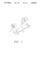
- FIG. 5is an alternative configuration of the feet 28 having a cross-member interconnecting the feet of the two clamping bars.
- the retrofit bracket for a wall mount speaker of the present inventionis illustrated in FIGS. 1-5, which depict a presently preferred embodiment of the invention.
- the retrofit bracket of the present inventiongenerally comprises a bracket or support surface 10 attached to the outside of a wall covering 12 and a plurality, preferably two, of generally parallel elongate clamping bars 14 disposed on the inside of the wall covering such that the wall covering 12 is clamped between the support surface 10 and clamping bars 14.
- Adjustable attachment means or screws 16pass through apertures 18 formed in the bracket support surface 10 and through aperture 20 formed in the wall covering 12 to threadably attach to clamping bars 14.
- Those skilled in the artwill recognize that various other means for adjustably attaching the support surface 10 to the clamping bars 14 are likewise suitable. It is only necessary that the distance between support surface 10 and the clamping bars 14 be adjustable such that the wall surface 12 is clampably capturable therebetween.
- the support surface 10is configured to receive at least one speaker. It comprises a bezel 21 sized to cover the aperture 20 formed within the wall covering 12 and preferably further comprises a grille 22 to cover the speakers. The grille preferably covers and obscures from view the apertures 18 and the screws 16.
- the support surfacepreferably further comprises insertion member 24 received within aperture 20 formed in the wall covering 12. The insertion number 24 is configured in a complimentary fashion to aperture 20, i.e., rectangularly configured for a rectangular aperture.
- each clamping barcomprises a bowed elongate member 26 and feet 28 formed at either end thereof.
- the feet 28flare or increase the contact area of the bowed elongate member 26 such that the force applied thereby to the wall covering 12 is spread over an increased surface area. Compression of the wall covering 12 is thus substantially mitigated.
- the bowed elongate member 26is preferably arched outward, away from the bracket support surface 10 such that tightening of the screws 16 results in deformation, preferably straightening, thereof.
- the bowed elongate 26is formed of a sufficiently resilient material that such straightening thereof results in spring pressure being applied to the wall covering 12 by the feet 28.
- Each clamping bar 14further comprises a plurality of threaded apertures 30 which receive the adjustment means or screws 16 prior to attachment thereof to the support surface 10 and which effect clamping of the present invention to the wall covering 12.
- a number of such threaded apertures 30 in excess of that required for any particular mountingmay be provided to accommodate variations in the configuration of the support surface 10. That is, extra threaded apertures 30 may be provided to accommodate various placements of the apertures 18 in the support surface 10, thus allowing the bracket to be used with various different support surfaces 10.
- the contact surfaces 32 of the feet 28optionally comprise gripping means, preferably configured as a plurality of pointed members 34.
- Such pointed members 34dig into the inside of the inner surface of the wall covering 12 and thus prevent slippage of the clamping bars 14 after they have been tightened.
- the gripping meansmay alternatively comprise either horizontally or vertically configured saw-toothed grippers 36.
- the gripping meansmay alternatively comprise either horizontally or vertically configured saw-toothed grippers 36.
- various other configurationsi.e., knurling, roughened surfaces, etc., are likewise suitable for use as such gripping means.
- an alternative configuration of the feet 52utilizes a cross-member 50 to interconnect each of the adjacent feet 52 of the two bowed elongate members 26.
- the cross-member 50both stabilizes the two bowed elongate members 26 and also provides increased surface area for improved gripping.
- the increased surface area provided by cross-member 50is particularly advantageous in those conditions wherein the inner surface of the wallboard has become slippery, i.e., from wetting, chalk dust, crumbling, etc.
- improved grippingis provided via the use of cross-member 50.
- Cross-member 50attaches to the feet 52 via male members or detents 54 formed upon the cross-member 50 and complimentary female members or detents 56 formed upon the feet 52.
- male members or detents 54formed upon the cross-member 50
- complimentary female members or detents 56formed upon the feet 52.
- the male member 54 and complimentary female members 56are preferably frusto-conical in configuration.
- various configurations of detentsmay be formed thereon to assure positive engagement of the cross-member 50 to the feet 52.
- cross-bar 50further facilitates the use of smaller feet 52 such that the clamping bars 14 may be easily inserted within the opening formed in the wallboard.
- Various gripping surfacesmay be formed upon the wall contact surface of the cross-member 50 to further enhance its ability to grip the inner surface of the wallboard.
- the serrations of the foot 28 illustrated in FIG. 4 or the pointed members of the foot 28 illustrated in FIG. 3may be formed upon the surface of the cross-member 50 which contacts the inner surface of the wallboard.
- One or more speakersare first attached to the bracket support surface 10.
- the clamp barsare then loosely attached to the bracket support surface 10 by passing screws 16 through apertures 18 formed therein and threading the screw 16 into the threaded apertures 30 of the clamping bars.
- the cross-members 50are attached to the feet 52, generally perpendicular to the bowed elongate members 26.
- One cross-member 50is preferably attached to the two lower feet 52 and another cross-member 50 is preferably attached to the upper feet 52 such that two cross-members 50 are utilized, thereby maximizing the ability of the retrofit bracket of the present invention to grip the wall covering.
- One end, i.e., the top, of the clamping bars 14is inserted through the aperture 20 formed in the wall covering 12 and the support surface 10 is then positioned so as to facilitate entry of the opposite end of the clamping bars 14 through the aperture 20.
- the opposite end of the clamping bars 14is then pushed through the aperture 20 and the support surface 10 manipulated to position the feet 28 of the clamping bars 14 such that the wall covering 12 is captured intermediate the feet 28 and the bezel 21.
- the screws 16are then tightened sufficiently to capture or clamp the wall covering 12 therebetween.
- Pointed grippers 34(FIG. 3) or saw-toothed grippers 36 (FIG. 4) formed upon the contact surface 32 of feet 28 may alternatively maintain positioning of the retro fit bracket by preventing sliding of the feet 28 once the adjustment means or screw 16 have been tightened.
- the exemplary retrofit bracket for a wall mount speaker described herein and shown in the drawingsrepresents only a presently preferred embodiment of the invention. Indeed, various modifications and additions may be made to such an embodiment without departing from the spirit and scope of the invention.
- the bowed elongate member 28need not be any particular cross sectional configuration, but rather may be of any cross sectional configuration which provides sufficient resiliency to maintain clamping force as the wall surface compresses.
- feetneed not be angular as illustrated, but rather may be of any shape or configuration which facilitates spreading of the force supplied by the clamping bar 14 over an increased surface area.
Landscapes
- Physics & Mathematics (AREA)
- Engineering & Computer Science (AREA)
- Acoustics & Sound (AREA)
- Signal Processing (AREA)
- Finishing Walls (AREA)
Abstract
Description
Claims (20)
Priority Applications (2)
| Application Number | Priority Date | Filing Date | Title |
|---|---|---|---|
| US08/054,082US5292092A (en) | 1993-04-26 | 1993-04-26 | Retrofit bracket for wall mount speakers |
| US08/148,653US5299766A (en) | 1993-04-26 | 1993-11-05 | Retrofit bracket for wall mount speakers |
Applications Claiming Priority (1)
| Application Number | Priority Date | Filing Date | Title |
|---|---|---|---|
| US08/054,082US5292092A (en) | 1993-04-26 | 1993-04-26 | Retrofit bracket for wall mount speakers |
Related Child Applications (1)
| Application Number | Title | Priority Date | Filing Date |
|---|---|---|---|
| US08/148,653ContinuationUS5299766A (en) | 1993-04-26 | 1993-11-05 | Retrofit bracket for wall mount speakers |
Publications (1)
| Publication Number | Publication Date |
|---|---|
| US5292092Atrue US5292092A (en) | 1994-03-08 |
Family
ID=21988691
Family Applications (2)
| Application Number | Title | Priority Date | Filing Date |
|---|---|---|---|
| US08/054,082Expired - LifetimeUS5292092A (en) | 1993-04-26 | 1993-04-26 | Retrofit bracket for wall mount speakers |
| US08/148,653Expired - LifetimeUS5299766A (en) | 1993-04-26 | 1993-11-05 | Retrofit bracket for wall mount speakers |
Family Applications After (1)
| Application Number | Title | Priority Date | Filing Date |
|---|---|---|---|
| US08/148,653Expired - LifetimeUS5299766A (en) | 1993-04-26 | 1993-11-05 | Retrofit bracket for wall mount speakers |
Country Status (1)
| Country | Link |
|---|---|
| US (2) | US5292092A (en) |
Cited By (17)
| Publication number | Priority date | Publication date | Assignee | Title |
|---|---|---|---|---|
| US5388795A (en)* | 1993-05-25 | 1995-02-14 | Dana Innovations | Depth adjustable bracket for wall mount speakers |
| US6116461A (en)* | 1998-05-29 | 2000-09-12 | Pyxis Corporation | Method and apparatus for the dispensing of drugs |
| US6360842B1 (en) | 2000-02-29 | 2002-03-26 | Multi Service Corporation | In-wall speaker mounting apparatus |
| US6550570B2 (en) | 2001-01-16 | 2003-04-22 | Multi Service Corporation | Speaker enclosure and mounting method for isolating and insulating faceplate and speakers from a surrounding mounting surface |
| US20030123679A1 (en)* | 2002-01-02 | 2003-07-03 | Dudleston William R. | In-wall loudspeaker |
| US20040179710A1 (en)* | 2002-12-20 | 2004-09-16 | Farinelli Robert P. | Audio speaker system |
| US20060052097A1 (en)* | 2004-09-09 | 2006-03-09 | Scott Struthers | I-Port controller |
| US20070051862A1 (en)* | 2005-09-08 | 2007-03-08 | Monti Daniel J | Frameless compression component mounts and quick release speaker frames |
| US20070242137A1 (en)* | 1995-02-23 | 2007-10-18 | Mckain James A | Combined editing system and digital moving picture recording system |
| US20080075297A1 (en)* | 2006-09-11 | 2008-03-27 | Dana Innovations | Devices And Methods For Flangeless Installations |
| US20080224006A1 (en)* | 2007-03-12 | 2008-09-18 | Dana Innovations | Mounting System For Flush Assembly in Walls and Ceilings in Walls And Ceilings |
| US20090193724A1 (en)* | 2006-09-11 | 2009-08-06 | Scott Struthers | Flush Mounting Apparatus And Methods Using Component Cover |
| US20110138739A1 (en)* | 2006-09-11 | 2011-06-16 | Scott Struthers | Devices And Methods For Flangeless Installations |
| US20120080260A1 (en)* | 2008-06-27 | 2012-04-05 | Rgb Systems, Inc. | Ceiling speaker assembly |
| US8839578B2 (en) | 2006-09-11 | 2014-09-23 | Dana Innovations | Flush mount panels with multiple aligned receiving brackets |
| USD713828S1 (en)* | 2012-06-12 | 2014-09-23 | Peerless Industries, Inc. | In-wall adapter box for use with audio/visual mounting systems |
| USD980736S1 (en)* | 2022-08-25 | 2023-03-14 | Yan Teng | Doorbell bracket |
Families Citing this family (7)
| Publication number | Priority date | Publication date | Assignee | Title |
|---|---|---|---|---|
| USD440221S1 (en) | 2000-08-11 | 2001-04-10 | Mcgurty Howard J. | Wall speaker |
| EP1322134B1 (en)* | 2001-12-19 | 2018-12-05 | InterDigital Madison Patent Holdings | Electronic device comprising a loudspeaker |
| US6830275B2 (en) | 2002-11-27 | 2004-12-14 | Brian J. Shea | Speaker mounted in recreational vehicle |
| AU2004202627B2 (en)* | 2003-06-20 | 2009-10-01 | Altronic Distributors Pty Ltd | Speaker Mount Assembly |
| US8270651B2 (en)* | 2004-02-24 | 2012-09-18 | Ksc Industries, Inc. | System and method for mounting of audio-visual components |
| US8064629B2 (en)* | 2007-09-27 | 2011-11-22 | Peigen Jiang | Decorative loudspeaker grille |
| EP4593658A1 (en)* | 2022-09-29 | 2025-08-06 | Christopher P. Fleming | Laptop bracket |
Citations (28)
| Publication number | Priority date | Publication date | Assignee | Title |
|---|---|---|---|---|
| US2522859A (en)* | 1948-01-30 | 1950-09-19 | Gordon S Carbonneau | Electrodynamic loudspeaker and mounting therefor |
| US2604285A (en)* | 1950-03-15 | 1952-07-22 | Gerity Michigan Corp | Fixture holding means |
| US3180595A (en)* | 1962-03-29 | 1965-04-27 | Ra Ma Company Inc | Wall fixture mounting |
| US3327984A (en)* | 1965-05-26 | 1967-06-27 | Robert D Rennie | Device for mounting recessed fixtures |
| US3369784A (en)* | 1966-01-12 | 1968-02-20 | Motorola Inc | Mounting assembly |
| US3664615A (en)* | 1969-08-21 | 1972-05-23 | Smithcraft Corp | Ceiling fixture support |
| US3727004A (en)* | 1967-12-04 | 1973-04-10 | Bose Corp | Loudspeaker system |
| US3912865A (en)* | 1973-07-13 | 1975-10-14 | American Trading & Prod | Loudspeaker arrangement |
| US4133975A (en)* | 1975-04-02 | 1979-01-09 | Bose Corporation | Loudspeaker system with broad image source with directionality control for the tweeter |
| US4250540A (en)* | 1979-08-23 | 1981-02-10 | Mcgraw-Edison Co. | Mounting arrangement for recessed light fixture housing |
| US4266092A (en)* | 1975-04-02 | 1981-05-05 | Bose Products, Inc. | Loudspeaker system with broad image source |
| US4439643A (en)* | 1979-04-02 | 1984-03-27 | Rene Schweizer | System assembly for mounting electrical apparatus on walls and ceilings |
| US4444369A (en)* | 1982-09-07 | 1984-04-24 | Essex Group, Inc. | Mounting ring |
| US4546850A (en)* | 1984-03-12 | 1985-10-15 | Chrysler Corporation | Speaker and grille installation clip mounting |
| US4614374A (en)* | 1984-02-21 | 1986-09-30 | Lyon Metal Products, Incorporated | Recessed latch housing |
| US4688596A (en)* | 1986-06-05 | 1987-08-25 | Research Products Corporation | Wall outlet box for central vacuum cleaning system |
| US4727587A (en)* | 1986-07-24 | 1988-02-23 | Harris Corp. | Acoustical transducer mounting arrangement |
| US4760510A (en)* | 1987-05-18 | 1988-07-26 | Lahti Uolevi L | Simple mounting for electrical fixture |
| US4778134A (en)* | 1987-08-20 | 1988-10-18 | Dana Innovations | Speaker wall bracket |
| US4815558A (en)* | 1985-11-23 | 1989-03-28 | U.S. Philips Corp. | Device for accomodating a loudspeaker into a cut-out of a sound panel |
| US4853966A (en)* | 1987-10-29 | 1989-08-01 | Skrzycki Gary E | Speaker mounting system |
| US4961226A (en)* | 1987-11-30 | 1990-10-02 | Bose Corporation | Stereo electroacoustical transducing |
| US5027403A (en)* | 1988-11-21 | 1991-06-25 | Bose Corporation | Video sound |
| US5082083A (en)* | 1990-10-02 | 1992-01-21 | Culver Electronic Sales, Inc. | Structure wall mounted speaker assembly |
| US5088574A (en)* | 1990-04-16 | 1992-02-18 | Kertesz Iii Emery | Ceiling speaker system |
| US5143339A (en)* | 1991-03-01 | 1992-09-01 | Jbl, Incorporated | Speaker mounting assembly |
| US5205755A (en)* | 1992-03-31 | 1993-04-27 | Amp Incorporated | Float mount electrical connector |
| US5221069A (en)* | 1992-05-12 | 1993-06-22 | Dana Innovations | Telescoping support bracket |
- 1993
- 1993-04-26USUS08/054,082patent/US5292092A/ennot_activeExpired - Lifetime
- 1993-11-05USUS08/148,653patent/US5299766A/ennot_activeExpired - Lifetime
Patent Citations (28)
| Publication number | Priority date | Publication date | Assignee | Title |
|---|---|---|---|---|
| US2522859A (en)* | 1948-01-30 | 1950-09-19 | Gordon S Carbonneau | Electrodynamic loudspeaker and mounting therefor |
| US2604285A (en)* | 1950-03-15 | 1952-07-22 | Gerity Michigan Corp | Fixture holding means |
| US3180595A (en)* | 1962-03-29 | 1965-04-27 | Ra Ma Company Inc | Wall fixture mounting |
| US3327984A (en)* | 1965-05-26 | 1967-06-27 | Robert D Rennie | Device for mounting recessed fixtures |
| US3369784A (en)* | 1966-01-12 | 1968-02-20 | Motorola Inc | Mounting assembly |
| US3727004A (en)* | 1967-12-04 | 1973-04-10 | Bose Corp | Loudspeaker system |
| US3664615A (en)* | 1969-08-21 | 1972-05-23 | Smithcraft Corp | Ceiling fixture support |
| US3912865A (en)* | 1973-07-13 | 1975-10-14 | American Trading & Prod | Loudspeaker arrangement |
| US4133975A (en)* | 1975-04-02 | 1979-01-09 | Bose Corporation | Loudspeaker system with broad image source with directionality control for the tweeter |
| US4266092A (en)* | 1975-04-02 | 1981-05-05 | Bose Products, Inc. | Loudspeaker system with broad image source |
| US4439643A (en)* | 1979-04-02 | 1984-03-27 | Rene Schweizer | System assembly for mounting electrical apparatus on walls and ceilings |
| US4250540A (en)* | 1979-08-23 | 1981-02-10 | Mcgraw-Edison Co. | Mounting arrangement for recessed light fixture housing |
| US4444369A (en)* | 1982-09-07 | 1984-04-24 | Essex Group, Inc. | Mounting ring |
| US4614374A (en)* | 1984-02-21 | 1986-09-30 | Lyon Metal Products, Incorporated | Recessed latch housing |
| US4546850A (en)* | 1984-03-12 | 1985-10-15 | Chrysler Corporation | Speaker and grille installation clip mounting |
| US4815558A (en)* | 1985-11-23 | 1989-03-28 | U.S. Philips Corp. | Device for accomodating a loudspeaker into a cut-out of a sound panel |
| US4688596A (en)* | 1986-06-05 | 1987-08-25 | Research Products Corporation | Wall outlet box for central vacuum cleaning system |
| US4727587A (en)* | 1986-07-24 | 1988-02-23 | Harris Corp. | Acoustical transducer mounting arrangement |
| US4760510A (en)* | 1987-05-18 | 1988-07-26 | Lahti Uolevi L | Simple mounting for electrical fixture |
| US4778134A (en)* | 1987-08-20 | 1988-10-18 | Dana Innovations | Speaker wall bracket |
| US4853966A (en)* | 1987-10-29 | 1989-08-01 | Skrzycki Gary E | Speaker mounting system |
| US4961226A (en)* | 1987-11-30 | 1990-10-02 | Bose Corporation | Stereo electroacoustical transducing |
| US5027403A (en)* | 1988-11-21 | 1991-06-25 | Bose Corporation | Video sound |
| US5088574A (en)* | 1990-04-16 | 1992-02-18 | Kertesz Iii Emery | Ceiling speaker system |
| US5082083A (en)* | 1990-10-02 | 1992-01-21 | Culver Electronic Sales, Inc. | Structure wall mounted speaker assembly |
| US5143339A (en)* | 1991-03-01 | 1992-09-01 | Jbl, Incorporated | Speaker mounting assembly |
| US5205755A (en)* | 1992-03-31 | 1993-04-27 | Amp Incorporated | Float mount electrical connector |
| US5221069A (en)* | 1992-05-12 | 1993-06-22 | Dana Innovations | Telescoping support bracket |
Non-Patent Citations (2)
| Title |
|---|
| Boston Acoustics brochure for Designer Series In Wall Loudspeaker Systems dated 1991.* |
| Boston Acoustics brochure for Designer Series In-Wall Loudspeaker Systems dated 1991. |
Cited By (31)
| Publication number | Priority date | Publication date | Assignee | Title |
|---|---|---|---|---|
| US5388795A (en)* | 1993-05-25 | 1995-02-14 | Dana Innovations | Depth adjustable bracket for wall mount speakers |
| US20070242137A1 (en)* | 1995-02-23 | 2007-10-18 | Mckain James A | Combined editing system and digital moving picture recording system |
| US6116461A (en)* | 1998-05-29 | 2000-09-12 | Pyxis Corporation | Method and apparatus for the dispensing of drugs |
| US6338007B1 (en) | 1998-05-29 | 2002-01-08 | Pyxis Corporation | System and apparatus for the storage and dispensing of items |
| US6360842B1 (en) | 2000-02-29 | 2002-03-26 | Multi Service Corporation | In-wall speaker mounting apparatus |
| US6415886B1 (en)* | 2000-02-29 | 2002-07-09 | Multi Service Corporation | In-wall speaker mounting apparatus |
| US6550570B2 (en) | 2001-01-16 | 2003-04-22 | Multi Service Corporation | Speaker enclosure and mounting method for isolating and insulating faceplate and speakers from a surrounding mounting surface |
| US20030123679A1 (en)* | 2002-01-02 | 2003-07-03 | Dudleston William R. | In-wall loudspeaker |
| US20040179710A1 (en)* | 2002-12-20 | 2004-09-16 | Farinelli Robert P. | Audio speaker system |
| US7792524B2 (en) | 2004-09-09 | 2010-09-07 | Dana Innovations | iPort controller |
| US7493142B2 (en) | 2004-09-09 | 2009-02-17 | Dana Innovations | I-port controller |
| US7929961B2 (en) | 2004-09-09 | 2011-04-19 | Dana Innovations | Wall mounted docking station |
| US7155214B2 (en) | 2004-09-09 | 2006-12-26 | Dana Innovations | I-port controller |
| US20080018490A1 (en)* | 2004-09-09 | 2008-01-24 | Dana Innovations | Iport controller |
| US20060052097A1 (en)* | 2004-09-09 | 2006-03-09 | Scott Struthers | I-Port controller |
| US20070036384A1 (en)* | 2004-09-09 | 2007-02-15 | Scott Struthers | I-port controller |
| US7455272B2 (en) | 2005-09-08 | 2008-11-25 | Architectural Audio/Video | Frameless compression component mounts and quick release speaker frames |
| US20070051862A1 (en)* | 2005-09-08 | 2007-03-08 | Monti Daniel J | Frameless compression component mounts and quick release speaker frames |
| US8245453B2 (en) | 2006-09-11 | 2012-08-21 | Dana Innovatoions | Flush mounting apparatus and methods using component cover |
| US20090193724A1 (en)* | 2006-09-11 | 2009-08-06 | Scott Struthers | Flush Mounting Apparatus And Methods Using Component Cover |
| US7699138B2 (en)* | 2006-09-11 | 2010-04-20 | Dana Innovations | Devices and methods for flangeless installations |
| US8839578B2 (en) | 2006-09-11 | 2014-09-23 | Dana Innovations | Flush mount panels with multiple aligned receiving brackets |
| US20080075297A1 (en)* | 2006-09-11 | 2008-03-27 | Dana Innovations | Devices And Methods For Flangeless Installations |
| US20110138739A1 (en)* | 2006-09-11 | 2011-06-16 | Scott Struthers | Devices And Methods For Flangeless Installations |
| US8250830B2 (en) | 2006-09-11 | 2012-08-28 | Dana Innovations | Devices and methods for flangeless installations |
| US20080224006A1 (en)* | 2007-03-12 | 2008-09-18 | Dana Innovations | Mounting System For Flush Assembly in Walls and Ceilings in Walls And Ceilings |
| US20120080260A1 (en)* | 2008-06-27 | 2012-04-05 | Rgb Systems, Inc. | Ceiling speaker assembly |
| US8297402B2 (en)* | 2008-06-27 | 2012-10-30 | Rgb Systems, Inc. | Ceiling speaker assembly |
| WO2010090828A2 (en) | 2009-01-20 | 2010-08-12 | Dana Innovations | Flush mounting apparatus and methods using component cover |
| USD713828S1 (en)* | 2012-06-12 | 2014-09-23 | Peerless Industries, Inc. | In-wall adapter box for use with audio/visual mounting systems |
| USD980736S1 (en)* | 2022-08-25 | 2023-03-14 | Yan Teng | Doorbell bracket |
Also Published As
| Publication number | Publication date |
|---|---|
| US5299766A (en) | 1994-04-05 |
Similar Documents
| Publication | Publication Date | Title |
|---|---|---|
| US5292092A (en) | Retrofit bracket for wall mount speakers | |
| US5405111A (en) | Bracket for anchoring apparatus between wall studs | |
| US4062512A (en) | Clamp for securing bar hanger to electrical wiring box | |
| US6931794B1 (en) | Method and apparatus for installing fitting | |
| JP2961365B1 (en) | Suspension support device and its upper mounting device, detachment prevention device, and oblique support device | |
| KR20210029705A (en) | Fixing device for wall-mounted display mount | |
| US6033129A (en) | Camera mounting plate and lock | |
| JP3399633B2 (en) | Mounting bracket for electronic equipment housing | |
| AU2006228079B2 (en) | Mounting assembly for an electrical power outlet or alike | |
| KR101498585B1 (en) | Holding device for speaker | |
| JP2736766B2 (en) | Fixing tool | |
| JP3526423B2 (en) | Panel mounting bracket for temporary enclosure | |
| GB2431542A (en) | Anchor structure for a fire-proof steel frame of a ceiling speaker | |
| US20060284024A1 (en) | Audio component mounting assembly | |
| JPS5846163Y2 (en) | panel mounting device | |
| JPH0721035Y2 (en) | Speaker unit mounting structure | |
| JPH0835689A (en) | Outdoor unit installation device for air conditioner | |
| JP3016281U (en) | Shelf mount | |
| JPS597817Y2 (en) | Front frame mounting device | |
| JPS6246390Y2 (en) | ||
| KR20230018958A (en) | Electric Wiring Equipment Support | |
| JP2960871B2 (en) | Accordion curtain handle | |
| JPH0739134Y2 (en) | Mounting device for hanging bolts | |
| JP4004351B2 (en) | Panel fixing bracket | |
| JPS6121907Y2 (en) |
Legal Events
| Date | Code | Title | Description |
|---|---|---|---|
| AS | Assignment | Owner name:DANA INNOVATIONS, CALIFORNIA Free format text:ASSIGNMENT OF ASSIGNORS INTEREST;ASSIGNORS:CURTIS, JERRY;KINDEL, WILLIAM J.;SPENCER, GEOFFREY L.;AND OTHERS;REEL/FRAME:006546/0611 Effective date:19930421 | |
| STPP | Information on status: patent application and granting procedure in general | Free format text:APPLICATION UNDERGOING PREEXAM PROCESSING | |
| FPAY | Fee payment | Year of fee payment:4 | |
| FPAY | Fee payment | Year of fee payment:8 | |
| FPAY | Fee payment | Year of fee payment:12 | |
| AS | Assignment | Owner name:UNION BANK OF CALIFORNIA, N.A.,CALIFORNIA Free format text:SECURITY AGREEMENT;ASSIGNOR:DANA INNOVATIONS;REEL/FRAME:018480/0556 Effective date:20061018 Owner name:UNION BANK OF CALIFORNIA, N.A., CALIFORNIA Free format text:SECURITY AGREEMENT;ASSIGNOR:DANA INNOVATIONS;REEL/FRAME:018480/0556 Effective date:20061018 | |
| AS | Assignment | Owner name:DANA INNOVATIONS, CALIFORNIA Free format text:RELEASE BY SECURED PARTY;ASSIGNOR:MUFG UNION BANK, N.A.;REEL/FRAME:060257/0622 Effective date:20220616 |