US5291262A - Laser surveying instrument - Google Patents
Laser surveying instrumentDownload PDFInfo
- Publication number
- US5291262A US5291262AUS07/914,764US91476492AUS5291262AUS 5291262 AUS5291262 AUS 5291262AUS 91476492 AUS91476492 AUS 91476492AUS 5291262 AUS5291262 AUS 5291262A
- Authority
- US
- United States
- Prior art keywords
- pulse
- target
- ref
- interpolation
- time
- Prior art date
- Legal status (The legal status is an assumption and is not a legal conclusion. Google has not performed a legal analysis and makes no representation as to the accuracy of the status listed.)
- Expired - Lifetime
Links
- 238000004458analytical methodMethods0.000claimsdescription21
- 238000010304firingMethods0.000claimsdescription11
- 230000000630rising effectEffects0.000claimsdescription11
- 230000015654memoryEffects0.000claimsdescription9
- 238000000034methodMethods0.000claimsdescription8
- 238000001514detection methodMethods0.000claimsdescription7
- 238000012545processingMethods0.000claimsdescription7
- 230000004044responseEffects0.000claimsdescription7
- 230000008569processEffects0.000claimsdescription6
- 230000000737periodic effectEffects0.000claimsdescription5
- 230000009977dual effectEffects0.000abstract1
- 238000005259measurementMethods0.000description17
- 239000003990capacitorSubstances0.000description13
- 230000003321amplificationEffects0.000description4
- 238000012937correctionMethods0.000description4
- 238000010586diagramMethods0.000description4
- 238000003199nucleic acid amplification methodMethods0.000description4
- 230000003750conditioning effectEffects0.000description3
- XUIMIQQOPSSXEZ-UHFFFAOYSA-NSiliconChemical compound[Si]XUIMIQQOPSSXEZ-UHFFFAOYSA-N0.000description2
- 238000010276constructionMethods0.000description2
- 239000013078crystalSubstances0.000description2
- 238000013461designMethods0.000description2
- 230000000694effectsEffects0.000description2
- 230000006870functionEffects0.000description2
- 230000035945sensitivityEffects0.000description2
- 229910052710siliconInorganic materials0.000description2
- 239000010703siliconSubstances0.000description2
- 238000006467substitution reactionMethods0.000description2
- 238000012935AveragingMethods0.000description1
- 230000004913activationEffects0.000description1
- 239000000654additiveSubstances0.000description1
- 230000000996additive effectEffects0.000description1
- 230000008859changeEffects0.000description1
- 239000003795chemical substances by applicationSubstances0.000description1
- 239000011521glassSubstances0.000description1
- 230000006872improvementEffects0.000description1
- 238000010348incorporationMethods0.000description1
- 238000004519manufacturing processMethods0.000description1
- 238000013507mappingMethods0.000description1
- 239000003550markerSubstances0.000description1
- 238000012986modificationMethods0.000description1
- 230000004048modificationEffects0.000description1
- 230000003287optical effectEffects0.000description1
- 230000010363phase shiftEffects0.000description1
- 238000005070samplingMethods0.000description1
- 239000004065semiconductorSubstances0.000description1
- 230000000007visual effectEffects0.000description1
- 230000003936working memoryEffects0.000description1
Images


Classifications
- G—PHYSICS
- G01—MEASURING; TESTING
- G01C—MEASURING DISTANCES, LEVELS OR BEARINGS; SURVEYING; NAVIGATION; GYROSCOPIC INSTRUMENTS; PHOTOGRAMMETRY OR VIDEOGRAMMETRY
- G01C15/00—Surveying instruments or accessories not provided for in groups G01C1/00 - G01C13/00
- G01C15/002—Active optical surveying means
- G—PHYSICS
- G01—MEASURING; TESTING
- G01S—RADIO DIRECTION-FINDING; RADIO NAVIGATION; DETERMINING DISTANCE OR VELOCITY BY USE OF RADIO WAVES; LOCATING OR PRESENCE-DETECTING BY USE OF THE REFLECTION OR RERADIATION OF RADIO WAVES; ANALOGOUS ARRANGEMENTS USING OTHER WAVES
- G01S17/00—Systems using the reflection or reradiation of electromagnetic waves other than radio waves, e.g. lidar systems
- G01S17/02—Systems using the reflection of electromagnetic waves other than radio waves
- G01S17/06—Systems determining position data of a target
- G01S17/08—Systems determining position data of a target for measuring distance only
- G01S17/10—Systems determining position data of a target for measuring distance only using transmission of interrupted, pulse-modulated waves
- G01S17/14—Systems determining position data of a target for measuring distance only using transmission of interrupted, pulse-modulated waves wherein a voltage or current pulse is initiated and terminated in accordance with the pulse transmission and echo reception respectively, e.g. using counters
- G—PHYSICS
- G01—MEASURING; TESTING
- G01S—RADIO DIRECTION-FINDING; RADIO NAVIGATION; DETERMINING DISTANCE OR VELOCITY BY USE OF RADIO WAVES; LOCATING OR PRESENCE-DETECTING BY USE OF THE REFLECTION OR RERADIATION OF RADIO WAVES; ANALOGOUS ARRANGEMENTS USING OTHER WAVES
- G01S17/00—Systems using the reflection or reradiation of electromagnetic waves other than radio waves, e.g. lidar systems
- G01S17/02—Systems using the reflection of electromagnetic waves other than radio waves
- G01S17/50—Systems of measurement based on relative movement of target
- G01S17/58—Velocity or trajectory determination systems; Sense-of-movement determination systems
- G—PHYSICS
- G01—MEASURING; TESTING
- G01S—RADIO DIRECTION-FINDING; RADIO NAVIGATION; DETERMINING DISTANCE OR VELOCITY BY USE OF RADIO WAVES; LOCATING OR PRESENCE-DETECTING BY USE OF THE REFLECTION OR RERADIATION OF RADIO WAVES; ANALOGOUS ARRANGEMENTS USING OTHER WAVES
- G01S17/00—Systems using the reflection or reradiation of electromagnetic waves other than radio waves, e.g. lidar systems
- G01S17/86—Combinations of lidar systems with systems other than lidar, radar or sonar, e.g. with direction finders
Definitions
- the inventionrelates generally to surveying devices and more particularly to a laser surveying device.
- Surveying devicesare available to serve various purposes, including topographical mapping, surveying to determine property boundaries, etc. Such devices usually include a sight, a compass and an inclinometer for ascertaining the direction and the angle of inclination from the surveyor's position, of the landmark whose location is being determined.
- two personsare required: a first positioned at the landmark itself, and a second at a known distance from the landmark taking readings.
- the second personsights on the first person, and takes readings from the compass and inclinometer.
- the necessary calculationsare based on the known distance between the landmark and the surveyor, the compass heading and the inclination.
- the first personthen moves to another location, and the process is repeated. Readings from at least three different locations are needed to establish the location of the landmark.
- a laser light spotis projected against a target which may be an inanimate target placed by the surveyor who then takes readings from a known distance (for example, see U.S. Pat. Nos. 4,029,415 to Johnson, 4,873,449 to Paramythioti, and 4,673,287 to Rickus).
- Proper sighting by the surveyormay be established by receipt of a reflected pulse from the target, by visual observation of laser light on the target, or by a signal provided by the target upon its being struck by the laser beam.
- the distance between the surveyor and the targetis established from laser light reflected by the target and received by a detector in the surveyor's unit.
- laser distance measurementshave also been employed for surveying, determining the speed of objects or vehicles, etc, as illustrated in U.S. Pat. Nos. 3,464,770 to Schmidt et al, 4,902,889 to Sodi, and 3,698,811 to Weil.
- Such improved laser distance measuring deviceseliminate the need for the surveyor to physically measure the distance to the target.
- An electronic surveying systemis disclosed in U.S. Pat. Nos. 4,146,927 and 4,205,385, both to Erickson et al.
- the systemincludes a theodolite which provides data in a digital output form, an electronic distance-finding device, a tilt sensor, and computing means interfacing with these elements to make survey calculations.
- the electronic distance-finderis a phase-shift analysis type of instrument which requires a reflective marker attached to the survey target to achieve adequate return signal strength for the phase analysis.
- a theodolitemust be fixedly mounted, for example on a tripod, and referenced to two known survey points, in order to make measurements. Thus, it is very cumbersome to make measurements at numerous different and remote locations.
- a needremains for a laser survey device which is accurate, conveniently portable, and does not require known reference points for calibration of distance or compass heading, or mounting on a fixed structure such as a tripod.
- a needfurther remains for such a device which does not require attachment of a target sensor or other device to the target whose distance is to be determined.
- such a systemwould measure and digitally input directly to an internal computer, readings of distance, compass heading and inclination.
- the inventioncomprises a laser survey instrument including at least the following components: a laser rangefinder, a magnetic compass module constructed to produce an electronically readable compass signal, a vertical angle sensor module which is constructed to produce an electronically readable vertical angle signal, and a microprocessor-based microcontroller which is controllingly and communicatively interconnected to the foregoing components.
- the instrumentis small enough to be easily hand-held, and further includes a trigger and a sighting scope for a user to visually select a target and to trigger operation of the device upon the selected target.
- the sighting scopeincludes means for measuring the apparent width of the target.
- the survey devicedetermines the distance to a remote target by measuring the time-of-flight of a very short duration pulse of infrared light.
- the laser rangefinderfires the laser pulse, detects reflected laser light, and provides count values reflective of the respective arrival times of a REF (reference) pulse representing the firing time of the laser pulse, and an RX pulse representing reflected laser pulse light.
- the microcontrolleris configured to read these count values and to compute from them, the time-of-flight of the laser pulse and in turn, the distance to the target.
- the vertical angle sensoris presently embodied as a commercially-manufactured electrolytic tilt sensor, which in combination with appropriate signal conditioning circuits, outputs an inclination signal reflective of the vertical angle to the target.
- any other type of vertical angle sensor or inclinometer which provides an electronic-ally readable data output signalmay be used.
- the micro- controlleris operable to use the vertical angle signals in conjunction with the distance data signals provided by the rangefinder, to calculate the height of a remote object such as a tree, truck or the like.
- the magnetic compassis constructed to make a reading of the compass heading based on magnetic fields, without a requirement for triangulation, affixation to a tripod, or calibration to a known position.
- the magnetic compassis further constructed to provide an electronically readable data signal which can be read, or modified for reading, by the microcontroller.
- a crystal clock-based timing analysis circuitincludes a gating circuit which is a digital logic, edge-sensitive gate for which both the "opening" and the "closing" of the time window can be selectably set by the microcontroller.
- the microcontrolleris configured to alternately widen and narrow the window to selectively lock on "true" RX pulses and exclude pulses due to noise or other factors.
- the timing analysis circuitryis constructed to generate self-calibration pulses and to process them in the same manner as the REF and RX pulses, thereby producing a set of calibration interpolation counts.
- the controlleruses these calibration interpolation counts along with the REF and RX interpolation counts to compute self-calibrated values of the respective fractional portions of the clock periods at which the REF and RX pulses arrived.
- the self-calibration pulsescomprise a pair of pulses, referred to for simplicity as TMIN and TMAX, which differ by a known integral number of clock periods (with neither TMIN nor TMAX being zero). Together, TMIN and TMAX define an expanded interpolation interval within which the fractional portions of the RX and REF arrival times are interpolated. This self-calibrating interpolation provides greatly enhanced resolution and accuracy of distance measurements based on elapsed time.
- the laser rangefinderhas a first collimator which directs a major portion of an outgoing laser pulse toward the selected target, and a second collimator which redirects a minor portion of the laser pulse to produce a timing reference signal.
- the minor portion of the laser pulseis sent to a second light detector separate from a first light detector (here embodied as a silicon avalanche photodiode detector or "APD") which focusses and receives reflected laser light.
- the minor portion of the laser pulseis sent to the same detector which detects the returned laser light.
- the microcontrolleris constructed to direct a user's operation of the survey system according to various modes which include one or more of the following: determination of range distance; determination of location coordinates of a target; determination of the height and/or width of a target object.
- the microcontrollermay be configured to collect height and/or width data for a series of trees in a selected sector, to estimate the board footage or number of logs per tree from the height and width data, etc.
- the usefulness of the survey systemextends to many other types of survey measurements as well.
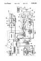
- FIG. 1is a block diagram of a working embodiment of the laser surveying device of the invention
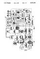
- FIG. 2is a block diagram detailing the laser rangefinder system of FIG. 1;
- FIG. 3is a functional schematic of the gating circuitry of the timing logic of FIG. 2;
- FIG. 4Ais a functional schematic of an embodiment of a pulse stretcher circuit useful as interpolation circuit 250 or 252;
- FIG. 4Bis a functional schematic of an alternate embodiment of a charge pump circuit useful as interpolation circuit 250 or 252;
- FIG. 5is a waveform diagram for pulse stretchers 250, 252;
- FIG. 6is a functional schematic of a timing logic circuit 240
- FIG. 7is a block diagram of an alternate embodiment wherein interpolation circuit 250 is the charge pump circuit of FIG. 4B.
- FIG. 1depicts a working embodiment of the laser surveying device.
- This embodimentincorporates the following basic components: a sighting scope 10 for a user to visually select a target; a keypad 20 and trigger 24 which together comprise user operation means; a laser rangefinding system 30; a vertical angle sensor 40 with an associated temperature sensor 42 and signal processor 44; a magnetic compass 50; a microcontroller 60 including a microprocessor 64 and a communicatively associated memory unit 70; and data output means 80 which is here shown to comprise a display 82 and a UART 84 connectible to provide data to an external computer or data logger.
- Microcontroller 60is communicatively interfaced to send logic commands and to read and store data from, laser rangefinder 30, vertical angle sensor 40 and magnetic compass 50.
- the operations which microcontroller 60 is configured to superviseinclude: sending a laser pulse toward the target to determine its distance; making a compass reading; and determining the angle and direction of tilt. Modes which microcontroller 60 may be configured to control are described in greater detail later herein. In the illustrated embodiment, selection of an operating mode is made by operation of appropriate buttons or the like on keypad 20, which is communicatively connected to the microcontroller.
- Microcontroller 60is also configured to perform various computations with readings acquired from rangefinder subsystem 30, vertical angle sensor 40 and compass 50. Relevant details of these computations are disclosed in a subsequent paragraph of this application.
- Sighting scope 10is provided for a user to select and aim the survey device at a selected target.
- the sighting scopeis operably associated with laser rangefinder 30, vertical angle sensor 40 and magnetic compass 50 such that when a user sights on target 90 with the sighting scope, the laser pulse generator 102, light detector 104, and magnetic compass 50 are simultaneously aimed at the target, and vertical angle sensor 40 outputs a signal reflective of the vertical angle to the target.
- Trigger 24When the survey device is aimed at a target 90, the user then operates trigger 24 to initiate functioning of the survey device in a preselected mode.
- Trigger 24is communicatively connected to send a trigger signal to microprocessor 64.
- microcontroller 60In response to receipt of the trigger signal, microcontroller 60 initiates and supervises the performance of one or a series of operations by the survey device, according to which of a variety of operating modes has been selected.
- sighting scope 10includes means for measuring the apparent width of target 90.
- the width measuring meansis a reticle arranged in sighting scope 10.
- the useraims sighting scope 10 at the target 90, determines the number of reticle markings between the left and right edges of the target, and enters these into microcontroller 60 by means of keypad 20.
- Microcontroller 60is configured to use the reticle marking data in conjunction with the target distance determined by laser rangefinder 30, to compute the actual width of the target, by computations which will be apparent to those skilled in the art of surveying.
- the inclination as measured by vertical angle sensor 40may be included in the computation.
- An alternate embodiment of width measuring means for sighting scope 10is a split-prism lens arrangement similar to those used as focussing aids for cameras.
- the split-prism lensis connected to an adjustment knob associated with a rotary encoder.
- the useroperates the adjustment knob to visually align one edge of the target in the upper half of the split image to the opposite edge in the other lower half of the image.
- the rotary encodergenerates an encoder signal comprising a series of pulses proportional to the angle through which the knob is turned.
- the encoder signalis fed to a counter port of microprocessor 64.
- the rotary encoderalso generates a clockwise/anticlockwise signal and the latter in combination with the encoder signal allows microcontroller 60 to accurately calculate the knob rotation, and thereby the horizontal angle subtended by the target object. The actual width may then be computed as described for the reticle embodiment.
- Vertical angle sensor 40generates a vertical angle signal reflective of the detected vertical angle (the inclination from the horizontal) of target 90.
- vertical angle sensor 40is an electrolytic-type tilt sensor, such as the model L-211 U which is commercially available from Spectron Glass and Electronics, Inc., Hauppage, New York; also available through G+G Technics AG, CH-4419 Lupsingen/BL, Switzerland.
- the indicated electrolytic sensoris obtained from the company without attached means for generating the desired vertical angle data signal. Therefore, a signal conditioner 44 processes the "raw" signal to produce a vertical angle signal readable by microprocessor 60.
- Signal conditioning circuitry 44drives the electrolytic sensor with a square wave drive signal in a balanced bridge configuration.
- Signal conditioning circuitry 44also includes a voltage-to-frequency (V-F) converter which converts the electrolytic sensor output signal 46 to a frequency signal which is sent to a counter/timer port on microprocessor 64.
- Microprocessor 64sets a known sampling period, so that the count received at the counter/timer port is directly proportional to the vertical angle sensed by the electrolytic sensor.
- the electrolytic tilt sensorhas an associated temperature sensor 42. This is because the inclination signal produced by an electrolytic sensor is highly variable with variation in temperature. Temperature sensor 42 communicates with microcontroller 60, which uses the temperature reading in conjunction with a look-up table stored in memory 70, and other means for correcting the output of the electrolytic sensor.
- Microcontroller 60is further configured to compute the height of a remote target from a pair of inclination readings made respectively from the top and bottom of the target, plus the distance to the target acquired via laser rangefinder 30.
- Magnetic compass 50is here selected to be a magnetic fluxgate compass module, model C100 commercially available from KVH Industries, Inc., Middletown, R.I. It is connected to provide a compass data signal to microprocessor 60, essentially as directed by the manufacturer (C100 Electronic Compass Module User's Manual, pub. KVH Industries, Inc, 1991). Power for magnetic compass 50 is supplied by connection to the V2 low-power output of power supply 100.
- the fluxgate compasscomprises a sensor coil assembly having a floating magnetic ring core surrounded by a toroidal drive coil and two orthogonally-disposed detection coils.
- a processing boardcontains all the components needed to drive the sensor, detect the return signals and derive a magnetic compass bearing.
- the compass modulehas an auto-calibration mode which allows a user to correct for errors in compass readings introduced by stray magnetic fields within the survey device.
- Laser rangefinder system 30determines a distance 92 from the survey device to target 90 (distance 92 is schematically depicted along the sightline from sighting scope 10 to target 90).
- Rangefinder system 30includes a high voltage power supply 100 connected to power a laser pulse generator 102 and to provide bias voltage to a light detector 104.
- a first collimator 106is operably associated with laser pulse generator 102 for directing a major portion of an outgoing laser pulse 103 generated by laser pulse generator 102 towards a target 90.
- a second collimator 108is disposed to redirect a minor portion 109 of each outgoing laser pulse 103 to generate a timing reference signal.
- the redirected portion 109is sent to the APD light detector 104, which outputs an analog signal containing information both as to the timing reference pulse and the subsequently-received reflected light pulse.
- the redirected portion 109is sent to a separate light detector, specifically a PIN photodetector 210 which provides a second detector signal constituting the timing reference signal.
- focussing optics 110are operably associated with light detector 104 for focussing received light thereon.
- a bandpass filter 112is desirably associated with focussing optics 110 for ensuring that detector 104 only receives light of wavelengths near the expected wavelength based on the emitted laser pulse.
- bandpass filter 112is a narrow band interference filter.
- Light detector 104is also connected to detector signal processing circuitry 113.
- Operation of the laser rangefinding subsystem 30is controlled by a microcontroller 60 via logic control lines 122 which are connected to laser pulse generator 102 and the detector signal processing circuitry 113.
- the detector signal processing circuitry 113is further connected to provide detector signals reflective of laser light received by light detector 104 to micro controller 120 and associated elements including a memory 70, display 82 and UART 84.
- Memory 70includes both nonvolatile and volatile components, and is configured for nonvolatile storage of instructions for the microcontroller, semipermanent or permanent storage of instrument parameters, look-up tables, and the like; temporary storage of data readings made by the survey system; and a volatile working memory for initialization, numerical manipulations, and the like.
- the laser pulse generatortakes the form of a laser diode 200 having an operably-connected driver, while the light detector is a silicon avalanche photodiode detector 202 (abbreviated hereinafter as APD 202).
- High voltage power supply 100supplies power to laser diode 200 and APD 202 detector 104 via respective linear regulators 201, 203.
- Regulator 201controls the firing voltage of laser diode 200 and regulator 203 controls the bias voltage applied to APD 202.
- Both regulators 201, 203are connected via a D/A converter 205 to microprocessor 64 which controls them to provide the appropriate respective voltages.
- the firing voltageis adjusted so that the laser diode outputs the desired optical power.
- the bias voltageis adjusted so that APD 202 is operated at the desired sensitivity.
- APD 202produces a signal current in response to the receipt of light passing through filter 112. This signal current is passed through amplification means 204 to be amplified and filtered to reject slowly varying interference signals. The amplified detector signal is then sent to a threshold comparator 208. If the amplified detector signal exceeds the preset threshold of comparator 208, it is sent to a gating circuit 212.
- a second photodetector 21Owhich is here embodied as a PIN semiconductor photodetector is disposed to receive the redirected pulse portion 109 of the outgoing laser pulse 103.
- PIN photodetector 210Upon receipt of the redirected pulse portion 109, PIN photodetector 210 generates an analog signal which is sent to amplification means 214 and in turn to a threshold comparator 216.
- the output of threshold comparator 216constitutes a reference signal 218 which represents the time at which the outgoing laser pulse 103 was emitted. Reference signal 218 is sent to timing analysis circuitry 114.
- a temperature sensor 270is disposed to sense the temperature of APD 202 and to provide temperature readings to microcontroller 60. In response to these temperature readings, microcontroller 60 consults a lookup table stored in memory 70 to determine the desired value of bias voltage to be applied to APD 202 and to control regulator 203 to adjust the bias voltage as needed to correspond to the desired value.
- microprocessor 64adjusts the firing voltage applied to laser diode 200 via regulator 201 in accordance with a firing voltage lookup table stored in memory 70.
- Timing analysis circuitry 114which in the embodiment of FIG. 2 comprises gating circuit 212, timing logic 240, clock 242, interpolation circuits 246, 248, interpolation counters 250, 252, and main counter 260, operates to determine the arrival times of the respective rising edges of reference and RX pulses 218, 232, in terms of the number of cycles of clock 242. These count times are temporarily stored in main counter 260 and interpolation counters 250, 252. Microcontroller 60 reads and stores the clock count times from the counters and from these values computes the time-of-flight of the laser pulse. The time-of-flight is divisible by twice the speed of light to give the distance from the survey device to the target.
- a significant feature of the design of timing analysis circuitry 114is its mutual configuration with micro-controller 60 to provide self-calibrated interpolated values of the respective fractional portions of the arrival times within the corresponding clock periods in which reference (REF) and reflected light (RX) pulses 218 and 232 are received. That is, the arrival times of the REF and RX pulses generally fall somewhere within a clock period.
- the true elapsed time between the REF and RX pulsescomprises the number of whole clock periods elapsed, plus the fractional portion of the clock period occurring just after the receipt of the REF pulse and the fractional portion of the clock period occurring just prior to receipt of the RX pulse.
- REF fractional portion and RX fractional portionare the arrival times within the corresponding clock periods in which reference (REF) and reflected light (RX) pulses 218 and 232 are received. That is, the arrival times of the REF and RX pulses generally fall somewhere within a clock period.
- the self-calibrated interpolated arrival timesare obtained by 1) construction of timing logic circuit 240 to process the REF and RX pulses to produce corresponding REF and RX interpolation pulses respectively comprising the REF fractional portion and the RX fractional portion; 2) construction of timing logic circuit 240 to generate a pair of self-calibration pulses TMIN and TMAX which bracket a chosen interpolation width; 3) sending the REF interpolation pulse through a REF interpolation circuit 246 and the RX interpolation pulse through an RX interpolation circuit 248 to produce respectively REF and RX interpolated count values; 4) sending both self-calibration pulses TMIN and TMAX through each of interpolation circuits 246, 248, thereby producing two respective sets of self-calibration values TMIN-REF, TMAX-REF and TMIN-RX, TMAX-RX; and 5) configuration of microcontroller 60 to compute the REF and RX fractional portions from the respective self-calibration values and the appropriate RE
- the design described in the preceding paragraphis particularly advantageous in that it substantially eliminates errors resulting from drift in the interpolation circuits and timing logic or variability of component tolerances.
- the survey device so constructedcan determine distances to a resolution of a few millimeters or less with very high accuracy.
- the arrival timesare here defined as the times at which the respective rising edges of REF and RX pulses 218, 232 are transmitted through the respective threshold comparators 208, 216.
- comparators 208, 216 and/or gating circuit 212any other point present on both REF and RX pulses 218, 232 may be used to represent the arrival times of the pulses.
- Microprocessor 64is connected to set the select lines 294, 296 into multiplexer MUX2 of timing logic 240 (FIG. 6) to control sending of calibration pulses TMIN, TMAX to interpolation circuits 246, 248. Generation of the calibration pulses by timing logic 242 is initiated at least once during each measurement cycle upon operation of the trigger by a user. Preferably, the self-calibration cycle is performed a plurality of times, perhaps 8 or more, per measurement cycle. Microprocessor 64 is also connected to reset all the logic elements in timing analysis circuitry as necessary at the start of each measurement and between production of the TMIN, TMAX calibration pulses and the REF and RX interpolation pulses.
- each measurement cyclecomprises the firing of a plurality of laser pulses at a preset interval (which is significantly longer than the time to receive the reflected pulse light), and averaging the elapsed time between REF and RX pulses for most or all of the plurality of fired pulses.
- timing analysis circuitry 114Specific circuits embodying various elements of timing analysis circuitry 114 are functionally depicted in FIGS. 3, 4A, 4B, and 6.
- Gating circuit 212ensures that only detector pulses produced by APD 202 within a selected time window following emission of laser pulse 103 are accepted as representing returned laser pulse light 105, and sent to the timing logic 240 as RX (return) pulse signal 232 for analysis.
- a detector pulse 206 arriving before or after the selected windowis not transmitted by gating circuit 212 to timing logic 240 and does not receive further processing.
- Gating circuit 212also outputs a digital pulse width signal 233, which is reflective of the width of the RX pulse.
- RX pulse width signal 233is sent to microcontroller 60 via a pulse width measuring circuit 235 and an A/D converter 234, where it is used to derive a correction factor to compensate for saturation of APD 202 and/or the amplification means 204.
- Gating circuit 212is a digital logic-operated gate, in which both the delay time (the time at which the window "opens") and the time at which the window "closes” can be independently selectably set via microprocessor 60, as directed by a user or by a program stored in memory 70. That is, the delay time can be changed with or without a change in the "closing" time, and vice-versa.
- the gateis edge-sensitive, that is, only a detector pulse whose rising edge falls within the window will be accepted and transmitted as an RX pulse. If only the peak or the falling edge of a detector pulse falls within the window, it will be rejected.
- edge-sensitive gate componentsprovides increased accuracy in the selection of RX pulses.
- microcontroller 60is configured to iteratively and independently adjust the times of the opening and/or closing of the gate for a series of laser pulses fired at a single target, to establish a window which accurately defines "true" RX pulses from the target.
- This adjustmentis performed generally as follows: 1) When the first REF pulse in the series arrives at the gate, the window is opened very wide and the delay time is set to be short. If a detector pulse is received within the first window, then 2) when the second REF pulse arrives the window is narrowed and centered on the arrival time of the first detector pulse (by shifting the opening and/or closing time of the window as necessary). If the second detector pulse is not received within the second window, then 3) the window is widened again for the third REF pulse.
- the windowis further narrowed for the fourth REF pulse, and so on.
- the windowmay also be re-centered (the delay time changed) on the average of the receipt times of specified detector pulses.
- the gating circuit with the microcontrollerconfigured as described to vary independently the opening and closing times of the RX window, and to iteratively narrow and widen the RX window, causes the rangefinder to effectively "lock on” to a target, and avoid errors due to detector or circuit noise, or readings made from non-target objects adjacent the selected target. Also, jamming of the laser return signal is very difficult with the survey device so designed.
- gating circuit 212has 2 identical counters 300, 302 which are connected to microcontroller 60 by both logic control lines 122 and the main data buss, such that counters 300, 302 can be selectably set to desired values by microcontroller 60.
- Counters 300, 302are also connected to receive a clock signal from clock 242.
- the REF pulse 218is sent from threshold comparator 216 into both counters 300, 302.
- the output of counter 302is sent through an inverting amplifier 304 and in turn goes to an and gate 306 along with the output of counter 300.
- gate 306outputs a gate control signal 310 which is active (logical 1) when "gate open” counter 300 finishes counting the delay (the first time period).
- Gate control signal 310becomes inactive (logical 0) when the second preset time period in "gate close” counter 302 elapses.
- the detector pulse 206 from threshold comparator 208is connected both to the clock input CLK of an edge clocked J-K flip-flop 314 and to an inverting amplifier 316.
- Gate control signal 310is sent to the J input of flip-flop 312.
- Flip-flop 312is configured so that it will only respond to a rising edge at clock input 312 when gate control signal 310 is active. Also, J-K flip-flop 312 only changes state on the first clock edge that occurs during the active period; all other clock edges will be ignored.
- flip-flop 314outputs the rising edge of the RX pulse 232 at the Q output.
- RX pulse 232is then sent to timing logic 240 and also to an and gate 330 which also receives input from the not-Q output of a second J-K flip-flop 332.
- Flip-flop 332receives detector pulse 206 at its CLK input, after detector pulse 206 has been passed through inverting amplifier 316.
- Flip-flop 332also receives gate control signal 310 at the J input. Thus, when gate control signal 310 is active, flip-flop 332 responds to the falling edge of the detector pulse 206.
- the NOT Q output of flip-flop 332is then sent to and gate 330, along with RX pulse 232 which is the signal from the Q output of flip-flop 314.
- the output of and gate 330is the RX pulse width signal 233 that is sent to a pulse width circuit 235 for determining its width.
- the use of the second flip-flop 332ensures that only one pulse is passed to the pulse width circuit for each RX pulse 232.
- Pulse width signal 233is processed by a pulse width measuring circuit 235, sent to A/D converter 234, and then to microcontroller 60.
- Microcontroller 60compares the pulse width value of signal 233 to a lookup table stored in EEPROM 284 to find the appropriate pulse width correction factor to correct for variations in the strength of the reflected laser light received by APD 202. That is, detector efficiency is non-linear and high power signals tend to saturate the detector and/or the amplification circuitry, causing a shift in the time at which the leading edge of the RX pulse exceeds the threshold of comparator 208. Most light detectors and amplifiers practicable for such apparatuses do have non-linear detection efficiency.
- the pulse-width correctiontakes the form of an additive correction to the distance determined from the time-of-flight measurement.
- the RX pulse width measuring circuit 235uses a charge pump circuit essentially identical to that shown in FIG. 4B. However, for the pulse width circuit 235 some of the component values differ from those used in the charge pump circuits 700, 702 (used as interpolation circuits, see FIG. 7). This difference is because the range of pulse widths found for RX pulse 232 differs as compared to the REF and RX interpolation pulses from the timing logic.
- Timing logic circuit 240is configured to perform the following functions. First, it gates the signal from the clock 242 to the main counter 260 between the respective rising edges of the REF and RX pulses 218, 232. Main counter 260 then counts the number of complete cycles of REF pulse 218 and RX pulse 232. Second, timing logic 240 uses the signal from clock 242 to generate calibration pulses TMIN and TMAX, which are separated by a known integral number of periods of clock 242, with neither TMIN nor TMAX being equal to 0.
- TMIN and TMAXtogether define an interpolation width, e.g., an interval which is defined with respect to the known clock period, in which the precise fraction of the clock period at which a pulse such as REF or RX pulses 218, 232 arrives, can be determined.
- Calibration pulses TMIN and TMAXare both sent to interpolation circuits 246, 248 for processing to produce calibration values TMIN-REF, TMAX-REF and TMIN-RX, TMAX-RX respectively.
- timing logic 240derives a REF interpolation pulse from REF pulse 218, and sends it to be processed by REF interpolation circuit 246.
- a corresponding REF interpolation countis acquired by REF interpolation counter 250, from which it can be read by microcontroller 60.
- An RX interpolation pulseis similarly produced and processed by RX interpolation circuit 248 and interpolation counter 252. All of the TMIN-REF, TMAX-REF, TMIN-RX, TMAX-RX, REF and RX count values acquired by interpolation counters 250, 252, as well as the integral clock count of main counter 260, can be read by microprocessor 60 from the counters when so directed by the internal configuration stored in ROM 282.
- TMINhas a duration equal to exactly one cycle of timing clock 242 and TMAX has a duration equal to exactly two cycles of timing clock 242.
- TMIN and TMAXmay vary between any convenient integral or half-integral number of clock periods, for example between 1/2 and 11/2 clock periods, or between 1 and 3 clock periods, so long as TMIN is not zero.
- the latter restrictionis important because electronic circuits do not operate instantaneously, and there would be nonlinearity as the interpolation pulse width approached zero.
- the pulse width of a REF or RX interpolation pulseapproached zero, considerable ringing and distortion would occur on the capacitor wave form when the current switch in the pulse stretcher-type interpolation circuit switches. These noted effects would contribute significant errors if TMIN were zero.
- FIG. 6depicts a working embodiment of a timing logic circuit 240 in greater detail.
- a periodic clock signal from clock 242is received at input 600, reference pulse 218 from comparator 216 enters at input 602, and RX pulse 232 at input 604.
- Input 600 from timing clock 242is connected to a three-input and gate 606 which opens when reference pulse 218 arrives at input 602 to transmit clock signals to output 610 to main counter 260.
- Timing logic circuit 240has an associated crystal controlled timing clock 242, which is desirably of high stability and high accuracy.
- Timing clock 242provides a periodic clock signal 243 comprising a series of pulses equally spaced at a preset time period.
- Timing logic circuit 240 with interpolation circuits 246, 248, interpolation counters 250, 252 and main counter 260produces timing data representing the elapsed time between a selected point on reference signal 218 and an equivalent selected point on RX signal 232 in terms of the number of pulses of clock signal 243.
- the selected pointsare the rising edge of reference pulse 218 and the rising edge of RX pulse 232.
- interpolation circuit circuits 246, 248are operably associated with timing logic 240 for expanding the time duration of the fractional portions of the respective clock intervals at which the rising edge of the reference pulse and the rising edge of the RX pulse occur.
- Each of interpolation circuits 246, 248takes an input pulse from the timing logic and generates an output pulse of longer duration. Desirably, the output pulse has been expanded by a factor of at least about 100 to 150 fold over the input pulse. Interpolation circuit circuits 246, 248 should be constructed such that the variation of duration of the output pulse is as nearly in exact proportion to the variation of duration of the input pulse as possible. The expanded output pulse is then sent to start interpolation counter 250 and end interpolation counter 252, providing them with a count reflective of the fractional portions.
- Interpolation circuits 246, 248may be constructed in various ways to accomplish the general purpose of accurately determining the precise fractional times of the clock period at which the REF and RX pulses arrive.
- Interpolation circuit 246receives REF interpolation pulse 400 from timing logic 240, while interpolation circuit 248 receives RX interpolation pulse 490 (see FIG. 6).
- FIG. 4Adepicts one embodiment of interpolation circuits, which is a pulse stretching circuit.
- the pulse stretching circuitis depicted in general functional form; various resistors and like minor components are not shown as selection of the position and values of such components will be apparent to those skilled in the art.
- FIG. 4depicts a single pulse stretcher circuit; interpolation circuits 246 and 248 would each be such a pulse stretcher circuit and equivalent in all respects, except that REF interpolation circuit 246 receives REF pulse output from timing logic 240 and provides the interpolated REF output to REF interpolation counter 250, while interpolation circuit 248 receives the RX pulse output and provides the stretched RX pulse signal to end interpolation counter 252.
- the input 400 from timing logic 240is at logic zero and current I1 is switched to ground.
- the current I2 into constant current sink 408discharges capacitor 410 until diode D1 conducts and balances current I2.
- the voltage on capacitor 410is then the clamp voltage minus the voltage drop across D1.
- the circuit component valuesare selected such that capacitor 410 charges rapidly when current I1 flows to output 404.
- the voltage across capacitor 410is buffered by a voltage follower 418 and is sent to the positive input of a comparator 420.
- Comparator 420in turn sends its output to an and gate 424.
- gate 424also receives clock signals from clock 242, and in turn provides an output 450 to interpolation counter 250.
- the reference voltage to comparator 420is set to ensure that the switching point of the comparator is always in the linear portion of the charge and discharge period and clear of any ringing and distortion.
- Capacitor 410continues to discharge until the initial conditions are again reached whereby D1 is conducting and balancing I2.
- the reference voltageis desirably set so that the threshold of comparator 420 is near the fifty percent point on the charging path for the TMIN pulse. This gives maximum freedom from error effects due to ringing and non-linearity at the switching points.
- FIG. 5shows a pulse expansion for the TMIN, TLASER and TMAX pulses wherein TMIN is one clock cycle in duration, TMAX is two cycles and TLASER varies between one and two cycles.
- the variation in duration of output pulse 450is precisely proportional to the variation in duration of the input pulse 400. Therefore, [TMAX-REF minus TMIN-REF]represents exactly one clock period of clock 242. Similarly, [TLASER-REF minus TMIN-REF]represents the fractional portion of the clock period following arrival of REF pulse 218. Therefore,
- the total number of elapsed clock periods between the REF and RX pulsesis then equal to the sum of the two fractions above plus the number of whole clock periods.
- FIG. 4BAn alternate and preferred embodiment of an interpolation circuit is shown in FIG. 4B.
- This circuitoperates generally as a charge pump, but still performs essentially the same interpolation function as the pulse stretching circuit depicted in FIG. 4A.
- the REF and RX interpolation pulsesare converted to voltages that are proportional to the width of the pulses, and sent to an A/D converter. This is in contrast to the embodiment of FIGS. 2 and 4A, in which the REF and RX interpolation pulses are converted to stretched pulses and counted by counters 250, 252.
- switch S1is set to divert the current from constant current source 402 to ground. Instead of a diode and a current sink, a second switch CS2 is connected to the other position of switch S1. Switch S2 is closed so that capacitor 460 is discharged and therefore the output voltage of buffer 462 is zero. Before timing logic 240 sends a REF pulse 218 or an RX pulse 232, the logic reset signal received at input 464 is set inactive, which opens switch S2.
- switch S1Upon receipt of a REF pulse or RX pulse from timing logic 240, switch S1 goes to the opposite position and sends current I1 to charge the capacitor 460 for the duration of the pulse. After the pulse has passed, switch S1 diverts current I1 back to ground. Since the current I1 is effectively constant during the pulse, the resulting voltage charged across capacitor 460 during the pulse is proportional to the width of the pulse.
- the voltage across capacitor 460is buffered by buffer 462 and sent to an A/D converter (see FIG. 7), where it is converted to an integer value.
- FIG. 7depicts an alternate embodiment of the laser rangefinder 30, having certain changes in timing analysis circuitry 114 necessitated by the substitution of REF and RX charge pump interpolators 700, 702, configured as in FIG. 4B, for the interpolation circuits 246, 248 of FIG. 2.
- the interpolation counters 250, 252 of FIG. 2are replaced by an A/D converter 704 which receives the output from charge pump interpolators 700, 702.
- charge pump interpolators 700, 702do not require an input from clock 242.
- A/D converter 234which received the pulse width signal 233 from gating circuit 212 and the temperature signals from temperature sensor 270, is eliminated and the noted elements now are connected to A/D converter 704.
- microcontroller 60is further configured to determine the velocity of a moving target relative to a fixed observer, or, alternatively, the velocity of a user relative to a fixed object.
- microcontroller 60upon activation of trigger 24, microcontroller 60 causes laser pulse generator 102 to fire a number of pulses at successive equal time intervals towards target 90.
- the respective distances for each of the pulsesare temporarily stored in memory 70 and microcontroller 60 computes from these distances and the time between readings, the velocity of the target using the method of least squares.
- the electronic vertical angle sensor and the magnetic compassare optional.
- the disclosed laser survey instrumenthas numerous advantages. It is very compact, lightweight, easy to use, and can be used to perform a wide range of surveying tasks. These include nearly any task requiring some combination of one or more distance measurements, one or more inclination measurements, one or more compass measurements, and/or one or more width measurements. Various readings and computed values may be displayed as appropriate on the display, sent to the UART to be downloaded to other computational devices, or the like.
- the keypad in conjunction with the microcontrolleris provided for a user to select and initiate any automatic measuring modes which the microcontroller is configured to control.
- the microcontrollermay be configured to compute the diameter of a cylindrical object such as a tree, using standard trigonometric methods, from the horizontal distance to the tree, the inclination (the vertical angle) to the base of the tree, the inclination at the point where the tree's diameter is to be determined.
- the microcontrollermay further be configured to compute a conic projection useful to locate the height of the point on a tree where the diameter reaches the smallest usable diameter.
- the conic projectionmay be computed from the horizontal distance, the inclination to the base of the tree, and selected width angles for the two points on the tree. From these data, the taper of the tree can be computed, and the diameter vs. tree height projected until a desired minimum tree diameter is reached.
- the instrumentcould be adapted by appropriate configuration of the microcontroller to be used in orienteering and searching.
- a usercould define her location relative to a visible remote object. For example, a user might walk to location away from a remote target object, determine her distance and compass direction from that object, alter her course to travel on another course, and recheck the new course by again determining her distance and compass heading from the target object. Or, the user could compare the distance and compass heading information for two or more remote targets, and determine a travel course relative to those targets.
- Microcontroller 60may be configured to perform these and any other operations and computations based on the four basic readings of width (horizontal angle subtended), horizontal distance, inclination (vertical angle), and compass direction.
- the timing analysis circuitry of the laser rangefinder portionoffers considerably improved accuracy to the distance measurement. This improved accuracy is especially due to the self-calibrating interpolation feature.
- the rangefinderalso has a high capability to discriminate between noise and/or false return signals generated by structures near the target, by effectively “locking on” to signals returned from the true selected target. This "locking on” capability is due to the incorporation of a digital logic gating circuit providing adjustment of both the beginning and the end of the time window, plus the configuration of the microprocessor to independently vary the beginning and end of the window, and to alternately widen and narrow the window, until the window which most accurately defines the true return pulse from the target is established.
Landscapes
- Physics & Mathematics (AREA)
- Engineering & Computer Science (AREA)
- Radar, Positioning & Navigation (AREA)
- Remote Sensing (AREA)
- Electromagnetism (AREA)
- General Physics & Mathematics (AREA)
- Computer Networks & Wireless Communication (AREA)
- Optical Radar Systems And Details Thereof (AREA)
Abstract
Description
[TLASER-REF-TMIN-REF]÷[TMAX-REF-TMIN-REF]
[TMAX-RX-TLASER-RX]÷[TMAX-RX-TMIN-RX]
Claims (22)
Priority Applications (3)
| Application Number | Priority Date | Filing Date | Title |
|---|---|---|---|
| US07/914,764US5291262A (en) | 1989-03-27 | 1992-07-15 | Laser surveying instrument |
| US07/945,233US5359404A (en) | 1989-03-27 | 1992-09-14 | Laser-based speed measuring device |
| US08/277,964US5521696A (en) | 1989-03-27 | 1994-07-20 | Laser-based speed measuring device |
Applications Claiming Priority (3)
| Application Number | Priority Date | Filing Date | Title |
|---|---|---|---|
| US32930389A | 1989-03-27 | 1989-03-27 | |
| US48972090A | 1990-02-26 | 1990-02-26 | |
| US07/914,764US5291262A (en) | 1989-03-27 | 1992-07-15 | Laser surveying instrument |
Related Parent Applications (1)
| Application Number | Title | Priority Date | Filing Date |
|---|---|---|---|
| US48972090AContinuation-In-Part | 1989-03-27 | 1990-02-26 |
Related Child Applications (2)
| Application Number | Title | Priority Date | Filing Date |
|---|---|---|---|
| US07/945,233Continuation-In-PartUS5359404A (en) | 1989-03-27 | 1992-09-14 | Laser-based speed measuring device |
| US08/277,964Continuation-In-PartUS5521696A (en) | 1989-03-27 | 1994-07-20 | Laser-based speed measuring device |
Publications (1)
| Publication Number | Publication Date |
|---|---|
| US5291262Atrue US5291262A (en) | 1994-03-01 |
Family
ID=27406655
Family Applications (1)
| Application Number | Title | Priority Date | Filing Date |
|---|---|---|---|
| US07/914,764Expired - LifetimeUS5291262A (en) | 1989-03-27 | 1992-07-15 | Laser surveying instrument |
Country Status (1)
| Country | Link |
|---|---|
| US (1) | US5291262A (en) |
Cited By (70)
| Publication number | Priority date | Publication date | Assignee | Title |
|---|---|---|---|---|
| WO1996005479A1 (en)* | 1994-08-15 | 1996-02-22 | Laser Technology, Inc. | System and associated method for determining and transmitting positional data utilizing optical signals |
| US5519642A (en)* | 1993-04-19 | 1996-05-21 | Nikon Corporation | Electronic survey instrument |
| US5552878A (en)* | 1994-11-03 | 1996-09-03 | Mcdonnell Douglas Corporation | Electronic vernier for laser range finder |
| US5623335A (en)* | 1995-05-04 | 1997-04-22 | Bushnell Corporation | Laser range finder with target quality display |
| US5650949A (en)* | 1993-01-14 | 1997-07-22 | Nikon Corporation | Electronic survey instrument |
| DE19607345A1 (en)* | 1996-02-27 | 1997-08-28 | Sick Ag | Laser distance determination device |
| US5691808A (en)* | 1995-07-31 | 1997-11-25 | Hughes Electronics | Laser range finder receiver |
| WO1997048962A3 (en)* | 1996-05-30 | 1998-02-26 | Proteus Corp | Military range scoring system |
| EP0759149A4 (en)* | 1994-05-09 | 1998-11-11 | Robin H Hines | Hand-held distance-measurement apparatus and system |
| US5903235A (en)* | 1997-04-15 | 1999-05-11 | Trimble Navigation Limited | Handheld surveying device and method |
| EP0785406A3 (en)* | 1996-01-22 | 1999-12-01 | Raytheon Company | Method and device for fire control of a high apogee trajectory weapon |
| US6012001A (en)* | 1997-12-30 | 2000-01-04 | Scully; Robert L. | Method and apparatus for determining aircraft-to-ground distances and descent rates during landing |
| US6012008A (en)* | 1997-08-26 | 2000-01-04 | Scully; Robert L. | Method and apparatus for predicting a crash and reacting thereto |
| US6023322A (en)* | 1995-05-04 | 2000-02-08 | Bushnell Corporation | Laser range finder with target quality display and scan mode |
| US6034722A (en)* | 1997-11-03 | 2000-03-07 | Trimble Navigation Limited | Remote control and viewing for a total station |
| US6055490A (en)* | 1998-07-27 | 2000-04-25 | Laser Technology, Inc. | Apparatus and method for determining precision reflectivity of highway signs and other reflective objects utilizing an optical range finder instrument |
| US6067046A (en)* | 1997-04-15 | 2000-05-23 | Trimble Navigation Limited | Handheld surveying device and method |
| US6108071A (en)* | 1997-12-12 | 2000-08-22 | Laser Atlanta | Speed and position measurement system |
| US6111615A (en)* | 1995-12-29 | 2000-08-29 | Samsung Electronics Co., Ltd. | Address generating and mapping device of video capture system |
| RU2164005C2 (en)* | 1998-05-13 | 2001-03-10 | ИЧП "Будыльникова БАС" | Light range finder |
| US6262801B1 (en)* | 1995-05-25 | 2001-07-17 | Kabushiki Kaisha Topcon | Laser reference level setting device |
| US6493067B1 (en)* | 1998-12-29 | 2002-12-10 | Kabushiki Kaisha Topcon | Rotary laser irradiating system |
| US20040085526A1 (en)* | 2001-03-16 | 2004-05-06 | Torsten Gogolla | Method of and apparatus for electro-optical distance measurement |
| US20040231220A1 (en)* | 2003-05-23 | 2004-11-25 | Mccormick Patrick | Trajectory compensating riflescope |
| US20040233416A1 (en)* | 2001-08-06 | 2004-11-25 | Gunter Doemens | Method and device for recording a three-dimensional distance-measuring image |
| US20050057745A1 (en)* | 2003-09-17 | 2005-03-17 | Bontje Douglas A. | Measurement methods and apparatus |
| US6873406B1 (en) | 2002-01-11 | 2005-03-29 | Opti-Logic Corporation | Tilt-compensated laser rangefinder |
| US20050110976A1 (en)* | 2003-11-26 | 2005-05-26 | Labelle John | Rangefinder with reduced noise receiver |
| US20050110977A1 (en)* | 2003-11-26 | 2005-05-26 | Labelle John | Rangefinder and method for collecting calibration data |
| US20050134832A1 (en)* | 2003-12-19 | 2005-06-23 | Jui-Feng Huang | Rangefinder and measuring method |
| US20050169717A1 (en)* | 2004-02-03 | 2005-08-04 | Field Grant A. | Electronic drill depth indicator |
| EP1610476A1 (en)* | 2004-06-24 | 2005-12-28 | Agilent Technologies Inc | Optical signal time-of-flight measurements |
| US20060087430A1 (en)* | 2004-07-22 | 2006-04-27 | B.E.A. S.A. Parc Scientifique Du Sart-Tilman | Thermally sensitive array device for presence detection around automatic doors |
| US20060169876A1 (en)* | 2004-07-22 | 2006-08-03 | B.E.A. S.A. | Laser scanning and sensing device for detection around automatic doors |
| US20060201006A1 (en)* | 2005-03-14 | 2006-09-14 | Robotoolz, Ltd., Robotoolz, Inc. And Robotoolz, Limited | Handheld optical distance measurement device |
| US20060244944A1 (en)* | 2005-04-29 | 2006-11-02 | Hilti Aktiengesellschaft | Handheld survey documentation system |
| US20060268261A1 (en)* | 2005-05-25 | 2006-11-30 | Asia Optical Co., Inc. | Laser distance-measuring device |
| US20070137088A1 (en)* | 2005-11-01 | 2007-06-21 | Leupold & Stevens, Inc. | Ballistic ranging methods and systems for inclined shooting |
| US20070137091A1 (en)* | 2005-12-21 | 2007-06-21 | John Cross | Handheld rangefinder operable to determine hold over ballistic information |
| WO2008086651A1 (en)* | 2007-01-12 | 2008-07-24 | Zhiqiang Xue | A laser rangefinder system |
| US20080231827A1 (en)* | 2004-12-11 | 2008-09-25 | Leica Geosystems Ag | Hand-Held Surveying Device and Surveying Method for Such a Surveying Device |
| US7535553B2 (en) | 2004-10-13 | 2009-05-19 | Bushnell Inc. | Method, device, and computer program for determining range to a target |
| CN100501443C (en)* | 2005-06-20 | 2009-06-17 | 亚洲光学股份有限公司 | Tilt angle laser ruler system and measuring method thereof |
| US20090199702A1 (en)* | 2003-11-04 | 2009-08-13 | Leupold & Stevens, Inc. | Ballistic range compensation for projectile weapon aiming based on ammunition classification |
| US7684017B2 (en) | 2006-10-26 | 2010-03-23 | Callaway Golf Company | Laser range finder for use on a golf course |
| US7738082B1 (en) | 2006-10-20 | 2010-06-15 | Leupold & Stevens, Inc. | System and method for measuring a size of a distant object |
| US20100280362A1 (en)* | 2009-05-04 | 2010-11-04 | Nellcor Puritan Bennett Llc | Time of flight based tracheal tube placement system and method |
| US8081298B1 (en) | 2008-07-24 | 2011-12-20 | Bushnell, Inc. | Handheld rangefinder operable to determine hold-over ballistic information |
| US8091268B2 (en) | 2006-02-09 | 2012-01-10 | Leupold & Stevens, Inc. | Multi-color reticle for ballistic aiming |
| US8172139B1 (en) | 2010-11-22 | 2012-05-08 | Bitterroot Advance Ballistics Research, LLC | Ballistic ranging methods and systems for inclined shooting |
| ITMI20120410A1 (en)* | 2012-03-16 | 2013-09-17 | Ricerca Sul Sist Energetico Rs E S P A | APPARATUS FOR MEASURING THE DISTANCE FROM THE GROUND OF AN AIR ELECTRICAL LINE |
| WO2013165499A3 (en)* | 2012-02-07 | 2013-12-19 | Innova, Inc. | Integrated targeting device |
| EP2955539A1 (en)* | 2014-06-12 | 2015-12-16 | Delphi International Operations Luxembourg S.à r.l. | Distance measuring device |
| CN105759258A (en)* | 2016-02-24 | 2016-07-13 | 上海科勒电子科技有限公司 | Method and device for detecting distance through use of distance sensor |
| US9518804B2 (en) | 2013-08-22 | 2016-12-13 | Sheltered Wings, Inc. | Laser rangefinder with improved display |
| US20170090019A1 (en)* | 2015-09-29 | 2017-03-30 | Qualcomm Incorporated | Lidar system with reflected signal strength measurement |
| EP3173737A1 (en)* | 2015-11-30 | 2017-05-31 | HILTI Aktiengesellschaft | Method for aligning a device axis in a defined state |
| CN107084712A (en)* | 2017-04-21 | 2017-08-22 | 北京京东尚科信息技术有限公司 | Data processing method and device and method for calibrating compass and device |
| US9874441B1 (en) | 2013-01-16 | 2018-01-23 | Opti-Logic Corporation | Circuitry and method for reducing echo walk error in a time-of-flight laser distance device |
| US10261185B2 (en) | 2015-09-04 | 2019-04-16 | Bin Lu | System and method for remotely measuring distances between two points |
| DE10211387B4 (en)* | 2001-03-15 | 2020-03-26 | Omron Corp. | Sensor using radiation pulses |
| CN111521997A (en)* | 2020-06-09 | 2020-08-11 | 开封市质量技术监督检验测试中心 | A handheld laser rangefinder verification system |
| US11002514B2 (en) | 2018-04-13 | 2021-05-11 | Sheltered Wings, Inc. | Viewing optic with wind direction capture and method of using the same |
| US11125882B1 (en)* | 2020-06-22 | 2021-09-21 | Photonic Technologies (Shanghai) Co., Ltd. | Laser pulse sampling and detecting circuit, system, and method |
| US11168982B2 (en) | 2017-02-14 | 2021-11-09 | Laser Technology, Inc. | Laser-based rangefinding instrument |
| US20220364857A1 (en)* | 2021-05-12 | 2022-11-17 | Sheltered Wings, Inc. D/B/A Vortex Optics | Systems and methods for providing a reading from a rangefinding device |
| EP4257923A1 (en)* | 2022-03-30 | 2023-10-11 | Topcon Corporation | Surveying instrument |
| US11914077B2 (en)* | 2017-08-16 | 2024-02-27 | Laser Technology, Inc. | System and method for determination of origin displacement for a laser rangefinding instrument |
| US12366953B2 (en) | 2022-03-30 | 2025-07-22 | Sheltered Wings, Inc. | User interface for viewing optic with wind direction capture |
| US12435978B2 (en) | 2022-03-30 | 2025-10-07 | Topcon Corporation | Surveying instrument |
Citations (10)
| Publication number | Priority date | Publication date | Assignee | Title |
|---|---|---|---|---|
| US3464770A (en)* | 1964-11-07 | 1969-09-02 | Leitz Ernst Gmbh | Combined sighting mechanism and laser range finder |
| US3680958A (en)* | 1970-10-15 | 1972-08-01 | Ltv Aerospace Corp | Survey apparatus |
| US3698811A (en)* | 1970-12-18 | 1972-10-17 | Ltv Aerospace Corp | Distance ranging system |
| US4346989A (en)* | 1976-11-18 | 1982-08-31 | Hewlett-Packard Company | Surveying instrument |
| US4527894A (en)* | 1981-12-17 | 1985-07-09 | Zellweger Uster Ltd. | Method and apparatus for measuring the velocity of moved objects or the like |
| US4569599A (en)* | 1982-04-28 | 1986-02-11 | Ludwig Bolkow | Method of determining the difference between the transit times of measuring pulse signals and reference pulse signals |
| US4620788A (en)* | 1982-07-13 | 1986-11-04 | Wild Heerbrugg, Ag | Apparatus for measuring pulse signal delay interval |
| US4732472A (en)* | 1984-02-09 | 1988-03-22 | Gewerkschaft Eisenhutte Westfalia | Methods of, and systems for, determining the position of an object |
| US4948246A (en)* | 1988-02-22 | 1990-08-14 | Toyota Jidosha Kabushiki Kaisha | Leading-vehicle detection apparatus |
| US5046839A (en)* | 1990-07-30 | 1991-09-10 | Locker Enterprises, Inc. | Golf course range finder system |
- 1992
- 1992-07-15USUS07/914,764patent/US5291262A/ennot_activeExpired - Lifetime
Patent Citations (10)
| Publication number | Priority date | Publication date | Assignee | Title |
|---|---|---|---|---|
| US3464770A (en)* | 1964-11-07 | 1969-09-02 | Leitz Ernst Gmbh | Combined sighting mechanism and laser range finder |
| US3680958A (en)* | 1970-10-15 | 1972-08-01 | Ltv Aerospace Corp | Survey apparatus |
| US3698811A (en)* | 1970-12-18 | 1972-10-17 | Ltv Aerospace Corp | Distance ranging system |
| US4346989A (en)* | 1976-11-18 | 1982-08-31 | Hewlett-Packard Company | Surveying instrument |
| US4527894A (en)* | 1981-12-17 | 1985-07-09 | Zellweger Uster Ltd. | Method and apparatus for measuring the velocity of moved objects or the like |
| US4569599A (en)* | 1982-04-28 | 1986-02-11 | Ludwig Bolkow | Method of determining the difference between the transit times of measuring pulse signals and reference pulse signals |
| US4620788A (en)* | 1982-07-13 | 1986-11-04 | Wild Heerbrugg, Ag | Apparatus for measuring pulse signal delay interval |
| US4732472A (en)* | 1984-02-09 | 1988-03-22 | Gewerkschaft Eisenhutte Westfalia | Methods of, and systems for, determining the position of an object |
| US4948246A (en)* | 1988-02-22 | 1990-08-14 | Toyota Jidosha Kabushiki Kaisha | Leading-vehicle detection apparatus |
| US5046839A (en)* | 1990-07-30 | 1991-09-10 | Locker Enterprises, Inc. | Golf course range finder system |
Cited By (127)
| Publication number | Priority date | Publication date | Assignee | Title |
|---|---|---|---|---|
| US5650949A (en)* | 1993-01-14 | 1997-07-22 | Nikon Corporation | Electronic survey instrument |
| US5519642A (en)* | 1993-04-19 | 1996-05-21 | Nikon Corporation | Electronic survey instrument |
| US5933224A (en)* | 1994-05-09 | 1999-08-03 | Hines; Robin H. | Hand-held distance-measurement apparatus and system |
| EP0759149A4 (en)* | 1994-05-09 | 1998-11-11 | Robin H Hines | Hand-held distance-measurement apparatus and system |
| WO1996005479A1 (en)* | 1994-08-15 | 1996-02-22 | Laser Technology, Inc. | System and associated method for determining and transmitting positional data utilizing optical signals |
| US5539513A (en)* | 1994-08-15 | 1996-07-23 | Laser Technology, Inc. | System and associated method for determining and transmitting positional data utilizing optical signals |
| US5552878A (en)* | 1994-11-03 | 1996-09-03 | Mcdonnell Douglas Corporation | Electronic vernier for laser range finder |
| US5623335A (en)* | 1995-05-04 | 1997-04-22 | Bushnell Corporation | Laser range finder with target quality display |
| US6023322A (en)* | 1995-05-04 | 2000-02-08 | Bushnell Corporation | Laser range finder with target quality display and scan mode |
| US5926259A (en)* | 1995-05-04 | 1999-07-20 | Bushnell Corporation | Laser range finder with target quality display |
| US6262801B1 (en)* | 1995-05-25 | 2001-07-17 | Kabushiki Kaisha Topcon | Laser reference level setting device |
| US5691808A (en)* | 1995-07-31 | 1997-11-25 | Hughes Electronics | Laser range finder receiver |
| US6111615A (en)* | 1995-12-29 | 2000-08-29 | Samsung Electronics Co., Ltd. | Address generating and mapping device of video capture system |
| EP0785406A3 (en)* | 1996-01-22 | 1999-12-01 | Raytheon Company | Method and device for fire control of a high apogee trajectory weapon |
| DE19607345A1 (en)* | 1996-02-27 | 1997-08-28 | Sick Ag | Laser distance determination device |
| EP0793115B1 (en)* | 1996-02-27 | 2004-10-06 | Sick Ag | Laser radar scanner with millimeter resolution |
| US5949530A (en)* | 1996-02-27 | 1999-09-07 | Sick Ag | Laser range finding apparatus |
| US6198501B1 (en) | 1996-05-30 | 2001-03-06 | Proteus Corporation | Military range scoring system |
| WO1997048962A3 (en)* | 1996-05-30 | 1998-02-26 | Proteus Corp | Military range scoring system |
| US5999210A (en)* | 1996-05-30 | 1999-12-07 | Proteus Corporation | Military range scoring system |
| US5977908A (en)* | 1997-04-15 | 1999-11-02 | Trimble Navigation Limited | Handheld surveying device and method |
| US6067046A (en)* | 1997-04-15 | 2000-05-23 | Trimble Navigation Limited | Handheld surveying device and method |
| US5903235A (en)* | 1997-04-15 | 1999-05-11 | Trimble Navigation Limited | Handheld surveying device and method |
| US6012008A (en)* | 1997-08-26 | 2000-01-04 | Scully; Robert L. | Method and apparatus for predicting a crash and reacting thereto |
| US6034722A (en)* | 1997-11-03 | 2000-03-07 | Trimble Navigation Limited | Remote control and viewing for a total station |
| US6108071A (en)* | 1997-12-12 | 2000-08-22 | Laser Atlanta | Speed and position measurement system |
| US6012001A (en)* | 1997-12-30 | 2000-01-04 | Scully; Robert L. | Method and apparatus for determining aircraft-to-ground distances and descent rates during landing |
| RU2164005C2 (en)* | 1998-05-13 | 2001-03-10 | ИЧП "Будыльникова БАС" | Light range finder |
| US6212480B1 (en) | 1998-07-27 | 2001-04-03 | Laser Technology, Inc. | Apparatus and method for determining precision reflectivity of highway signs and other reflective objects utilizing an optical range finder instrument |
| US6055490A (en)* | 1998-07-27 | 2000-04-25 | Laser Technology, Inc. | Apparatus and method for determining precision reflectivity of highway signs and other reflective objects utilizing an optical range finder instrument |
| US6493067B1 (en)* | 1998-12-29 | 2002-12-10 | Kabushiki Kaisha Topcon | Rotary laser irradiating system |
| DE10211387B4 (en)* | 2001-03-15 | 2020-03-26 | Omron Corp. | Sensor using radiation pulses |
| US20040085526A1 (en)* | 2001-03-16 | 2004-05-06 | Torsten Gogolla | Method of and apparatus for electro-optical distance measurement |
| US6917415B2 (en)* | 2001-03-16 | 2005-07-12 | Hilti Aktiengesellschaft | Method of and apparatus for electro-optical distance measurement |
| US7212278B2 (en)* | 2001-08-06 | 2007-05-01 | Siemens Aktiengesellschaft | Method and device for recording a three-dimensional distance-measuring image |
| US20040233416A1 (en)* | 2001-08-06 | 2004-11-25 | Gunter Doemens | Method and device for recording a three-dimensional distance-measuring image |
| US6873406B1 (en) | 2002-01-11 | 2005-03-29 | Opti-Logic Corporation | Tilt-compensated laser rangefinder |
| USRE46480E1 (en) | 2002-01-11 | 2017-07-18 | Opti-Logic Corporation | Tilt-compensated laser rangefinder |
| US20040231220A1 (en)* | 2003-05-23 | 2004-11-25 | Mccormick Patrick | Trajectory compensating riflescope |
| US20050057745A1 (en)* | 2003-09-17 | 2005-03-17 | Bontje Douglas A. | Measurement methods and apparatus |
| WO2005028999A3 (en)* | 2003-09-17 | 2006-05-11 | Geoscan Technologies Llc | Measurement methods and apparatus |
| US8286384B2 (en) | 2003-11-04 | 2012-10-16 | Leupold & Stevens, Inc. | Ballistic range compensation for projectile weapon aiming based on ammunition classification |
| US20090199702A1 (en)* | 2003-11-04 | 2009-08-13 | Leupold & Stevens, Inc. | Ballistic range compensation for projectile weapon aiming based on ammunition classification |
| US7508497B2 (en) | 2003-11-26 | 2009-03-24 | Meade Instruments Corporation | Rangefinder with reduced noise receiver |
| US7414707B2 (en) | 2003-11-26 | 2008-08-19 | Meade Instruments Corporation | Rangefinder and method for collecting calibration data |
| US7053992B2 (en) | 2003-11-26 | 2006-05-30 | Meade Instruments Corporation | Rangefinder and method for collecting calibration data |
| US20050110977A1 (en)* | 2003-11-26 | 2005-05-26 | Labelle John | Rangefinder and method for collecting calibration data |
| US20060215149A1 (en)* | 2003-11-26 | 2006-09-28 | Labelle John | Rangefinder and method for collecting calibration data |
| US20050110976A1 (en)* | 2003-11-26 | 2005-05-26 | Labelle John | Rangefinder with reduced noise receiver |
| US20050134832A1 (en)* | 2003-12-19 | 2005-06-23 | Jui-Feng Huang | Rangefinder and measuring method |
| US7106422B2 (en)* | 2003-12-19 | 2006-09-12 | Asia Optical Co., Inc. | Rangefinder and measuring method |
| US20050169717A1 (en)* | 2004-02-03 | 2005-08-04 | Field Grant A. | Electronic drill depth indicator |
| US20050285058A1 (en)* | 2004-06-24 | 2005-12-29 | Josef Beller | Optical signal time-of-flight measurements |
| EP1610476A1 (en)* | 2004-06-24 | 2005-12-28 | Agilent Technologies Inc | Optical signal time-of-flight measurements |
| US7349074B2 (en) | 2004-07-22 | 2008-03-25 | B.E.A. Sa | Laser scanning and sensing device for detection around automatic doors |
| US20060169876A1 (en)* | 2004-07-22 | 2006-08-03 | B.E.A. S.A. | Laser scanning and sensing device for detection around automatic doors |
| US20080007710A1 (en)* | 2004-07-22 | 2008-01-10 | B.E.A. S.A. | Door sensor system for detecting a target object |
| US7446862B2 (en) | 2004-07-22 | 2008-11-04 | B.E.A.S.A. | Door sensor system for detecting a target object |
| US20060087430A1 (en)* | 2004-07-22 | 2006-04-27 | B.E.A. S.A. Parc Scientifique Du Sart-Tilman | Thermally sensitive array device for presence detection around automatic doors |
| US7362224B2 (en) | 2004-07-22 | 2008-04-22 | B.E.A. S.A. | Thermally sensitive array device for presence detection around automatic doors |
| US7535553B2 (en) | 2004-10-13 | 2009-05-19 | Bushnell Inc. | Method, device, and computer program for determining range to a target |
| US7586585B2 (en)* | 2004-12-11 | 2009-09-08 | Leica Geosystems Ag | Hand-held surveying device and surveying method for such a surveying device |
| AU2005313340B2 (en)* | 2004-12-11 | 2009-06-25 | Leica Geosystems Ag | Hand-held measuring device and measuring method using such a measuring device |
| CN100541231C (en)* | 2004-12-11 | 2009-09-16 | 莱卡地球系统公开股份有限公司 | Hand-held surveying device and the investigation method that is used for this surveying device |
| US20080231827A1 (en)* | 2004-12-11 | 2008-09-25 | Leica Geosystems Ag | Hand-Held Surveying Device and Surveying Method for Such a Surveying Device |
| US20060201006A1 (en)* | 2005-03-14 | 2006-09-14 | Robotoolz, Ltd., Robotoolz, Inc. And Robotoolz, Limited | Handheld optical distance measurement device |
| US7568289B2 (en) | 2005-03-14 | 2009-08-04 | Robert Bosch Company Limited | Handheld optical distance measurement device |
| US7342649B2 (en)* | 2005-04-29 | 2008-03-11 | Hilti Akitengesellschaft | Handheld survey documentation system |
| US20060244944A1 (en)* | 2005-04-29 | 2006-11-02 | Hilti Aktiengesellschaft | Handheld survey documentation system |
| US20060268261A1 (en)* | 2005-05-25 | 2006-11-30 | Asia Optical Co., Inc. | Laser distance-measuring device |
| US7304727B2 (en)* | 2005-05-25 | 2007-12-04 | Asia Optical Co., Inc. | Laser distance-measuring device |
| CN100501443C (en)* | 2005-06-20 | 2009-06-17 | 亚洲光学股份有限公司 | Tilt angle laser ruler system and measuring method thereof |
| US20090200376A1 (en)* | 2005-11-01 | 2009-08-13 | Leupold & Stevens, Inc. | Ballistic ranging methods and systems for inclined shooting |
| US20070137088A1 (en)* | 2005-11-01 | 2007-06-21 | Leupold & Stevens, Inc. | Ballistic ranging methods and systems for inclined shooting |
| US9482489B2 (en) | 2005-11-01 | 2016-11-01 | Leupold & Stevens, Inc. | Ranging methods for inclined shooting of projectile weapon |
| US7654029B2 (en)* | 2005-11-01 | 2010-02-02 | Leupold & Stevens, Inc. | Ballistic ranging methods and systems for inclined shooting |
| US8959823B2 (en) | 2005-11-01 | 2015-02-24 | Leupold & Stevens, Inc. | Ranging methods for inclined shooting of projectile weapons |
| US8448372B2 (en) | 2005-11-01 | 2013-05-28 | Leupold & Stevens, Inc. | Rangefinders for inclined shooting of projectile weapons |
| US7690145B2 (en) | 2005-11-01 | 2010-04-06 | Leupold & Stevens, Inc. | Ballistic ranging methods and systems for inclined shooting |
| US20100282845A1 (en)* | 2005-11-01 | 2010-11-11 | Peters Victoria J | Rangefinders and aiming methods using projectile grouping |
| US8046951B2 (en) | 2005-11-01 | 2011-11-01 | Leupold & Stevens, Inc. | Rangefinders and aiming methods using projectile grouping |
| WO2007067771A3 (en)* | 2005-12-08 | 2008-06-05 | Robotoolz Ltd | Handheld optical distance measurement device |
| EP1957936A4 (en)* | 2005-12-08 | 2011-11-30 | Robotoolz Ltd | Handheld optical distance measurement device |
| CN101421584B (en)* | 2005-12-08 | 2011-06-01 | 罗伯特·博世有限公司 | Handheld Optical Distance Measuring Devices |
| WO2007067771A2 (en) | 2005-12-08 | 2007-06-14 | Robotoolz, Limited | Handheld optical distance measurement device |
| US20070137091A1 (en)* | 2005-12-21 | 2007-06-21 | John Cross | Handheld rangefinder operable to determine hold over ballistic information |
| US7658031B2 (en) | 2005-12-21 | 2010-02-09 | Bushnell, Inc. | Handheld rangefinder operable to determine hold over ballistic information |
| US8091268B2 (en) | 2006-02-09 | 2012-01-10 | Leupold & Stevens, Inc. | Multi-color reticle for ballistic aiming |
| US7738082B1 (en) | 2006-10-20 | 2010-06-15 | Leupold & Stevens, Inc. | System and method for measuring a size of a distant object |
| US7684017B2 (en) | 2006-10-26 | 2010-03-23 | Callaway Golf Company | Laser range finder for use on a golf course |
| US8279417B2 (en) | 2006-10-26 | 2012-10-02 | Callaway Golf Company | Laser range finder for use on a golf course |
| WO2008086651A1 (en)* | 2007-01-12 | 2008-07-24 | Zhiqiang Xue | A laser rangefinder system |
| US8081298B1 (en) | 2008-07-24 | 2011-12-20 | Bushnell, Inc. | Handheld rangefinder operable to determine hold-over ballistic information |
| US8457716B2 (en)* | 2009-05-04 | 2013-06-04 | Covidien Lp | Time of flight based tracheal tube placement system and method |
| US20100280362A1 (en)* | 2009-05-04 | 2010-11-04 | Nellcor Puritan Bennett Llc | Time of flight based tracheal tube placement system and method |
| US8172139B1 (en) | 2010-11-22 | 2012-05-08 | Bitterroot Advance Ballistics Research, LLC | Ballistic ranging methods and systems for inclined shooting |
| US9835413B2 (en) | 2010-11-22 | 2017-12-05 | Leupold & Stevens, Inc. | Ballistic ranging methods and systems for inclined shooting |
| WO2013165499A3 (en)* | 2012-02-07 | 2013-12-19 | Innova, Inc. | Integrated targeting device |
| EP2639550A1 (en)* | 2012-03-16 | 2013-09-18 | Ricerca Sul Sistema Energetico - RSE S.p.A. | Apparatus for measuring the distance from the ground of an overhead electric power line |
| ITMI20120410A1 (en)* | 2012-03-16 | 2013-09-17 | Ricerca Sul Sist Energetico Rs E S P A | APPARATUS FOR MEASURING THE DISTANCE FROM THE GROUND OF AN AIR ELECTRICAL LINE |
| US9874441B1 (en) | 2013-01-16 | 2018-01-23 | Opti-Logic Corporation | Circuitry and method for reducing echo walk error in a time-of-flight laser distance device |
| US9518804B2 (en) | 2013-08-22 | 2016-12-13 | Sheltered Wings, Inc. | Laser rangefinder with improved display |
| US9797996B2 (en) | 2014-06-12 | 2017-10-24 | Delphi International Operations Luxembourg S.A.R.L. | Distance-measuring-device |
| EP2955539A1 (en)* | 2014-06-12 | 2015-12-16 | Delphi International Operations Luxembourg S.à r.l. | Distance measuring device |
| CN105277943A (en)* | 2014-06-12 | 2016-01-27 | 德尔福国际运营卢森堡有限公司 | Distance-measuring-device |
| CN105277943B (en)* | 2014-06-12 | 2019-01-18 | 德尔福国际运营卢森堡有限公司 | Distance-measuring device |
| US10261185B2 (en) | 2015-09-04 | 2019-04-16 | Bin Lu | System and method for remotely measuring distances between two points |
| US11131756B2 (en)* | 2015-09-29 | 2021-09-28 | Qualcomm Incorporated | LIDAR system with reflected signal strength measurement |
| US20170090019A1 (en)* | 2015-09-29 | 2017-03-30 | Qualcomm Incorporated | Lidar system with reflected signal strength measurement |
| WO2017093087A1 (en)* | 2015-11-30 | 2017-06-08 | Hilti Aktiengesellschaft | Method for orienting a device axis in a defined state |
| EP3173737A1 (en)* | 2015-11-30 | 2017-05-31 | HILTI Aktiengesellschaft | Method for aligning a device axis in a defined state |
| US10677592B2 (en) | 2015-11-30 | 2020-06-09 | Hilti Aktiengesellschaft | Method for orienting a device axis in a defined state |
| CN105759258B (en)* | 2016-02-24 | 2018-01-16 | 上海科勒电子科技有限公司 | A kind of method and apparatus using range sensor detecting distance |
| CN105759258A (en)* | 2016-02-24 | 2016-07-13 | 上海科勒电子科技有限公司 | Method and device for detecting distance through use of distance sensor |
| US11168982B2 (en) | 2017-02-14 | 2021-11-09 | Laser Technology, Inc. | Laser-based rangefinding instrument |
| CN107084712A (en)* | 2017-04-21 | 2017-08-22 | 北京京东尚科信息技术有限公司 | Data processing method and device and method for calibrating compass and device |
| CN107084712B (en)* | 2017-04-21 | 2019-11-29 | 北京京东尚科信息技术有限公司 | Data processing method and device and method for calibrating compass and device |
| US11914077B2 (en)* | 2017-08-16 | 2024-02-27 | Laser Technology, Inc. | System and method for determination of origin displacement for a laser rangefinding instrument |
| US11002514B2 (en) | 2018-04-13 | 2021-05-11 | Sheltered Wings, Inc. | Viewing optic with wind direction capture and method of using the same |
| US11802752B2 (en) | 2018-04-13 | 2023-10-31 | Sheltered Wings, Inc. | Viewing optic with wind direction capture and method of using the same |
| CN111521997A (en)* | 2020-06-09 | 2020-08-11 | 开封市质量技术监督检验测试中心 | A handheld laser rangefinder verification system |
| CN111521997B (en)* | 2020-06-09 | 2023-08-01 | 开封市质量技术监督检验测试中心 | Verification system of handheld laser range finder |
| US11125882B1 (en)* | 2020-06-22 | 2021-09-21 | Photonic Technologies (Shanghai) Co., Ltd. | Laser pulse sampling and detecting circuit, system, and method |
| US20220364857A1 (en)* | 2021-05-12 | 2022-11-17 | Sheltered Wings, Inc. D/B/A Vortex Optics | Systems and methods for providing a reading from a rangefinding device |
| EP4257923A1 (en)* | 2022-03-30 | 2023-10-11 | Topcon Corporation | Surveying instrument |
| US12366953B2 (en) | 2022-03-30 | 2025-07-22 | Sheltered Wings, Inc. | User interface for viewing optic with wind direction capture |
| US12435978B2 (en) | 2022-03-30 | 2025-10-07 | Topcon Corporation | Surveying instrument |
Similar Documents
| Publication | Publication Date | Title |
|---|---|---|
| US5291262A (en) | Laser surveying instrument | |
| US5359404A (en) | Laser-based speed measuring device | |
| US5521696A (en) | Laser-based speed measuring device | |
| US4576481A (en) | Passive optical position measurement system | |
| US7409312B2 (en) | Handheld laser light detector with height correction, using a GPS receiver to provide two-dimensional position data | |
| EP1955015B1 (en) | Surveying instrument and surveying method | |
| JP3460074B2 (en) | Electronic level horizontal error correction mechanism | |
| KR101506963B1 (en) | Rotating laser | |
| US6055490A (en) | Apparatus and method for determining precision reflectivity of highway signs and other reflective objects utilizing an optical range finder instrument | |
| CA2263853C (en) | Compact laser-based distance measuring apparatus | |
| RU2602992C2 (en) | Manual laser rangefinder | |
| JP2001117019A (en) | Tachymeter telescope | |
| CN113340279B (en) | Surveying device with on-axis beam deflection element | |
| US7948641B2 (en) | Device for measuring distance and method for operating said type of device | |
| WO2001065206A2 (en) | Low cost 2d position measurement system and method | |
| US7456936B2 (en) | Electro-optical hand-held distance measuring instrument | |
| CN111766571B (en) | Outdoor calibration method for infrared range finder | |
| CA2009711A1 (en) | Electro optical apparatus | |
| KR20000018508A (en) | Laser distance measuring device | |
| US3783271A (en) | Radiation tracking system | |
| US4097734A (en) | Zero index for electro-optical measuring device | |
| EP4261500A1 (en) | Surveying instrument | |
| RU2247321C1 (en) | Object location finder | |
| JPH09329441A (en) | Surveying equipment | |
| CA1315861C (en) | Modular observation instrument with range finder |
Legal Events
| Date | Code | Title | Description |
|---|---|---|---|
| AS | Assignment | Owner name:LASER TECHNOLOGY, INC., COLORADO Free format text:ASSIGNMENT OF ASSIGNORS INTEREST;ASSIGNOR:DUNNE, JEREMY G.;REEL/FRAME:006827/0601 Effective date:19931221 | |
| STCF | Information on status: patent grant | Free format text:PATENTED CASE | |
| FPAY | Fee payment | Year of fee payment:4 | |
| FEPP | Fee payment procedure | Free format text:PAYOR NUMBER ASSIGNED (ORIGINAL EVENT CODE: ASPN); ENTITY STATUS OF PATENT OWNER: LARGE ENTITY | |
| FEPP | Fee payment procedure | Free format text:PAT HLDR NO LONGER CLAIMS SMALL ENT STAT AS INDIV INVENTOR (ORIGINAL EVENT CODE: LSM1); ENTITY STATUS OF PATENT OWNER: LARGE ENTITY | |
| REFU | Refund | Free format text:REFUND - PAYMENT OF MAINTENANCE FEE, 8TH YR, SMALL ENTITY (ORIGINAL EVENT CODE: R284); ENTITY STATUS OF PATENT OWNER: LARGE ENTITY | |
| FPAY | Fee payment | Year of fee payment:8 | |
| AS | Assignment | Owner name:KAMA-TECH CORPORATION, CALIFORNIA Free format text:ASSIGNMENT OF ASSIGNORS INTEREST;ASSIGNOR:LASER TECHNOLOGY, INC.;REEL/FRAME:014972/0146 Effective date:20040116 | |
| AS | Assignment | Owner name:LASER TECHNOLOGY, INC., COLORADO Free format text:MERGER;ASSIGNORS:LTI MERGER SUB, INC.;LASER TECHNOLOGY, INC.;REEL/FRAME:014409/0553 Effective date:20031231 | |
| AS | Assignment | Owner name:KAMA-TECH (HK) LIMITED, CHINA Free format text:ASSIGNMENT OF ASSIGNORS INTEREST;ASSIGNOR:LASER TECHNOLOGY, INC.;REEL/FRAME:014468/0351 Effective date:20040310 | |
| FPAY | Fee payment | Year of fee payment:12 | |
| AS | Assignment | Owner name:LASER TECHNOLOGY, INC., COLORADO Free format text:RELEASE BY SECURED PARTY;ASSIGNOR:KAMA-TECH CORPORATION;REEL/FRAME:064239/0290 Effective date:20040202 |