US5290979A - Handle block for electrical switching device - Google Patents
Handle block for electrical switching deviceDownload PDFInfo
- Publication number
- US5290979A US5290979AUS08/047,669US4766993AUS5290979AUS 5290979 AUS5290979 AUS 5290979AUS 4766993 AUS4766993 AUS 4766993AUS 5290979 AUS5290979 AUS 5290979A
- Authority
- US
- United States
- Prior art keywords
- handle
- leg
- opening
- projection
- base
- Prior art date
- Legal status (The legal status is an assumption and is not a legal conclusion. Google has not performed a legal analysis and makes no representation as to the accuracy of the status listed.)
- Expired - Fee Related
Links
- 230000000903blocking effectEffects0.000claimsabstractdescription6
- 239000004033plasticSubstances0.000claimsabstractdescription3
- 238000004519manufacturing processMethods0.000description2
- 239000002991molded plasticSubstances0.000description2
- 230000007547defectEffects0.000description1
- 230000000694effectsEffects0.000description1
- 238000003780insertionMethods0.000description1
- 230000037431insertionEffects0.000description1
- 238000009434installationMethods0.000description1
- 239000000463materialSubstances0.000description1
- 239000002184metalSubstances0.000description1
- 238000012986modificationMethods0.000description1
- 230000004048modificationEffects0.000description1
- 239000002245particleSubstances0.000description1
- 238000007789sealingMethods0.000description1
Images
Classifications
- H—ELECTRICITY
- H01—ELECTRIC ELEMENTS
- H01H—ELECTRIC SWITCHES; RELAYS; SELECTORS; EMERGENCY PROTECTIVE DEVICES
- H01H9/00—Details of switching devices, not covered by groups H01H1/00 - H01H7/00
- H01H9/20—Interlocking, locking, or latching mechanisms
- H01H9/28—Interlocking, locking, or latching mechanisms for locking switch parts by a key or equivalent removable member
- H01H9/286—Interlocking, locking, or latching mechanisms for locking switch parts by a key or equivalent removable member making use of a removable locking part acting directly on the operating part
Definitions
- This inventionpertains to handle blocks for electrical switching devices having an operating handle for manually moving the switch mechanism between ON and OFF conditions. More particularly, the invention pertains to handle blocks for electrical circuit breakers having pivotally operable handles projecting through an opening in the circuit breaker housing.
- a blocking memberfor the handle to prevent the handle from being moved from an ON position to an OFF position or vice versa.
- the blocking memberis not to be a lock for the handle, but merely to be a block; i.e. the blocking member may be intentionally removed to permit movement of the handle and operation of the circuit breaker.
- the blocking memberrelies upon engagement thereof within the handle opening in the case for installation to the case.
- One prior art handle blockis made of sheet metal formed to a three-dimensional collar overlying the handle wherein it is both costly to manufacture and bulky to store when not in use. Still another prior art handle block comprises a multiple piece assembly which is spring biased into notches in sides of the handle opening, which is also costly to manufacture.
- This inventionprovides a handle block for an electrical switching device such as a circuit breaker or the like which is a one piece, substantially flat, inexpensive plastic molded part readily storable and easy to install or remove.
- the handle block of this inventionhas lateral projections which engage recesses in an escutcheon rib molded integrally with the circuit breaker housing.
- the ribsurrounds the opening for the operating handle, spaced from the opening.
- a portion of the handle block memberis made flexible to enable it to be deflected for purposes of installing or removing the handle block by engaging or disengaging a projection on the handle block with a recess in the escutcheon rib.
- a tool slotis provided in the flexible portion of the handle block whereby a tool may cooperate with the rib and the flexible portion to effect the deflection of the handle block portion.
- Pairs of transversely aligned recessesare provided in lateral faces of the escutcheon rib substantially equidistant from a center of the handle opening to enable the handle block to be selectively installed in either of two orientations 180 degrees displaced from each other to block the handle against movement from the ON position or from the OFF position.
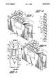
- FIG. 1is an isometric view of a circuit breaker with the handle block of this invention shown spaced therefrom in position to be installed to the circuit breaker in one selected orientation;
- FIG. 2is a view similar to FIG. 1, but showing the handle block rotated 180 degrees about a vertically extending axis to be installed to the circuit breaker in another selected orientation opposite that depicted in FIG. 1;
- FIG. 3is a plan view of the escutcheon rib and handle of the circuit breaker of FIGS. 1 and 2 showing the handle block of this invention installed thereto in one of two possible orientations;
- FIG. 4is a cross sectional view of the escutcheon rib, handle and handle block taken along the line 4--4 in FIG. 3.
- FIGS. 1 and 2 of the drawingshow a circuit breaker 2 in isometric views.
- Circuit breaker 2is a molded case circuit breaker such as the Cutler-Hammer® single pole FS or FH circuit breaker manufactured and sold by the assignee of this invention.
- the circuit breaker 2comprises a molded insulating housing 4 having a top wall 6 which contains an opening 8 for a toggle lever operating handle 10 pivotally mounted within the breaker housing.
- the reference to top wall 6is for purposes of this description and the orientation in the drawing only inasmuch as wall 6 is a front wall of the circuit breaker in its customary application when mounted in an electrical panelboard or other electrical apparatus.
- Opening 8is made to closely conform to the shape of operating handle 10 to provide a good seal between the handle 10 and the housing 4 to prevent the entry of dirt or other foreign particles into the circuit breaker housing as well as to minimize the egress of any arcing or electrical arc gasses when the breaker operates to interrupt an overloaded circuit.
- Circuit breaker 2is provided with a pair of wiring terminals 12, one at each end but only one shown, for connecting the circuit breaker to a load and an electrical source. As viewed in the drawings, the left-hand end of the circuit breaker is designated the ON end and the right-hand end is designated the OFF end. When the handle 10 is moved to be closest to the ON end as shown in FIG.
- the breaker mechanism within the housing 4is in the ON condition whereby electrical contacts thereof are closed and a circuit is completed through the circuit breaker 2 between the two terminals 12.
- the breaker mechanismis in its OFF condition whereby the electrical contacts are opened and no circuit is completed through the circuit breaker.
- An escutcheon rib 14is molded integrally with housing 4 on the top wall 6 thereof to surround the handle 10 and opening 8, spaced from the opening 8.
- the escutcheon rib 14may project through an opening in a dead front cover for an electrical panelboard or similar cover for other electrical apparatus in final application of the circuit breaker, thereby exposing only the rib 14, handle 10 and portion of the top wall 6 within the escutcheon rib 14 to the user of the equipment.
- the handle block 16 of this inventionis a molded plastic U-shaped member having a base 18 with a pair of legs 20 and 22 extending parallel to each other from opposite ends of the base.
- Leg 20is provided with a pair of lateral projections 24 and 26 (seen best in FIG. 2), one being located at the base 18 and the other being located at the distal end of leg 20.
- Leg 22is provided with a single lateral projection 28 at the distal end of the leg.
- the distal end of leg 22is also provided with a tool engaging notch 30 in the upper surface thereof communicating with the lateral surface of the leg 22.
- Base 18has a projection 32 which extends parallel to the legs 20 and 22 for a short distance. The distal end of projection 32 extends upwardly in an angular plane substantially parallel to the near or proximal surface of operating handle 10 to abut the handle 10 when the handle block 16 is installed to the circuit breaker 2.
- the inwardly or mutually facing surfaces of escutcheon rib 14 at the sides of opening 8are provided with opposed pairs of laterally aligned recesses 36 and 38.
- the handle block 16is installed to the circuit breaker 2 by moving the handle to the desired position, such as the ON position in FIG. 1, orienting the handle block 16 such that the base 18 is disposed on the OFF side of the handle 10 and the legs 20 and 22 extend toward the ON end of the circuit breaker. When so oriented, leg 20 is angled downward to permit projections 24 and 26 to engage in the recesses 38 and 36, respectively, at one side of the opening 8. The handle block 16 is then swung downward such that the leg 22 is brought into proximity of the rib 14 at the opposite side of the opening 8.
- legs 20 and 22are marginally less than the distance between opposed inner surfaces of raised rib 14 whereby lateral projection 28 on leg 22 prevents the handle block 16 from moving fully into the area within the raised escutcheon rib 14.
- inward pressure on the distal end of leg 22will defect that leg inwardly sufficient to align the projection 28 with the inner surface of rib 6 to allow the leg 22 to be moved downward against the surface of top wall 6.
- Lateral projection 28aligns with the recess 36, and release of leg 22 causes it to flex back to its initial condition whereby the lateral projection 28 engages the recess 36 to hold the handle block 16 firmly in position within the escutcheon rib 14.
- the circuit breaker mechanismis a trip-free mechanism and the positioning of handle block 16 in this manner does not prevent the circuit breaker from tripping on the occurrence of an overload. However, it is necessary to remove the handle block 16 to permit the handle 10 to move to its trip indicating position.
- notch 30cooperates with the inner lateral face of rib 14 to form a slot that is closed on three sides. Insertion of a flat bladed tool such as a screwdriver into the slot 30 and twisting thereon deflects the leg 22 inwardly to permit the single lateral projection 28 to move free of the appropriate recess 36 or 38 to thereby permit the handle block 16 to be removed.
- the handlemay be blocked in the OFF position merely by reversing the orientation of the handle block 16 and moving the handle 10 to the OFF position.
- the lateral projections 24 and 26engage recesses 36 and 38, respectively, in the left-hand inner surface of rib 14 as seen in FIG. 3 and the single lateral projection 28 engages the opposed recess 38 in the right-hand inner surface of the raised rib portion 14.
- the molded plastic handle block 16 of this inventionis readily and economically made. It's generally planar overall shape renders it easy to store in a workman's tool box, pockets or the like, and therefore very likely available when needed.
- the handle block 16is easy to install or remove, yet rigidly maintains its position when an attempt is made to move the handle 10 against the handle block. While the handle block of this invention is shown and described in the best mode contemplated for carrying out this invention, it is to be understood that it is susceptible of various modifications and changes without departing from the scope of the appended claims.
Landscapes
- Breakers (AREA)
Abstract
Description
Claims (16)
Priority Applications (1)
| Application Number | Priority Date | Filing Date | Title |
|---|---|---|---|
| US08/047,669US5290979A (en) | 1993-04-19 | 1993-04-19 | Handle block for electrical switching device |
Applications Claiming Priority (1)
| Application Number | Priority Date | Filing Date | Title |
|---|---|---|---|
| US08/047,669US5290979A (en) | 1993-04-19 | 1993-04-19 | Handle block for electrical switching device |
Publications (1)
| Publication Number | Publication Date |
|---|---|
| US5290979Atrue US5290979A (en) | 1994-03-01 |
Family
ID=21950286
Family Applications (1)
| Application Number | Title | Priority Date | Filing Date |
|---|---|---|---|
| US08/047,669Expired - Fee RelatedUS5290979A (en) | 1993-04-19 | 1993-04-19 | Handle block for electrical switching device |
Country Status (1)
| Country | Link |
|---|---|
| US (1) | US5290979A (en) |
Cited By (16)
| Publication number | Priority date | Publication date | Assignee | Title |
|---|---|---|---|---|
| US5349145A (en)* | 1993-08-02 | 1994-09-20 | General Electric Company | Circuit breaker operating handle interlock |
| US5905236A (en)* | 1997-06-25 | 1999-05-18 | Siemens Energy & Automation, Inc. | Circuit breaker movable actuator blocking and securing apparatus, means and system |
| US5907140A (en)* | 1997-09-29 | 1999-05-25 | Eaton Corporation | Circuit breaker having a snap-in attachable collar |
| US6528744B2 (en) | 2000-06-16 | 2003-03-04 | Deere & Company | Cover for vehicle control switch |
| US20040159530A1 (en)* | 2001-03-21 | 2004-08-19 | Benda Steven J. | Circuit breaker lock-out assembly |
| US20050237230A1 (en)* | 2002-09-05 | 2005-10-27 | Somfy Sas | Method of disabling the keyboard keys of a command-emitting device |
| US7137178B1 (en)* | 2005-09-13 | 2006-11-21 | Honda Motor Co., Ltd. | Protective device for vehicle seat belt latch release |
| US20060264870A1 (en)* | 2005-05-23 | 2006-11-23 | Carstens Jerry E | System comprising thong-shaped holder and absorbent article |
| US20080067043A1 (en)* | 2006-09-18 | 2008-03-20 | Master Lock Company Llc | Switch lockout device |
| US20100005922A1 (en)* | 2008-07-14 | 2010-01-14 | Siemens Energy & Automation, Inc. | Positive Handle Stop for Switches |
| USD645415S1 (en)* | 2009-09-18 | 2011-09-20 | Panasonic Corporation | Operation switch |
| GB2489242A (en)* | 2011-03-21 | 2012-09-26 | Cooper Medc Ltd | Switch locking assembly |
| US8330584B1 (en) | 2009-07-16 | 2012-12-11 | John Pfanstiehl | Remote control with lockable keys |
| US20150255229A1 (en)* | 2014-03-06 | 2015-09-10 | Yamaha Corporation | Switch Device with Erroneous Operation Preventer and the Erroneous Operation Preventer |
| US9208964B2 (en) | 2012-12-14 | 2015-12-08 | Master Lock Company Llc | Lockout device |
| US9859074B1 (en) | 2017-09-03 | 2018-01-02 | Carlos M. Martinez | Locking device for rocker switch |
Citations (10)
| Publication number | Priority date | Publication date | Assignee | Title |
|---|---|---|---|---|
| US2832857A (en)* | 1954-03-15 | 1958-04-29 | Wadsworth Electric Mfg Co | Locking plate for circuit breakers, switches and the like |
| US3109899A (en)* | 1960-10-18 | 1963-11-05 | Cutler Hammer Inc | Handle lock |
| US3629529A (en)* | 1970-02-25 | 1971-12-21 | Square D Co | Retaining means for operating handle of molded-case electric circuit breaker |
| US3678236A (en)* | 1971-04-23 | 1972-07-18 | Hugh S Hughes | Switch holder and guard |
| US4158116A (en)* | 1977-10-25 | 1979-06-12 | Gould Inc. | Snap-on handle blocking device |
| SU672662A1 (en)* | 1977-12-12 | 1979-07-05 | Предприятие П/Я В-8791 | Device for fixing tumbler switch lever |
| US4300030A (en)* | 1979-12-17 | 1981-11-10 | Gould Inc. | Handle blocking means for circuit breaker |
| US4791525A (en)* | 1987-11-02 | 1988-12-13 | Eaton Corporation | Circuit breaker with retainer for filler plate |
| US4820887A (en)* | 1988-05-02 | 1989-04-11 | Honeywell Inc. | Membrane keyboard blockout apparatus |
| US4882456A (en)* | 1985-11-04 | 1989-11-21 | Cooper Industries, Inc. | Locking device for electrical switch or circuit breaker handle |
- 1993
- 1993-04-19USUS08/047,669patent/US5290979A/ennot_activeExpired - Fee Related
Patent Citations (10)
| Publication number | Priority date | Publication date | Assignee | Title |
|---|---|---|---|---|
| US2832857A (en)* | 1954-03-15 | 1958-04-29 | Wadsworth Electric Mfg Co | Locking plate for circuit breakers, switches and the like |
| US3109899A (en)* | 1960-10-18 | 1963-11-05 | Cutler Hammer Inc | Handle lock |
| US3629529A (en)* | 1970-02-25 | 1971-12-21 | Square D Co | Retaining means for operating handle of molded-case electric circuit breaker |
| US3678236A (en)* | 1971-04-23 | 1972-07-18 | Hugh S Hughes | Switch holder and guard |
| US4158116A (en)* | 1977-10-25 | 1979-06-12 | Gould Inc. | Snap-on handle blocking device |
| SU672662A1 (en)* | 1977-12-12 | 1979-07-05 | Предприятие П/Я В-8791 | Device for fixing tumbler switch lever |
| US4300030A (en)* | 1979-12-17 | 1981-11-10 | Gould Inc. | Handle blocking means for circuit breaker |
| US4882456A (en)* | 1985-11-04 | 1989-11-21 | Cooper Industries, Inc. | Locking device for electrical switch or circuit breaker handle |
| US4791525A (en)* | 1987-11-02 | 1988-12-13 | Eaton Corporation | Circuit breaker with retainer for filler plate |
| US4820887A (en)* | 1988-05-02 | 1989-04-11 | Honeywell Inc. | Membrane keyboard blockout apparatus |
Cited By (26)
| Publication number | Priority date | Publication date | Assignee | Title |
|---|---|---|---|---|
| US5349145A (en)* | 1993-08-02 | 1994-09-20 | General Electric Company | Circuit breaker operating handle interlock |
| US5905236A (en)* | 1997-06-25 | 1999-05-18 | Siemens Energy & Automation, Inc. | Circuit breaker movable actuator blocking and securing apparatus, means and system |
| US5907140A (en)* | 1997-09-29 | 1999-05-25 | Eaton Corporation | Circuit breaker having a snap-in attachable collar |
| US6528744B2 (en) | 2000-06-16 | 2003-03-04 | Deere & Company | Cover for vehicle control switch |
| US20040159530A1 (en)* | 2001-03-21 | 2004-08-19 | Benda Steven J. | Circuit breaker lock-out assembly |
| US6844512B2 (en)* | 2001-03-21 | 2005-01-18 | Brady Worldwide, Inc. | Circuit breaker lock-out assembly |
| US20050237230A1 (en)* | 2002-09-05 | 2005-10-27 | Somfy Sas | Method of disabling the keyboard keys of a command-emitting device |
| US7256726B2 (en) | 2002-09-05 | 2007-08-14 | Somfy Sas | Method of disabling the keyboard keys of a command-emitting device |
| US20060264870A1 (en)* | 2005-05-23 | 2006-11-23 | Carstens Jerry E | System comprising thong-shaped holder and absorbent article |
| US7137178B1 (en)* | 2005-09-13 | 2006-11-21 | Honda Motor Co., Ltd. | Protective device for vehicle seat belt latch release |
| US7501593B2 (en)* | 2006-09-18 | 2009-03-10 | Master Lock Company Llc | Switch lockout device |
| US7977590B2 (en) | 2006-09-18 | 2011-07-12 | Master Lock Company Llc | Switch lockout device |
| US20080067043A1 (en)* | 2006-09-18 | 2008-03-20 | Master Lock Company Llc | Switch lockout device |
| US20090205934A1 (en)* | 2006-09-18 | 2009-08-20 | Master Lock Company Llc | Switch lockout device |
| WO2008036602A3 (en)* | 2006-09-18 | 2008-12-18 | Master Lock Co | Switch lockout device |
| US8132483B2 (en)* | 2008-07-14 | 2012-03-13 | Siemens Industry, Inc. | Positive handle stop for switches |
| US20100005922A1 (en)* | 2008-07-14 | 2010-01-14 | Siemens Energy & Automation, Inc. | Positive Handle Stop for Switches |
| US8330584B1 (en) | 2009-07-16 | 2012-12-11 | John Pfanstiehl | Remote control with lockable keys |
| USD645415S1 (en)* | 2009-09-18 | 2011-09-20 | Panasonic Corporation | Operation switch |
| GB2489242A (en)* | 2011-03-21 | 2012-09-26 | Cooper Medc Ltd | Switch locking assembly |
| US20140001015A1 (en)* | 2011-03-21 | 2014-01-02 | Cooper Medc Limited | Locking switch assembly and manufacture of locking component |
| GB2489242B (en)* | 2011-03-21 | 2016-02-03 | Cooper Technologies Co | Locking switch assembly and manufacture of locking component |
| US9208964B2 (en) | 2012-12-14 | 2015-12-08 | Master Lock Company Llc | Lockout device |
| US20150255229A1 (en)* | 2014-03-06 | 2015-09-10 | Yamaha Corporation | Switch Device with Erroneous Operation Preventer and the Erroneous Operation Preventer |
| US9466440B2 (en)* | 2014-03-06 | 2016-10-11 | Yamaha Corporation | Switch device with erroneous operation preventer and the erroneous operation preventer |
| US9859074B1 (en) | 2017-09-03 | 2018-01-02 | Carlos M. Martinez | Locking device for rocker switch |
Similar Documents
| Publication | Publication Date | Title |
|---|---|---|
| US5290979A (en) | Handle block for electrical switching device | |
| AU766594B2 (en) | Circuit interrupter with improved din rail mounting adaptor | |
| CA2566649C (en) | Electrical switching apparatus operating mechanism with operating member therefor, and enclosure assembly employing the same | |
| EP0204479B1 (en) | Operating handle locking device for circuit interrupters | |
| CA1329404C (en) | Circuit breaker auxiliary device snap-on package and method of making same | |
| US4631376A (en) | Molded case circuit breaker with an improved arc gas external venting system | |
| CA2039033C (en) | Adapter providing unitary mounting capability for standard circuit breaker | |
| KR100964260B1 (en) | Circuit breaker | |
| US5109142A (en) | Circuit breaker handle tie for automated assembly | |
| US5060107A (en) | Molded case circuit breaker operating handle guard | |
| US6423913B1 (en) | Locking device for handle operating mechanisms | |
| GB2285886A (en) | Circuit breaker | |
| CA1206189A (en) | Switch fuse unit | |
| US6137068A (en) | Combined handle-guard and grip for plug-in circuit breakers | |
| US6437262B1 (en) | Handle operating assembly for an electric disconnect switch | |
| EP3594986B1 (en) | Switching mechanism of circuit breaker | |
| JPH04212227A (en) | Arc chute structure of current-limit type breaker | |
| MXPA02010306A (en) | Finger barrier for electric power switches and electric power switch incorporating the same. | |
| US7019240B2 (en) | Electrical switching apparatus interface assembly and operating handle attachment therefor | |
| US6437671B1 (en) | Circuit interrupter with secure base and terminal connection | |
| AU763283B2 (en) | Circuit interrupter with accessory trip interface and break-away access thereto | |
| CA2619705A1 (en) | Electrical switching device | |
| US4158116A (en) | Snap-on handle blocking device | |
| CA2103312C (en) | Protective cover for electrical terminals and method of using same | |
| US6806800B1 (en) | Assembly for mounting a motor operator on a circuit breaker |
Legal Events
| Date | Code | Title | Description |
|---|---|---|---|
| FEPP | Fee payment procedure | Free format text:PAYOR NUMBER ASSIGNED (ORIGINAL EVENT CODE: ASPN); ENTITY STATUS OF PATENT OWNER: LARGE ENTITY | |
| AS | Assignment | Owner name:EATON CORPORATION, OHIO Free format text:ASSIGNMENT OF ASSIGNORS INTEREST;ASSIGNOR:GRASS, WILLIAM E.;REEL/FRAME:006526/0779 Effective date:19930415 | |
| AS | Assignment | Owner name:THOMAS & BETTS CORPORATION, A NJ CORP., TENNESSEE Free format text:ASSIGNMENT OF ASSIGNORS INTEREST;ASSIGNOR:EATON CORPORATION, AN OH CORP.;REEL/FRAME:007011/0942 Effective date:19940131 | |
| REMI | Maintenance fee reminder mailed | ||
| FPAY | Fee payment | Year of fee payment:4 | |
| SULP | Surcharge for late payment | ||
| FEPP | Fee payment procedure | Free format text:PAYOR NUMBER ASSIGNED (ORIGINAL EVENT CODE: ASPN); ENTITY STATUS OF PATENT OWNER: LARGE ENTITY Free format text:PAYER NUMBER DE-ASSIGNED (ORIGINAL EVENT CODE: RMPN); ENTITY STATUS OF PATENT OWNER: LARGE ENTITY | |
| FPAY | Fee payment | Year of fee payment:8 | |
| AS | Assignment | Owner name:THOMAS & BETTS INTERNATIONAL, INC., NEVADA Free format text:ASSIGNMENT OF ASSIGNORS INTEREST;ASSIGNOR:THOMAS & BETTS CORPORATION;REEL/FRAME:012785/0923 Effective date:20020325 | |
| AS | Assignment | Owner name:CONNECTICUT ELECTRIC & SWITCH MFG. CO., WASHINGTON Free format text:ASSIGNMENT OF ASSIGNORS INTEREST;ASSIGNOR:THOMAS & BETTS INTERNATIONAL, INC.;REEL/FRAME:016038/0142 Effective date:20041130 | |
| REMI | Maintenance fee reminder mailed | ||
| LAPS | Lapse for failure to pay maintenance fees | ||
| STCH | Information on status: patent discontinuation | Free format text:PATENT EXPIRED DUE TO NONPAYMENT OF MAINTENANCE FEES UNDER 37 CFR 1.362 | |
| FP | Lapsed due to failure to pay maintenance fee | Effective date:20060301 | |
| AS | Assignment | Owner name:CONNECTICUT ELECTRIC, INC., MISSOURI Free format text:ASSIGNMENT OF ASSIGNORS INTEREST;ASSIGNORS:PARALLAX POWER SUPPLY, LLC;CONNECTICUT ELECTRIC & SWITCH MFG. CO.;REEL/FRAME:019617/0105 Effective date:20070112 |