US5290294A - Method and apparatus for removal of a foreign body cavity - Google Patents
Method and apparatus for removal of a foreign body cavityDownload PDFInfo
- Publication number
- US5290294A US5290294AUS07/839,011US83901192AUS5290294AUS 5290294 AUS5290294 AUS 5290294AUS 83901192 AUS83901192 AUS 83901192AUS 5290294 AUS5290294 AUS 5290294A
- Authority
- US
- United States
- Prior art keywords
- sheath
- tool
- foreign body
- snaring
- obturator
- Prior art date
- Legal status (The legal status is an assumption and is not a legal conclusion. Google has not performed a legal analysis and makes no representation as to the accuracy of the status listed.)
- Expired - Lifetime
Links
- 0C1[C@]2C1CC*C2Chemical compoundC1[C@]2C1CC*C20.000description1
Images


Classifications
- A—HUMAN NECESSITIES
- A61—MEDICAL OR VETERINARY SCIENCE; HYGIENE
- A61B—DIAGNOSIS; SURGERY; IDENTIFICATION
- A61B17/00—Surgical instruments, devices or methods
- A61B17/28—Surgical forceps
- A61B17/29—Forceps for use in minimally invasive surgery
- A—HUMAN NECESSITIES
- A61—MEDICAL OR VETERINARY SCIENCE; HYGIENE
- A61B—DIAGNOSIS; SURGERY; IDENTIFICATION
- A61B1/00—Instruments for performing medical examinations of the interior of cavities or tubes of the body by visual or photographical inspection, e.g. endoscopes; Illuminating arrangements therefor
- A61B1/307—Instruments for performing medical examinations of the interior of cavities or tubes of the body by visual or photographical inspection, e.g. endoscopes; Illuminating arrangements therefor for the urinary organs, e.g. urethroscopes, cystoscopes
- A—HUMAN NECESSITIES
- A61—MEDICAL OR VETERINARY SCIENCE; HYGIENE
- A61B—DIAGNOSIS; SURGERY; IDENTIFICATION
- A61B17/00—Surgical instruments, devices or methods
- A61B17/22—Implements for squeezing-off ulcers or the like on inner organs of the body; Implements for scraping-out cavities of body organs, e.g. bones; for invasive removal or destruction of calculus using mechanical vibrations; for removing obstructions in blood vessels, not otherwise provided for
- A61B17/221—Gripping devices in the form of loops or baskets for gripping calculi or similar types of obstructions
- A61B2017/2212—Gripping devices in the form of loops or baskets for gripping calculi or similar types of obstructions having a closed distal end, e.g. a loop
- A—HUMAN NECESSITIES
- A61—MEDICAL OR VETERINARY SCIENCE; HYGIENE
- A61B—DIAGNOSIS; SURGERY; IDENTIFICATION
- A61B17/00—Surgical instruments, devices or methods
- A61B17/28—Surgical forceps
- A61B17/29—Forceps for use in minimally invasive surgery
- A61B2017/2926—Details of heads or jaws
- A61B2017/2931—Details of heads or jaws with releasable head
- A—HUMAN NECESSITIES
- A61—MEDICAL OR VETERINARY SCIENCE; HYGIENE
- A61B—DIAGNOSIS; SURGERY; IDENTIFICATION
- A61B2217/00—General characteristics of surgical instruments
- A61B2217/002—Auxiliary appliance
- A61B2217/007—Auxiliary appliance with irrigation system
- A—HUMAN NECESSITIES
- A61—MEDICAL OR VETERINARY SCIENCE; HYGIENE
- A61F—FILTERS IMPLANTABLE INTO BLOOD VESSELS; PROSTHESES; DEVICES PROVIDING PATENCY TO, OR PREVENTING COLLAPSING OF, TUBULAR STRUCTURES OF THE BODY, e.g. STENTS; ORTHOPAEDIC, NURSING OR CONTRACEPTIVE DEVICES; FOMENTATION; TREATMENT OR PROTECTION OF EYES OR EARS; BANDAGES, DRESSINGS OR ABSORBENT PADS; FIRST-AID KITS
- A61F2/00—Filters implantable into blood vessels; Prostheses, i.e. artificial substitutes or replacements for parts of the body; Appliances for connecting them with the body; Devices providing patency to, or preventing collapsing of, tubular structures of the body, e.g. stents
- A61F2/82—Devices providing patency to, or preventing collapsing of, tubular structures of the body, e.g. stents
- A—HUMAN NECESSITIES
- A61—MEDICAL OR VETERINARY SCIENCE; HYGIENE
- A61M—DEVICES FOR INTRODUCING MEDIA INTO, OR ONTO, THE BODY; DEVICES FOR TRANSDUCING BODY MEDIA OR FOR TAKING MEDIA FROM THE BODY; DEVICES FOR PRODUCING OR ENDING SLEEP OR STUPOR
- A61M3/00—Medical syringes, e.g. enemata; Irrigators
- A61M3/02—Enemata; Irrigators
- A61M3/0279—Cannula; Nozzles; Tips; their connection means
Definitions
- the present inventionrelates generally to the field of instruments for insertion into a body cavity. More specifically, the present invention relates to instruments which are used to remove foreign bodies from the urethra and bladder.
- the prostateis a walnut-sized gland that extends around the urethral lumen from the neck of the bladder to the pelvic floor. Because of the close relationship of the prostate to the urethra, enlargement of the prostate, usually referred to as hyperplasia or hypertrophy, may fairly quickly obstruct the urethra, particularly if the hyperplasia occurs close to the lumen. Such an obstruction inhibits normal micturition, which causes an accumulation of urine in the bladder.
- tubular stents associated with the aforementioned methodare generally designed to remain in place indefinitely. However, removal of the stent may occasionally be required. For example, the stent may have been placed poorly, or it may have drifted out of its appropriate location. Removal of the stent may also be required if complications, such as infection, bleeding or urethral stricture, develop.
- a procedure for entering the prostatic environment through the natural opening of the urethrawould avoid the need for making an incision into the patient. It is important that such a procedure minimize trauma to the soft tissues of the urethral lining. Additionally, a means for easily locating both the object to be removed and the removal instrument would preferably be provided to minimize the time and difficulty of the procedure. Moreover, it would be desireable to have a plurality of techniques available which can be successively attempted without delay, in the event one technique was unsuccessful. The availability of a plurality of techniques would allow surgery to be used only as a last resort.
- One prior art method used for the removal of foreign bodies and pieces of tissue from the urethra, bladder or other body cavitycomprises transurethrally inserting a forceps through a cystoscope-urethroscope sheath, grasping the foreign body with the forceps under the vision of a transurethral telescope, and pulling the foreign body through the sheath.
- Such forceps, sheaths and telescopesare available, for example, from Karl Storz Endoscopy-America, Inc., Culver City, Calif.
- the foreign bodymay require substantial crushing and/or breaking in order to fit through the sheath when this prior art method is practiced.
- stone basketsare comprised of two or more flexible wires forming a "basket" into which the stone or other foreign body may be trapped. The baskets are then pulled into a transurethral sheath which is then removed.
- stone basketsare not capable of crushing kidney stones or other foreign bodies trapped by the basket. Removal of larger objects requires the use of a forceps or other tool prior to use of the stone basket to break up and/or crush any objects which will not fit through the sheath. Breaking the object into pieces, also, necessitates the removal of many pieces, taking additional time. Moreover, it may be difficult to ascertain that all of the pieces have been removed. Thus, there is a need for a more rapid and effective means for removal of foreign bodies from the urethra and/or bladder.
- Cutting loopshave been used in the surgical treatment of hyperplasia of the prostate and other urological conditions. These sharp, rigid prior art loops have been adapted to fit through a transurethral sheath in a nonsecured fashion. The cutting loops have been used for cutting undesired tissue, however, such loops have never been adapted for the removal of foreign objects.
- the present inventionprovides an apparatus of novel design for use in the rapid, non-surgical removal of foreign bodies from the urethra and bladder.
- a transurethral snaring toolfor encircling, and thereby ensnaring, a foreign body within the urethral lumen or bladder.
- the snaring toolhas an encircling means, such as a loop, to encircle the foreign body.
- the transurethral toolis further provided in one embodiment with an introduction sheath, suitable for housing a cystoscopic rod lens or other telescope device or viewing means, and an obturator, for the atraumatic introduction of the sheath.
- the transurethral toolis provided with a means for controllably retracting the foreign body, which will pull the foreign body into the sheath.
- a jack screwis provided as such a means of controllable retraction.
- the jack screwprovides significant mechanical advantage, thereby allowing a user of the invention to retract the foreign body without expenditure of great force.
- the obturatoris, preferably, removed from the sheath prior to insertion of the snaring tool.
- the snaring toolis, preferably, adapted to receive a rod lens or other telescope device for viewing of the loop within the urethra and/or bladder.
- a pistol grip with a trigger ratchet assemblyis used to controllably retract the snaring tool.
- the trigger ratchet assemblyfunctions similar to a device commonly used in caulking guns, so that each pull of the trigger further advances the ratchet to retract the snaring tool.
- a foreign body removal apparatushaving additional tools to insert through the transurethral sheath.
- One such toolis a rigid forward forceps. This tool is useful for manipulating a foreign body within the urethra and/or bladder so that it may be removed by another tool, or may also be used to grab the foreign body and pull it through the sheath.
- Another tool in this embodiment of the inventionis a lateral forceps which grabs from the side. The lateral forceps has been found particularly useful in shaping foreign bodies into a shape which can be easily removed by the other removal tools.
- a non-surgical method for removal of a foreign body from the urethra and/or bladdercomprising the steps of inserting an atraumatic sheath into the urethra, pushing the foreign body into the bladder, inserting a snaring tool of the present invention through the sheath, snaring the foreign body to be removed, and controllably retracting the object inside the sheath. The sheath may then be removed from the urethra.
- the removal tools and procedures of the present inventionenjoy several significant advantages.
- the use of the present inventionsignificantly reduces the complications from removal of a foreign object from the urethra or bladder due to the avoidance of surgery in nearly all cases.
- the provision of several removal tools and procedures which may be used without making an incision into the patientgives the user of the present invention several options before resorting to surgery.
- the various tools of the present inventionwill each fit through a single transurethral sheath which may be left in place during the changing of tools. Thus, the tools may be easily exchanged in a short period of time. All of the tools may be sterilized prior to use in a conventional manner.
- the obturator provided by the present inventionmakes a smooth connection with the transurethral sheath.
- the sheath and obturator tipare constructed of durable, solid, corrosion resistant material.
- the materialis biologically inactive and compatible with the lining of the urethra.
- the obturator tiphas irrigation ports which allow for irrigation which further reduces trauma during insertion of the sheath.
- the sheathbeing constructed of durable material allows for the foreign body to be crushed as the stent is pulled into the sheath without damaging the sheath. Thus, the foreign body is crushed to a size that will fit through the sheath during retraction of the snaring tool.
- An additional advantage of the obturator tipis that it provides for a lens of the telescope device to be inserted through the center of the obturator to form a continuous smooth tip.
- the sheathmay be atraumatically introduced with continuous viewing of the area ahead of the sheath. This viewing is particularly advantageous because it allows the user of the invention to locate a foreign object found in the urethra for pushing it into the bladder using the obturator tip.
- By pushing the object into the bladderthe object is placed in a larger space where it may be manipulated without causing trauma to surrounding tissue.
- the irrigation fluid coming through the obturator tipallows a clear view of the surrounding anatomy.
- the loop of the snaring toolis preferably flexible and constructed of metal wire.
- the loopcould be constructed of coated wire, a polymer material, filament, or multi-filament.
- the loophas a circumference slightly larger than the object to be removed.
- the loopis well adapted for snaring a foreign object without tearing or cutting the object.
- the tip of the snaring tool containing the loopis removable for easy replacement, yet the tip will not come apart during use of the tool.
- the snaring toollike the other removal tools, is sufficiently strong to retain the foreign object as the object is pulled and crushed into the sheath.
- the snaring tool tipis sufficiently economical in terms of material and manufacturing costs so that it is disposed of after use, thus avoiding the possibility that the loop in the tip will deform or break due to overuse.
- the jack screwwhich is preferably provided to slowly and controllably retract the snaring tool thereby crushing the foreign body as it is pulled into the sheath, additionally controls the movement of the telescope device during use of the snaring tool.
- Thisprovides the additional advantage that the telescope lens or other visualization means remains aligned with the tip of the removal tool as it is being retracted. Thus, the field of view remains on the foreign object being removed.
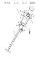
- FIG. 1is a perspective view of an apparatus for removal of a foreign body from the urethra or bladder in accordance with one embodiment of the present invention, showing a telescope in phantom.
- FIG. 2is a perspective view of the sheath.
- FIG. 3is a perspective view of the snaring tool, showing the removable loop tip thereof and the jack screw for controllably retracting the snaring tool inside the sheath.
- FIG. 3ais a perspective view of the removable tip of the snaring tool showing the tip in place with the collar secured with tension from the spring.
- FIG. 3bis a perspective view of the removable tip of the snaring tool shown with the collar retracted so as to allow the removal of the removable tip.
- FIG. 4is a perspective view of the obturator.
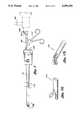
- FIG. 5is a plan view of another embodiment of the present invention showing a forward forceps tool and a telescope, in phantom, extending through the sheath with a locking bridge attached to the sheath.
- FIG. 5ais a blow-up view in perspective of the tip of a forward forceps tool.
- FIG. 5bis a blow-up view in perspective of the tip of a lateral forceps tool.
- FIGS. 6a through 6erepresent a schematic presentation of the operation of the snaring tool in accordance with a preferred method of the present invention, showing the tip of the snaring tool extending through the tip of the sheath and snaring a tubular stent which is pulled into the sheath.
- FIG. 1an apparatus for removal of a foreign object from a body cavity embodying the present invention in a preferred form.
- proximalwill be used to refer to the end of the apparatus closest to an operator when the apparatus is in use
- distalwill be used to refer to the end further from an operator.
- the apparatusas shown in FIG. 1, has two elements, a sheath 12 and a snaring tool 18.
- the sheath 12is a substantially rigid tube forming an axially elongate hollow shaft throughout most of its length.
- the sheathis constructed of corrosion resistant, durable, hard metal without any plating in order to maintain a smooth surface for the atraumatic introduction of the sheath into the soft tissue of the urethral lining.
- the materialis biologically inactive and compatible with the lining of the urethra.
- Other materials, such as rigid biocompatible plasticsmay also be used.
- the sheath 12is removably locked to the snaring tool 18 or other elements of the present invention by a pair of grooves 22, cut into a cylindrical housing 20, on opposite sides thereof.
- the cylindrical housing 20is disposed near the top of the sheath 12 so as to allow the elements attached to the sheath 12 to fit through the axially elongate hollow shaft of the sheath 12.
- the other elements to be locked to the sheathmay incorporate a pair of C-clips 24 disposed on opposite sides for locking to the grooves 22. By sliding the C-clips 24 through the grooves 22, the elements are locked together. While the embodiment shown uses a lock of C-clips 24 and grooves 22, a variety of other well known locking means are suitable for attaching the various elements of the present invention to the sheath 12. For example, any standard bayonet mount would prove suitable.
- a cock valve 30 having an irrigation drainage port 28is situated on one side of the cylindrical housing 20 of the sheath 12.
- the cock valve 30allows backflowing fluids to escape the sheath 12 when positioned in the "on" position, and to prohibit the release of such fluids when in the "off” position.
- an irrigation input port 32is situated opposite the drainage port 28 on the cylindrical housing 20.
- the portscomprise components of the irrigation system of the present invention which is described below.
- the snaring tool 18 of this embodimentcomprises two component sections which move independently of each other.
- the non-elevating component 38comprises an attaching means 40 with an integral jack screw key 42.
- the jack screw key 42rotates freely around the attaching means 40.
- a jack screw handle 46advantageously, enables the jack screw key 46 to be turned freely by an operator.
- the other component of the snaring toolis the elevating component 50.
- the elevating component 50comprises a narrow axially elongate shaft 52 with an encircling means, such as a loop 54, secured to its distal end.
- the loop 54is preferably flexible and constructed of wire. Alternatively, the loop 54 could be constructed of coated wire, a polymer material, filament, or multifilament.
- the loop 54may be immediately adjacent to the distal end of the shaft 52 as shown, or the loop 54 may be formed slightly away from the distal end of the shaft 52 to provide additional flexibility (not shown).
- the attachment of the loop 54 to the shaft 52may, advantageously, be a wire unitary with the loop 54; alternatively, the attachment may be a separate piece of material.
- the loop 54may be coplanar with the shaft 52, or preferably, the loop 54 comes out of the plane of the shaft 52. In a particularly preferred embodiment, the loop 54 is perpendicular to the axis of the shaft 52.
- the proximal end of the shaft 52is attached to a jack screw 58 which is threaded through the jack screw key 42.
- a jack screw 58which is threaded through the jack screw key 42.
- the elevating component 50including the loop 54 and any foreign body held by the loop 54 do not rotate as the elevating component 50 rises relative to the non-elevating component 38.
- an operator of the embodiment of the apparatus shownwill be able to extend or retract the loop 54 relative to the sheath 12 by turning the jack screw key 42.
- the jack screw 58must be secure enough to pull a foreign body snared by the loop 54 into the sheath 12 along with the loop 54 when the loop 54 is retracted.
- a jack system operating through gears and a row of stepsmay be provided (not shown).
- a pistol grip with a trigger ratchet assemblymay be used to controllably retract the snaring tool 18.
- the trigger ratchet assembly of this alternative embodimentmay function similar to a device commonly used in caulking guns, so that each pull of the trigger further advances the ratchet to retract the snaring tool 18.
- the loop 54 of the snaring tool 18is flexible and has a circumference slightly larger than the object to be removed.
- the loop 54is well adapted for snaring a foreign object without tearing or cutting the object.
- the loop 54is removable for easy replacement, yet the tip will not come apart during use of the tool.
- the loop 54like the grasping component of the other removal tools which are described herein, is sufficiently strong to retain the foreign object as the object is pulled and crushed into the sheath 12.
- the loop 54is sufficiently economical in terms of material and manufacturing costs so that it may be disposed after use. Disposing the used loop 54 avoids the need to resterilize the tip 54 after use and additionally avoids the possibility that the loop 54 will deform or break due to overuse. Therefore, the loop 54 is preferably detachable from the shaft 52 of the removal tool 18 for rapid replacement. Used loops are preferably disposed after a single use because the loop 54 may tend to deform after each use.
- FIGS. 3a and 3bshow one embodiment of a system for the rapid replacement of the loop 54.
- the loop 54is integral to the tip piece 72.
- the tip piece 72is held in place by a locking mechanism.
- the locking mechanismis a spring loaded collar 80, as seen in FIG. 3a.
- the tip piece 72incorporates a hook 74 at its proximal end which is adapted to fit into a similar hook 76 at the distal end of the shaft 52.
- a spring-loaded collar 80is pulled down in order to expose the hook 76 on the shaft.
- the collarsecurably holds the tip piece 72 on the snaring tool 18 during use.
- the collar 80is released, and the spring 82 keeps the collar 80 secured over the two hooks 74, 76, as best shown in FIG. 3b.
- a viewing means 60is provided to enable an operator to directly visualize the end of the removal tool 18 and the area around it while the tool is inside a body cavity (not shown).
- a telescope 60is provided as viewing means.
- a variety of telescopes which are useful as viewing means in this applicationare disclosed in U.S. Pat. No. 3,257,902, issued to Hopkins, and may be obtained from Karl Storz.
- the telescope 60is a rigid rod lens.
- the telescope 60 in the embodiment shownadvantageously extends through the sheath 12 to terminate at a viewing lens 62 just below where the loop 54 of the snaring tool 18 is attached.
- the telescope 60may, advantageously, be locked to the elevating component 50 of the snaring tool 18 so that the telescope 60 is retracted or extended concurrently with the loop 54.
- a locking port 66is provided at the proximal end of the removal tool 18 to secure the telescope 60.
- a variety of other suitable locksis available, such as a luer lock.
- a locking port handle 68is provided to enable an operator to easily turn the locking port 66 to secure the telescope 60.
- the jack screw key 42which is preferably provided to slowly and controllably crush the foreign object as it is pulled into the sheath 12, additionally controls the movement of the telescope device 60 during use of the snaring tool 18. This provides the additional advantage that the viewing lens 62 remains aligned with the tip of the removal tool 54 as it is being retracted. Thus, the user's field of view remains on the foreign object being removed.
- the irrigation systemprovides flushing of blood away from the lens of the telescope 60 to aid in the viewing of the tools and the foreign object to be removed.
- the irrigation input ports 32are adapted to continuously receive flushing fluid, for example from a hanging container of saline, through an irrigation conduit (not shown).
- the flushing fluidcan be supplied through the sheath 12 to flush blood away from the telescope viewing lens 62.
- the flushing fluidcan be supplied through a plurality of irrigation ports along the length of an integral sheath/obturator.
- irrigation fluidalso inhibits the coagulation of any blood within the urethra. If it is necessary to drain fluid during the use of the apparatus of the present invention, the drainage port 28 may be opened through the use of the cock valve 30.
- the irrigation conduitwill need to be removed prior to drainage of fluid from the port 28. Backflowing fluid will then drain, by gravity flow, and may be disposed of. Alternatively, continuous flow irrigation may be provided, whereby back-flowing fluid continuously drains through a conduit separate from the inflow irrigation conduit.
- An obturator 84is also provided for use with the present invention.
- the obturator 84is designed so as to avoid trauma during the insertion of the sheath 12 through the urethra. Once the transurethral sheath 12 is in place, the obturator 84 may be easily removed and replaced with a removal tool.
- the obturator 84may also be used to push foreign objects found in the urethra into the bladder. Pushing the object into the bladder is advantageous in that the object is put in a larger space, where the object can be manipulated without causing trauma to surrounding tissue.
- the obturatormay be integral with an atraumatic sheath or, preferably, may be a removable tool which can be attached to the sheath 12.
- the obturator 84is removed, leaving the sheath in place transurethrally to allow insertion of tools through the sheath 12.
- the obturatoris a substantially rigid, axially elongate shaft 86 with a diameter less than that of the inside of the sheath 12 throughout most of its length.
- the obturator 84has a tip 88 which is constructed of the same biocompatible material as the sheath 12.
- the tip 88 of the obturator, as shown,is, advantageously, a separate piece so that it may be replaced if damaged.
- a tip 88 which is integral with the obturator shaft 86may also be provided.
- the obturator tip 88makes a smooth connection with the end of the sheath 12 when it is inserted through the sheath 12 in accordance with the present invention.
- a cylindrical housing 90is provided.
- the housing 90may incorporate a pair of C-clips 24 disposed on opposite sides for locking the obturator 84 to grooves 22 on the sheath housing 20. While the embodiment shown uses a lock of C-clips 24 and grooves 22, a variety of other well-known locking means are suitable for attaching an obturator of the present invention to the sheath.
- a telescope 60 in the embodiment shownextends through the obturator 84 to terminate at the viewing lens 62 at the distal end of the obturator 84.
- the viewing lens 62is shaped to create an atraumatic continuous seam with the obturator tip 88.
- the sheathmay be atraumatically introduced with continuous viewing of the area ahead of the sheath. This viewing is particularly advantageous because it allow the user of the invention to locate a foreign object found in the urethra, and thus avoid the object.
- the viewingis also advantageous for pushing the object into the bladder using the obturator tip 88, in accordance with a preferred method of the present invention.
- the irrigation fluid flowing through the exit holes 94 in the obturator tip 88helps reduce trauma while the object is being pushed.
- the telescope 60may be locked to the obturator 84.
- a locking port 66is provided at the proximal end of the obturator 84 to secure the telescope 60.
- the locking port handle 68is provided to enable an operator to easily turn the locking port 66 to secure the telescope 60 to the obturator 84.
- the obturator housing 90in the embodiment shown, has an irrigation input port 32 situated on one side.
- a plurality of irrigation holes 94 through which irrigation fluid can exitare preferably located within the tip 88.
- irrigation slots(not shown) could be provided for the exit of irrigation fluid. Irrigation fluid flowing through the irrigation holes 94 will keep the light input free from blood and other debris to allow clear vision of the tip 88 as the obturator 84 is inserted through the urethra. Irrigation fluid flowing through the irrigation holes 94, advantageously, also serves to facilitate and reduce trauma during insertion of the obturator 84 through the urethra.
- additional toolsare provided for manipulating a foreign object within the urethra or bladder.
- the provision of these additional toolsallows additional non-surgical procedures to be performed in the event that removal with the snaring tool is not possible.
- An incision into the patientis, preferably, avoided in order to reduce the risk of complications associated with such surgery.
- the additional toolsare inserted through the sheath 12 after it is placed within the urethra.
- the sheath 12may be left in place as the various tools are exchanged.
- the toolsmay be easily exchanged in a short period of time.
- the toolsare preferably used with a viewing means to allow a view of the operation of the tools within the urethra or bladder.
- the viewing meansis a telescope 60 inserted through a locking bridge 98.
- the locking bridge 98facilitates control over the various components of this embodiment of the invention.
- the locking bridgehas a pair of C-clips 24 for locking to the sheath 12 as described above in connection with FIGS. 1 and 4.
- the locking bridge 98provides two channels through which components may be inserted.
- the first channel 102extends through the bridge element 104 of the locking bridge.
- the bridge element 104terminates with a conical structure 106 which is adapted to receive a telescope 60 in accordance with a preferred embodiment of the present invention.
- the conical structure 106is cut off on the inside part of the bridge in order to facilitate the insertion of a tool into the second channel 108.
- the bridge element 104provides stabilization for the component inserted through it. This is advantageous in the use of a viewing means in that the field of vision is stably maintained during use of the additional tools.
- the additional tool shown in FIG. 5is a forward forceps tool 110, illustrated in position after it has been inserted through the second channel 108 of the locking bridge 98 and through the sheath 12.
- a detail of the distal tip of this toolis shown in FIG. 5a.
- the size of the forcepsmay vary depending on the size of the object to be removed, however, the forceps must be capable of fitting through the sheath 12.
- the major portion of the tool, inserted through the sheath 12is an axially elongated shaft.
- the forward forceps 110is operated through a scissors-like mechanism 112 which extends parallel to the axially elongated shaft at the proximal end of the tool.
- the forward forceps tool 110has been found particularly useful in the removal of foreign bodies which cannot be easily removed with the snaring tool.
- the forward forceps tool 110may be used to pull a foreign object directly into the sheath 12, or it may be used to shape a foreign object for easier removal with another tool.
- the forward forceps tool 110may also be used to push a foreign object out of the urethra and into the bladder, or to hold a foreign object tightly against the loop 54 of the snaring tool 18 in order to facilitate removal of an object with the snaring tool 18.
- a lateral forceps tool 116is substantially identical to the forward forceps tool 110. However, the lateral forceps tool 116 has a scissor-like mechanism which extends perpendicular to an axially elongated shaft of the tool at the proximal end of the tool. Thus, the lateral forceps tool grabs from the side as illustrated in FIG. 5b where the tip of the lateral forceps tool 116 is shown.
- This lateral forceps tool 116may be used for any of the purposes the forward forceps tool 110 may be used, and additionally has been found useful in shaping a foreign object so that it may be pulled into the sheath using the forward forceps tool.
- a sheath 12 as illustrated in FIG. 2is readied for insertion through the external urethral opening by attaching the obturator 84 illustrated in FIG. 4.
- the obturator 84has a smooth, tapered tip 88 with no sharp edges so as not to induce trauma while it is being inserted.
- a telescope 60 with a viewing lens 62is inserted through the obturator to serve as viewing means and to complete the smooth nature of the obturator tip 88.
- the mild transitions from the viewing lens 62 to the obturator 84 and from the obturator 84 to the sheath 12are instrumental in reducing damage and trauma to the tender urethral lumen during insertion of the sheath. All tools and other components may be sterilized prior to use through any well-known method such as autoclaving or disinfecting in solutions. Irrigation is provided to the irrigation input port 32 on the obturator to further facilitate the insertion of the sheath.
- a foreign body found in a constricted spacesuch as the urethra into a larger body cavity in communication with the constricted space, such as the bladder.
- a constricted spacesuch as the urethra
- the objectis placed into a larger space.
- the objectmay be more freely manipulated without causing trauma to the surrounding tissue. This is especially advantageous during the crushing of the foreign body into the sheath 12, where the foreign body may be bent and moved to the side by the crushing activity.
- Dislodging the objectmay usually be accomplished by pushing the foreign object with the obturator tip 88.
- the irrigation conduitis then connected to the irrigation input port 32 in the two port embodiment of the invention or the irrigation port 28 of the single port embodiment. Irrigation fluid will clear away any blood which may block the view of the foreign object through the telescope 60.
- the locking bridge 98is attached and a forward or lateral forceps tool 110 or 116 may be inserted through the second channel 108, followed by the insertion of the telescope 60. The forceps tool 110 or 116 may then be used to push the foreign object into the bladder.
- the locking bridge 98, telescope 60, and forceps tool 110 or 116are removed.
- the obturator 84 and telescope 60are then reinserted and the irrigation is again connected to the irrigation port 32 on the obturator 84.
- the sheath 12is then inserted through the remainder of urethra.
- the snaring tool 18is attached to the sheath 12 as shown in FIG. 1.
- the telescope 60is also attached to the snaring tool 18. The distal end of the apparatus will then appear as in FIG. 6a with the loop 54 at the end of the sheath 12 and the viewing lens 62 just extending beyond the sheath 12.
- the loop 54is then used to encircle the object to be removed as shown in FIG. 6b, thereby ensnaring the object.
- the object to be removedis a tubular stent 120.
- the jack screw key handle 46(illustrated in FIGS. 1 and 3) is slowly turned in order to retract the loop 54 along with the object. As can be seen in FIG. 6c, the telescope viewing lens 62 is retracted along with the loop as the jack screw key handle 46 is turned.
- the sheath 12being constructed of durable material allows for the object to re-moved to be crushed as the object is pulled into the sheath 12 without damaging the sheath 12.
- objects to be removed having a diameter larger than that of the sheath 12may be removed through the sheath by crushing them to a size that will fit through the sheath 12.
- FIG. 6dthere is illustrated a tubular stent 120 being crushed as it is pulled inside the sheath 12 through further turning of the jack screw key handle 46.
- the cock valve 30 on the drainage port 28may be opened, and the fluid drained.
- the irrigation conduitmust be removed prior to drainage. Normally, the operation of the apparatus proceeds sufficiently rapidly so that this step is not necessary.
- the objectmay be removed using a forceps tool alone.
- the snaring tool 18is detached from the sheath 12, and is replaced with the locking bridge 98.
- the forward forceps tool 110, followed by the telescope 60,are inserted through the locking bridge 98 and sheath 12, as irrigation continues. It may be possible to grab the object 120 with the forward forceps tool 110 and pull it through the sheath 12. Often though, this is not possible because the leading edge of the object must fit fully into the sheath 12 in order to begin to be pulled through.
- the width of the forceps 110 together with the objectmay be greater than the inside diameter of the sheath 12, thereby preventing the object from being pulled into the sheath 12.
- the objectmay first require shaping in order to fit through the sheath 12.
- the forward forceps tool 110may be suitable for this purpose in some cases, however, the lateral forceps tool 116 has been found better suited to this task. To use the lateral forceps tool 116, it is simply replaced for the forward forceps tool 110. The object is then shaped and tapered down so that at least one end of the object is small enough to fit into the sheath 12 along with the tip of the forward forceps tool 110. Then the forward forceps tool 110 is replaced, and the object is pulled through the sheath.
Landscapes
- Health & Medical Sciences (AREA)
- Life Sciences & Earth Sciences (AREA)
- Surgery (AREA)
- Animal Behavior & Ethology (AREA)
- Public Health (AREA)
- Engineering & Computer Science (AREA)
- Biomedical Technology (AREA)
- Heart & Thoracic Surgery (AREA)
- Medical Informatics (AREA)
- Molecular Biology (AREA)
- Veterinary Medicine (AREA)
- General Health & Medical Sciences (AREA)
- Nuclear Medicine, Radiotherapy & Molecular Imaging (AREA)
- Ophthalmology & Optometry (AREA)
- Orthopedic Medicine & Surgery (AREA)
- Vascular Medicine (AREA)
- Urology & Nephrology (AREA)
- Physics & Mathematics (AREA)
- Biophysics (AREA)
- Optics & Photonics (AREA)
- Pathology (AREA)
- Radiology & Medical Imaging (AREA)
- Surgical Instruments (AREA)
Abstract
Description
Claims (16)
Priority Applications (1)
| Application Number | Priority Date | Filing Date | Title |
|---|---|---|---|
| US07/839,011US5290294A (en) | 1990-04-17 | 1992-02-14 | Method and apparatus for removal of a foreign body cavity |
Applications Claiming Priority (2)
| Application Number | Priority Date | Filing Date | Title |
|---|---|---|---|
| US51013690A | 1990-04-17 | 1990-04-17 | |
| US07/839,011US5290294A (en) | 1990-04-17 | 1992-02-14 | Method and apparatus for removal of a foreign body cavity |
Related Parent Applications (1)
| Application Number | Title | Priority Date | Filing Date |
|---|---|---|---|
| US51013690AContinuation | 1990-04-17 | 1990-04-17 |
Publications (1)
| Publication Number | Publication Date |
|---|---|
| US5290294Atrue US5290294A (en) | 1994-03-01 |
Family
ID=27056804
Family Applications (1)
| Application Number | Title | Priority Date | Filing Date |
|---|---|---|---|
| US07/839,011Expired - LifetimeUS5290294A (en) | 1990-04-17 | 1992-02-14 | Method and apparatus for removal of a foreign body cavity |
Country Status (1)
| Country | Link |
|---|---|
| US (1) | US5290294A (en) |
Cited By (134)
| Publication number | Priority date | Publication date | Assignee | Title |
|---|---|---|---|---|
| US5403305A (en)* | 1993-04-08 | 1995-04-04 | Carbomedics, Inc. | Mitral valve prosthesis rotator |
| US5505686A (en)* | 1994-05-05 | 1996-04-09 | Imagyn Medical, Inc. | Endoscope with protruding member and method of utilizing the same |
| WO1996019149A1 (en)* | 1994-12-21 | 1996-06-27 | Poerschke Ronaldo Andre | Endoscopic surgical instrument |
| US5536251A (en)* | 1993-02-22 | 1996-07-16 | Heartport, Inc. | Thoracoscopic devices and methods for arresting the heart |
| US5542948A (en)* | 1994-05-24 | 1996-08-06 | Arrow Precision Products, Inc. | Surgical combination inject and snare apparatus |
| US5569291A (en)* | 1995-02-01 | 1996-10-29 | Ethicon Endo-Surgery, Inc. | Surgical penetration and dissection instrument |
| US5593402A (en)* | 1994-11-14 | 1997-01-14 | Biosearch Medical Products Inc. | Laparoscopic device having a detachable distal tip |
| US5618307A (en)* | 1995-04-03 | 1997-04-08 | Heartport, Inc. | Clamp assembly and method of use |
| WO1997013471A1 (en)* | 1995-10-13 | 1997-04-17 | Transvascular, Inc. | A device, system and method for interstitial transvascular intervention |
| US5626607A (en)* | 1995-04-03 | 1997-05-06 | Heartport, Inc. | Clamp assembly and method of use |
| US5709697A (en)* | 1995-11-22 | 1998-01-20 | United States Surgical Corporation | Apparatus and method for removing tissue |
| US5746749A (en)* | 1994-01-18 | 1998-05-05 | Willard; Cindylee | Rectovaginal surgical repair instrument |
| US5746747A (en)* | 1994-05-13 | 1998-05-05 | Mckeating; John A. | Polypectomy instrument |
| US5752961A (en)* | 1996-03-25 | 1998-05-19 | The University Of Kentucky Research Foundation | Angled snare assembly |
| US5782903A (en)* | 1987-10-19 | 1998-07-21 | Medtronic, Inc. | Intravascular stent and method |
| US5782775A (en)* | 1995-10-20 | 1998-07-21 | United States Surgical Corporation | Apparatus and method for localizing and removing tissue |
| US5782807A (en)* | 1995-10-20 | 1998-07-21 | Tfx Medical Incorporated | Releasably locking introducer devices |
| US5788710A (en)* | 1996-04-30 | 1998-08-04 | Boston Scientific Corporation | Calculus removal |
| US5817034A (en)* | 1995-09-08 | 1998-10-06 | United States Surgical Corporation | Apparatus and method for removing tissue |
| US5857982A (en)* | 1995-09-08 | 1999-01-12 | United States Surgical Corporation | Apparatus and method for removing tissue |
| US5860987A (en)* | 1994-10-04 | 1999-01-19 | United States Surgical Corporation | Surgical retractor |
| US5893875A (en)* | 1994-10-07 | 1999-04-13 | Tnco, Inc. | Surgical instrument with replaceable jaw assembly |
| US5944728A (en)* | 1998-04-23 | 1999-08-31 | Boston Scientific Corporation | Surgical retrieval basket with the ability to capture and release material |
| US5947978A (en)* | 1996-04-15 | 1999-09-07 | Medical Innovations Corp. | Surgical combination apparatus having first and second instruments operated from a common actuator |
| US5951518A (en)* | 1997-10-31 | 1999-09-14 | Teleflex, Incorporated | Introducing device with flared sheath end |
| US6015415A (en)* | 1999-03-09 | 2000-01-18 | General Science And Technology | Polypectomy snare instrument |
| US6096053A (en)* | 1996-05-03 | 2000-08-01 | Scimed Life Systems, Inc. | Medical retrieval basket |
| US6099534A (en)* | 1997-10-01 | 2000-08-08 | Scimed Life Systems, Inc. | Releasable basket |
| US6159200A (en)* | 1996-11-18 | 2000-12-12 | Smith & Nephew | Systems, methods, and instruments for minimally invasive surgery |
| US6165184A (en)* | 1996-11-18 | 2000-12-26 | Smith & Nephew, Inc. | Systems methods and instruments for minimally invasive surgery |
| US6174318B1 (en) | 1998-04-23 | 2001-01-16 | Scimed Life Systems, Inc. | Basket with one or more moveable legs |
| US6183482B1 (en) | 1997-10-01 | 2001-02-06 | Scimed Life Systems, Inc. | Medical retrieval basket with legs shaped to enhance capture and reduce trauma |
| US6196967B1 (en) | 1998-03-18 | 2001-03-06 | Linvatec Corporation | Arthroscopic component joining system |
| US6224612B1 (en) | 1998-04-23 | 2001-05-01 | Scimed Life Systems, Inc. | Atraumatic medical retrieval device |
| US6235026B1 (en)* | 1999-08-06 | 2001-05-22 | Scimed Life Systems, Inc. | Polypectomy snare instrument |
| US6383145B1 (en) | 1997-09-12 | 2002-05-07 | Imagyn Medical Technologies California, Inc. | Incisional breast biopsy device |
| US6409727B1 (en) | 1999-10-15 | 2002-06-25 | Scimed Life Systems, Inc. | Multifilar flexible rotary shaft and medical instruments incorporating the same |
| US20020107526A1 (en)* | 2000-11-03 | 2002-08-08 | Cook Incorporated | Medical grasping device |
| US6436054B1 (en) | 1998-11-25 | 2002-08-20 | United States Surgical Corporation | Biopsy system |
| US20020143387A1 (en)* | 2001-03-27 | 2002-10-03 | Soetikno Roy M. | Stent repositioning and removal |
| US20020151909A1 (en)* | 2001-03-09 | 2002-10-17 | Gellman Barry N. | System for implanting an implant and method thereof |
| US20020165580A1 (en)* | 2001-05-03 | 2002-11-07 | Aaron Zwiefel | Biopsy forceps device with transparent outer sheath |
| US6478731B2 (en) | 2001-02-23 | 2002-11-12 | Linvatec Corporation | Endoscope-sheath interface using scope light post |
| US6517539B1 (en) | 1999-08-06 | 2003-02-11 | Scimed Life Systems, Inc. | Polypectomy snare having ability to actuate through tortuous path |
| US20030045834A1 (en)* | 2001-08-31 | 2003-03-06 | Conmed Corporation | Obturator and cannula for a trocar adapted for ease of insertion and removal |
| US6537205B1 (en) | 1999-10-14 | 2003-03-25 | Scimed Life Systems, Inc. | Endoscopic instrument system having reduced backlash control wire action |
| US6551253B2 (en) | 1997-09-12 | 2003-04-22 | Imagyn Medical Technologies | Incisional breast biopsy device |
| US6589262B1 (en) | 2000-03-31 | 2003-07-08 | Medamicus, Inc. | Locking catheter introducing system |
| US6599237B1 (en) | 2000-01-10 | 2003-07-29 | Errol O. Singh | Instrument and method for facilitating endoscopic examination and surgical procedures |
| US20030195492A1 (en)* | 1998-11-17 | 2003-10-16 | Stephane Gobron | Multi-function surgical instrument tool actuator assembly |
| US20040073234A1 (en)* | 2001-03-09 | 2004-04-15 | Chu Michael S.H. | Medical implant |
| US20040116944A1 (en)* | 2002-12-17 | 2004-06-17 | Scimed Life Systems, Inc. | Spacer for sling delivery system |
| US20040122445A1 (en)* | 2002-10-04 | 2004-06-24 | Vance Products, Inc. | Rigid extractor |
| US20040156708A1 (en)* | 2003-02-10 | 2004-08-12 | Allam Mahdy A. | Turbine balancing |
| US6800080B1 (en) | 1996-05-03 | 2004-10-05 | Scimed Life Systems, Inc. | Medical retrieval device |
| US20040199200A1 (en)* | 2003-04-07 | 2004-10-07 | Scimed Life Systems, Inc. | Beaded basket retrieval device |
| US20040220682A1 (en)* | 2003-03-28 | 2004-11-04 | Gi Dynamics, Inc. | Anti-obesity devices |
| US20040236345A1 (en)* | 2000-11-03 | 2004-11-25 | Greenberg Roy K. | Medical grasping device |
| US20040243174A1 (en)* | 2000-11-03 | 2004-12-02 | Ackerman Andrew J. | Medical grasping device having embolic protection |
| US20040249362A1 (en)* | 2003-03-28 | 2004-12-09 | Gi Dynamics, Inc. | Enzyme sleeve |
| US20050043737A1 (en)* | 1998-04-06 | 2005-02-24 | Kyphon Inc. | Structures for creating cavities in interior body regions |
| US20050075622A1 (en)* | 2002-12-02 | 2005-04-07 | Gi Dynamics, Inc. | Bariatric sleeve |
| US20050107662A1 (en)* | 1999-10-14 | 2005-05-19 | Scimed Life Systems, Inc. | Endoscope and endoscopic instrument system having reduced backlash when moving the endoscopic instrument within a working channel of the endoscope |
| US20050113845A1 (en)* | 2003-11-20 | 2005-05-26 | Scimed Life Systems, Inc. | Self-orienting polypectomy snare device |
| US20050125020A1 (en)* | 2003-12-09 | 2005-06-09 | Gi Dynamics, Inc. | Methods and apparatus for anchoring within the gastrointestinal tract |
| US20050209584A1 (en)* | 2004-03-18 | 2005-09-22 | Guy Rome | Multifunction adaptor for an open-ended catheter |
| US20050261664A1 (en)* | 2004-03-18 | 2005-11-24 | Rome Guy T | Multifunction adaptor for an open-ended catheter |
| US20060009858A1 (en)* | 2004-07-09 | 2006-01-12 | Gi Dynamics, Inc. | Methods and devices for placing a gastrointestinal sleeve |
| US20060047246A1 (en)* | 2004-08-24 | 2006-03-02 | 3Fi Products Llc | Catheter with retractable needle, and methods of use and manufacture |
| US20060064120A1 (en)* | 2004-09-17 | 2006-03-23 | Levine Andy H | Atraumatic gastrointestinal anchor |
| US7025772B2 (en) | 2001-03-09 | 2006-04-11 | Scimed Life Systems, Inc. | System for implanting an implant and method thereof |
| US20060161265A1 (en)* | 2002-12-02 | 2006-07-20 | Levine Andy H | Bariatric sleeve |
| US20060161139A1 (en)* | 2005-01-19 | 2006-07-20 | Levine Andy H | Resistive anti-obesity devices |
| US20060161187A1 (en)* | 2005-01-19 | 2006-07-20 | Gi Dynamics, Inc. | Eversion resistant sleeves |
| US7094218B2 (en) | 2004-03-18 | 2006-08-22 | C. R. Bard, Inc. | Valved catheter |
| US20060212042A1 (en)* | 2005-03-17 | 2006-09-21 | Lamport Ronald B | Removal and repositioning device |
| US20070005147A1 (en)* | 2005-06-08 | 2007-01-04 | Gi Dynamics, Inc. | Gastrointestinal anchor compliance |
| US7169154B1 (en) | 1999-05-25 | 2007-01-30 | Scimedlife Systems, Inc. | Releasable basket and method of making thereof |
| US20070027548A1 (en)* | 2002-12-02 | 2007-02-01 | Levine Andy H | Anti-obesity devices |
| US20070032879A1 (en)* | 2002-12-02 | 2007-02-08 | Levine Andy H | Anti-buckling sleeve |
| US20070106304A1 (en)* | 2005-11-03 | 2007-05-10 | Vance Products Incorporated D/B/A Cook Urological Incorporated | Articulating basket with simultaneous basket extension or basket retraction |
| US20070149850A1 (en)* | 2005-12-22 | 2007-06-28 | Spivey James T | Endoscope endcap attachment tool |
| US20070213583A1 (en)* | 2006-03-10 | 2007-09-13 | Kim Daniel H | Percutaneous access and visualization of the spine |
| US20070225694A1 (en)* | 2006-03-22 | 2007-09-27 | Ethicon Endo-Surgery, Inc. | Intubation device for enteral feeding |
| US20070225554A1 (en)* | 2006-03-22 | 2007-09-27 | Boston Scientific Scimed, Inc. | Endoscope working channel with multiple functionality |
| US20070225728A1 (en)* | 2006-03-22 | 2007-09-27 | Ethicon Endo-Surgery, Inc. | Intubation system for use with an endoscope |
| EP1839555A1 (en)* | 2006-03-30 | 2007-10-03 | Ethicon Endo-Surgery, Inc. | Medical snaring device |
| US20070239137A1 (en)* | 2006-03-30 | 2007-10-11 | Ethicon Endo-Surgery, Inc. | Intubation device for colonic decompression |
| CN100360074C (en)* | 2005-03-10 | 2008-01-09 | 四川大学华西医院 | Split, reflective, ventilable bronchoscopes |
| US20080039684A1 (en)* | 2001-10-12 | 2008-02-14 | Applied Medical Resources Corporation | High flow stone basket system |
| US20080071383A1 (en)* | 2006-06-23 | 2008-03-20 | Levine Andy H | Resistive anti-obesity devices |
| US7361138B2 (en) | 2003-07-31 | 2008-04-22 | Scimed Life Systems, Inc. | Bioabsorbable casing for surgical sling assembly |
| US20080208357A1 (en)* | 2007-02-22 | 2008-08-28 | Gi Dynamics, Inc. | Use of a gastrointestinal sleeve to treat bariatric surgery fistulas and leaks |
| US20080234834A1 (en)* | 2003-12-09 | 2008-09-25 | Gi Dynamics, Inc. | Gastrointestinal implant with drawstring |
| US20090030427A1 (en)* | 2002-10-04 | 2009-01-29 | Vance Products Incorporated, D/B/A Cook Urological Incorporated | Handle for interchangeable medical device |
| US20090088786A1 (en)* | 2007-09-27 | 2009-04-02 | Zook Ronald E | Method of Performing a Suprapubic Transurethral Cystostomy and Associated Procedures and Apparatus Therefor |
| US20090318757A1 (en)* | 2008-06-23 | 2009-12-24 | Percuvision, Llc | Flexible visually directed medical intubation instrument and method |
| US20090318798A1 (en)* | 2008-06-23 | 2009-12-24 | Errol Singh | Flexible visually directed medical intubation instrument and method |
| US7637893B2 (en) | 2004-04-30 | 2009-12-29 | C. R. Bard, Inc. | Valved sheath introducer for venous cannulation |
| US7753917B2 (en) | 2000-11-03 | 2010-07-13 | Cook Incorporated | Medical grasping device |
| US20100298857A1 (en)* | 2007-09-27 | 2010-11-25 | Zook Ronald E | Apparatus and Method for Performing Cystotomy Procedures |
| US7854731B2 (en) | 2004-03-18 | 2010-12-21 | C. R. Bard, Inc. | Valved catheter |
| US7875019B2 (en) | 2005-06-20 | 2011-01-25 | C. R. Bard, Inc. | Connection system for multi-lumen catheter |
| US7883502B2 (en) | 2004-03-18 | 2011-02-08 | C. R. Bard, Inc. | Connector system for a proximally trimmable catheter |
| US20110295353A1 (en)* | 2010-04-29 | 2011-12-01 | Vanderbilt University | Patent body lumen stent |
| US8177771B2 (en) | 2004-03-18 | 2012-05-15 | C. R. Bard, Inc. | Catheter connector |
| US8177770B2 (en) | 2004-04-01 | 2012-05-15 | C. R. Bard, Inc. | Catheter connector system |
| WO2012158350A1 (en)* | 2011-05-13 | 2012-11-22 | Merit Medical Systems, Inc. | Releasably attached snare loop retrieval device and method of using the same |
| US8337484B2 (en) | 2009-06-26 | 2012-12-25 | C. R. Band, Inc. | Proximally trimmable catheter including pre-attached bifurcation and related methods |
| WO2013036732A1 (en)* | 2011-09-10 | 2013-03-14 | Cook Medical Technologies Llc | Suction lithotripsy apparatus, method and kit |
| US8403890B2 (en) | 2004-11-29 | 2013-03-26 | C. R. Bard, Inc. | Reduced friction catheter introducer and method of manufacturing and using the same |
| WO2013071712A1 (en)* | 2011-11-14 | 2013-05-23 | 杭州好克光电仪器有限公司 | Bendable and visible surgical clamp |
| US20130225995A1 (en)* | 2011-10-27 | 2013-08-29 | Olympus Medical Systems Corp. | Ultrasound observation apparatus |
| US8608702B2 (en) | 2007-10-19 | 2013-12-17 | C. R. Bard, Inc. | Introducer including shaped distal region |
| US8652146B2 (en) | 2010-01-27 | 2014-02-18 | Merit Medical Systems, Inc. | Shapeable retrieval device and method of using |
| US8926564B2 (en) | 2004-11-29 | 2015-01-06 | C. R. Bard, Inc. | Catheter introducer including a valve and valve actuator |
| US8932260B2 (en) | 2004-11-29 | 2015-01-13 | C. R. Bard, Inc. | Reduced-friction catheter introducer and method of manufacturing and using the same |
| US8974470B2 (en) | 2011-01-04 | 2015-03-10 | Merit Medical Systems, Inc. | Multiple loop snare |
| US20160022131A1 (en)* | 2014-07-22 | 2016-01-28 | Iei Integration Corp. | Waterproof laryngoscope and waterproof structure |
| US20160106309A1 (en)* | 2014-10-15 | 2016-04-21 | Smith & Nephew, Inc. | Endoscope with a multiple diameter working section |
| US20160120395A1 (en)* | 2012-09-25 | 2016-05-05 | Tianjin Bolang Science-Technology Development Co. , Ltd. | Disposable endoscope sheath |
| US9360124B2 (en) | 2013-03-15 | 2016-06-07 | Cook Medical Technologies Llc | Bi-directional valve device for selective control of fluid flow through multiple converging paths |
| US9597152B2 (en) | 2011-09-10 | 2017-03-21 | Cook Medical Technologies Llc | Control handles for medical devices |
| US9597483B2 (en) | 2004-11-29 | 2017-03-21 | C. R. Bard, Inc. | Reduced-friction catheter introducer and method of manufacturing and using the same |
| US20180368672A1 (en)* | 2015-12-18 | 2018-12-27 | Dannoritzer Medizintechnik Gmbh & Co. Kg | Endoscopic surgical instrument |
| US10349958B2 (en) | 2012-03-27 | 2019-07-16 | Cook Medical Technologies Llc | Lithotripsy probes and methods for performing lithotripsy |
| US10603067B2 (en) | 2016-07-28 | 2020-03-31 | Boston Scientific Scimed, Inc. | Polypectomy snare devices |
| US20210022594A1 (en)* | 2018-05-04 | 2021-01-28 | Prodeon, Inc. | Delivery systems and devices for the treatment of benign prostatic hyperplasia and related lower urinary tract symptoms |
| CN113893439A (en)* | 2021-11-12 | 2022-01-07 | 新疆维吾尔自治区人民医院 | A urethral protective sheath for treating urinary calculi |
| CN114073611A (en)* | 2020-08-12 | 2022-02-22 | 上海康路联医疗科技有限公司 | take out device |
| US20220096082A1 (en)* | 2020-09-29 | 2022-03-31 | Auris Health, Inc. | Bailout mechanisms for surgical tool |
| US11291351B2 (en)* | 2011-08-19 | 2022-04-05 | Harold I. Daily | Hysteroscopes with curved tips |
| US11471647B2 (en) | 2014-11-07 | 2022-10-18 | C. R. Bard, Inc. | Connection system for tunneled catheters |
| US11896782B2 (en) | 2017-08-23 | 2024-02-13 | C. R. Bard, Inc. | Priming and tunneling system for a retrograde catheter assembly |
Citations (32)
| Publication number | Priority date | Publication date | Assignee | Title |
|---|---|---|---|---|
| GB132925A (en)* | ||||
| US268039A (en)* | 1882-11-28 | John w | ||
| US612569A (en)* | 1898-10-18 | Ecraseur | ||
| US736744A (en)* | 1903-02-28 | 1903-08-18 | Louis R Kratzmueller | Surgical écraseur. |
| US870021A (en)* | 1907-01-11 | 1907-11-05 | Thomas E Duffee | Nasal snare. |
| US1127948A (en)* | 1914-12-31 | 1915-02-09 | Reinhold H Wappler | Cystoscope. |
| US1150214A (en)* | 1914-01-12 | 1915-08-17 | Louisa Victoria London | Cystoscope. |
| US1303135A (en)* | 1919-05-06 | Reinhold h | ||
| US1310982A (en)* | 1919-07-22 | Planograph co | ||
| FR633527A (en)* | 1927-04-28 | 1928-01-31 | Hennuy Et Cie J | Sterilizable endoscopic instrumentation |
| US1659112A (en)* | 1927-05-12 | 1928-02-14 | Dana M Littlejohn | Toggle-squeeze hemostat forceps |
| US1880551A (en)* | 1929-10-05 | 1932-10-04 | Reinhold H Wappler | Endoscope |
| US2028635A (en)* | 1933-09-11 | 1936-01-21 | Wappler Frederick Charles | Forcipated surgical instrument |
| US2113246A (en)* | 1937-05-17 | 1938-04-05 | Wappler Frederick Charles | Endoscopic forceps |
| US3257902A (en)* | 1959-07-16 | 1966-06-28 | Watson W & Sons Ltd | Optical system having cylindrical rod-like lenses |
| US3835842A (en)* | 1972-07-03 | 1974-09-17 | J Iglesias | Endoscope with continuous irrigation |
| GB1547328A (en)* | 1978-01-19 | 1979-06-13 | Celestin L R | Apparatus for insertion into a body cavity |
| US4174715A (en)* | 1977-03-28 | 1979-11-20 | Hasson Harrith M | Multi-pronged laparoscopy forceps |
| US4178920A (en)* | 1977-10-03 | 1979-12-18 | American Hospital Supply Corporation | Urological instrument with deflecting element |
| US4203429A (en)* | 1977-10-11 | 1980-05-20 | Ediny Jury G | Method of removing concretions from the ureter |
| US4396021A (en)* | 1980-12-15 | 1983-08-02 | Baumgartner George C | Surgical instrument and process |
| US4423727A (en)* | 1981-04-10 | 1984-01-03 | Jerrold Widran | Continuous flow urological endoscopic apparatus and method of using same |
| GB2144638A (en)* | 1983-08-09 | 1985-03-13 | Wolf Gmbh Richard | Device for disintegrating stones in bodily cavities or ducts |
| US4557255A (en)* | 1983-08-22 | 1985-12-10 | Goodman Tobias M | Ureteroscope |
| US4660560A (en)* | 1985-05-30 | 1987-04-28 | The Beth Israel Hospital Association | Method for treating obstructive prostatism |
| US4732150A (en)* | 1984-06-14 | 1988-03-22 | Keener Jr Gerald T | Process for cataract extraction |
| US4738659A (en)* | 1986-05-19 | 1988-04-19 | Sleiman Raymond A | Catheter and its method of use with a cystoscopic lens |
| US4741335A (en)* | 1984-02-03 | 1988-05-03 | Olympus Optical Co., Ltd. | Calculus crushing apparatus |
| US4762128A (en)* | 1986-12-09 | 1988-08-09 | Advanced Surgical Intervention, Inc. | Method and apparatus for treating hypertrophy of the prostate gland |
| US5020514A (en)* | 1989-07-19 | 1991-06-04 | Richard Wolf Gmbh | Endoscope for nasal surgery |
| US5031603A (en)* | 1989-04-19 | 1991-07-16 | Richard Wolf Gmbh | Uretero-renoscope |
| US5057114A (en)* | 1990-09-18 | 1991-10-15 | Cook Incorporated | Medical retrieval basket |
- 1992
- 1992-02-14USUS07/839,011patent/US5290294A/ennot_activeExpired - Lifetime
Patent Citations (33)
| Publication number | Priority date | Publication date | Assignee | Title |
|---|---|---|---|---|
| US1303135A (en)* | 1919-05-06 | Reinhold h | ||
| US268039A (en)* | 1882-11-28 | John w | ||
| US612569A (en)* | 1898-10-18 | Ecraseur | ||
| GB132925A (en)* | ||||
| US1310982A (en)* | 1919-07-22 | Planograph co | ||
| US736744A (en)* | 1903-02-28 | 1903-08-18 | Louis R Kratzmueller | Surgical écraseur. |
| US870021A (en)* | 1907-01-11 | 1907-11-05 | Thomas E Duffee | Nasal snare. |
| US1150214A (en)* | 1914-01-12 | 1915-08-17 | Louisa Victoria London | Cystoscope. |
| US1127948A (en)* | 1914-12-31 | 1915-02-09 | Reinhold H Wappler | Cystoscope. |
| FR633527A (en)* | 1927-04-28 | 1928-01-31 | Hennuy Et Cie J | Sterilizable endoscopic instrumentation |
| US1659112A (en)* | 1927-05-12 | 1928-02-14 | Dana M Littlejohn | Toggle-squeeze hemostat forceps |
| US1880551A (en)* | 1929-10-05 | 1932-10-04 | Reinhold H Wappler | Endoscope |
| US2028635A (en)* | 1933-09-11 | 1936-01-21 | Wappler Frederick Charles | Forcipated surgical instrument |
| US2113246A (en)* | 1937-05-17 | 1938-04-05 | Wappler Frederick Charles | Endoscopic forceps |
| US3257902A (en)* | 1959-07-16 | 1966-06-28 | Watson W & Sons Ltd | Optical system having cylindrical rod-like lenses |
| US3835842A (en)* | 1972-07-03 | 1974-09-17 | J Iglesias | Endoscope with continuous irrigation |
| US4174715A (en)* | 1977-03-28 | 1979-11-20 | Hasson Harrith M | Multi-pronged laparoscopy forceps |
| US4178920A (en)* | 1977-10-03 | 1979-12-18 | American Hospital Supply Corporation | Urological instrument with deflecting element |
| US4203429A (en)* | 1977-10-11 | 1980-05-20 | Ediny Jury G | Method of removing concretions from the ureter |
| GB1547328A (en)* | 1978-01-19 | 1979-06-13 | Celestin L R | Apparatus for insertion into a body cavity |
| US4396021A (en)* | 1980-12-15 | 1983-08-02 | Baumgartner George C | Surgical instrument and process |
| US4461280A (en)* | 1980-12-15 | 1984-07-24 | Baumgartner George C | Surgical instrument and process |
| US4423727A (en)* | 1981-04-10 | 1984-01-03 | Jerrold Widran | Continuous flow urological endoscopic apparatus and method of using same |
| GB2144638A (en)* | 1983-08-09 | 1985-03-13 | Wolf Gmbh Richard | Device for disintegrating stones in bodily cavities or ducts |
| US4557255A (en)* | 1983-08-22 | 1985-12-10 | Goodman Tobias M | Ureteroscope |
| US4741335A (en)* | 1984-02-03 | 1988-05-03 | Olympus Optical Co., Ltd. | Calculus crushing apparatus |
| US4732150A (en)* | 1984-06-14 | 1988-03-22 | Keener Jr Gerald T | Process for cataract extraction |
| US4660560A (en)* | 1985-05-30 | 1987-04-28 | The Beth Israel Hospital Association | Method for treating obstructive prostatism |
| US4738659A (en)* | 1986-05-19 | 1988-04-19 | Sleiman Raymond A | Catheter and its method of use with a cystoscopic lens |
| US4762128A (en)* | 1986-12-09 | 1988-08-09 | Advanced Surgical Intervention, Inc. | Method and apparatus for treating hypertrophy of the prostate gland |
| US5031603A (en)* | 1989-04-19 | 1991-07-16 | Richard Wolf Gmbh | Uretero-renoscope |
| US5020514A (en)* | 1989-07-19 | 1991-06-04 | Richard Wolf Gmbh | Endoscope for nasal surgery |
| US5057114A (en)* | 1990-09-18 | 1991-10-15 | Cook Incorporated | Medical retrieval basket |
Non-Patent Citations (11)
| Title |
|---|
| 510K Premarket Notification for the FDA in accordance with 21 CFR 807 ASI Cystoscope Sheath Grasping Forceps and Foreign Body Loop (Unpublished).* |
| American Cytoscope Makers Incorporated The Ballenger Urethroscope pp. 73 74, 77 84.* |
| American Cytoscope Makers Incorporated--The Ballenger Urethroscope pp. 73-74, 77-84. |
| Birkhoff, John "Natural History of Benign Prostatic Hypertrophy," Benign Protstatic Hypertrophy Chapter 1, pp. 5-9. |
| Birkhoff, John Natural History of Benign Prostatic Hypertrophy, Benign Protstatic Hypertrophy Chapter 1, pp. 5 9.* |
| Chisholm, Geoffrey "Prostatectomy, Past and Present," Benign Prostatic Hypertrophy Chapter 6, pp. 35-44. |
| Chisholm, Geoffrey Prostatectomy, Past and Present, Benign Prostatic Hypertrophy Chapter 6, pp. 35 44.* |
| Mebust, et al. "Transurethral Prostatectomy" Benign Prostatic Hypertrophy Chapter 88, pp. 829-846. |
| Mebust, et al. Transurethral Prostatectomy Benign Prostatic Hypertrophy Chapter 88, pp. 829 846.* |
| Storz: The World of Endoscopy, Urology and Endo Urology, 4th Ed., pp. PCN7, URETH4, RES7, RES8, RES12, RES15, RES18.* |
| Storz: The World of Endoscopy, Urology and Endo-Urology, 4th Ed., pp. PCN7, URETH4, RES7, RES8, RES12, RES15, RES18. |
Cited By (299)
| Publication number | Priority date | Publication date | Assignee | Title |
|---|---|---|---|---|
| US5782903A (en)* | 1987-10-19 | 1998-07-21 | Medtronic, Inc. | Intravascular stent and method |
| US5536251A (en)* | 1993-02-22 | 1996-07-16 | Heartport, Inc. | Thoracoscopic devices and methods for arresting the heart |
| US5403305A (en)* | 1993-04-08 | 1995-04-04 | Carbomedics, Inc. | Mitral valve prosthesis rotator |
| US5746749A (en)* | 1994-01-18 | 1998-05-05 | Willard; Cindylee | Rectovaginal surgical repair instrument |
| US5505686A (en)* | 1994-05-05 | 1996-04-09 | Imagyn Medical, Inc. | Endoscope with protruding member and method of utilizing the same |
| US5746747A (en)* | 1994-05-13 | 1998-05-05 | Mckeating; John A. | Polypectomy instrument |
| US5542948A (en)* | 1994-05-24 | 1996-08-06 | Arrow Precision Products, Inc. | Surgical combination inject and snare apparatus |
| US5860987A (en)* | 1994-10-04 | 1999-01-19 | United States Surgical Corporation | Surgical retractor |
| US5893875A (en)* | 1994-10-07 | 1999-04-13 | Tnco, Inc. | Surgical instrument with replaceable jaw assembly |
| US5593402A (en)* | 1994-11-14 | 1997-01-14 | Biosearch Medical Products Inc. | Laparoscopic device having a detachable distal tip |
| WO1996019149A1 (en)* | 1994-12-21 | 1996-06-27 | Poerschke Ronaldo Andre | Endoscopic surgical instrument |
| US5569291A (en)* | 1995-02-01 | 1996-10-29 | Ethicon Endo-Surgery, Inc. | Surgical penetration and dissection instrument |
| US5618307A (en)* | 1995-04-03 | 1997-04-08 | Heartport, Inc. | Clamp assembly and method of use |
| US5626607A (en)* | 1995-04-03 | 1997-05-06 | Heartport, Inc. | Clamp assembly and method of use |
| US6368340B2 (en) | 1995-04-03 | 2002-04-09 | William W. Malecki | Clamp assembly and method of use |
| US5855590A (en)* | 1995-04-03 | 1999-01-05 | Heartport, Inc. | Clamp assembly and method of use |
| US6213957B1 (en) | 1995-09-08 | 2001-04-10 | United States Surgical Corporation | Apparatus and method for removing tissue |
| US5817034A (en)* | 1995-09-08 | 1998-10-06 | United States Surgical Corporation | Apparatus and method for removing tissue |
| US5857982A (en)* | 1995-09-08 | 1999-01-12 | United States Surgical Corporation | Apparatus and method for removing tissue |
| US6036657A (en)* | 1995-09-08 | 2000-03-14 | United States Surgical Corporation | Apparatus for removing tissue |
| WO1997013471A1 (en)* | 1995-10-13 | 1997-04-17 | Transvascular, Inc. | A device, system and method for interstitial transvascular intervention |
| US5782807A (en)* | 1995-10-20 | 1998-07-21 | Tfx Medical Incorporated | Releasably locking introducer devices |
| US5782775A (en)* | 1995-10-20 | 1998-07-21 | United States Surgical Corporation | Apparatus and method for localizing and removing tissue |
| US5709697A (en)* | 1995-11-22 | 1998-01-20 | United States Surgical Corporation | Apparatus and method for removing tissue |
| US5752961A (en)* | 1996-03-25 | 1998-05-19 | The University Of Kentucky Research Foundation | Angled snare assembly |
| US6193729B1 (en) | 1996-04-15 | 2001-02-27 | Ballard Medical Products | Surgical combination apparatus having first and second instruments operated from a common actuator |
| US5947978A (en)* | 1996-04-15 | 1999-09-07 | Medical Innovations Corp. | Surgical combination apparatus having first and second instruments operated from a common actuator |
| US5957932A (en)* | 1996-04-30 | 1999-09-28 | Boston Scientific Corporation | Calculus removal |
| US6319262B1 (en)* | 1996-04-30 | 2001-11-20 | Boston Scientific Corporation | Calculus removal |
| US5788710A (en)* | 1996-04-30 | 1998-08-04 | Boston Scientific Corporation | Calculus removal |
| US6800080B1 (en) | 1996-05-03 | 2004-10-05 | Scimed Life Systems, Inc. | Medical retrieval device |
| US20050055034A1 (en)* | 1996-05-03 | 2005-03-10 | Scimed Life Systems, Inc. | Medical retrieval device |
| US6096053A (en)* | 1996-05-03 | 2000-08-01 | Scimed Life Systems, Inc. | Medical retrieval basket |
| US7717924B2 (en) | 1996-05-03 | 2010-05-18 | Boston Scientific Scimed, Inc. | Medical retrieval device |
| US6077231A (en)* | 1996-06-14 | 2000-06-20 | United States Surgical Corporation | Apparatus and method for localizing and removing tissue |
| US6165137A (en)* | 1996-06-14 | 2000-12-26 | United States Surgical Corporation | Apparatus and method for localizing and removing tissue |
| US6159200A (en)* | 1996-11-18 | 2000-12-12 | Smith & Nephew | Systems, methods, and instruments for minimally invasive surgery |
| US6165184A (en)* | 1996-11-18 | 2000-12-26 | Smith & Nephew, Inc. | Systems methods and instruments for minimally invasive surgery |
| US6383145B1 (en) | 1997-09-12 | 2002-05-07 | Imagyn Medical Technologies California, Inc. | Incisional breast biopsy device |
| US6551253B2 (en) | 1997-09-12 | 2003-04-22 | Imagyn Medical Technologies | Incisional breast biopsy device |
| US7678118B2 (en) | 1997-10-01 | 2010-03-16 | Boston Scientific Scimed, Inc. | Releasable basket |
| US6942673B2 (en) | 1997-10-01 | 2005-09-13 | Boston Scientific Scimed, Inc. | Releasable basket |
| US6280451B1 (en) | 1997-10-01 | 2001-08-28 | Scimed Life Systems, Inc. | Releasable basket |
| US20060190007A1 (en)* | 1997-10-01 | 2006-08-24 | Boston Scientific Scimed, Inc. | Medical retrieval basket with legs shaped to enhance capture and reduce trauma |
| US20030078593A1 (en)* | 1997-10-01 | 2003-04-24 | Scimed Life Systems, Inc. | Medical retrieval basket with legs shaped to enhance capture and reduce trauma |
| US6183482B1 (en) | 1997-10-01 | 2001-02-06 | Scimed Life Systems, Inc. | Medical retrieval basket with legs shaped to enhance capture and reduce trauma |
| US20030135233A1 (en)* | 1997-10-01 | 2003-07-17 | Scimed Life Systems, Inc. | Releasable basket |
| US7018385B2 (en) | 1997-10-01 | 2006-03-28 | Scimed Life Systems, Inc. | Medical retrieval basket with legs shaped to enhance capture and reduce trauma |
| US6520968B2 (en) | 1997-10-01 | 2003-02-18 | Scimed Life Systems | Releasable basket |
| US6099534A (en)* | 1997-10-01 | 2000-08-08 | Scimed Life Systems, Inc. | Releasable basket |
| US8603104B2 (en) | 1997-10-01 | 2013-12-10 | Boston Scientific Scimed, Inc. | Medical retrieval basket with legs shaped to enhance capture and reduce trauma |
| US6491698B1 (en) | 1997-10-01 | 2002-12-10 | Scimed Life Systems, Inc. | Medical retrieval basket with legs shaped to enhance capture and reduce trauma |
| US20060009786A1 (en)* | 1997-10-01 | 2006-01-12 | Boston Scientific Scimed, Inc. | Releasable basket |
| US5951518A (en)* | 1997-10-31 | 1999-09-14 | Teleflex, Incorporated | Introducing device with flared sheath end |
| US6196967B1 (en) | 1998-03-18 | 2001-03-06 | Linvatec Corporation | Arthroscopic component joining system |
| US20050043737A1 (en)* | 1998-04-06 | 2005-02-24 | Kyphon Inc. | Structures for creating cavities in interior body regions |
| US6527781B2 (en) | 1998-04-23 | 2003-03-04 | Scimed Life Systems | Atraumatic medical retrieval device |
| US8105336B2 (en) | 1998-04-23 | 2012-01-31 | Boston Scientific Scimed, Inc. | Atraumatic medical retrieval device |
| US20050125004A1 (en)* | 1998-04-23 | 2005-06-09 | Scimed Life Systems, Inc. | Atraumatic medical retrieval device |
| US5944728A (en)* | 1998-04-23 | 1999-08-31 | Boston Scientific Corporation | Surgical retrieval basket with the ability to capture and release material |
| US7077849B2 (en) | 1998-04-23 | 2006-07-18 | Scimed Life Systems, Inc. | Atraumatic medical retrieval device |
| US6626915B2 (en) | 1998-04-23 | 2003-09-30 | Scimed Life Systems, Inc. | Medical retrieval device with loop basket |
| US6174318B1 (en) | 1998-04-23 | 2001-01-16 | Scimed Life Systems, Inc. | Basket with one or more moveable legs |
| US7691111B2 (en) | 1998-04-23 | 2010-04-06 | Boston Scientiffic Scimed, Inc. | Atraumatic medical retrieval device |
| US20100268246A1 (en)* | 1998-04-23 | 2010-10-21 | Boston Scientific Scimed, Inc. | Atraumatic medical retrieval device |
| US6224612B1 (en) | 1998-04-23 | 2001-05-01 | Scimed Life Systems, Inc. | Atraumatic medical retrieval device |
| US20030120281A1 (en)* | 1998-04-23 | 2003-06-26 | Boston Scientific Corporation | Atraumatic medical retrieval device |
| US20060161174A1 (en)* | 1998-04-23 | 2006-07-20 | Boston Scientific Scimed, Inc. | Atraumatic medical retrieval device |
| US20070250048A1 (en)* | 1998-11-17 | 2007-10-25 | Stephane Gobron | Multi-function surgical instrument tool actuator assembly |
| US7217264B2 (en) | 1998-11-17 | 2007-05-15 | Boston Scientific Scimed, Inc. | Multi-function surgical instrument tool actuator assembly |
| US20030195492A1 (en)* | 1998-11-17 | 2003-10-16 | Stephane Gobron | Multi-function surgical instrument tool actuator assembly |
| US20110046612A1 (en)* | 1998-11-17 | 2011-02-24 | Boston Scientific Scimed, Inc. | Multi-function surgical instrument tool actuator assembly |
| US8764734B2 (en) | 1998-11-17 | 2014-07-01 | Boston Scientific Scimed, Inc. | Multi-function surgical instrument tool actuator assembly |
| US7799017B2 (en) | 1998-11-17 | 2010-09-21 | Boston Scientific Scimed, Inc. | Multi-function surgical instrument tool actuator assembly |
| US6436054B1 (en) | 1998-11-25 | 2002-08-20 | United States Surgical Corporation | Biopsy system |
| US6015415A (en)* | 1999-03-09 | 2000-01-18 | General Science And Technology | Polypectomy snare instrument |
| US7169154B1 (en) | 1999-05-25 | 2007-01-30 | Scimedlife Systems, Inc. | Releasable basket and method of making thereof |
| US20070135820A1 (en)* | 1999-05-25 | 2007-06-14 | Scimed Life Systems, Inc. | Releasable basket and method of making thereof |
| US20110143903A1 (en)* | 1999-05-25 | 2011-06-16 | Boston Scientific Scimed, Inc. | Releasable basket and method of making thereof |
| US8732933B2 (en)* | 1999-05-25 | 2014-05-27 | Boston Scientific Scimed, Inc. | Releasable basket and method of making thereof |
| US7875038B2 (en) | 1999-05-25 | 2011-01-25 | Scimed Life Systems, Inc. | Releasable basket and method of making thereof |
| US20060189978A1 (en)* | 1999-08-06 | 2006-08-24 | Scimed Life Systems, Inc. | Polypectomy snare instrument |
| US20050154254A1 (en)* | 1999-08-06 | 2005-07-14 | Smith Kevin W. | Polypectomy snare instrument |
| US6235026B1 (en)* | 1999-08-06 | 2001-05-22 | Scimed Life Systems, Inc. | Polypectomy snare instrument |
| US8506578B2 (en) | 1999-08-06 | 2013-08-13 | Boston Scientific Scimed, Inc. | Polypectomy snare instrument |
| US7052495B2 (en) | 1999-08-06 | 2006-05-30 | Scimed Life Systems, Inc. | Polypectomy snare instrument |
| US8162938B2 (en) | 1999-08-06 | 2012-04-24 | Boston Scientific Scimed, Inc. | Polypectomy snare having ability to actuate through tortuous path |
| US20060047279A1 (en)* | 1999-08-06 | 2006-03-02 | Scimed Life Systems, Inc. | Polypectomy snare having ability to actuate through tortuous path |
| US6517539B1 (en) | 1999-08-06 | 2003-02-11 | Scimed Life Systems, Inc. | Polypectomy snare having ability to actuate through tortuous path |
| US6972017B2 (en) | 1999-08-06 | 2005-12-06 | Scimed Life Systems, Inc. | Polypectomy snare having ability to actuate through tortuous path |
| US20030125731A1 (en)* | 1999-08-06 | 2003-07-03 | Scimed Life Systems, Inc. | Polypectomy snare having ability to actuate through tortuous path |
| US20050107662A1 (en)* | 1999-10-14 | 2005-05-19 | Scimed Life Systems, Inc. | Endoscope and endoscopic instrument system having reduced backlash when moving the endoscopic instrument within a working channel of the endoscope |
| US8652028B2 (en) | 1999-10-14 | 2014-02-18 | Boston Scientific Scimed, Inc. | Endoscopic instrument system having reduced backlash control wire action |
| US6840900B2 (en) | 1999-10-14 | 2005-01-11 | Scimed Life Systems, Inc. | Endoscopic instrument system having reduced backlash control wire action |
| US6537205B1 (en) | 1999-10-14 | 2003-03-25 | Scimed Life Systems, Inc. | Endoscopic instrument system having reduced backlash control wire action |
| US20030083545A1 (en)* | 1999-10-14 | 2003-05-01 | Scimed Life Systems, Inc. | Endoscopic instrument system having reduced backlash control wire action |
| US7033315B2 (en) | 1999-10-14 | 2006-04-25 | Scimed Life Systems, Inc. | Endoscope and endoscopic instrument system having reduced backlash when moving the endoscopic instrument within a working channel of the endoscope |
| US20050107668A1 (en)* | 1999-10-14 | 2005-05-19 | Scimed Life Systems, Inc. | Endoscopic instrument system having reduced backlash control wire action |
| US8678998B2 (en) | 1999-10-14 | 2014-03-25 | Boston Scientific Scimed, Inc. | Endoscope and endoscopic instrument system having reduced backlash when moving the endoscopic instrument within a working channel of the endoscope |
| US7276067B2 (en) | 1999-10-15 | 2007-10-02 | Boston Scientific Scimed, Inc. | Multifilar flexible rotary shaft and medical instruments incorporating the same |
| US6409727B1 (en) | 1999-10-15 | 2002-06-25 | Scimed Life Systems, Inc. | Multifilar flexible rotary shaft and medical instruments incorporating the same |
| US6761717B2 (en) | 1999-10-15 | 2004-07-13 | Scimed Life Systems, Inc. | Multifilar flexible rotary shaft and medical instruments incorporating the same |
| US20070299428A1 (en)* | 1999-10-15 | 2007-12-27 | Boston Scientific Scimed, Inc. | Multifilar Flexible Rotary Shaft and Medical Instruments Incorporating the Same |
| US8241280B2 (en) | 1999-10-15 | 2012-08-14 | Boston Scientific Scimed, Inc. | Multifilar flexible rotary shaft and medical instruments incorporating the same |
| US6599237B1 (en) | 2000-01-10 | 2003-07-29 | Errol O. Singh | Instrument and method for facilitating endoscopic examination and surgical procedures |
| US6589262B1 (en) | 2000-03-31 | 2003-07-08 | Medamicus, Inc. | Locking catheter introducing system |
| US20040243174A1 (en)* | 2000-11-03 | 2004-12-02 | Ackerman Andrew J. | Medical grasping device having embolic protection |
| US7713275B2 (en) | 2000-11-03 | 2010-05-11 | Cook Incorporated | Medical grasping device |
| US20020107526A1 (en)* | 2000-11-03 | 2002-08-08 | Cook Incorporated | Medical grasping device |
| US20040236345A1 (en)* | 2000-11-03 | 2004-11-25 | Greenberg Roy K. | Medical grasping device |
| US7753917B2 (en) | 2000-11-03 | 2010-07-13 | Cook Incorporated | Medical grasping device |
| US7727253B2 (en) | 2000-11-03 | 2010-06-01 | Cook Incorporated | Medical grasping device having embolic protection |
| US7776052B2 (en) | 2000-11-03 | 2010-08-17 | Cook Incorporated | Medical grasping device |
| US6478731B2 (en) | 2001-02-23 | 2002-11-12 | Linvatec Corporation | Endoscope-sheath interface using scope light post |
| US20020156489A1 (en)* | 2001-03-09 | 2002-10-24 | Scimed Life Systems, Inc. | System for implanting an implant and method thereof |
| US6936052B2 (en) | 2001-03-09 | 2005-08-30 | Boston Scientific Scimed, Inc. | System for implanting an implant and method thereof |
| US20020156488A1 (en)* | 2001-03-09 | 2002-10-24 | Gellman Barry N. | System for implanting an implant and method thereof |
| US7025772B2 (en) | 2001-03-09 | 2006-04-11 | Scimed Life Systems, Inc. | System for implanting an implant and method thereof |
| US8033983B2 (en) | 2001-03-09 | 2011-10-11 | Boston Scientific Scimed, Inc. | Medical implant |
| US20040073234A1 (en)* | 2001-03-09 | 2004-04-15 | Chu Michael S.H. | Medical implant |
| US8162816B2 (en) | 2001-03-09 | 2012-04-24 | Boston Scientific Scimed, Inc. | System for implanting an implant and method thereof |
| US20030009181A1 (en)* | 2001-03-09 | 2003-01-09 | Gellman Barry N. | System for implanting an implant and method thereof |
| US8617048B2 (en) | 2001-03-09 | 2013-12-31 | Boston Scientific Scimed, Inc. | System for implanting an implant and method thereof |
| US7235043B2 (en) | 2001-03-09 | 2007-06-26 | Boston Scientific Scimed Inc. | System for implanting an implant and method thereof |
| US20020151909A1 (en)* | 2001-03-09 | 2002-10-17 | Gellman Barry N. | System for implanting an implant and method thereof |
| US6991597B2 (en) | 2001-03-09 | 2006-01-31 | Boston Scientific Scimed, Inc. | System for implanting an implant and method thereof |
| US20020156487A1 (en)* | 2001-03-09 | 2002-10-24 | Gellman Barry N. | System for implanting an implant and method thereof |
| US20020143387A1 (en)* | 2001-03-27 | 2002-10-03 | Soetikno Roy M. | Stent repositioning and removal |
| US20020165580A1 (en)* | 2001-05-03 | 2002-11-07 | Aaron Zwiefel | Biopsy forceps device with transparent outer sheath |
| US7341564B2 (en) | 2001-05-03 | 2008-03-11 | Boston Scientific Scimed, Inc. | Biopsy forceps device with transparent outer sheath |
| US20030045834A1 (en)* | 2001-08-31 | 2003-03-06 | Conmed Corporation | Obturator and cannula for a trocar adapted for ease of insertion and removal |
| US6989003B2 (en)* | 2001-08-31 | 2006-01-24 | Conmed Corporation | Obturator and cannula for a trocar adapted for ease of insertion and removal |
| US20080039684A1 (en)* | 2001-10-12 | 2008-02-14 | Applied Medical Resources Corporation | High flow stone basket system |
| US20040122445A1 (en)* | 2002-10-04 | 2004-06-24 | Vance Products, Inc. | Rigid extractor |
| US8043303B2 (en) | 2002-10-04 | 2011-10-25 | Cook Medical Technologies Llc | Handle for interchangeable medical device |
| US20090030427A1 (en)* | 2002-10-04 | 2009-01-29 | Vance Products Incorporated, D/B/A Cook Urological Incorporated | Handle for interchangeable medical device |
| US7935073B2 (en) | 2002-12-02 | 2011-05-03 | Gi Dynamics, Inc. | Methods of treatment using a bariatric sleeve |
| US20080097466A1 (en)* | 2002-12-02 | 2008-04-24 | Levine Andy H | Bariatric sleeve delivery devices |
| US8486153B2 (en) | 2002-12-02 | 2013-07-16 | Gi Dynamics, Inc. | Anti-obesity devices |
| US7267694B2 (en) | 2002-12-02 | 2007-09-11 | Gi Dynamics, Inc. | Bariatric sleeve |
| US8137301B2 (en) | 2002-12-02 | 2012-03-20 | Gi Dynamics, Inc. | Bariatric sleeve |
| US20070083271A1 (en)* | 2002-12-02 | 2007-04-12 | Levine Andy H | Anti-obesity devices |
| US20070032879A1 (en)* | 2002-12-02 | 2007-02-08 | Levine Andy H | Anti-buckling sleeve |
| US20070027548A1 (en)* | 2002-12-02 | 2007-02-01 | Levine Andy H | Anti-obesity devices |
| US8162871B2 (en) | 2002-12-02 | 2012-04-24 | Gi Dynamics, Inc. | Bariatric sleeve |
| US9750596B2 (en) | 2002-12-02 | 2017-09-05 | Gi Dynamics, Inc. | Bariatric sleeve |
| US7766861B2 (en) | 2002-12-02 | 2010-08-03 | Gi Dynamics, Inc. | Anti-obesity devices |
| US9901474B2 (en) | 2002-12-02 | 2018-02-27 | Gi Dynamics, Inc. | Anti-obesity devices |
| US20090248171A1 (en)* | 2002-12-02 | 2009-10-01 | Gi Dynamics, Inc. | Bariatric sleeve |
| US7758535B2 (en) | 2002-12-02 | 2010-07-20 | Gi Dynamics, Inc. | Bariatric sleeve delivery devices |
| US9278020B2 (en) | 2002-12-02 | 2016-03-08 | Gi Dynamics, Inc. | Methods of treatment using a bariatric sleeve |
| US8870806B2 (en) | 2002-12-02 | 2014-10-28 | Gi Dynamics, Inc. | Methods of treatment using a bariatric sleeve |
| US20060161265A1 (en)* | 2002-12-02 | 2006-07-20 | Levine Andy H | Bariatric sleeve |
| US20050080431A1 (en)* | 2002-12-02 | 2005-04-14 | Gi Dynamics, Inc. | Bariatric sleeve removal devices |
| US20050075622A1 (en)* | 2002-12-02 | 2005-04-07 | Gi Dynamics, Inc. | Bariatric sleeve |
| US9155609B2 (en) | 2002-12-02 | 2015-10-13 | Gi Dynamics, Inc. | Bariatric sleeve |
| US8882698B2 (en) | 2002-12-02 | 2014-11-11 | Gi Dynamics, Inc. | Anti-obesity devices |
| US7608114B2 (en) | 2002-12-02 | 2009-10-27 | Gi Dynamics, Inc. | Bariatric sleeve |
| US7402133B2 (en) | 2002-12-17 | 2008-07-22 | Boston Scientific Scimed, Inc. | Spacer for sling delivery system |
| US8632453B2 (en) | 2002-12-17 | 2014-01-21 | Boston Scientific Scimed, Inc. | Spacer for sling delivery system |
| US20040116944A1 (en)* | 2002-12-17 | 2004-06-17 | Scimed Life Systems, Inc. | Spacer for sling delivery system |
| US20040156708A1 (en)* | 2003-02-10 | 2004-08-12 | Allam Mahdy A. | Turbine balancing |
| US20040220682A1 (en)* | 2003-03-28 | 2004-11-04 | Gi Dynamics, Inc. | Anti-obesity devices |
| US20040249362A1 (en)* | 2003-03-28 | 2004-12-09 | Gi Dynamics, Inc. | Enzyme sleeve |
| US7559934B2 (en) | 2003-04-07 | 2009-07-14 | Scimed Life Systems, Inc. | Beaded basket retrieval device |
| US20040199200A1 (en)* | 2003-04-07 | 2004-10-07 | Scimed Life Systems, Inc. | Beaded basket retrieval device |
| US7824326B2 (en) | 2003-07-31 | 2010-11-02 | Boston Scientific Scimed, Inc. | Bioabsorbable casing for surgical sling assembly |
| US7361138B2 (en) | 2003-07-31 | 2008-04-22 | Scimed Life Systems, Inc. | Bioabsorbable casing for surgical sling assembly |
| US20050113845A1 (en)* | 2003-11-20 | 2005-05-26 | Scimed Life Systems, Inc. | Self-orienting polypectomy snare device |
| US8142347B2 (en) | 2003-11-20 | 2012-03-27 | Boston Scientific Scimed, Inc. | Self-orienting polypectomy snare device |
| US8672949B2 (en) | 2003-11-20 | 2014-03-18 | Boston Scientific Scimed, Inc. | Self-orienting polypectomy snare device |
| US9585783B2 (en) | 2003-12-09 | 2017-03-07 | Gi Dynamics, Inc. | Methods and apparatus for anchoring within the gastrointestinal tract |
| US7815589B2 (en) | 2003-12-09 | 2010-10-19 | Gi Dynamics, Inc. | Methods and apparatus for anchoring within the gastrointestinal tract |
| US7476256B2 (en) | 2003-12-09 | 2009-01-13 | Gi Dynamics, Inc. | Intestinal sleeve |
| US9744061B2 (en) | 2003-12-09 | 2017-08-29 | Gi Dynamics, Inc. | Intestinal sleeve |
| US20100114130A1 (en)* | 2003-12-09 | 2010-05-06 | Meade John C | Intestinal sleeve |
| US8057420B2 (en) | 2003-12-09 | 2011-11-15 | Gi Dynamics, Inc. | Gastrointestinal implant with drawstring |
| US8628583B2 (en) | 2003-12-09 | 2014-01-14 | Gi Dynamics, Inc. | Methods and apparatus for anchoring within the gastrointestinal tract |
| US9237944B2 (en) | 2003-12-09 | 2016-01-19 | Gi Dynamics, Inc. | Intestinal sleeve |
| US7682330B2 (en) | 2003-12-09 | 2010-03-23 | Gi Dynamics, Inc. | Intestinal sleeve |
| US20080234834A1 (en)* | 2003-12-09 | 2008-09-25 | Gi Dynamics, Inc. | Gastrointestinal implant with drawstring |
| US20050125020A1 (en)* | 2003-12-09 | 2005-06-09 | Gi Dynamics, Inc. | Methods and apparatus for anchoring within the gastrointestinal tract |
| US7981163B2 (en) | 2003-12-09 | 2011-07-19 | Gi Dynamics, Inc. | Intestinal sleeve |
| US8771219B2 (en) | 2003-12-09 | 2014-07-08 | Gi Dynamics, Inc. | Gastrointestinal implant with drawstring |
| US20060265082A1 (en)* | 2003-12-09 | 2006-11-23 | Meade John C | Intestinal sleeve |
| US8834405B2 (en) | 2003-12-09 | 2014-09-16 | Gi Dynamics, Inc. | Intestinal sleeve |
| US9095416B2 (en) | 2003-12-09 | 2015-08-04 | Gi Dynamics, Inc. | Removal and repositioning devices |
| US9084669B2 (en) | 2003-12-09 | 2015-07-21 | Gi Dynamics, Inc. | Methods and apparatus for anchoring within the gastrointestinal tract |
| US8303669B2 (en) | 2003-12-09 | 2012-11-06 | Gi Dynamics, Inc. | Methods and apparatus for anchoring within the gastrointestinal tract |
| US20100331756A1 (en)* | 2003-12-09 | 2010-12-30 | Gi Dynamics, Inc. | Methods and Apparatus for Anchoring within the Gastrointestinal Tract |
| US7854731B2 (en) | 2004-03-18 | 2010-12-21 | C. R. Bard, Inc. | Valved catheter |
| US20050209584A1 (en)* | 2004-03-18 | 2005-09-22 | Guy Rome | Multifunction adaptor for an open-ended catheter |
| US7094218B2 (en) | 2004-03-18 | 2006-08-22 | C. R. Bard, Inc. | Valved catheter |
| US7883502B2 (en) | 2004-03-18 | 2011-02-08 | C. R. Bard, Inc. | Connector system for a proximally trimmable catheter |
| US7578803B2 (en) | 2004-03-18 | 2009-08-25 | C. R. Bard, Inc. | Multifunction adaptor for an open-ended catheter |
| US8177771B2 (en) | 2004-03-18 | 2012-05-15 | C. R. Bard, Inc. | Catheter connector |
| US8083728B2 (en) | 2004-03-18 | 2011-12-27 | C. R. Bard, Inc. | Multifunction adaptor for an open-ended catheter |
| US8523840B2 (en) | 2004-03-18 | 2013-09-03 | C. R. Bard, Inc. | Connector system for a proximally trimmable catheter |
| US20050261664A1 (en)* | 2004-03-18 | 2005-11-24 | Rome Guy T | Multifunction adaptor for an open-ended catheter |
| US8177770B2 (en) | 2004-04-01 | 2012-05-15 | C. R. Bard, Inc. | Catheter connector system |
| US9108033B2 (en) | 2004-04-30 | 2015-08-18 | C. R. Bard, Inc. | Valved sheath introducer for venous cannulation |
| US10307182B2 (en) | 2004-04-30 | 2019-06-04 | C. R. Bard, Inc. | Valved sheath introducer for venous cannulation |
| US8720065B2 (en) | 2004-04-30 | 2014-05-13 | C. R. Bard, Inc. | Valved sheath introducer for venous cannulation |
| US7637893B2 (en) | 2004-04-30 | 2009-12-29 | C. R. Bard, Inc. | Valved sheath introducer for venous cannulation |
| US20100101069A1 (en)* | 2004-04-30 | 2010-04-29 | C.R. Bard, Inc. | Valved sheath introducer for venous cannulation |
| US7837643B2 (en) | 2004-07-09 | 2010-11-23 | Gi Dynamics, Inc. | Methods and devices for placing a gastrointestinal sleeve |
| US20060009858A1 (en)* | 2004-07-09 | 2006-01-12 | Gi Dynamics, Inc. | Methods and devices for placing a gastrointestinal sleeve |
| US20060047246A1 (en)* | 2004-08-24 | 2006-03-02 | 3Fi Products Llc | Catheter with retractable needle, and methods of use and manufacture |
| US20060064120A1 (en)* | 2004-09-17 | 2006-03-23 | Levine Andy H | Atraumatic gastrointestinal anchor |
| US7815591B2 (en) | 2004-09-17 | 2010-10-19 | Gi Dynamics, Inc. | Atraumatic gastrointestinal anchor |
| US20110004230A1 (en)* | 2004-09-17 | 2011-01-06 | Levine Andy H | Atraumatic Gastrointestinal Anchor |
| US9597483B2 (en) | 2004-11-29 | 2017-03-21 | C. R. Bard, Inc. | Reduced-friction catheter introducer and method of manufacturing and using the same |
| US9283351B2 (en) | 2004-11-29 | 2016-03-15 | C. R. Bard, Inc. | Reduced friction catheter introducer and method of manufacturing and using the same |
| US9278188B2 (en) | 2004-11-29 | 2016-03-08 | C. R. Bard, Inc. | Catheter introducer including a valve and valve actuator |
| US9078998B2 (en) | 2004-11-29 | 2015-07-14 | C. R. Bard, Inc. | Catheter introducer including a valve and valve actuator |
| US9101737B2 (en) | 2004-11-29 | 2015-08-11 | C. R. Bard, Inc. | Reduced friction catheter introducer and method of manufacturing and using the same |
| US8403890B2 (en) | 2004-11-29 | 2013-03-26 | C. R. Bard, Inc. | Reduced friction catheter introducer and method of manufacturing and using the same |
| US8926564B2 (en) | 2004-11-29 | 2015-01-06 | C. R. Bard, Inc. | Catheter introducer including a valve and valve actuator |
| US8932260B2 (en) | 2004-11-29 | 2015-01-13 | C. R. Bard, Inc. | Reduced-friction catheter introducer and method of manufacturing and using the same |
| US10398879B2 (en) | 2004-11-29 | 2019-09-03 | C. R. Bard, Inc. | Reduced-friction catheter introducer and method of manufacturing and using the same |
| US20060161139A1 (en)* | 2005-01-19 | 2006-07-20 | Levine Andy H | Resistive anti-obesity devices |
| US20060161187A1 (en)* | 2005-01-19 | 2006-07-20 | Gi Dynamics, Inc. | Eversion resistant sleeves |
| US8096966B2 (en) | 2005-01-19 | 2012-01-17 | Gi Dynamics, Inc. | Eversion resistant sleeves |
| US20100298632A1 (en)* | 2005-01-19 | 2010-11-25 | Gi Dynamics, Inc. | Resistive Anti-Obesity Devices |
| US7766973B2 (en) | 2005-01-19 | 2010-08-03 | Gi Dynamics, Inc. | Eversion resistant sleeves |
| US8920358B2 (en) | 2005-01-19 | 2014-12-30 | Gi Dynamics, Inc. | Resistive anti-obesity devices |
| US7771382B2 (en) | 2005-01-19 | 2010-08-10 | Gi Dynamics, Inc. | Resistive anti-obesity devices |
| CN100360074C (en)* | 2005-03-10 | 2008-01-09 | 四川大学华西医院 | Split, reflective, ventilable bronchoscopes |
| US20060212042A1 (en)* | 2005-03-17 | 2006-09-21 | Lamport Ronald B | Removal and repositioning device |
| US20070005147A1 (en)* | 2005-06-08 | 2007-01-04 | Gi Dynamics, Inc. | Gastrointestinal anchor compliance |
| US7976488B2 (en) | 2005-06-08 | 2011-07-12 | Gi Dynamics, Inc. | Gastrointestinal anchor compliance |
| US8425451B2 (en) | 2005-06-08 | 2013-04-23 | Gi Dynamics, Inc. | Gastrointestinal anchor compliance |
| US8852168B2 (en) | 2005-06-20 | 2014-10-07 | C. R. Bard, Inc. | Connection system for multi-lumen catheter |
| US8617138B2 (en) | 2005-06-20 | 2013-12-31 | C. R. Bard, Inc. | Connection system for multi-lumen catheter |
| US8206376B2 (en) | 2005-06-20 | 2012-06-26 | C. R. Bard, Inc. | Connection system for multi-lumen catheter |
| US7875019B2 (en) | 2005-06-20 | 2011-01-25 | C. R. Bard, Inc. | Connection system for multi-lumen catheter |
| US8597303B2 (en) | 2005-11-03 | 2013-12-03 | Cook Medical Technologies Llc | Articulating basket with simultaneous basket extension or basket retraction |
| US20070106304A1 (en)* | 2005-11-03 | 2007-05-10 | Vance Products Incorporated D/B/A Cook Urological Incorporated | Articulating basket with simultaneous basket extension or basket retraction |
| US9597100B2 (en) | 2005-11-03 | 2017-03-21 | Cook Medical Technologies Llc | Articulating basket with simultaneous basket extension or basket retraction |
| US20070149850A1 (en)* | 2005-12-22 | 2007-06-28 | Spivey James T | Endoscope endcap attachment tool |
| US20070213583A1 (en)* | 2006-03-10 | 2007-09-13 | Kim Daniel H | Percutaneous access and visualization of the spine |
| US7771396B2 (en) | 2006-03-22 | 2010-08-10 | Ethicon Endo-Surgery, Inc. | Intubation device for enteral feeding |
| US7918783B2 (en) | 2006-03-22 | 2011-04-05 | Boston Scientific Scimed, Inc. | Endoscope working channel with multiple functionality |
| US20070225694A1 (en)* | 2006-03-22 | 2007-09-27 | Ethicon Endo-Surgery, Inc. | Intubation device for enteral feeding |
| US20110213202A1 (en)* | 2006-03-22 | 2011-09-01 | Boston Scientific Scimed, Inc. | Endoscope working channel with multiple functionality |
| US20070225728A1 (en)* | 2006-03-22 | 2007-09-27 | Ethicon Endo-Surgery, Inc. | Intubation system for use with an endoscope |
| US7803137B2 (en) | 2006-03-22 | 2010-09-28 | Ethicon Endo-Surgery, Inc. | Intubation system for use with an endoscope |
| US20070225554A1 (en)* | 2006-03-22 | 2007-09-27 | Boston Scientific Scimed, Inc. | Endoscope working channel with multiple functionality |
| US8834352B2 (en) | 2006-03-22 | 2014-09-16 | Boston Scientific Scimed, Inc. | Endoscope working channel with multiple functionality |
| US20070239171A1 (en)* | 2006-03-30 | 2007-10-11 | Ethicon Endo-Surgery, Inc. | Medical snaring device |
| EP1839555A1 (en)* | 2006-03-30 | 2007-10-03 | Ethicon Endo-Surgery, Inc. | Medical snaring device |
| US20070239137A1 (en)* | 2006-03-30 | 2007-10-11 | Ethicon Endo-Surgery, Inc. | Intubation device for colonic decompression |
| US7819836B2 (en) | 2006-06-23 | 2010-10-26 | Gi Dynamics, Inc. | Resistive anti-obesity devices |
| US20080071383A1 (en)* | 2006-06-23 | 2008-03-20 | Levine Andy H | Resistive anti-obesity devices |
| US8801647B2 (en) | 2007-02-22 | 2014-08-12 | Gi Dynamics, Inc. | Use of a gastrointestinal sleeve to treat bariatric surgery fistulas and leaks |
| US20080208357A1 (en)* | 2007-02-22 | 2008-08-28 | Gi Dynamics, Inc. | Use of a gastrointestinal sleeve to treat bariatric surgery fistulas and leaks |
| WO2009042988A3 (en)* | 2007-09-27 | 2009-05-22 | Swan Valley Medical Inc | Method of accessing a bladder and associated apparatus therefor |
| US20090088599A1 (en)* | 2007-09-27 | 2009-04-02 | Zook Ronald E | Method of accessing a bladder and associated apparatus therefor |
| US8382785B2 (en) | 2007-09-27 | 2013-02-26 | Swan Valley Medical Incorporated | Apparatus and method for performing cystotomy procedures |
| US20100298857A1 (en)* | 2007-09-27 | 2010-11-25 | Zook Ronald E | Apparatus and Method for Performing Cystotomy Procedures |
| US20090088786A1 (en)* | 2007-09-27 | 2009-04-02 | Zook Ronald E | Method of Performing a Suprapubic Transurethral Cystostomy and Associated Procedures and Apparatus Therefor |
| US8118826B2 (en) | 2007-09-27 | 2012-02-21 | Swan Valley Medical, Incorporated | Method of performing a suprapubic transurethral cystostomy and associated procedures and apparatus therefor |
| US8118736B2 (en) | 2007-09-27 | 2012-02-21 | Swan Valley Medical, Incorporated | Method of accessing a bladder and associated apparatus therefor |
| US8608702B2 (en) | 2007-10-19 | 2013-12-17 | C. R. Bard, Inc. | Introducer including shaped distal region |
| US20090318798A1 (en)* | 2008-06-23 | 2009-12-24 | Errol Singh | Flexible visually directed medical intubation instrument and method |
| US20090318757A1 (en)* | 2008-06-23 | 2009-12-24 | Percuvision, Llc | Flexible visually directed medical intubation instrument and method |
| US8337484B2 (en) | 2009-06-26 | 2012-12-25 | C. R. Band, Inc. | Proximally trimmable catheter including pre-attached bifurcation and related methods |
| US8652146B2 (en) | 2010-01-27 | 2014-02-18 | Merit Medical Systems, Inc. | Shapeable retrieval device and method of using |
| US20110295353A1 (en)* | 2010-04-29 | 2011-12-01 | Vanderbilt University | Patent body lumen stent |
| US9539016B2 (en) | 2011-01-04 | 2017-01-10 | Merit Medical Systems, Inc. | Multiple loop snare |
| US8974470B2 (en) | 2011-01-04 | 2015-03-10 | Merit Medical Systems, Inc. | Multiple loop snare |
| US9039713B2 (en) | 2011-05-13 | 2015-05-26 | Merit Medical Systems, Inc. | Releasably attached snare loop retrieval device and method of using the same |
| WO2012158350A1 (en)* | 2011-05-13 | 2012-11-22 | Merit Medical Systems, Inc. | Releasably attached snare loop retrieval device and method of using the same |
| US11291351B2 (en)* | 2011-08-19 | 2022-04-05 | Harold I. Daily | Hysteroscopes with curved tips |
| US9597152B2 (en) | 2011-09-10 | 2017-03-21 | Cook Medical Technologies Llc | Control handles for medical devices |
| WO2013036732A1 (en)* | 2011-09-10 | 2013-03-14 | Cook Medical Technologies Llc | Suction lithotripsy apparatus, method and kit |
| US10492865B2 (en) | 2011-09-10 | 2019-12-03 | Cook Medical Technologies Llc | Suction lithotripsy apparatus, method and kit |
| US10925623B2 (en) | 2011-09-10 | 2021-02-23 | Cook Medical Technologies Llc | Control handles for medical devices |
| US9775674B2 (en) | 2011-09-10 | 2017-10-03 | Cook Medical Technologies Llc | Suction lithotripsy apparatus, method and kit |
| US20130225995A1 (en)* | 2011-10-27 | 2013-08-29 | Olympus Medical Systems Corp. | Ultrasound observation apparatus |
| WO2013071712A1 (en)* | 2011-11-14 | 2013-05-23 | 杭州好克光电仪器有限公司 | Bendable and visible surgical clamp |
| US10349958B2 (en) | 2012-03-27 | 2019-07-16 | Cook Medical Technologies Llc | Lithotripsy probes and methods for performing lithotripsy |
| US20160120395A1 (en)* | 2012-09-25 | 2016-05-05 | Tianjin Bolang Science-Technology Development Co. , Ltd. | Disposable endoscope sheath |
| US11035481B2 (en) | 2013-03-15 | 2021-06-15 | Cook Medical Technologies Llc | Bi-directional valve device for selective control of fluid flow through multiple converging paths |
| US9982791B2 (en) | 2013-03-15 | 2018-05-29 | Cook Medical Technologies Llc | Bi-directional valve device for selective control of fluid flow through multiple converging paths |
| US9360124B2 (en) | 2013-03-15 | 2016-06-07 | Cook Medical Technologies Llc | Bi-directional valve device for selective control of fluid flow through multiple converging paths |
| US20160022131A1 (en)* | 2014-07-22 | 2016-01-28 | Iei Integration Corp. | Waterproof laryngoscope and waterproof structure |
| US11096569B2 (en)* | 2014-10-15 | 2021-08-24 | Covidien Lp | Endoscope with a multiple diameter working section |
| US20160106309A1 (en)* | 2014-10-15 | 2016-04-21 | Smith & Nephew, Inc. | Endoscope with a multiple diameter working section |
| US11471647B2 (en) | 2014-11-07 | 2022-10-18 | C. R. Bard, Inc. | Connection system for tunneled catheters |
| US10485413B2 (en)* | 2015-12-18 | 2019-11-26 | Dannoritzer Medizintechnik Gmbh & Co. Kg | Endoscopic surgical instrument |
| US20180368672A1 (en)* | 2015-12-18 | 2018-12-27 | Dannoritzer Medizintechnik Gmbh & Co. Kg | Endoscopic surgical instrument |
| US10603067B2 (en) | 2016-07-28 | 2020-03-31 | Boston Scientific Scimed, Inc. | Polypectomy snare devices |
| US11779367B2 (en) | 2016-07-28 | 2023-10-10 | Boston Scientific Scimed, Inc. | Polypectomy snare devices |
| US11896782B2 (en) | 2017-08-23 | 2024-02-13 | C. R. Bard, Inc. | Priming and tunneling system for a retrograde catheter assembly |
| US20210022594A1 (en)* | 2018-05-04 | 2021-01-28 | Prodeon, Inc. | Delivery systems and devices for the treatment of benign prostatic hyperplasia and related lower urinary tract symptoms |
| CN114073611A (en)* | 2020-08-12 | 2022-02-22 | 上海康路联医疗科技有限公司 | take out device |
| US20220096082A1 (en)* | 2020-09-29 | 2022-03-31 | Auris Health, Inc. | Bailout mechanisms for surgical tool |
| CN113893439A (en)* | 2021-11-12 | 2022-01-07 | 新疆维吾尔自治区人民医院 | A urethral protective sheath for treating urinary calculi |
Similar Documents
| Publication | Publication Date | Title |
|---|---|---|
| US5290294A (en) | Method and apparatus for removal of a foreign body cavity | |
| US5944728A (en) | Surgical retrieval basket with the ability to capture and release material | |
| EP2355717B1 (en) | Systems for capturing and removing urinary stones from body cavities | |
| JP4172910B2 (en) | Surgical endoscopic cutting device | |
| CA2517621C (en) | Clot retrieval device | |
| US20160296284A1 (en) | Tissue and stone removal device and related methods of use | |
| US8287602B2 (en) | Urinary stent | |
| US10758115B2 (en) | Mini-invasive device for the endourologic treatment | |
| JP2004509653A (en) | Stent for easy drainage | |
| TWI882143B (en) | Self-actuating grasping device | |
| JPH0780059A (en) | Explorer and affusion processing device for inside of human body | |
| US20040153095A1 (en) | Method and apparatus for removing urinary tract stones | |
| US20070185520A1 (en) | Detachable medical immobilization device and related methods of use | |
| US20230010903A1 (en) | Locking irrigation valve | |
| TW202329866A (en) | Delivery and deployment of a prostatic implant | |
| US20170348015A1 (en) | Methods and systems for removing tissue from body cavities | |
| CA2390922C (en) | Endarterectomy surgical instrument | |
| CN113423451B (en) | Thrombolysis catheter and use method thereof | |
| RU2153856C2 (en) | Device for withdrawal of foreign bodies from hollow organs | |
| WO2024114405A1 (en) | Thrombectomy sheath tube assembly | |
| WO2024114407A1 (en) | Thrombus extraction sheath tube assembly | |
| WO2024161403A1 (en) | Antegrade urethral endoscope |
Legal Events
| Date | Code | Title | Description |
|---|---|---|---|
| AS | Assignment | Owner name:BOSTON SCIENTIFIC CORPORATION, MASSACHUSETTS Free format text:ASSIGNMENT OF ASSIGNORS INTEREST;ASSIGNOR:ADVANCED SURGICAL INTERVENTION, INC.;REEL/FRAME:006713/0312 Effective date:19930805 | |
| STCF | Information on status: patent grant | Free format text:PATENTED CASE | |
| CC | Certificate of correction | ||
| FPAY | Fee payment | Year of fee payment:4 | |
| AS | Assignment | Owner name:BOSTON SCIENTIFIC TECHNOLOGY, INC., MINNESOTA Free format text:ASSIGNMENT OF ASSIGNORS INTEREST;ASSIGNOR:BOSTON SCIENTIFIC CORPORATION;REEL/FRAME:008579/0312 Effective date:19950701 | |
| FEPP | Fee payment procedure | Free format text:PAYOR NUMBER ASSIGNED (ORIGINAL EVENT CODE: ASPN); ENTITY STATUS OF PATENT OWNER: LARGE ENTITY | |
| FPAY | Fee payment | Year of fee payment:8 | |
| FEPP | Fee payment procedure | Free format text:PAYOR NUMBER ASSIGNED (ORIGINAL EVENT CODE: ASPN); ENTITY STATUS OF PATENT OWNER: LARGE ENTITY Free format text:PAYER NUMBER DE-ASSIGNED (ORIGINAL EVENT CODE: RMPN); ENTITY STATUS OF PATENT OWNER: LARGE ENTITY | |
| FPAY | Fee payment | Year of fee payment:12 | |
| AS | Assignment | Owner name:SCIMED LIFE SYSTEMS, INC., MINNESOTA Free format text:MERGER;ASSIGNOR:BOSTON SCIENTIFIC TECHNOLOGY, INC.;REEL/FRAME:018463/0667 Effective date:19971215 Owner name:BOSTON SCIENTIFIC SCIMED, INC., MINNESOTA Free format text:CHANGE OF NAME;ASSIGNOR:SCIMED LIFE SYSTEMS, INC.;REEL/FRAME:018463/0703 Effective date:20050101 |