US5288441A - System and method for extruder frost line detection - Google Patents
System and method for extruder frost line detectionDownload PDFInfo
- Publication number
- US5288441A US5288441AUS07/996,450US99645092AUS5288441AUS 5288441 AUS5288441 AUS 5288441AUS 99645092 AUS99645092 AUS 99645092AUS 5288441 AUS5288441 AUS 5288441A
- Authority
- US
- United States
- Prior art keywords
- bubble
- film
- temperature
- die head
- controlling
- Prior art date
- Legal status (The legal status is an assumption and is not a legal conclusion. Google has not performed a legal analysis and makes no representation as to the accuracy of the status listed.)
- Expired - Fee Related
Links
Images

Classifications
- B—PERFORMING OPERATIONS; TRANSPORTING
- B29—WORKING OF PLASTICS; WORKING OF SUBSTANCES IN A PLASTIC STATE IN GENERAL
- B29C—SHAPING OR JOINING OF PLASTICS; SHAPING OF MATERIAL IN A PLASTIC STATE, NOT OTHERWISE PROVIDED FOR; AFTER-TREATMENT OF THE SHAPED PRODUCTS, e.g. REPAIRING
- B29C48/00—Extrusion moulding, i.e. expressing the moulding material through a die or nozzle which imparts the desired form; Apparatus therefor
- B29C48/25—Component parts, details or accessories; Auxiliary operations
- B29C48/88—Thermal treatment of the stream of extruded material, e.g. cooling
- B29C48/885—External treatment, e.g. by using air rings for cooling tubular films
- B—PERFORMING OPERATIONS; TRANSPORTING
- B29—WORKING OF PLASTICS; WORKING OF SUBSTANCES IN A PLASTIC STATE IN GENERAL
- B29C—SHAPING OR JOINING OF PLASTICS; SHAPING OF MATERIAL IN A PLASTIC STATE, NOT OTHERWISE PROVIDED FOR; AFTER-TREATMENT OF THE SHAPED PRODUCTS, e.g. REPAIRING
- B29C48/00—Extrusion moulding, i.e. expressing the moulding material through a die or nozzle which imparts the desired form; Apparatus therefor
- B29C48/03—Extrusion moulding, i.e. expressing the moulding material through a die or nozzle which imparts the desired form; Apparatus therefor characterised by the shape of the extruded material at extrusion
- B29C48/09—Articles with cross-sections having partially or fully enclosed cavities, e.g. pipes or channels
- B29C48/10—Articles with cross-sections having partially or fully enclosed cavities, e.g. pipes or channels flexible, e.g. blown foils
- B—PERFORMING OPERATIONS; TRANSPORTING
- B29—WORKING OF PLASTICS; WORKING OF SUBSTANCES IN A PLASTIC STATE IN GENERAL
- B29C—SHAPING OR JOINING OF PLASTICS; SHAPING OF MATERIAL IN A PLASTIC STATE, NOT OTHERWISE PROVIDED FOR; AFTER-TREATMENT OF THE SHAPED PRODUCTS, e.g. REPAIRING
- B29C48/00—Extrusion moulding, i.e. expressing the moulding material through a die or nozzle which imparts the desired form; Apparatus therefor
- B29C48/25—Component parts, details or accessories; Auxiliary operations
- B29C48/88—Thermal treatment of the stream of extruded material, e.g. cooling
- B29C48/89—Internal treatment, e.g. by applying an internal cooling fluid stream
- B—PERFORMING OPERATIONS; TRANSPORTING
- B29—WORKING OF PLASTICS; WORKING OF SUBSTANCES IN A PLASTIC STATE IN GENERAL
- B29C—SHAPING OR JOINING OF PLASTICS; SHAPING OF MATERIAL IN A PLASTIC STATE, NOT OTHERWISE PROVIDED FOR; AFTER-TREATMENT OF THE SHAPED PRODUCTS, e.g. REPAIRING
- B29C48/00—Extrusion moulding, i.e. expressing the moulding material through a die or nozzle which imparts the desired form; Apparatus therefor
- B29C48/25—Component parts, details or accessories; Auxiliary operations
- B29C48/88—Thermal treatment of the stream of extruded material, e.g. cooling
- B29C48/911—Cooling
- B29C48/9115—Cooling of hollow articles
- B29C48/912—Cooling of hollow articles of tubular films
- B—PERFORMING OPERATIONS; TRANSPORTING
- B29—WORKING OF PLASTICS; WORKING OF SUBSTANCES IN A PLASTIC STATE IN GENERAL
- B29C—SHAPING OR JOINING OF PLASTICS; SHAPING OF MATERIAL IN A PLASTIC STATE, NOT OTHERWISE PROVIDED FOR; AFTER-TREATMENT OF THE SHAPED PRODUCTS, e.g. REPAIRING
- B29C48/00—Extrusion moulding, i.e. expressing the moulding material through a die or nozzle which imparts the desired form; Apparatus therefor
- B29C48/25—Component parts, details or accessories; Auxiliary operations
- B29C48/92—Measuring, controlling or regulating
- B—PERFORMING OPERATIONS; TRANSPORTING
- B29—WORKING OF PLASTICS; WORKING OF SUBSTANCES IN A PLASTIC STATE IN GENERAL
- B29C—SHAPING OR JOINING OF PLASTICS; SHAPING OF MATERIAL IN A PLASTIC STATE, NOT OTHERWISE PROVIDED FOR; AFTER-TREATMENT OF THE SHAPED PRODUCTS, e.g. REPAIRING
- B29C2948/00—Indexing scheme relating to extrusion moulding
- B29C2948/92—Measuring, controlling or regulating
- B29C2948/92009—Measured parameter
- B29C2948/92085—Velocity
- B—PERFORMING OPERATIONS; TRANSPORTING
- B29—WORKING OF PLASTICS; WORKING OF SUBSTANCES IN A PLASTIC STATE IN GENERAL
- B29C—SHAPING OR JOINING OF PLASTICS; SHAPING OF MATERIAL IN A PLASTIC STATE, NOT OTHERWISE PROVIDED FOR; AFTER-TREATMENT OF THE SHAPED PRODUCTS, e.g. REPAIRING
- B29C2948/00—Indexing scheme relating to extrusion moulding
- B29C2948/92—Measuring, controlling or regulating
- B29C2948/92009—Measured parameter
- B29C2948/92209—Temperature
- B—PERFORMING OPERATIONS; TRANSPORTING
- B29—WORKING OF PLASTICS; WORKING OF SUBSTANCES IN A PLASTIC STATE IN GENERAL
- B29C—SHAPING OR JOINING OF PLASTICS; SHAPING OF MATERIAL IN A PLASTIC STATE, NOT OTHERWISE PROVIDED FOR; AFTER-TREATMENT OF THE SHAPED PRODUCTS, e.g. REPAIRING
- B29C2948/00—Indexing scheme relating to extrusion moulding
- B29C2948/92—Measuring, controlling or regulating
- B29C2948/92323—Location or phase of measurement
- B29C2948/92361—Extrusion unit
- B29C2948/9238—Feeding, melting, plasticising or pumping zones, e.g. the melt itself
- B29C2948/9239—Screw or gear
- B—PERFORMING OPERATIONS; TRANSPORTING
- B29—WORKING OF PLASTICS; WORKING OF SUBSTANCES IN A PLASTIC STATE IN GENERAL
- B29C—SHAPING OR JOINING OF PLASTICS; SHAPING OF MATERIAL IN A PLASTIC STATE, NOT OTHERWISE PROVIDED FOR; AFTER-TREATMENT OF THE SHAPED PRODUCTS, e.g. REPAIRING
- B29C2948/00—Indexing scheme relating to extrusion moulding
- B29C2948/92—Measuring, controlling or regulating
- B29C2948/92323—Location or phase of measurement
- B29C2948/92428—Calibration, after-treatment, or cooling zone
- B—PERFORMING OPERATIONS; TRANSPORTING
- B29—WORKING OF PLASTICS; WORKING OF SUBSTANCES IN A PLASTIC STATE IN GENERAL
- B29C—SHAPING OR JOINING OF PLASTICS; SHAPING OF MATERIAL IN A PLASTIC STATE, NOT OTHERWISE PROVIDED FOR; AFTER-TREATMENT OF THE SHAPED PRODUCTS, e.g. REPAIRING
- B29C2948/00—Indexing scheme relating to extrusion moulding
- B29C2948/92—Measuring, controlling or regulating
- B29C2948/92504—Controlled parameter
- B29C2948/9258—Velocity
- B—PERFORMING OPERATIONS; TRANSPORTING
- B29—WORKING OF PLASTICS; WORKING OF SUBSTANCES IN A PLASTIC STATE IN GENERAL
- B29C—SHAPING OR JOINING OF PLASTICS; SHAPING OF MATERIAL IN A PLASTIC STATE, NOT OTHERWISE PROVIDED FOR; AFTER-TREATMENT OF THE SHAPED PRODUCTS, e.g. REPAIRING
- B29C2948/00—Indexing scheme relating to extrusion moulding
- B29C2948/92—Measuring, controlling or regulating
- B29C2948/92504—Controlled parameter
- B29C2948/92704—Temperature
- B—PERFORMING OPERATIONS; TRANSPORTING
- B29—WORKING OF PLASTICS; WORKING OF SUBSTANCES IN A PLASTIC STATE IN GENERAL
- B29C—SHAPING OR JOINING OF PLASTICS; SHAPING OF MATERIAL IN A PLASTIC STATE, NOT OTHERWISE PROVIDED FOR; AFTER-TREATMENT OF THE SHAPED PRODUCTS, e.g. REPAIRING
- B29C2948/00—Indexing scheme relating to extrusion moulding
- B29C2948/92—Measuring, controlling or regulating
- B29C2948/92819—Location or phase of control
- B29C2948/92857—Extrusion unit
- B29C2948/92876—Feeding, melting, plasticising or pumping zones, e.g. the melt itself
- B29C2948/92885—Screw or gear
- B—PERFORMING OPERATIONS; TRANSPORTING
- B29—WORKING OF PLASTICS; WORKING OF SUBSTANCES IN A PLASTIC STATE IN GENERAL
- B29C—SHAPING OR JOINING OF PLASTICS; SHAPING OF MATERIAL IN A PLASTIC STATE, NOT OTHERWISE PROVIDED FOR; AFTER-TREATMENT OF THE SHAPED PRODUCTS, e.g. REPAIRING
- B29C2948/00—Indexing scheme relating to extrusion moulding
- B29C2948/92—Measuring, controlling or regulating
- B29C2948/92819—Location or phase of control
- B29C2948/92923—Calibration, after-treatment or cooling zone
- B—PERFORMING OPERATIONS; TRANSPORTING
- B29—WORKING OF PLASTICS; WORKING OF SUBSTANCES IN A PLASTIC STATE IN GENERAL
- B29C—SHAPING OR JOINING OF PLASTICS; SHAPING OF MATERIAL IN A PLASTIC STATE, NOT OTHERWISE PROVIDED FOR; AFTER-TREATMENT OF THE SHAPED PRODUCTS, e.g. REPAIRING
- B29C48/00—Extrusion moulding, i.e. expressing the moulding material through a die or nozzle which imparts the desired form; Apparatus therefor
- B29C48/001—Combinations of extrusion moulding with other shaping operations
- B29C48/0018—Combinations of extrusion moulding with other shaping operations combined with shaping by orienting, stretching or shrinking, e.g. film blowing
- B—PERFORMING OPERATIONS; TRANSPORTING
- B29—WORKING OF PLASTICS; WORKING OF SUBSTANCES IN A PLASTIC STATE IN GENERAL
- B29C—SHAPING OR JOINING OF PLASTICS; SHAPING OF MATERIAL IN A PLASTIC STATE, NOT OTHERWISE PROVIDED FOR; AFTER-TREATMENT OF THE SHAPED PRODUCTS, e.g. REPAIRING
- B29C48/00—Extrusion moulding, i.e. expressing the moulding material through a die or nozzle which imparts the desired form; Apparatus therefor
- B29C48/001—Combinations of extrusion moulding with other shaping operations
- B29C48/0019—Combinations of extrusion moulding with other shaping operations combined with shaping by flattening, folding or bending
- B—PERFORMING OPERATIONS; TRANSPORTING
- B29—WORKING OF PLASTICS; WORKING OF SUBSTANCES IN A PLASTIC STATE IN GENERAL
- B29L—INDEXING SCHEME ASSOCIATED WITH SUBCLASS B29C, RELATING TO PARTICULAR ARTICLES
- B29L2023/00—Tubular articles
- B29L2023/001—Tubular films, sleeves
Definitions
- This inventionrelates to extruder apparatus for producing a blown synthetic resin film, and more particularly to an improved system and method for measuring the temperature at multiple points on the blown film, as well as for measuring the frost line and thickness of the blown film, and controlling the extruder apparatus in accordance with these measurements.
- the extrusion diegenerally comprises an annular orifice for blowing the liquid resin into a tubular film.
- the tubular filmis inflated and blown into a cylindrical bubble which eventually congeals downstream of the blowing head.
- the location at which the blown film bubble congealsis referred to as the frost line, or crystallization point.
- the blown film bubble, in the congealed stateis subsequently collapsed and flattened farther downstream and is formed into a flat sheet. This flat sheet may be rolled and used in the manufacture of mass quantities of plastic bags or a variety of other sheet like products.
- various parameters associated with the film blowing processmay be controlled.
- the rotational speed of the extruder screwmay be controlled in order to adjust the speed of ejection of the resin from the die head such that the frost line is located and maintained at or near a particular distance above the die head.
- the die gap settings and the flow of external cooling air which is blown around the outer periphery of the film bubblemay be controlled such that the film is blown at a desired thickness which is uniform around the entire circumference of the film bubble.
- the extruder apparatusmay be controlled in order to ensure that these properties are maintained at or near predetermined ideal values.
- Upmeieralso discloses a sensing device for measuring the temperature of the bubble in a control area which is in the vicinity of the actual frost line position. The temperature at this point is compared to the known crystallization temperature for the resin being used and the system is controlled to maintain the measured value at the control set point value.
- Havensrecognizes that a target area in the vicinity of the frost line is not a good control area, as crystallization effects occurring at or near the frost line cause the temperature measurements in that area to be unstable and uncharacteristic of the changes below the frost line. Finally, a comparison between the temperature measured in a target area in the vicinity of the frost line and the predicted crystallization temperature for the particular resin being used may be unsatisfactory, as differences in resin composition and blend may cause the actual crystallization temperature to vary from the predicted value.
- the present inventionprovides an improved system and method for monitoring and controlling the output of a synthetic resin film blowing system having a die head for ejecting a continuous tube of the film, the die head having a die gap for adjusting the thickess of the film as the film leaves the die head, an extruder screw for adjusting the speed of ejection of the tube from the die head, blowing means for inflating the tube to form a bubble of the film, and cooling means for blowing external cooling air around the bubble.
- the systemfurther comprises measuring means downstream of the die head for measuring the temperature of the film bubble, flattening means spaced downstream of the measuring means for flattening the bubble to form a flattened web thereof, and coil means for coiling the flattened web into a roll downstream of the flattening means.
- the improved measuring meanscomprises detector means for measuring infrared radiation levels emitted by the film bubble wherein the detector means measures the radiation levels simultaneously at more than one point on the bubble.
- the infrared imageis converted to a multi-dimensional temperature profile representative of the film temperature vertically up and down and around the circumference of the film bubble in the area between the die head and the frost line point at which the blown film bubble congeals.
- the multi-dimensional temperature datais processed in a computer controller.
- the controllerprovides that the extruder apparatus, such as the die gap and the internal air blowing means and the external cooling air blowing means, is controlled in response to the temperature data in order to maintain a film temperature profile substantially at that which is known to provide a high quality end product.
- FIG. 1is a schematic representation of a synthetic resin film blowing system in accordance with the present invention.
- FIG. 2is an over-head view of the film blowing system along the line 2--2 shown in FIG. 1.
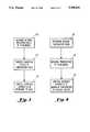
- FIG. 3is a flow chart depicting operation of the system depicted in FIG. 1.
- FIG. 4is a flow chart further depicting operation of the system depicted in FIG. 1.
- System 10for monitoring and controlling the temperature of a film tube during a manufacturing process.
- System 10includes a manufacturing system 12 having an extrusion die head 14 which is, as conventionally known, associated with a polymerization reactor or other source of pressurized liquid polymer so as to eject an extruded product 16 shaped as a continuous tube 18, commonly referred to as a bubble.
- Die gap 15provides for adjusting the thickness of extruded product 16 as the extruded product leaves die head 14, as shown in FIG. 2.
- Extruder screw 19provides for adjusting the speed of ejection of extruded product 16, commonly referred to as the extruder screw speed.
- the extruded product 16congeals at frost line 20.
- tube 18is blown in the vertical direction in FIG. 1 and tube 18 is circular in horizontal cross-section with the film being located around the circumference of the circle and hollow on the inside.
- Die head 14is in communication with an air passage 21 for introducing a gas, such as air, into the interior of tubular portion 18 as extruded product 16 is forced under pressure through die head 14, thus forming tube 18.
- Air passage 21may be communicated with a source P1 of pressurized gas upon the opening of a solenoid actuatable valve VS 1 .
- Die head 14is also in communication with a series of second air passages 23 located around the periphery of die head 14 for blowing external cooling air around the exterior of tube 18.
- Air passages 23may be communicated with a source P2 of pressurized gas upon the opening of a solenoid actuatable valve VS 2 .
- the external cooling air released from passages 23provides for cooling of extruded product 16 as it exits die head 14.
- the interior air and the external cooling air released from passages 21 and 23may be controlled such that the extruded product 16 congeals at a desired distance above die head 14.
- tube 18is tensioned by and passed through a nip roller pair 24 to form flat film 26.
- Film 26is eventually advanced into a storage roll 28 for further handling and distribution.
- system 10includes an infrared camera 32 for measuring the infrared radiation levels of extruded product 16 simultaneously at multiple points on tube 18.
- camera 32simultaneously provides a multi-dimensional profile of the infrared radiation levels of extruded product 16.
- Camera 32may be set up such that it views a desired portion vertically up and down on tube 18.
- camera 32is located a distance from tube 18 such that the camera views the portion of the tube vertically from the top of the die head 14 to above the frost line 20. This provides a complete profile in the vertical direction of the critical area of temperature variation between the die head and the frost line, where the extruded product 16 is in a non-congealed state.
- camera 32is stationary.
- the cameraviews only one particular section around the circumference of tube 18.
- the stationary cameraviews at least 60 degrees around the circumference of the tube.
- camera 32is rotated around tube 18. In the most preferred embodiment, camera 32 is rotated 360 degrees around tube 18. Rotating stand 33 wheels camera 32 around a track along the path of the dashed lines shown in FIG. 1.
- the systemprovides that the infrared radiation level data is continuously collected and stored in memory and converted to data indicative of the temperature of the film.
- the systemprovides a temperature profile circumferentially around at least a portion of tube 18 in a horizontal cross-sectional plane of the tube.
- Controller 34continuously collects and stores the infrared radiation level data from camera 32 in memory in a manner well known in the art. Included in controller 34 is a processor for converting the input radiation levels to data indicative of the temperature at the multiple points on tube 18 in a manner well known in the art. As described in detail below, the extruder apparatus, such as die gap 15, extruder screw 19 and air passages 21 and 23, may be controlled in accordance with the temperature data. In a preferred embodiment, controller 34 is used to automatically control the extruder apparatus using servo motors in a manner well known in the art. In another embodiment, the output of controller 34 is read manually by the system operator at an input/output terminal 36 and the extruder apparatus may be controlled manually in accordance with the temperature data.
- a video display terminal 38is connected to camera 32 for providing a visual image of tube 18 during the film blowing process.
- the frost line point at which the film congealsis a visual phenomena. Accordingly, the frost line location may be viewed and changes in the frost line position may be monitored on video display terminal 38.
- the extruder apparatusmay be more effectively controlled in order to make adjustments to the extruder screw speed and the internal/external air flow around the bubble. These adjustments provide for maintaining the film properties, such as the temperature and film thickness and uniformity, substantially at the desired values which are known to produce the highest quality end product.
- a system 10operates as follows and as shown in the flow chart of FIG. 3.
- camera 32views the film tube 18 as extruded product 16 is blown out of die head 14.
- Camera 32measures the infrared radiation levels simultaneously at multiple points on film tube 18.
- more or less of the tube 18may be viewed.
- camera 32is positioned so as to view tube 18 from at least the top of die head 14 to at least above the frost line 20.
- camera 32is continuously rotated 360 degrees around the circumference of tube 18 so as to provide a view of the entire tube 18.
- the image detected by camera 32may be displayed on video display screen 38.
- the frost linemay be visually detected by the system operator. Therefore, changes in the position of the frost line may be visually monitored and adjustments may be made to the extruder apparatus in order to maintain the frost line at or near a desired location.
- the infrared radiation levels measured by camera 32are input into controller 34 such that the processor converts the radiation levels measured at the multiple points on the film bubble to electrical signals and then further converts the electrical signals to data indicative of the temperature at the multiple points on the film bubble in a manner well known in the art.
- controller 34provides signals for controllinq the extruder apparatus.
- these signalsare read manually by the system operator at input/output terminal 36.
- the system operatorthen provides manual control of the extruder apparatus in accordance with these control signals.
- the film blowing systemis controlled automatically in response to the signals from controller 34 in a manner well known in the art.
- Various apparatus of the film blowing systemmay be controlled in accordance with the signals from controller 34.
- the extruder screw speed at extruder screw 19is controlled in response to signals from controller 34 in order to make adjustments to the speed of ejection of the extruded resin.
- Die gap 15is controlled in order to adjust the film thickness as extruded product 16 leaves die head 14.
- the flow of pressurized air at the interior of film tube 18 and the flow of pressurized external cooling air around the tubemay be controlled as signals from controller 34 are provided to adjust the flow of air through air passages 21 and 23 respectively.
- the present inventionis not intended to be limited to this description and control of the remaining apparatii of the film blowing system may be controlled in accordance with the multi-dimensional temperature profile provided by the infrared camera.
- the desired temperature profileis determined.
- the present inventionprovides for measuring the temperature simultaneously at multiple points on the film bubble at 112 and controlling the system apparatus at 114 in order to maintain the temperature of the film at these points substantially at the desired values. Maintaining the temperature of the film at the multiple control points substantially at the desired values provides that the film resin congeals at a desired height, the frost line location, above the die head 14.
- the temperature of the filmis maintained within about 1.5° F. of the desired value at each control point.
- the film temperatureis maintained within about 1° F. of the desired value at each control point.
- the film temperatureis maintained within about 0.5° F. of the desired value at each control point.
- infrared camera 32provides for a multi-dimensional temperature profile of the film in the non-congealed state between the die head 14 and the frost line 20, a more effective control system is provided and an end product having a desired quality is more consistently produced.
- the multi-dimensional temperature profile of the film bubble provided by infrared imagingmay also be used to determine the thickness of the extruded film.
- the temperature datamay be combined with the standard extruder measurements, such as the extruder output rate and the internal and external air flow rate and temperature, in order to derive the film thickness.
- the system datafilm temperature, output rate, etc.
- coefficientsare determined that represent the relationship of the film temperature and the extruder measurements to the film thickness for a particular film.
- the extruder apparatusmay be controlled to maintain the temperature throughout the film at values which provide a film of a desired thickness.
- the systemis controlled in order to maintain the film thickness substantially at a preselected desired value.
- the film thicknessis maintained within about 5 mils of the preselected value.
- the film thicknessis maintained within about 0.5 mils of the preselected value.
- the film thicknessis maintained within about 0.1 mils of the preselected value.
Landscapes
- Engineering & Computer Science (AREA)
- Mechanical Engineering (AREA)
- Physics & Mathematics (AREA)
- Thermal Sciences (AREA)
- Extrusion Moulding Of Plastics Or The Like (AREA)
- Shaping By String And By Release Of Stress In Plastics And The Like (AREA)
Abstract
Description
Claims (30)
Priority Applications (1)
| Application Number | Priority Date | Filing Date | Title |
|---|---|---|---|
| US07/996,450US5288441A (en) | 1992-12-24 | 1992-12-24 | System and method for extruder frost line detection |
Applications Claiming Priority (1)
| Application Number | Priority Date | Filing Date | Title |
|---|---|---|---|
| US07/996,450US5288441A (en) | 1992-12-24 | 1992-12-24 | System and method for extruder frost line detection |
Publications (1)
| Publication Number | Publication Date |
|---|---|
| US5288441Atrue US5288441A (en) | 1994-02-22 |
Family
ID=25542940
Family Applications (1)
| Application Number | Title | Priority Date | Filing Date |
|---|---|---|---|
| US07/996,450Expired - Fee RelatedUS5288441A (en) | 1992-12-24 | 1992-12-24 | System and method for extruder frost line detection |
Country Status (1)
| Country | Link |
|---|---|
| US (1) | US5288441A (en) |
Cited By (19)
| Publication number | Priority date | Publication date | Assignee | Title |
|---|---|---|---|---|
| US5470216A (en)* | 1993-04-05 | 1995-11-28 | Nippon Petrochmicals Company, Limited | Film manufacturing apparatus with bubble controlling sensor |
| US5651999A (en)* | 1995-08-15 | 1997-07-29 | Pilot Industries, Inc. | Apparatus for testing extruded tubing |
| US5999255A (en)* | 1997-10-09 | 1999-12-07 | Solutia Inc. | Method and apparatus for measuring Raman spectra and physical properties in-situ |
| US6423166B1 (en)* | 1999-04-22 | 2002-07-23 | Ebrahim Simhaee | Method of making collapsed air cell dunnage suitable for inflation |
| EP1600278A1 (en) | 2004-05-18 | 2005-11-30 | betacontrol gmbh mess- und regeltechnik | Method and apparatus for manufacturing flat web products |
| EP1616687A1 (en)* | 2004-07-14 | 2006-01-18 | Kdesign GmbH | Method and apparatus for monitoring the production in the manufacturing of tubular films |
| US20110115111A1 (en)* | 2005-07-13 | 2011-05-19 | Windmoller & Holscher | Method for setting the sizes of blown film tubes as well as a blown film plant comprising a control device for implementing said method |
| KR101133676B1 (en)* | 2009-11-23 | 2012-04-12 | 한국타이어 주식회사 | Apparatus and method for controlling the extrude speed of extruding machine |
| US20160151950A1 (en)* | 2013-07-19 | 2016-06-02 | Windmöller & Hölscher Kg | Apparatus for Producing Films Stretched In-Line |
| WO2018069399A1 (en)* | 2016-10-11 | 2018-04-19 | Windmöller & Hölscher Kg | Method for monitoring a film quality and film machine |
| CN108136657A (en)* | 2015-09-15 | 2018-06-08 | 八千代工业株式会社 | Parison foreign matter detection system |
| EP2670577B1 (en) | 2011-02-03 | 2021-04-07 | battenfeld-cincinnati Germany GmbH | Cooling device and cooling method for an extrudate |
| US11123909B2 (en) | 2013-07-19 | 2021-09-21 | Windmöller & Heilscher KG | Apparatus for producing films stretched in-line |
| CN114230890A (en)* | 2021-11-30 | 2022-03-25 | 广东汇发塑业科技有限公司 | Special aquaculture membrane suitable for Guangdong area |
| US11446854B2 (en)* | 2019-12-16 | 2022-09-20 | Daniel R. Joseph | Method and apparatus for calibration of blown-film extrusion apparatus |
| US11584058B2 (en)* | 2017-07-26 | 2023-02-21 | Delfingen Fr-Anteuil S.A. | Method and device for the production control of an extruded plastic product and extrusion system for extruding such a plastic product |
| WO2023089192A1 (en)* | 2021-11-22 | 2023-05-25 | Windmöller & Hölscher Kg | Method for monitoring a film bubble, and a film-blowing installation |
| CN118225169A (en)* | 2024-03-26 | 2024-06-21 | 思睿观通科技(江苏)股份有限公司 | Plastic film detection device and detection method thereof |
| KR102741739B1 (en)* | 2023-08-24 | 2024-12-19 | ㈜에스제이켐테크 | Medical tube manufacturing apparatus |
Citations (18)
| Publication number | Priority date | Publication date | Assignee | Title |
|---|---|---|---|---|
| US3459841A (en)* | 1965-12-22 | 1969-08-05 | Bernhard Seiler | Container forming method and apparatus |
| US4101614A (en)* | 1975-03-03 | 1978-07-18 | The Dow Chemical Company | Blown film process |
| US4189288A (en)* | 1977-05-13 | 1980-02-19 | Reifenhauser Kg | Apparatus for producing blown synthetic-resin foils and films |
| US4246212A (en)* | 1978-04-17 | 1981-01-20 | Windmoller & Holscher | Method and apparatus for optimizing the output of a blown film extruder plant by means of a process computer |
| US4325897A (en)* | 1979-05-15 | 1982-04-20 | Ludwig Zerle | Method and apparatus for controlling size of extruded tube |
| US4355966A (en)* | 1981-05-04 | 1982-10-26 | E. B. Westlake, Jr. | Automatic control of bubble size in blown film |
| US4402656A (en)* | 1978-11-30 | 1983-09-06 | Gloucester Engineering Co., Inc. | Control of tubular film size |
| US4551289A (en)* | 1983-02-12 | 1985-11-05 | Battenfeld Extrusionstechnik Gmbh | Method of and apparatus for maintaining a constant wall thickness for an extruded article |
| JPS60234821A (en)* | 1984-05-08 | 1985-11-21 | Hiyuutec:Kk | Dimension management of extrusion molded product |
| US4606879A (en)* | 1985-02-28 | 1986-08-19 | Cerisano Frank D | High stalk blown film extrusion apparatus and method |
| DE3628056A1 (en)* | 1985-09-25 | 1987-04-02 | Kunststoff Verarbeitung Gmbh D | Automatically controlling dimensions of extrusions - using e.g. light detect changes in profile or pressure variations just before nozzle outlet to signal to controls |
| US4684487A (en)* | 1984-08-18 | 1987-08-04 | Hoechst Aktiengesellschaft | Process for the control of process parameters in the production of stretched foils |
| US4711747A (en)* | 1985-05-21 | 1987-12-08 | Reifenhauser Gmbh & Co. | Method of producing blown thermoplastic foil with low thickness tolerances |
| US4808359A (en)* | 1985-08-06 | 1989-02-28 | Stamicarbon B.V. | Process for the preparation of cast film |
| US4832897A (en)* | 1984-02-07 | 1989-05-23 | Stamicarbon B.V. | Process for the preparation of blown film |
| US5096634A (en)* | 1990-02-07 | 1992-03-17 | George Aristovoulos Petzetakis | Method of operating an apparatus for the production of biaxially stretched plastic tubes |
| US5124094A (en)* | 1991-03-21 | 1992-06-23 | Minnesota Mining And Manufacturing Company | Apparatus and method for constraining a rotating tube of material |
| US5128076A (en)* | 1991-03-21 | 1992-07-07 | Minnesota Mining And Manufacturing Company | Apparatus and method for producing an elongate strip of material |
- 1992
- 1992-12-24USUS07/996,450patent/US5288441A/ennot_activeExpired - Fee Related
Patent Citations (18)
| Publication number | Priority date | Publication date | Assignee | Title |
|---|---|---|---|---|
| US3459841A (en)* | 1965-12-22 | 1969-08-05 | Bernhard Seiler | Container forming method and apparatus |
| US4101614A (en)* | 1975-03-03 | 1978-07-18 | The Dow Chemical Company | Blown film process |
| US4189288A (en)* | 1977-05-13 | 1980-02-19 | Reifenhauser Kg | Apparatus for producing blown synthetic-resin foils and films |
| US4246212A (en)* | 1978-04-17 | 1981-01-20 | Windmoller & Holscher | Method and apparatus for optimizing the output of a blown film extruder plant by means of a process computer |
| US4402656A (en)* | 1978-11-30 | 1983-09-06 | Gloucester Engineering Co., Inc. | Control of tubular film size |
| US4325897A (en)* | 1979-05-15 | 1982-04-20 | Ludwig Zerle | Method and apparatus for controlling size of extruded tube |
| US4355966A (en)* | 1981-05-04 | 1982-10-26 | E. B. Westlake, Jr. | Automatic control of bubble size in blown film |
| US4551289A (en)* | 1983-02-12 | 1985-11-05 | Battenfeld Extrusionstechnik Gmbh | Method of and apparatus for maintaining a constant wall thickness for an extruded article |
| US4832897A (en)* | 1984-02-07 | 1989-05-23 | Stamicarbon B.V. | Process for the preparation of blown film |
| JPS60234821A (en)* | 1984-05-08 | 1985-11-21 | Hiyuutec:Kk | Dimension management of extrusion molded product |
| US4684487A (en)* | 1984-08-18 | 1987-08-04 | Hoechst Aktiengesellschaft | Process for the control of process parameters in the production of stretched foils |
| US4606879A (en)* | 1985-02-28 | 1986-08-19 | Cerisano Frank D | High stalk blown film extrusion apparatus and method |
| US4711747A (en)* | 1985-05-21 | 1987-12-08 | Reifenhauser Gmbh & Co. | Method of producing blown thermoplastic foil with low thickness tolerances |
| US4808359A (en)* | 1985-08-06 | 1989-02-28 | Stamicarbon B.V. | Process for the preparation of cast film |
| DE3628056A1 (en)* | 1985-09-25 | 1987-04-02 | Kunststoff Verarbeitung Gmbh D | Automatically controlling dimensions of extrusions - using e.g. light detect changes in profile or pressure variations just before nozzle outlet to signal to controls |
| US5096634A (en)* | 1990-02-07 | 1992-03-17 | George Aristovoulos Petzetakis | Method of operating an apparatus for the production of biaxially stretched plastic tubes |
| US5124094A (en)* | 1991-03-21 | 1992-06-23 | Minnesota Mining And Manufacturing Company | Apparatus and method for constraining a rotating tube of material |
| US5128076A (en)* | 1991-03-21 | 1992-07-07 | Minnesota Mining And Manufacturing Company | Apparatus and method for producing an elongate strip of material |
Cited By (27)
| Publication number | Priority date | Publication date | Assignee | Title |
|---|---|---|---|---|
| US5470216A (en)* | 1993-04-05 | 1995-11-28 | Nippon Petrochmicals Company, Limited | Film manufacturing apparatus with bubble controlling sensor |
| US5651999A (en)* | 1995-08-15 | 1997-07-29 | Pilot Industries, Inc. | Apparatus for testing extruded tubing |
| US5999255A (en)* | 1997-10-09 | 1999-12-07 | Solutia Inc. | Method and apparatus for measuring Raman spectra and physical properties in-situ |
| US6696135B2 (en)* | 1999-04-22 | 2004-02-24 | Ebrahim Simhaee | Inflatable air cell dunnage |
| US6423166B1 (en)* | 1999-04-22 | 2002-07-23 | Ebrahim Simhaee | Method of making collapsed air cell dunnage suitable for inflation |
| EP1600278A1 (en) | 2004-05-18 | 2005-11-30 | betacontrol gmbh mess- und regeltechnik | Method and apparatus for manufacturing flat web products |
| EP1616687A1 (en)* | 2004-07-14 | 2006-01-18 | Kdesign GmbH | Method and apparatus for monitoring the production in the manufacturing of tubular films |
| US20110115111A1 (en)* | 2005-07-13 | 2011-05-19 | Windmoller & Holscher | Method for setting the sizes of blown film tubes as well as a blown film plant comprising a control device for implementing said method |
| US9248601B2 (en)* | 2005-07-13 | 2016-02-02 | Windmoeller & Hoelscher Kg | Method for setting the sizes of blown film tubes as well as a blown film plant comprising a control device for implementing said method |
| KR101133676B1 (en)* | 2009-11-23 | 2012-04-12 | 한국타이어 주식회사 | Apparatus and method for controlling the extrude speed of extruding machine |
| EP2670577B1 (en) | 2011-02-03 | 2021-04-07 | battenfeld-cincinnati Germany GmbH | Cooling device and cooling method for an extrudate |
| US20160151950A1 (en)* | 2013-07-19 | 2016-06-02 | Windmöller & Hölscher Kg | Apparatus for Producing Films Stretched In-Line |
| EP3022040B1 (en) | 2013-07-19 | 2018-02-21 | Windmöller & Hölscher KG | Device for producing films stretched in-line |
| EP3022040B2 (en)† | 2013-07-19 | 2022-08-03 | Windmöller & Hölscher KG | Device for producing films stretched in-line |
| US11123909B2 (en) | 2013-07-19 | 2021-09-21 | Windmöller & Heilscher KG | Apparatus for producing films stretched in-line |
| US12202186B2 (en) | 2013-07-19 | 2025-01-21 | Windmöller & Hölscher Kg | Apparatus for producing films stretched in-line |
| CN108136657A (en)* | 2015-09-15 | 2018-06-08 | 八千代工业株式会社 | Parison foreign matter detection system |
| CN108136657B (en)* | 2015-09-15 | 2019-05-17 | 八千代工业株式会社 | Parison foreign matter detection system |
| WO2018069399A1 (en)* | 2016-10-11 | 2018-04-19 | Windmöller & Hölscher Kg | Method for monitoring a film quality and film machine |
| US11141904B2 (en)* | 2016-10-11 | 2021-10-12 | Windmöller & Hölscher Kg | Method for monitoring a film quality and film machine |
| US11584058B2 (en)* | 2017-07-26 | 2023-02-21 | Delfingen Fr-Anteuil S.A. | Method and device for the production control of an extruded plastic product and extrusion system for extruding such a plastic product |
| US11446854B2 (en)* | 2019-12-16 | 2022-09-20 | Daniel R. Joseph | Method and apparatus for calibration of blown-film extrusion apparatus |
| WO2023089192A1 (en)* | 2021-11-22 | 2023-05-25 | Windmöller & Hölscher Kg | Method for monitoring a film bubble, and a film-blowing installation |
| CN114230890A (en)* | 2021-11-30 | 2022-03-25 | 广东汇发塑业科技有限公司 | Special aquaculture membrane suitable for Guangdong area |
| KR102741739B1 (en)* | 2023-08-24 | 2024-12-19 | ㈜에스제이켐테크 | Medical tube manufacturing apparatus |
| CN118225169A (en)* | 2024-03-26 | 2024-06-21 | 思睿观通科技(江苏)股份有限公司 | Plastic film detection device and detection method thereof |
| CN118225169B (en)* | 2024-03-26 | 2024-08-09 | 思睿观通科技(江苏)股份有限公司 | Plastic film detection device and detection method thereof |
Similar Documents
| Publication | Publication Date | Title |
|---|---|---|
| US5288441A (en) | System and method for extruder frost line detection | |
| US5676893A (en) | Cooling and thickness control for extruded products | |
| US4189288A (en) | Apparatus for producing blown synthetic-resin foils and films | |
| US5288219A (en) | Air ring for controlling blown film thickness | |
| US4174932A (en) | Apparatus for extruding tubular thermoplastic film | |
| US5258148A (en) | Process for controlling the degree of orientation of tubular films | |
| US3265789A (en) | Method and apparatus for forming thermoplastic films | |
| US2559386A (en) | Manufacture of lay flat tubing | |
| US4101614A (en) | Blown film process | |
| KR102308063B1 (en) | Apparatus for manufacturing a blown film | |
| US5135689A (en) | Method of measuring thickness of extruded films | |
| US3207823A (en) | Production of flattened tubular plastic film | |
| EP1616687A1 (en) | Method and apparatus for monitoring the production in the manufacturing of tubular films | |
| US5683727A (en) | Apparatus for the production of blown foils or films of thermoplastic | |
| CA2330955C (en) | Method and apparatus for lay flat control in an extruded film production line | |
| US6922608B2 (en) | Method and apparatus for lay flat control in an extruded film production line | |
| CN109789628A (en) | Method and apparatus for manufacturing plastic film | |
| US20060216369A1 (en) | Method for control of the thickness of extruded film | |
| JPH01317743A (en) | Production of inflation film | |
| JPH05138733A (en) | Frost line control device in inflation molding line | |
| JPS5942612B2 (en) | Automatic adjustment of frost line in inflation film manufacturing method | |
| CN116653273B (en) | Plastic film blowing process and control method | |
| GB2024702A (en) | Blown film process | |
| US20250237556A1 (en) | Method and measuring arrangement for determining the position of a frost line in the manufacture of a tubular film of thermoplastic material | |
| IT201900011751A1 (en) | SYSTEM AND METHOD FOR CHECKING AND CORRECTING THE THICKNESS OF A PLASTIC FILM IN BLOWING FILM |
Legal Events
| Date | Code | Title | Description |
|---|---|---|---|
| AS | Assignment | Owner name:WISSING, WILLIAM K., NEW JERSEY Free format text:CORRECTIVE ASSIGNMENT FROM PREVIOUS REEL 6423 FRAME 996.;ASSIGNOR:COLLINS, STEVEN L.;REEL/FRAME:006926/0724 Effective date:19930104 Owner name:WISSING, WILLIAM K., ESQ., NEW JERSEY Free format text:ASSIGNMENT OF ASSIGNORS INTEREST.;ASSIGNOR:COLLINS, STEVEN L.;REEL/FRAME:006423/0996 Effective date:19930104 | |
| AS | Assignment | Owner name:UNION CAMP CORPORATION, NEW JERSEY Free format text:TO CORRECT ASSIGNMENT PREVIOUSLY RECORDED ON REEL 6926, FRAME 724;ASSIGNOR:COLLINS, STEVEN L.;REEL/FRAME:007029/0660 Effective date:19930104 | |
| FEPP | Fee payment procedure | Free format text:PAYOR NUMBER ASSIGNED (ORIGINAL EVENT CODE: ASPN); ENTITY STATUS OF PATENT OWNER: LARGE ENTITY | |
| FPAY | Fee payment | Year of fee payment:4 | |
| FEPP | Fee payment procedure | Free format text:PAYER NUMBER DE-ASSIGNED (ORIGINAL EVENT CODE: RMPN); ENTITY STATUS OF PATENT OWNER: LARGE ENTITY Free format text:PAYOR NUMBER ASSIGNED (ORIGINAL EVENT CODE: ASPN); ENTITY STATUS OF PATENT OWNER: LARGE ENTITY | |
| FPAY | Fee payment | Year of fee payment:8 | |
| REMI | Maintenance fee reminder mailed | ||
| LAPS | Lapse for failure to pay maintenance fees | ||
| LAPS | Lapse for failure to pay maintenance fees | Free format text:PATENT EXPIRED FOR FAILURE TO PAY MAINTENANCE FEES (ORIGINAL EVENT CODE: EXP.); ENTITY STATUS OF PATENT OWNER: LARGE ENTITY | |
| STCH | Information on status: patent discontinuation | Free format text:PATENT EXPIRED DUE TO NONPAYMENT OF MAINTENANCE FEES UNDER 37 CFR 1.362 | |
| FP | Lapsed due to failure to pay maintenance fee | Effective date:20060222 |