US5286064A - Sealing plate for a pipe coupling - Google Patents
Sealing plate for a pipe couplingDownload PDFInfo
- Publication number
- US5286064A US5286064AUS07/861,940US86194092AUS5286064AUS 5286064 AUS5286064 AUS 5286064AUS 86194092 AUS86194092 AUS 86194092AUS 5286064 AUS5286064 AUS 5286064A
- Authority
- US
- United States
- Prior art keywords
- axial
- sealing
- plate
- pair
- coupling
- Prior art date
- Legal status (The legal status is an assumption and is not a legal conclusion. Google has not performed a legal analysis and makes no representation as to the accuracy of the status listed.)
- Expired - Lifetime
Links
Images


Classifications
- F—MECHANICAL ENGINEERING; LIGHTING; HEATING; WEAPONS; BLASTING
- F16—ENGINEERING ELEMENTS AND UNITS; GENERAL MEASURES FOR PRODUCING AND MAINTAINING EFFECTIVE FUNCTIONING OF MACHINES OR INSTALLATIONS; THERMAL INSULATION IN GENERAL
- F16L—PIPES; JOINTS OR FITTINGS FOR PIPES; SUPPORTS FOR PIPES, CABLES OR PROTECTIVE TUBING; MEANS FOR THERMAL INSULATION IN GENERAL
- F16L55/00—Devices or appurtenances for use in, or in connection with, pipes or pipe systems
- F16L55/16—Devices for covering leaks in pipes or hoses, e.g. hose-menders
- F16L55/168—Devices for covering leaks in pipes or hoses, e.g. hose-menders from outside the pipe
- F16L55/17—Devices for covering leaks in pipes or hoses, e.g. hose-menders from outside the pipe by means of rings, bands or sleeves pressed against the outside surface of the pipe or hose
- F16L55/172—Devices for covering leaks in pipes or hoses, e.g. hose-menders from outside the pipe by means of rings, bands or sleeves pressed against the outside surface of the pipe or hose the ring, band or sleeve being tightened by a tangentially arranged threaded pin and a nut
- F—MECHANICAL ENGINEERING; LIGHTING; HEATING; WEAPONS; BLASTING
- F16—ENGINEERING ELEMENTS AND UNITS; GENERAL MEASURES FOR PRODUCING AND MAINTAINING EFFECTIVE FUNCTIONING OF MACHINES OR INSTALLATIONS; THERMAL INSULATION IN GENERAL
- F16L—PIPES; JOINTS OR FITTINGS FOR PIPES; SUPPORTS FOR PIPES, CABLES OR PROTECTIVE TUBING; MEANS FOR THERMAL INSULATION IN GENERAL
- F16L21/00—Joints with sleeve or socket
- F16L21/06—Joints with sleeve or socket with a divided sleeve or ring clamping around the pipe ends
- Y—GENERAL TAGGING OF NEW TECHNOLOGICAL DEVELOPMENTS; GENERAL TAGGING OF CROSS-SECTIONAL TECHNOLOGIES SPANNING OVER SEVERAL SECTIONS OF THE IPC; TECHNICAL SUBJECTS COVERED BY FORMER USPC CROSS-REFERENCE ART COLLECTIONS [XRACs] AND DIGESTS
- Y10—TECHNICAL SUBJECTS COVERED BY FORMER USPC
- Y10S—TECHNICAL SUBJECTS COVERED BY FORMER USPC CROSS-REFERENCE ART COLLECTIONS [XRACs] AND DIGESTS
- Y10S285/00—Pipe joints or couplings
- Y10S285/91—Gaskets
- Y—GENERAL TAGGING OF NEW TECHNOLOGICAL DEVELOPMENTS; GENERAL TAGGING OF CROSS-SECTIONAL TECHNOLOGIES SPANNING OVER SEVERAL SECTIONS OF THE IPC; TECHNICAL SUBJECTS COVERED BY FORMER USPC CROSS-REFERENCE ART COLLECTIONS [XRACs] AND DIGESTS
- Y10—TECHNICAL SUBJECTS COVERED BY FORMER USPC
- Y10S—TECHNICAL SUBJECTS COVERED BY FORMER USPC CROSS-REFERENCE ART COLLECTIONS [XRACs] AND DIGESTS
- Y10S285/00—Pipe joints or couplings
- Y10S285/915—Mastic
- Y—GENERAL TAGGING OF NEW TECHNOLOGICAL DEVELOPMENTS; GENERAL TAGGING OF CROSS-SECTIONAL TECHNOLOGIES SPANNING OVER SEVERAL SECTIONS OF THE IPC; TECHNICAL SUBJECTS COVERED BY FORMER USPC CROSS-REFERENCE ART COLLECTIONS [XRACs] AND DIGESTS
- Y10—TECHNICAL SUBJECTS COVERED BY FORMER USPC
- Y10T—TECHNICAL SUBJECTS COVERED BY FORMER US CLASSIFICATION
- Y10T29/00—Metal working
- Y10T29/49—Method of mechanical manufacture
- Y10T29/49718—Repairing
- Y10T29/49732—Repairing by attaching repair preform, e.g., remaking, restoring, or patching
- Y10T29/49739—Mechanically attaching preform by separate fastener
Definitions
- the present inventionrelates to couplings for sealing leak locations in pipe lines, including joints between adjacent pipe ends, and particularly relates to a sealing plate for use in sealing the axial joint of a pipe coupling.
- Sealing joints and other leak locations in pipelineshas always been a critical concern, and has become more important as efforts have increased to protect the environment. Liquid chemicals, sewage, toxic gases, and other fluid-like materials such as fine dust must be conducted through pipelines without leakage of the material from the pipeline and without contamination from outside.
- pipeline installerstypically encircle the joint with a cylindrical coupling consisting of either two semi-cylindrical pieces fastened together to clamp down on the pipe ends, or a single cylindrical piece having an axial slit which allows the coupling to be opened by an amount sufficient to fit over the pipe ends.
- Annular gasket memberssuch as O-rings, may be placed around the pipe ends beneath the coupling to block the escape of fluid axially between the coupling and the pipe ends, but it is then necessary to block escape of fluid outwardly through the axial slit of the coupling.
- Several prior devices for this purposehave been developed, as described in U.S. Pat. Nos. 4,360,227; 1,607,943; 2,913,262; 3,153,550; 4,664,428, and 5,086,809.
- U.S. Pat. No. 4,664,4208which is incorporated herein by reference in its entirety, describes a sealing plate spanning the axial slit of a coupling and contacting two O-rings positioned on opposite sides of the joint in the pipeline.
- the sealing plateis positioned outside the O-rings between them and the coupling and has axial gaskets along edges of the sealing plate for preventing passage of fluid from between the O-rings to the outer surface of the sealing plate.
- This sealing platehas the disadvantage, however, that it can only be used with continuous annular O-rings which must be properly positioned on the pipe ends before positioning the sealing plate over the O-rings and then positioning the coupling over the sealing plate and O-rings.
- Couplings having arcuate gasket members attached to the inside of the couplingcannot be used with such a sealing plate.
- the O-ringsmay become misaligned or the sealing plate may become misaligned with respect to the O-rings.
- the present inventionsolves the above problems in the art by providing a sealing plate which is positioned under annular O-rings or built-in coupling gaskets.
- the sealing platecarries gasket material on its inner surface to complete an annular seal around the pipeline on either side of a leak location, and on its outer surface to prevent fluid from reaching the axial joint of the coupling between the annular seal.
- An advantage of the sealing plate of the inventionis that once one positions the sealing plate properly, the annular gasket material does not become misaligned.
- the sealing platecan be used interchangeably with discrete O-rings and a coupling, or with a coupling having built-in arcuate gasket sections.
- the present inventionprovides a sealing plate for use with a pipe coupling surrounding a leak location in a pipeline, comprising a plate having a pair of axial edges along opposite ends of the plate and a pair of side edges along opposite sides of the plate; a pair of axial sealing pads, one adhered to an outer surface of the plate along each of the axial edges, each axial sealing pad defining a pair of spaced apart circumferential guide channels therein and a bridging member connecting the guide channels, the bridging member shaped to be engaged when an inner surface of a coupling is pressed toward the outer surface of the plate; and a pair of spaced apart circumferential sealing pads adhered to an inner surface of the plate.
- the axial sealing padextends beyond each of the axial edges at the location of the guide channels and the circumferential sealing pads extend beyond the axial edges and are attached to the axial sealing pads at opposite ends of the circumferential sealing pads.
- each of the guide channelsis defined by a pair of spaced apart humps positioned adjacent to a side edge of the plate, and the bridging member connecting the guide channels comprises an axial ridge connecting the inner humps of the two pair of humps defining the two guide channels of each of the axial sealing pads.
- the axial ridgemay extend beyond the inner humps into the guide channels to form a more positive seal between the bridging member and arcuate gasket members received in the guide channels.
- the sealing platecooperates with a pair of arcuate gaskets positioned around the pipeline one on each side of the leak location, each of the arcuate gaskets engaging both of the axial sealing pads in respective guide channels; and an annular coupling having at least one axial joint, the coupling being positioned around the arcuate gaskets with its axial joint positioned over the sealing plate, the coupling being closable to engage an inner surface of the coupling with the gaskets and with the bridging members, and to engage the circumferential sealing pads with the pipeline on either side of the leak location.
- the arcuate gasketsmay be attached to the inner surface of the coupling, or may be annular O-rings positioned around the sealing plate. Annular O-rings in such a configuration help to retain the sealing plate in position while the coupling is closed, and the guide channels of the sealing plate in turn help to retain the O-rings in proper position.
- the present inventionalso provides an elongate gasket member comprising a rounded side and a flattened side intersecting along a pair of mutual edges, the flattened side including a ridge intermediate the edges.
- a gasket membermay be built into a coupling by adhering the gasket member within grooves defined in the inner surface of the coupling.
- FIG. 1is a top pictorial view of a sealing plate embodying the present invention.
- FIG. 2is a bottom pictorial view of the sealing plate of FIG. 1.
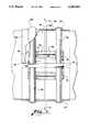
- FIG. 3is a top plan view of a pipe joint with a sealing plate embodying the invention installed therein, with portions of the coupling broken away.
- FIG. 4is a radial cross-sectional view taken along line 4--4 of FIG. 3.
- FIG. 5is an end view of the sealing plate of FIG. 1, showing one side as installed on a pipe end under a coupling.
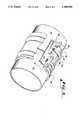
- FIG. 6is a pictorial view of the sealing plate installed in a pipe joint, with portions of the coupling broken away.
- FIG. 7is a cross-sectional view of an elongate gasket material used in a pipe joint embodying the invention.
- FIG. 1shows a sealing plate 10 embodying the present invention.
- the sealing plate 10includes a central plate member 12, preferably made of steel.
- the rectangular plate member 12is curved to match the circumference of the pipe line with which it will be used, and defines a pair of opposing axial edges 14 connected by a pair of opposing circumferential edges 15.
- the plate member 12has an outer surface 16 which faces away from the center of the pipeline when installed, and an inner surface 17, visible in FIG. 2.
- Two axial sealing pads 20are attached to the outer surface 16 of the plate 12, one along each of the axial edges 14.
- Each of the axial sealing pads 20is triangular in cross section.
- a broad, elongate face 21 of the triangular padfaces the axial edge 14, and an apex ridge 22 is formed at the apex of the triangle.
- the axial sealing pad 20extends beyond the axial edge 14 of the plate 12 to form a skirt 24.
- the skirtextends down over the axial edge 14 at a shoulder 25 formed in the material of the axial sealing pad 20.
- Each axial sealing pad 20also defines a plurality of approximately cone shaped humps which extend circumferentially from a point adjacent to the apex ridge 22 down the broad face 21 and onto the skirt 24, with the base 31 of each cone positioned adjacent to the edge of the skirt 24.
- Two outer humps 30, shaped as just described,are positioned a short distance inwardly from the circumferential edges 15.
- Two inner humps 33are positioned on the axial sealing pads 20 a short distance inwardly from each of the outer humps 30.
- the pairs of adjacent humps 30, 33form between them two guide channels 34 for receiving O-rings, as described below.
- a thick axial ridge 36extends between and connects the inner humps 33.
- the axial ridge 36must be sufficiently high that a coupling installed over the sealing plate will engage the axial ridge 36 along its entire length, in the manner shown in FIGS. 4 and 5.
- the axial ridge 36has a pair of extensions 37, one extending on each end of the axial ridge 36 past the inner humps 33 into the guide channels 34. The purpose of the extensions 37 is to provide a better sealing engagement with O-rings positioned in the guide channels 34.
- a pair of spaced apart circumferential sealing pads 40are attached to the inner surface 17 of the plate members 12.
- the two circumferential sealing pads 40are positioned so as to extend past the axial edges 14 of the plate 12 for attachment to the inner surface of the skirt 24 at the location of the guide channels 34.
- the circumferential sealing pads 40are formed by strips of gasket material molded or extruded with an approximately half-circular central protrusion 42 at the center of the pad 40.
- the central protrusion 42extends along the length of the pad 40.
- the axial and circumferential sealing padsare preferably made of rubber having a hardness of 40 to 70 Durometer.
- the axial sealing padsare adhered to the metal plate 12 preferably by a well known chemical vulcanization process.
- the axial and circumferential sealing padsare adhered to one another preferably by conventional vulcanization process, which may be a heat/pressure vulcanization process.
- FIGS. 3-6Use of the sealing plate 10 to seal a joint between adjacent pipe ends 44 and 45 is shown in FIGS. 3-6.
- the sealing plateis positioned directly on the pipe line with the circumferential sealing pads 40 extending parallel and on opposite sides of the gap between the pipe ends.
- the axial sealing pads 20extend along the pipe line and perpendicular to the gap.
- the sealing plate 10 according to the present inventionis positioned under the arcuate gaskets which surround the pipe ends. This allows the sealing plate to be used both with separate circular O-rings and with arcuate gasket segments built into the inner surface of a coupling.
- FIGS. 3-6show a coupling 50 which has at least one axial slit 52 and includes a pair of upstanding clamping flanges 53 which can be bolted together to close the axial slit and thus press the coupling 50 against the outer circumferential surface of the pipe line and the sealing plate.
- a pair of annular recesses 55are formed in the inner surface of the coupling, spaced apart by the same distance as the guide channels 34 of the sealing plate 10.
- An arcuate gasket section 60is vulcanized into each of these annular recesses, and extends to both sides of the axial slit 52 of the coupling.
- the arcuate gasket segments 60need only extend to a position between the sealing pads 20 and the flanges 53. It will often be convenient to form the coupling 50 as a pair of semi-circular coupling segments (not shown) so that there are two axial slits requiring two sealing plates 10 to form the pipe joint. Both such joints may be identical to the joint shown in FIGS. 3-6.
- the coupling 50is placed over the pipe ends with an axial slit 52 positioned over the central area of the plate 12 and with arcuate gasket members 60 crossing the axial sealing pads 20 in the guide channels 34. This is shown in FIG. 3 from directly above the sealing plate 10, with the outline of the coupling shown in dashed lines.
- the arcuate gasket materialis compressed into the guide channels 34 and comes into engagement with the humps 30 and 33.
- the arcuate gaskets 60also engage and compress the extensions 37 of the axial ridges 36, as best shown in FIG. 5.
- FIG. 7shows a preferred cross section for the gasket material used to form the arcuate gasket 60.
- the gasket 60defines a rounded side 62 extending about 240 degrees around the circumference of the gasket material, with the remaining portion 63 being generally flattened.
- a slight ridge 64extends outwardly along the center of the flattened portion.
- the preferred shape as shown in FIG. 7resembles a medallion or shield.
- the rounded side 62is received within the guide channels 34 of the axial sealing pads 20.
- the ridge 64therefore points outwardly to form a tight seal with the surrounding coupling.
- the flattened portion 63is received within and vulcanized to the inner recesses 55 of the coupling 50.
- a sealing plate embodying the present inventiondiffers in significant respects from prior sealing plates and provides significant advantages.
- the sealing plate 10is placed under the O-rings so that the circumferential seal is transferred from the O-rings to the circumferential sealing pads 40, while the axial ridges 36 completes the sealing of the axial slit of the coupling.
- the sealing platesimplifies installation which consists of placing the sealing plate against the pipe ends across the joint, placing the coupling or the sections of the coupling around the pipe ends with the O-ring segments in the guide channels of the sealing plate, and tightening the coupling.
Landscapes
- Engineering & Computer Science (AREA)
- General Engineering & Computer Science (AREA)
- Mechanical Engineering (AREA)
- Pipe Accessories (AREA)
- Gasket Seals (AREA)
Abstract
Description
Claims (21)
Priority Applications (4)
| Application Number | Priority Date | Filing Date | Title |
|---|---|---|---|
| US07/861,940US5286064A (en) | 1992-04-02 | 1992-04-02 | Sealing plate for a pipe coupling |
| US07/978,770US5295716A (en) | 1992-04-02 | 1992-11-19 | Pipe coupling with sealing plate |
| US08/160,956US5383496A (en) | 1992-04-02 | 1993-12-03 | Coupling with offset closure |
| US08/215,499US5362107A (en) | 1992-04-02 | 1994-03-21 | Pipe coupling with sealing plate |
Applications Claiming Priority (1)
| Application Number | Priority Date | Filing Date | Title |
|---|---|---|---|
| US07/861,940US5286064A (en) | 1992-04-02 | 1992-04-02 | Sealing plate for a pipe coupling |
Related Child Applications (1)
| Application Number | Title | Priority Date | Filing Date |
|---|---|---|---|
| US07/978,770Continuation-In-PartUS5295716A (en) | 1992-04-02 | 1992-11-19 | Pipe coupling with sealing plate |
Publications (1)
| Publication Number | Publication Date |
|---|---|
| US5286064Atrue US5286064A (en) | 1994-02-15 |
Family
ID=25337162
Family Applications (2)
| Application Number | Title | Priority Date | Filing Date |
|---|---|---|---|
| US07/861,940Expired - LifetimeUS5286064A (en) | 1992-04-02 | 1992-04-02 | Sealing plate for a pipe coupling |
| US07/978,770Expired - LifetimeUS5295716A (en) | 1992-04-02 | 1992-11-19 | Pipe coupling with sealing plate |
Family Applications After (1)
| Application Number | Title | Priority Date | Filing Date |
|---|---|---|---|
| US07/978,770Expired - LifetimeUS5295716A (en) | 1992-04-02 | 1992-11-19 | Pipe coupling with sealing plate |
Country Status (1)
| Country | Link |
|---|---|
| US (2) | US5286064A (en) |
Cited By (12)
| Publication number | Priority date | Publication date | Assignee | Title |
|---|---|---|---|---|
| US5383496A (en)* | 1992-04-02 | 1995-01-24 | Donald Y. Bridges | Coupling with offset closure |
| US5533760A (en)* | 1994-06-23 | 1996-07-09 | Shell Oil Company | Method and device for containing fluids |
| US5765876A (en)* | 1995-11-24 | 1998-06-16 | Bridges; Donald Y. | Pipe coupling requiring low closing force |
| US5769467A (en)* | 1995-10-10 | 1998-06-23 | Bridges; Donald Y. | Pipe couplings for misaligned or out-of-round pipes and expanding/contracting pipes |
| US6024363A (en)* | 1996-09-30 | 2000-02-15 | Johnson, Jr.; Theodore C. | Gasket for use with an air brake hose coupling member |
| US20050066480A1 (en)* | 2004-03-26 | 2005-03-31 | Aba Of Sweden Ab | Band clamp |
| US20050179260A1 (en)* | 2002-05-17 | 2005-08-18 | Jan Sedlacek | Pipe clamp |
| US20070052238A1 (en)* | 2003-10-17 | 2007-03-08 | An Byung-Moo | Band device of joining pipe for preventing from leakage |
| US20070182230A1 (en)* | 2006-02-06 | 2007-08-09 | Toyota Engineering & Manufacturing North America, Inc. | Seat Assembly Having Integrated Belt, Storage Compartments And Registers |
| US20070279387A1 (en)* | 2006-05-31 | 2007-12-06 | Velimir Pletikosa | Pivoting, Multi-Configuration Mobile Device |
| US20190195401A1 (en)* | 2017-12-22 | 2019-06-27 | Jun He Technology Co., Ltd. | Sealing ring |
| US11280436B2 (en)* | 2019-02-26 | 2022-03-22 | Krausz Industries Ltd. | Pipe coupling with protection against fastener shearing |
Families Citing this family (9)
| Publication number | Priority date | Publication date | Assignee | Title |
|---|---|---|---|---|
| US5605357A (en)* | 1995-06-05 | 1997-02-25 | M&Fc Holding Co. | Pipe collar |
| GB2310903B (en)* | 1996-03-05 | 1999-12-15 | Avk Mfg Ltd | A pipe repair or jointing collar |
| WO2006066328A1 (en)* | 2004-12-22 | 2006-06-29 | John Gerred Reynen | Hose repair method and apparatus |
| US7950701B2 (en) | 2007-05-15 | 2011-05-31 | Victaulic Company | Pipe coupling having movable gripping bodies |
| KR100912732B1 (en)* | 2007-07-12 | 2009-08-19 | 김선관 | Drain pipe |
| AU2009209007B2 (en)* | 2008-01-30 | 2014-07-24 | Norma U.S. Holding Llc | Single-bolt band clamp with gasketed center rib and pipe lap joint using the same |
| US8556302B2 (en) | 2011-04-05 | 2013-10-15 | Victaulic Company | Pivoting pipe coupling having a movable gripping body |
| CA2877703A1 (en)* | 2012-06-28 | 2014-01-03 | Victaulic Company | Pipe repair clamp assembly |
| RU195009U1 (en)* | 2019-04-11 | 2020-01-13 | Денис Витальевич Кащеев | Percussion Idiophone Instrument |
Citations (24)
| Publication number | Priority date | Publication date | Assignee | Title |
|---|---|---|---|---|
| US1059592A (en)* | 1912-06-01 | 1913-04-22 | James A Belden | Device to hold joints together. |
| US1607943A (en)* | 1925-04-14 | 1926-11-23 | Stewarts & Lloyds Ltd | Joint for pipes and other fluid conveyers and containers |
| US1790957A (en)* | 1931-02-03 | Seal i-ob vacuum jabs | ||
| US2245153A (en)* | 1939-05-04 | 1941-06-10 | Arthur T Mcwane | Pipe joint |
| GB763665A (en)* | 1954-10-27 | 1956-12-12 | Herbert Sydney Jeffery | Improvements relating to pipe collars |
| GB790109A (en)* | 1956-11-12 | 1958-02-05 | Eisenwerke Fried Wilh Duker Ag | Pipe coupling |
| US2849244A (en)* | 1955-12-19 | 1958-08-26 | Sp Mfg Corp | O-ring seal for rotary hydraulic cylinder |
| US2913262A (en)* | 1957-07-01 | 1959-11-17 | On Mark Couplings Inc | Split coupling for joining beaded tubes |
| US3153550A (en)* | 1964-03-13 | 1964-10-20 | Hollett Alec William | Split coupling with an integrally formed one-piece gasket |
| US3479066A (en)* | 1967-07-03 | 1969-11-18 | Morris Gittleman | Pipe coupling |
| US3712631A (en)* | 1971-08-02 | 1973-01-23 | Ecodyne Cooling Prod | Pipe seal |
| US3823216A (en)* | 1971-07-19 | 1974-07-09 | Petzetakis Aristovoulos George | Method of making a pipe-coupling part |
| US4108481A (en)* | 1976-12-06 | 1978-08-22 | United States Pipe And Foundry Company | Gasketed pipe joint |
| US4172607A (en)* | 1978-01-23 | 1979-10-30 | Norton Bernard W | Pipe coupling with plastic sheath |
| DE3017632A1 (en)* | 1980-05-08 | 1981-11-12 | Robert Edmund 6634 Wallerfangen Kornbrust | Sealing leak in pressurised pipe - polyester is applied to edge of sand-blasted strip on seal round leak |
| US4303103A (en)* | 1978-03-31 | 1981-12-01 | Helmuth Marks | Internal sleeve seal and method of use |
| US4360227A (en)* | 1980-02-01 | 1982-11-23 | Bridges Donald Y | Pipe coupling with improved gasket |
| US4583770A (en)* | 1982-11-04 | 1986-04-22 | Oy Wiik & Hoglund Ab | Pipe joint seal |
| US4652023A (en)* | 1984-02-13 | 1987-03-24 | Timmons Fred A | Repair coupler |
| US4653782A (en)* | 1985-02-18 | 1987-03-31 | British Gas Corporation | Pipe repair clamp |
| US4664428A (en)* | 1986-04-01 | 1987-05-12 | Brico Industries, Inc. | Sealing assembly for pipe joint |
| US4944498A (en)* | 1987-07-17 | 1990-07-31 | Stabilus Gmbh | Gas spring |
| US5076618A (en)* | 1989-10-13 | 1991-12-31 | Bridges Donald Y | Method and apparatus for sealing pipe joints from the interior thereof |
| US5086809A (en)* | 1990-06-12 | 1992-02-11 | Bridges Donald Y | Pipe coupling and sealing device |
- 1992
- 1992-04-02USUS07/861,940patent/US5286064A/ennot_activeExpired - Lifetime
- 1992-11-19USUS07/978,770patent/US5295716A/ennot_activeExpired - Lifetime
Patent Citations (24)
| Publication number | Priority date | Publication date | Assignee | Title |
|---|---|---|---|---|
| US1790957A (en)* | 1931-02-03 | Seal i-ob vacuum jabs | ||
| US1059592A (en)* | 1912-06-01 | 1913-04-22 | James A Belden | Device to hold joints together. |
| US1607943A (en)* | 1925-04-14 | 1926-11-23 | Stewarts & Lloyds Ltd | Joint for pipes and other fluid conveyers and containers |
| US2245153A (en)* | 1939-05-04 | 1941-06-10 | Arthur T Mcwane | Pipe joint |
| GB763665A (en)* | 1954-10-27 | 1956-12-12 | Herbert Sydney Jeffery | Improvements relating to pipe collars |
| US2849244A (en)* | 1955-12-19 | 1958-08-26 | Sp Mfg Corp | O-ring seal for rotary hydraulic cylinder |
| GB790109A (en)* | 1956-11-12 | 1958-02-05 | Eisenwerke Fried Wilh Duker Ag | Pipe coupling |
| US2913262A (en)* | 1957-07-01 | 1959-11-17 | On Mark Couplings Inc | Split coupling for joining beaded tubes |
| US3153550A (en)* | 1964-03-13 | 1964-10-20 | Hollett Alec William | Split coupling with an integrally formed one-piece gasket |
| US3479066A (en)* | 1967-07-03 | 1969-11-18 | Morris Gittleman | Pipe coupling |
| US3823216A (en)* | 1971-07-19 | 1974-07-09 | Petzetakis Aristovoulos George | Method of making a pipe-coupling part |
| US3712631A (en)* | 1971-08-02 | 1973-01-23 | Ecodyne Cooling Prod | Pipe seal |
| US4108481A (en)* | 1976-12-06 | 1978-08-22 | United States Pipe And Foundry Company | Gasketed pipe joint |
| US4172607A (en)* | 1978-01-23 | 1979-10-30 | Norton Bernard W | Pipe coupling with plastic sheath |
| US4303103A (en)* | 1978-03-31 | 1981-12-01 | Helmuth Marks | Internal sleeve seal and method of use |
| US4360227A (en)* | 1980-02-01 | 1982-11-23 | Bridges Donald Y | Pipe coupling with improved gasket |
| DE3017632A1 (en)* | 1980-05-08 | 1981-11-12 | Robert Edmund 6634 Wallerfangen Kornbrust | Sealing leak in pressurised pipe - polyester is applied to edge of sand-blasted strip on seal round leak |
| US4583770A (en)* | 1982-11-04 | 1986-04-22 | Oy Wiik & Hoglund Ab | Pipe joint seal |
| US4652023A (en)* | 1984-02-13 | 1987-03-24 | Timmons Fred A | Repair coupler |
| US4653782A (en)* | 1985-02-18 | 1987-03-31 | British Gas Corporation | Pipe repair clamp |
| US4664428A (en)* | 1986-04-01 | 1987-05-12 | Brico Industries, Inc. | Sealing assembly for pipe joint |
| US4944498A (en)* | 1987-07-17 | 1990-07-31 | Stabilus Gmbh | Gas spring |
| US5076618A (en)* | 1989-10-13 | 1991-12-31 | Bridges Donald Y | Method and apparatus for sealing pipe joints from the interior thereof |
| US5086809A (en)* | 1990-06-12 | 1992-02-11 | Bridges Donald Y | Pipe coupling and sealing device |
Cited By (14)
| Publication number | Priority date | Publication date | Assignee | Title |
|---|---|---|---|---|
| US5383496A (en)* | 1992-04-02 | 1995-01-24 | Donald Y. Bridges | Coupling with offset closure |
| US5533760A (en)* | 1994-06-23 | 1996-07-09 | Shell Oil Company | Method and device for containing fluids |
| US5769467A (en)* | 1995-10-10 | 1998-06-23 | Bridges; Donald Y. | Pipe couplings for misaligned or out-of-round pipes and expanding/contracting pipes |
| US5765876A (en)* | 1995-11-24 | 1998-06-16 | Bridges; Donald Y. | Pipe coupling requiring low closing force |
| US6024363A (en)* | 1996-09-30 | 2000-02-15 | Johnson, Jr.; Theodore C. | Gasket for use with an air brake hose coupling member |
| US6290238B1 (en) | 1996-09-30 | 2001-09-18 | New York Air Brake Corporation | Gasket for use with an air brake hose coupling member |
| US20050179260A1 (en)* | 2002-05-17 | 2005-08-18 | Jan Sedlacek | Pipe clamp |
| US7497485B2 (en)* | 2003-10-17 | 2009-03-03 | An Byung-Moo | Band device of joining pipe for preventing from leakage |
| US20070052238A1 (en)* | 2003-10-17 | 2007-03-08 | An Byung-Moo | Band device of joining pipe for preventing from leakage |
| US20050066480A1 (en)* | 2004-03-26 | 2005-03-31 | Aba Of Sweden Ab | Band clamp |
| US20070182230A1 (en)* | 2006-02-06 | 2007-08-09 | Toyota Engineering & Manufacturing North America, Inc. | Seat Assembly Having Integrated Belt, Storage Compartments And Registers |
| US20070279387A1 (en)* | 2006-05-31 | 2007-12-06 | Velimir Pletikosa | Pivoting, Multi-Configuration Mobile Device |
| US20190195401A1 (en)* | 2017-12-22 | 2019-06-27 | Jun He Technology Co., Ltd. | Sealing ring |
| US11280436B2 (en)* | 2019-02-26 | 2022-03-22 | Krausz Industries Ltd. | Pipe coupling with protection against fastener shearing |
Also Published As
| Publication number | Publication date |
|---|---|
| US5295716A (en) | 1994-03-22 |
Similar Documents
| Publication | Publication Date | Title |
|---|---|---|
| US5286064A (en) | Sealing plate for a pipe coupling | |
| US5362107A (en) | Pipe coupling with sealing plate | |
| CA1197274A (en) | Transition coupling and clamp assembly containing same | |
| US4664428A (en) | Sealing assembly for pipe joint | |
| US7070209B2 (en) | Tapping sleeve | |
| CA1240277A (en) | Pipe repair clamp | |
| US4380348A (en) | Pipe clamping assembly | |
| US5020832A (en) | Flexible pipe saddle | |
| CA1076163A (en) | Pipe-clamp assembly | |
| US2616736A (en) | Gasket | |
| US5769467A (en) | Pipe couplings for misaligned or out-of-round pipes and expanding/contracting pipes | |
| US5086809A (en) | Pipe coupling and sealing device | |
| US5282654A (en) | Pipe coupling sleeve | |
| US3858912A (en) | Conduit joint assembly | |
| US4394025A (en) | Pipe compression seal for bell and spigot joint | |
| US5383496A (en) | Coupling with offset closure | |
| US5851037A (en) | Pipe coupling with gasket positioner | |
| US6588767B2 (en) | Mat gasket for fluid conduits | |
| US3439945A (en) | Pipe joint seal and method | |
| US5765876A (en) | Pipe coupling requiring low closing force | |
| GB1512217A (en) | Pipe joints | |
| US20240200691A1 (en) | Penetration fitting having compression seals and methods of installing and using the same | |
| US2721581A (en) | Pipe repair sleeve | |
| US4039211A (en) | Coupler for liquid and gaseous fluid piping | |
| US5885627A (en) | Mold for forming elastomeric flange linings for pipes |
Legal Events
| Date | Code | Title | Description |
|---|---|---|---|
| STCF | Information on status: patent grant | Free format text:PATENTED CASE | |
| FPAY | Fee payment | Year of fee payment:4 | |
| REMI | Maintenance fee reminder mailed | ||
| AS | Assignment | Owner name:BRICO INDUSTRIES, INC., GEORGIA Free format text:ASSIGNMENT OF ASSIGNORS INTEREST;ASSIGNOR:BRIDGES, DONALD Y.;REEL/FRAME:010121/0419 Effective date:19990622 | |
| FEPP | Fee payment procedure | Free format text:PAYOR NUMBER ASSIGNED (ORIGINAL EVENT CODE: ASPN); ENTITY STATUS OF PATENT OWNER: LARGE ENTITY | |
| FEPP | Fee payment procedure | Free format text:PAT HLDR NO LONGER CLAIMS SMALL ENT STAT AS INDIV INVENTOR (ORIGINAL EVENT CODE: LSM1); ENTITY STATUS OF PATENT OWNER: LARGE ENTITY | |
| REFU | Refund | Free format text:REFUND - PAYMENT OF MAINTENANCE FEE, 8TH YR, SMALL ENTITY (ORIGINAL EVENT CODE: R284); ENTITY STATUS OF PATENT OWNER: LARGE ENTITY | |
| FPAY | Fee payment | Year of fee payment:8 | |
| FEPP | Fee payment procedure | Free format text:PAYER NUMBER DE-ASSIGNED (ORIGINAL EVENT CODE: RMPN); ENTITY STATUS OF PATENT OWNER: LARGE ENTITY Free format text:PAYOR NUMBER ASSIGNED (ORIGINAL EVENT CODE: ASPN); ENTITY STATUS OF PATENT OWNER: LARGE ENTITY | |
| FPAY | Fee payment | Year of fee payment:12 | |
| AS | Assignment | Owner name:VICTAULIC COMPANY, PENNSYLVANIA Free format text:ASSIGNMENT OF ASSIGNORS INTEREST;ASSIGNOR:BRICO INDUSTRIES, INC.;REEL/FRAME:020487/0177 Effective date:20080129 |