US5285920A - Fire resistant tank assembly and liquid hydrocarbon dispensing - Google Patents
Fire resistant tank assembly and liquid hydrocarbon dispensingDownload PDFInfo
- Publication number
- US5285920A US5285920AUS07/803,612US80361291AUS5285920AUS 5285920 AUS5285920 AUS 5285920AUS 80361291 AUS80361291 AUS 80361291AUS 5285920 AUS5285920 AUS 5285920A
- Authority
- US
- United States
- Prior art keywords
- assembly
- tank
- wall means
- combination
- wall
- Prior art date
- Legal status (The legal status is an assumption and is not a legal conclusion. Google has not performed a legal analysis and makes no representation as to the accuracy of the status listed.)
- Expired - Fee Related
Links
- 239000007788liquidSubstances0.000titleclaimsabstractdescription32
- 229930195733hydrocarbonNatural products0.000titleclaimsabstractdescription27
- 150000002430hydrocarbonsChemical class0.000titleclaimsabstractdescription27
- 230000009970fire resistant effectEffects0.000titleclaimsabstractdescription24
- 239000004215Carbon black (E152)Substances0.000titleclaimsabstractdescription20
- 239000000463materialSubstances0.000claimsabstractdescription33
- 230000004888barrier functionEffects0.000claimsabstractdescription18
- 238000009434installationMethods0.000claimsabstractdescription15
- 239000004567concreteSubstances0.000claimsdescription7
- 239000010455vermiculiteSubstances0.000claimsdescription5
- 229910052902vermiculiteInorganic materials0.000claimsdescription5
- 235000019354vermiculiteNutrition0.000claimsdescription5
- 239000000203mixtureSubstances0.000claimsdescription4
- 239000011398Portland cementSubstances0.000claimsdescription3
- -1FENDOLITESubstances0.000claimsdescription2
- 229920006328StyrofoamPolymers0.000claimsdescription2
- 239000011381foam concreteSubstances0.000claimsdescription2
- 239000008262pumiceSubstances0.000claimsdescription2
- 239000008261styrofoamSubstances0.000claimsdescription2
- 239000012530fluidSubstances0.000description9
- 229910000831SteelInorganic materials0.000description8
- 239000000446fuelSubstances0.000description8
- 239000000047productSubstances0.000description8
- 239000010959steelSubstances0.000description8
- 229910052751metalInorganic materials0.000description4
- 239000002184metalSubstances0.000description4
- 238000003860storageMethods0.000description4
- 238000010276constructionMethods0.000description3
- 239000011248coating agentSubstances0.000description2
- 238000000576coating methodMethods0.000description2
- 238000000605extractionMethods0.000description2
- 239000006260foamSubstances0.000description2
- 238000011065in-situ storageMethods0.000description2
- 238000000034methodMethods0.000description2
- 238000012544monitoring processMethods0.000description2
- 238000011084recoveryMethods0.000description2
- JOYRKODLDBILNP-UHFFFAOYSA-NEthyl urethaneChemical compoundCCOC(N)=OJOYRKODLDBILNP-UHFFFAOYSA-N0.000description1
- 239000010426asphaltSubstances0.000description1
- 239000011449brickSubstances0.000description1
- 239000002131composite materialSubstances0.000description1
- 230000008878couplingEffects0.000description1
- 238000010168coupling processMethods0.000description1
- 238000005859coupling reactionMethods0.000description1
- 238000005336crackingMethods0.000description1
- 239000002283diesel fuelSubstances0.000description1
- 230000002708enhancing effectEffects0.000description1
- 238000004079fireproofingMethods0.000description1
- 239000003365glass fiberSubstances0.000description1
- 238000010438heat treatmentMethods0.000description1
- 239000011261inert gasSubstances0.000description1
- 239000012263liquid productSubstances0.000description1
- 239000000391magnesium silicateSubstances0.000description1
- 229910052919magnesium silicateInorganic materials0.000description1
- 235000019792magnesium silicateNutrition0.000description1
- 230000001681protective effectEffects0.000description1
- 230000002787reinforcementEffects0.000description1
- 239000011347resinSubstances0.000description1
- 229920005989resinPolymers0.000description1
- 239000007921spraySubstances0.000description1
- 238000005728strengtheningMethods0.000description1
- XLYOFNOQVPJJNP-UHFFFAOYSA-NwaterSubstancesOXLYOFNOQVPJJNP-UHFFFAOYSA-N0.000description1
Images


Classifications
- F—MECHANICAL ENGINEERING; LIGHTING; HEATING; WEAPONS; BLASTING
- F17—STORING OR DISTRIBUTING GASES OR LIQUIDS
- F17C—VESSELS FOR CONTAINING OR STORING COMPRESSED, LIQUEFIED OR SOLIDIFIED GASES; FIXED-CAPACITY GAS-HOLDERS; FILLING VESSELS WITH, OR DISCHARGING FROM VESSELS, COMPRESSED, LIQUEFIED, OR SOLIDIFIED GASES
- F17C13/00—Details of vessels or of the filling or discharging of vessels
- F17C13/12—Arrangements or mounting of devices for preventing or minimising the effect of explosion ; Other safety measures
- F17C13/126—Arrangements or mounting of devices for preventing or minimising the effect of explosion ; Other safety measures for large storage containers for liquefied gas
- B—PERFORMING OPERATIONS; TRANSPORTING
- B05—SPRAYING OR ATOMISING IN GENERAL; APPLYING FLUENT MATERIALS TO SURFACES, IN GENERAL
- B05D—PROCESSES FOR APPLYING FLUENT MATERIALS TO SURFACES, IN GENERAL
- B05D7/00—Processes, other than flocking, specially adapted for applying liquids or other fluent materials to particular surfaces or for applying particular liquids or other fluent materials
- B05D7/50—Multilayers
- B05D7/52—Two layers
- B05D7/54—No clear coat specified
- B05D7/546—No clear coat specified each layer being cured, at least partially, separately
- B—PERFORMING OPERATIONS; TRANSPORTING
- B65—CONVEYING; PACKING; STORING; HANDLING THIN OR FILAMENTARY MATERIAL
- B65D—CONTAINERS FOR STORAGE OR TRANSPORT OF ARTICLES OR MATERIALS, e.g. BAGS, BARRELS, BOTTLES, BOXES, CANS, CARTONS, CRATES, DRUMS, JARS, TANKS, HOPPERS, FORWARDING CONTAINERS; ACCESSORIES, CLOSURES, OR FITTINGS THEREFOR; PACKAGING ELEMENTS; PACKAGES
- B65D90/00—Component parts, details or accessories for large containers
- B65D90/22—Safety features
- B—PERFORMING OPERATIONS; TRANSPORTING
- B65—CONVEYING; PACKING; STORING; HANDLING THIN OR FILAMENTARY MATERIAL
- B65D—CONTAINERS FOR STORAGE OR TRANSPORT OF ARTICLES OR MATERIALS, e.g. BAGS, BARRELS, BOTTLES, BOXES, CANS, CARTONS, CRATES, DRUMS, JARS, TANKS, HOPPERS, FORWARDING CONTAINERS; ACCESSORIES, CLOSURES, OR FITTINGS THEREFOR; PACKAGING ELEMENTS; PACKAGES
- B65D90/00—Component parts, details or accessories for large containers
- B65D90/48—Arrangements of indicating or measuring devices
- B65D90/50—Arrangements of indicating or measuring devices of leakage-indicating devices
- B65D90/501—Arrangements of indicating or measuring devices of leakage-indicating devices comprising hollow spaces within walls
- F—MECHANICAL ENGINEERING; LIGHTING; HEATING; WEAPONS; BLASTING
- F17—STORING OR DISTRIBUTING GASES OR LIQUIDS
- F17C—VESSELS FOR CONTAINING OR STORING COMPRESSED, LIQUEFIED OR SOLIDIFIED GASES; FIXED-CAPACITY GAS-HOLDERS; FILLING VESSELS WITH, OR DISCHARGING FROM VESSELS, COMPRESSED, LIQUEFIED, OR SOLIDIFIED GASES
- F17C3/00—Vessels not under pressure
- F17C3/02—Vessels not under pressure with provision for thermal insulation
- F17C3/022—Land-based bulk storage containers
- F—MECHANICAL ENGINEERING; LIGHTING; HEATING; WEAPONS; BLASTING
- F17—STORING OR DISTRIBUTING GASES OR LIQUIDS
- F17C—VESSELS FOR CONTAINING OR STORING COMPRESSED, LIQUEFIED OR SOLIDIFIED GASES; FIXED-CAPACITY GAS-HOLDERS; FILLING VESSELS WITH, OR DISCHARGING FROM VESSELS, COMPRESSED, LIQUEFIED, OR SOLIDIFIED GASES
- F17C2201/00—Vessel construction, in particular geometry, arrangement or size
- F17C2201/01—Shape
- F17C2201/0104—Shape cylindrical
- F17C2201/0119—Shape cylindrical with flat end-piece
- F—MECHANICAL ENGINEERING; LIGHTING; HEATING; WEAPONS; BLASTING
- F17—STORING OR DISTRIBUTING GASES OR LIQUIDS
- F17C—VESSELS FOR CONTAINING OR STORING COMPRESSED, LIQUEFIED OR SOLIDIFIED GASES; FIXED-CAPACITY GAS-HOLDERS; FILLING VESSELS WITH, OR DISCHARGING FROM VESSELS, COMPRESSED, LIQUEFIED, OR SOLIDIFIED GASES
- F17C2201/00—Vessel construction, in particular geometry, arrangement or size
- F17C2201/03—Orientation
- F17C2201/035—Orientation with substantially horizontal main axis
- F—MECHANICAL ENGINEERING; LIGHTING; HEATING; WEAPONS; BLASTING
- F17—STORING OR DISTRIBUTING GASES OR LIQUIDS
- F17C—VESSELS FOR CONTAINING OR STORING COMPRESSED, LIQUEFIED OR SOLIDIFIED GASES; FIXED-CAPACITY GAS-HOLDERS; FILLING VESSELS WITH, OR DISCHARGING FROM VESSELS, COMPRESSED, LIQUEFIED, OR SOLIDIFIED GASES
- F17C2203/00—Vessel construction, in particular walls or details thereof
- F17C2203/01—Reinforcing or suspension means
- F17C2203/011—Reinforcing means
- F17C2203/013—Reinforcing means in the vessel, e.g. columns
- F—MECHANICAL ENGINEERING; LIGHTING; HEATING; WEAPONS; BLASTING
- F17—STORING OR DISTRIBUTING GASES OR LIQUIDS
- F17C—VESSELS FOR CONTAINING OR STORING COMPRESSED, LIQUEFIED OR SOLIDIFIED GASES; FIXED-CAPACITY GAS-HOLDERS; FILLING VESSELS WITH, OR DISCHARGING FROM VESSELS, COMPRESSED, LIQUEFIED, OR SOLIDIFIED GASES
- F17C2203/00—Vessel construction, in particular walls or details thereof
- F17C2203/03—Thermal insulations
- F17C2203/0304—Thermal insulations by solid means
- F17C2203/0329—Foam
- F17C2203/0333—Polyurethane
- F—MECHANICAL ENGINEERING; LIGHTING; HEATING; WEAPONS; BLASTING
- F17—STORING OR DISTRIBUTING GASES OR LIQUIDS
- F17C—VESSELS FOR CONTAINING OR STORING COMPRESSED, LIQUEFIED OR SOLIDIFIED GASES; FIXED-CAPACITY GAS-HOLDERS; FILLING VESSELS WITH, OR DISCHARGING FROM VESSELS, COMPRESSED, LIQUEFIED, OR SOLIDIFIED GASES
- F17C2203/00—Vessel construction, in particular walls or details thereof
- F17C2203/06—Materials for walls or layers thereof; Properties or structures of walls or their materials
- F17C2203/0602—Wall structures; Special features thereof
- F17C2203/0612—Wall structures
- F17C2203/0626—Multiple walls
- F17C2203/0629—Two walls
- F—MECHANICAL ENGINEERING; LIGHTING; HEATING; WEAPONS; BLASTING
- F17—STORING OR DISTRIBUTING GASES OR LIQUIDS
- F17C—VESSELS FOR CONTAINING OR STORING COMPRESSED, LIQUEFIED OR SOLIDIFIED GASES; FIXED-CAPACITY GAS-HOLDERS; FILLING VESSELS WITH, OR DISCHARGING FROM VESSELS, COMPRESSED, LIQUEFIED, OR SOLIDIFIED GASES
- F17C2203/00—Vessel construction, in particular walls or details thereof
- F17C2203/06—Materials for walls or layers thereof; Properties or structures of walls or their materials
- F17C2203/0634—Materials for walls or layers thereof
- F17C2203/0636—Metals
- F17C2203/0639—Steels
- F—MECHANICAL ENGINEERING; LIGHTING; HEATING; WEAPONS; BLASTING
- F17—STORING OR DISTRIBUTING GASES OR LIQUIDS
- F17C—VESSELS FOR CONTAINING OR STORING COMPRESSED, LIQUEFIED OR SOLIDIFIED GASES; FIXED-CAPACITY GAS-HOLDERS; FILLING VESSELS WITH, OR DISCHARGING FROM VESSELS, COMPRESSED, LIQUEFIED, OR SOLIDIFIED GASES
- F17C2203/00—Vessel construction, in particular walls or details thereof
- F17C2203/06—Materials for walls or layers thereof; Properties or structures of walls or their materials
- F17C2203/0634—Materials for walls or layers thereof
- F17C2203/0658—Synthetics
- F17C2203/0663—Synthetics in form of fibers or filaments
- F—MECHANICAL ENGINEERING; LIGHTING; HEATING; WEAPONS; BLASTING
- F17—STORING OR DISTRIBUTING GASES OR LIQUIDS
- F17C—VESSELS FOR CONTAINING OR STORING COMPRESSED, LIQUEFIED OR SOLIDIFIED GASES; FIXED-CAPACITY GAS-HOLDERS; FILLING VESSELS WITH, OR DISCHARGING FROM VESSELS, COMPRESSED, LIQUEFIED, OR SOLIDIFIED GASES
- F17C2205/00—Vessel construction, in particular mounting arrangements, attachments or identifications means
- F17C2205/01—Mounting arrangements
- F17C2205/0153—Details of mounting arrangements
- F17C2205/0176—Details of mounting arrangements with ventilation
- F—MECHANICAL ENGINEERING; LIGHTING; HEATING; WEAPONS; BLASTING
- F17—STORING OR DISTRIBUTING GASES OR LIQUIDS
- F17C—VESSELS FOR CONTAINING OR STORING COMPRESSED, LIQUEFIED OR SOLIDIFIED GASES; FIXED-CAPACITY GAS-HOLDERS; FILLING VESSELS WITH, OR DISCHARGING FROM VESSELS, COMPRESSED, LIQUEFIED, OR SOLIDIFIED GASES
- F17C2205/00—Vessel construction, in particular mounting arrangements, attachments or identifications means
- F17C2205/01—Mounting arrangements
- F17C2205/0153—Details of mounting arrangements
- F17C2205/018—Supporting feet
- F—MECHANICAL ENGINEERING; LIGHTING; HEATING; WEAPONS; BLASTING
- F17—STORING OR DISTRIBUTING GASES OR LIQUIDS
- F17C—VESSELS FOR CONTAINING OR STORING COMPRESSED, LIQUEFIED OR SOLIDIFIED GASES; FIXED-CAPACITY GAS-HOLDERS; FILLING VESSELS WITH, OR DISCHARGING FROM VESSELS, COMPRESSED, LIQUEFIED, OR SOLIDIFIED GASES
- F17C2221/00—Handled fluid, in particular type of fluid
- F17C2221/03—Mixtures
- F17C2221/032—Hydrocarbons
- F—MECHANICAL ENGINEERING; LIGHTING; HEATING; WEAPONS; BLASTING
- F17—STORING OR DISTRIBUTING GASES OR LIQUIDS
- F17C—VESSELS FOR CONTAINING OR STORING COMPRESSED, LIQUEFIED OR SOLIDIFIED GASES; FIXED-CAPACITY GAS-HOLDERS; FILLING VESSELS WITH, OR DISCHARGING FROM VESSELS, COMPRESSED, LIQUEFIED, OR SOLIDIFIED GASES
- F17C2223/00—Handled fluid before transfer, i.e. state of fluid when stored in the vessel or before transfer from the vessel
- F17C2223/01—Handled fluid before transfer, i.e. state of fluid when stored in the vessel or before transfer from the vessel characterised by the phase
- F17C2223/0146—Two-phase
- F17C2223/0153—Liquefied gas, e.g. LPG, GPL
- F—MECHANICAL ENGINEERING; LIGHTING; HEATING; WEAPONS; BLASTING
- F17—STORING OR DISTRIBUTING GASES OR LIQUIDS
- F17C—VESSELS FOR CONTAINING OR STORING COMPRESSED, LIQUEFIED OR SOLIDIFIED GASES; FIXED-CAPACITY GAS-HOLDERS; FILLING VESSELS WITH, OR DISCHARGING FROM VESSELS, COMPRESSED, LIQUEFIED, OR SOLIDIFIED GASES
- F17C2223/00—Handled fluid before transfer, i.e. state of fluid when stored in the vessel or before transfer from the vessel
- F17C2223/03—Handled fluid before transfer, i.e. state of fluid when stored in the vessel or before transfer from the vessel characterised by the pressure level
- F17C2223/033—Small pressure, e.g. for liquefied gas
- F—MECHANICAL ENGINEERING; LIGHTING; HEATING; WEAPONS; BLASTING
- F17—STORING OR DISTRIBUTING GASES OR LIQUIDS
- F17C—VESSELS FOR CONTAINING OR STORING COMPRESSED, LIQUEFIED OR SOLIDIFIED GASES; FIXED-CAPACITY GAS-HOLDERS; FILLING VESSELS WITH, OR DISCHARGING FROM VESSELS, COMPRESSED, LIQUEFIED, OR SOLIDIFIED GASES
- F17C2223/00—Handled fluid before transfer, i.e. state of fluid when stored in the vessel or before transfer from the vessel
- F17C2223/04—Handled fluid before transfer, i.e. state of fluid when stored in the vessel or before transfer from the vessel characterised by other properties of handled fluid before transfer
- F17C2223/042—Localisation of the removal point
- F17C2223/046—Localisation of the removal point in the liquid
- F17C2223/047—Localisation of the removal point in the liquid with a dip tube
- F—MECHANICAL ENGINEERING; LIGHTING; HEATING; WEAPONS; BLASTING
- F17—STORING OR DISTRIBUTING GASES OR LIQUIDS
- F17C—VESSELS FOR CONTAINING OR STORING COMPRESSED, LIQUEFIED OR SOLIDIFIED GASES; FIXED-CAPACITY GAS-HOLDERS; FILLING VESSELS WITH, OR DISCHARGING FROM VESSELS, COMPRESSED, LIQUEFIED, OR SOLIDIFIED GASES
- F17C2227/00—Transfer of fluids, i.e. method or means for transferring the fluid; Heat exchange with the fluid
- F17C2227/01—Propulsion of the fluid
- F17C2227/0128—Propulsion of the fluid with pumps or compressors
- F17C2227/0135—Pumps
- F—MECHANICAL ENGINEERING; LIGHTING; HEATING; WEAPONS; BLASTING
- F17—STORING OR DISTRIBUTING GASES OR LIQUIDS
- F17C—VESSELS FOR CONTAINING OR STORING COMPRESSED, LIQUEFIED OR SOLIDIFIED GASES; FIXED-CAPACITY GAS-HOLDERS; FILLING VESSELS WITH, OR DISCHARGING FROM VESSELS, COMPRESSED, LIQUEFIED, OR SOLIDIFIED GASES
- F17C2260/00—Purposes of gas storage and gas handling
- F17C2260/03—Dealing with losses
- F17C2260/035—Dealing with losses of fluid
- F17C2260/037—Handling leaked fluid
- F—MECHANICAL ENGINEERING; LIGHTING; HEATING; WEAPONS; BLASTING
- F17—STORING OR DISTRIBUTING GASES OR LIQUIDS
- F17C—VESSELS FOR CONTAINING OR STORING COMPRESSED, LIQUEFIED OR SOLIDIFIED GASES; FIXED-CAPACITY GAS-HOLDERS; FILLING VESSELS WITH, OR DISCHARGING FROM VESSELS, COMPRESSED, LIQUEFIED, OR SOLIDIFIED GASES
- F17C2260/00—Purposes of gas storage and gas handling
- F17C2260/03—Dealing with losses
- F17C2260/035—Dealing with losses of fluid
- F17C2260/038—Detecting leaked fluid
Definitions
- This inventionrelates generally to tanks for flammable and combustible liquids, and more particularly concerns methods and means for making such tanks fire resistant in above-ground installation environments.
- Tanks holding flammable or combustible liquidscan be dangerous if not "fireproofed", i.e., made “fire resistant".
- fireproofedi.e., made "fire resistant”.
- the tanksleak flammable liquid, a fire danger will exist. Fire can weaken the lightweight tank walls and lead to tank collapse and spillage of tank contents. Also, prior tanks were not, in general, bullet resistant.
- the apparatus of the inventionis embodied in a metallic tank assembly that is fire resistant and defines an effective, efficient thermal barrier, the tank assembly adapted for transportation and for installation above-ground to receive and dispense a liquid hydrocarbon or hydrocarbons, or the like.
- a tank assemblyhaving lightweight wall means defining inner walls means, and outer wall means, there being primary space between the inner wall means, and the outer wall means,
- thermal barrier materiallocated in the primary space to effectively define a shell about the tank interior
- the thermal barrier materialmay substantially fill the primary space, i.e., the space between the inner and outer metallic wall means; and the thermal barrier may enclose the inner wall means at the top, bottom and sides thereof.
- the inner wall meansdefines an inner tank forming the tank interior
- the outer wall meansdefines an outer tank extending about the inner tank.
- the outer wall meansmay in certain instances be omitted.
- Yet another objectis the provision of support and thermal barrier material which includes:
- barrier materialextending about the support structure in the primary space.
- fire resistant materialmay be applied as a coating to the inner tank surface, the thermal barrier material located between that coating and the outer tank.
- Access portingmay be provided at the top of the tank assembly to enable access to the inner tank.
- Another objectis to provide a support unit projecting sidewardly adjacent the wall means to support a dispenser for the liquid hydrocarbon or hydrocarbons, or the like, the structure including a platform unit projecting sidewardly adjacent a lower portion of the outer wall means, for supporting the dispenser in adjacent relation to the side of the outer wall means.
- a drainis typically provided to drain leaking liquid hydrocarbon to a receptacle below the level of the structure; and the receptacle may extend beneath the entire tank structure and have a bounding berm or dike, as will appear. Accordingly, ease of fuel dispensing, with safety, are provided.
- Yet another objectis to provide a metallic plate structure beneath the tank assembly and supporting the assembly, and a berm extending in a loop, on the plate structure to retain liquid draining from the assembly on the plate structure.
- the bermmay be hollow to provide utility space, and crash poles may be provided about the berm.
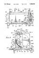
- FIG. 1is a side elevational view of a metallic, multi-wall tank assembly with accessible tank and dispenser means and drain system;
- FIG. 1ais a vertical section showing equipment used with the tank assembly
- FIG. 2is a vertical section taken on lines 2--2 of FIG. 1;
- FIG. 2ashows a modified tank assembly similar to FIG. 1a
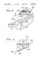
- FIG. 3is a perspective view showing a dispenser support and drain means
- FIG. 4is a section taken on lines 4--4 of FIG. 3;
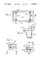
- FIG. 5is a top plan view of a receptacle unit for supporting the multi-wall tank assembly of FIG. 1;
- FIG. 6is an enlarged section taken on lines 6--6 of FIG. 5;
- FIG. 7is an enlarged plan view of a tank support assembly
- FIG. 8is an elevation taken on lines 8--8 of FIG. 7;
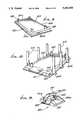
- FIG. 9is a perspective view of a modified, all-metal berm structure
- FIG. 10is a perspective view of a further modified berm structure, with crash poles
- FIG. 11is an enlarged section taken through a berm structure like that of FIG. 10 showing crash pole support;
- FIG. 12is an enlarged section like FIG. 11 but showing berm bottom plate removable attachment to a foundation;
- FIG. 13is a vertical section taken through a modified double hull tank assembly, with external and internal ducting, the tank supported on a berm;
- FIG. 14is a view like FIG. 13 but showing a single, metal wall tank with outwardly exposed fireproofing material
- FIG. 15is a vertical elevation, taken in endwise section, showing a tank assembly with dispenser at one end;
- FIG. 16is a view like FIG. 15 showing a modified dispensing system
- FIG. 17is a perspective view showing an enclosed tank assembly with end dispenser, as in FIG. 15;
- FIG. 18is a view like FIG. 17 showing a similar enclosed tank assembly with top and side dispenser.
- FIG. 19is a perspective view showing a spill containment compartment.
- FIGS. 1 and 2show a tank assembly 10 having lightweight wall means defining inner wall means 11, and outer wall means 12.
- the inner wall means 11typically forms an inner cylindrical tank 111 having a cylindrical side wall 11a, top wall 11b, bottom wall 11c, and upright end walls 11d and 11e.
- Inner tank interioris formed at 11f for containing liquid hydrocarbon indicated at 13, or hydrocarbons, or the like.
- Vehicle fuelsuch as gasoline or diesel fuel, are examples.
- the outer wall means 12typically forms an outer tank 112 having side walls 12a, top wall 12b, bottom wall 12c, and end walls 12d and 12e whereby the primary enclosed space 17 is formed between the two tanks, and surrounds the inner tank.
- the walls of the two tanksmay consist of steel and be less than one inch thick, for lightweight tank construction enhancing portability, for installation above ground at different sites, as desired. Glass fiber walls, or reinforced walls, resin impregnated, are also contemplated. Typically, steel walls are used and are about 10 gauge (1/8 to 1/4 inch thick) The tank length may typically be from 4 to 50 feet. The overall tank wall thickness may be about two inches to be bullet (large caliber) resistant.
- thermal barrier material 117is injected, as via a nozzle, or otherwise applied into spaces 17a, 17b and above 17b; and if such material is expansible, it may expand therein as foam, filling such space 17 or spaces.
- Usable thermal barrier materialsinclude foamed concrete, VERMICULITE, styrofoam, urethane foam, pumice, FENDOLITE, and the like.
- an additional thermal barriersuch as fire resistant material in a thin (less than 1/4 inch) layer 23, is applied to the outer surface of the inner tank 11.
- FENDOLITEconsisting of a mixture of VERMICULITE and Portland cement.
- VERMICULITEis hydrate aluminum-iron magnesium silicate; it is incombustible, and is lightweight.
- Portland cementis of well-known composition.
- the top wall 12b of the outer tankincludes a horizontal sub-wall 12b-1, and two opposite downwardly and sidewardly tapering sub-walls 12b-2 and 12b-3.
- Equipment located at the top of the tank assemblyis as shown, and includes
- auxiliary ports 82accessing inner space 11f, with protective (brick) plate attached to 11c protecting 11c from damage by rods or sticks inserted via 82,
- vapor recovery port 83accessing 11f, fluid product fill port 84 and duct 84a extending into the lower interior of space 11f, duct 84a being stabilized from excessive movement by support 84a' attached to 11c,
- leak monitor port 87via which fluid leaking into open (unfilled) space 17 may be monitored, i.e., detected, as by an electronic sensor, or manula gauging,
- product extraction port 81accessing the lower interior of the inner tank space 11f through inlet opening 81a' of upright product extraction duct 81a. The latter is stabilized against excessive motion by support 81a",
- a liquid product delivery line 81bmay be installed in space 17 to provide fire protection and leak containment. Fittings 81b" in space 17 stabilize 81b against movement.
- Space 32may contain, or be filled, with a non-oxidizable inert gas, such as N 2 , for enhanced protection in case of leakage of hydrocarbon into the space.
- a non-oxidizable inert gassuch as N 2
- the assembly, as described,provides protection for the hydrocarbon contents such that up to 2,000° F. flame applied for a considerable period of time (1 to 2 hours) to the outer tank will not result in heating of the hydrocarbon contents in space 31 dangerously above ambient temperature (for example about 10% of above ambient in certain cases.
- FIGS. 1, 1a and 2show the provision of a 18 product delivery duct 84 having an entrance at 84a' accessing fuel in the lower interior of space 11f within the inner tank, facilitating delivery of fuel into the tank, after lifting of an access door 91 at wall 12b-2. See door hinge 91a.
- a monitoring port 87, upon recovery port 83, and overfill container fluid drain back port 85,are also thus accessible. See line 90a connecting port 90 with the lower interior space 17a below the inner tank.
- Fuelmay also be filled into the tank 11 via auxiliary fill duct 93 in space 88 below the lifted door 90, connecting to fill duct 84a, capped at 84. Spillage resulting from such filling is conducted via the inclined wall 95 at the bottom of space 88 to the tank interior 11f, as via a suitable port at 85.
- FIG. 1, 1a, 3 and 4show the provision of a product dispenser 87, including vertically elongated pump unit 187, intake duct 188 from tank 11 via lines 81a and 81b to unit 187, and dispenser hose 189 with nozzle 191.
- the lattermay be vertically releasably supported by unit 187, at 192, as shown.
- Hose 189is retracted by retracting assembly 96, to protect the hose from damage.
- Structureis provided adjacent the end wall 12e to support the dispenser 87.
- platform unit 200projecting sidewardly adjacent a lower portion of wall 12e for supporting the dispenser unit adjacent to the end of tank 12 at wall 12e, enabling ease of fuel dispensing; in addition any spillage from the unit 187 drains into drain or platform unit 200a of structure 200, and then downwardly and laterally to fall into collection space 201 in receptacle 202. See drainage arrows 203, as in FIGS. 3 and 4.
- FIG. 2ashows a tank assembly somewhat similar to FIG. 1a, and with corresponding elements bearing the same numbers.
- FIGS. 3 and 4show the platform unit 200 as including a top plate 205 to anchor the dispenser unit (see bolt holes 206), and also to drain fuel spillage as via a central opening 207. Draining fuel falls onto lower inclined plate 208, and then drains at 203. See also side plates 209 interconnecting plates 205 and 208. Liquid containing ledge 210 bounds the plate 205.
- Receptacle 202includes a concrete slab 211 having a rectangular concrete dike or berm 212 bounding the collection space 201, extending under the entirety of the tank assembly 10.
- Anchor legs 213 integral with slab 211project into the earth and act as supports.
- I-beams 216support the tank assembly 10 on the upper surface of the slab, as shown.
- Fire extinguishing material(such as water or CO 2 ) may be released from nozzle 250 spaced along the berm and supplied via manifold 251 in the berm, storage bottle 252 and emergency valve 253.
- FIGS. 5 to 8show anchor structure to anchor the beams 216 to the slab. See shackle 217 bolted at 218 to the slab, and to which the beam is bolted at 219. See drain 310 in berm wall 212a. Anchor plates ar provided at 220. Seismic stability is thereby achieved.
- Fire-resistant materialmay, if desired, be sprayed via a nozzle onto the outermost tank walls to form a first layer 250a which is allowed to harden or cure in situ, covering all such walls. Then, if desired, a second nozzle, or the same nozzle, may be employed to spray the material onto layer 250a, forming a second layer 250b, also allowed to harden in situ, covering all outer walls or layers 250a.
- the combination of thus formed fire resistant sub-shellsform a composite shell, leak resistant, fire resistant, and projectile resistant, typically having a thickness between 1/4 inch and 1 inch, and which chars when heated to elevated temperatures (1,000° F. to 2,000° F.) as by intense flames.
- a wire meshmay be applied between such layers or shells 250a and 250b for strengthening purposes.
- the application of fire-resistant materialis preferably such as to coat the top wall 12b at the top of the assembly, and the supports 216 under the outer tank bottom wall 12c, as shown.
- Such materialsare disclosed in Ser. Nos. 331,548 and 509,142 referred to above, and incorporated herein by reference.
- FIG. 9shows a transportable berm structure, including metallic plate structure, extending horizontally to support a tank assembly, as described, and to be described. See in this regard horizontal, rectangular plate 300, which may consist of steel.
- a metallic berm 301is mounted on that plate, and extends in a rectangular loop, having berm side stretches 301a and 301b, and berm end stretches 301c and 301d.
- Each berm stretchmay have a cross section, as indicated in FIG. 11, with spaced, parallel, upright plates 302 and 303 welded at 302a and 303a to plate 300, and a top plate 304 covering the enclosed space or tunnel 305.
- a tank assembly 315is typically supported on plate 300, inwardly of the berm, and on I-beam supports 308, as indicated. Note in FIG. 9 corner L-shaped brackets 309 of steel and extending upright to confine and center the tank.
- FIG. 10The construction shown in FIG. 10 is generally the same as in FIG. 9; however, upright steel crash poles 310 are added, and positioned outside the berm to receive and absorb crash loads (see arrow L in FIG. 11) as from exterior vehicles, thereby protecting the tank against impact.
- FIG. 11shows the pole 310 as supported at its lower end 310a on a plate extension 300b, as are all poles as seen in FIG. 10.
- a steel reinforcement strut 312may be attached at one vertical edge to the pole (see weld connection 313) and may be attached at an opposite vertical edge to the berm 301 (see weld connection 314).
- the tank assemblyis generally indicated at 315, spaced inwardly from, and protected by the berm and/or pole.
- the bermperforms multiple functions, i.e., it contains tank drainage at 299 on plate 300; it protects and carries auxiliary equipment such as piping and cabling, as described; it laterally supports or reinforces the crash pole; and it acts with the pole to absorb lateral crash loads L, the wall 302 and 303 being able to laterally flex (see flexed positions 302b and 303b) in order to absorb side loading. Also, the entire unit or assembly is transportable from one point of tank installation to another, and separately from the tank, for performance of its multiple functions.
- FIG. 12shows a means to releasably attach the metallic plate 300 to a foundation, such as concrete or asphalt pad 320.
- auxiliary plate means 321is attached, as by a fastener 322, to the pad, the plate means overlapping the portions 300d of the plate 300 protruding outwardly beyond the berm 301.
- plate means 321includes a lower plate 321a seating on the pad, and an upper plate 321b overlapping the main plate 300 at 326. Plates 321a and 321b are weld connected at 327.
- a fire-resistant tank assembly 330has wall means defining an interior storage space 331 for flammable liquid 332.
- the wall meansincludes a first metallic, cylindrical wall 333 extending generally longitudinally; and a second metallic, cylindrical wall 334 also extending generally horizontally and concentrically about wall 333.
- Fire-resistant material 335 of one or more of the types referred to abovesubstantially fills the space 336 between the two metal walls, that space typically being about two inches thick, but can be up to six inches thick.
- the outer tankis supported on the plate 300, as by supports 337. End walls 333a and 334a close opposite ends of the cylindrical walls 333 and 334; and spaces between walls 333a and 334a are also filled with fire-resistant material. See similar space in FIG. 1a for example, between tank end walls.
- inner and outer tanksare provided.
- Means to fill liquid into the tank and/or dispense liquid from the tank interior 331includes an interior duct 340 extending vertically within the interior to have a port 340a near the bottom of interior 331.
- Duct 340extends up through the tops of the tanks, and connects to an exterior duct 342 having a horizontal stretch 342a, and a downcomer stretch 342b, with a fill or dispenser port 342c provided by a coupling.
- the exterior ductmay be installed, and be covered with fire-resistant material 335a.
- the liquid in the FIG. 13 tanktypically undergoes less than a 40° F. temperature increase in a 2,000° F. pool fire, over two hours.
- the tank construction seen in FIG. 14is the same as that of FIG. 13 except that the outer metal tank wall 334 (and associated end walls) is omitted.
- the inner metallic wall 333closed at its opposite ends, is entirely covered with fire-resistant material 335 (about two inches thick), as is the external duct structure 342.
- a metallic housing 350surrounds the inner tank 333, as is also seen in FIGS. 17 and 18. See dispenser pump box 351 at the top of duct 342', externally of the tank 333 and housing 350, as in FIG. 18. Liquid in the FIG. 14 tank structure undergoes less than 100° F. temperature rise in two hours in a 2,000° F. pool fire.
- a flexible dispensing lineextends at 352 from the pump box 351 to a dispenser nozzle 354 supported on a hanger 355 on the housing side wall.
- the external duct 342is connected to a dispenser pump unit 356 supported on a shelf 357 at one end 358 of the housing. See also delivery line 359 and nozzle 360.
- Tank supportsare seen at 361, and are sized to seat on the steel plate 300 referred to above.
- a single shell, cylindrical storage tank 333'is covered with fire-resistant material 335' (about two inches thick).
- An outer metallic housing 350'surrounds the storage tank.
- a pump dispenser 390is supported on a shelf 391 at one end 362 of the outer housing.
- Internal dispenser/fill duct 363extends vertically in the tank 333', and has a discharge/inlet port at 364 near the bottom of the tank interior.
- Duct 363connects with an external duct 365 that protrudes at the exterior of the housing 350' at 365a.
- a control valve 366is connected into duct length 365a.
- Duct 365then extends downwardly at 365b in the space 367 between 333' and 350', at one end of the latter, as shown.
- Duct length 365bconnects to a line 370 running beneath shelf 391 to the dispenser 390.
- a dispenser nozzle 372connects to a delivery line 373 from the dispenser.
- FIG. 16the structure is like that in FIG. 15 except that duct 365 is entirely within the space 367 between 333' and 350', that space filled with fire-resistant material.
- a box or container 380is shaped to fit into the top of the housing 350, as is indicated in FIGS. 17 and 18. That box has a lid 381, hinged at 381a to be elevated, giving access to the box interior.
- a flammable liquid fill port 382is provided in the box interior and is capped at 382a. Spillage is contained in the box and drains to the tank 333 interior, via a drain at 384.
- a sight gaugeis also provided at 385.
- FIG. 2ais a schematic showing of a multiple tank assembly, with multiple ports as labeled, the assembly being similar to the FIG. 1a assembly.
Landscapes
- Engineering & Computer Science (AREA)
- Mechanical Engineering (AREA)
- General Engineering & Computer Science (AREA)
- Physics & Mathematics (AREA)
- Thermal Sciences (AREA)
- Life Sciences & Earth Sciences (AREA)
- Wood Science & Technology (AREA)
- Filling Or Discharging Of Gas Storage Vessels (AREA)
Abstract
Description
Claims (16)
Priority Applications (1)
| Application Number | Priority Date | Filing Date | Title |
|---|---|---|---|
| US07/803,612US5285920A (en) | 1989-03-31 | 1991-12-09 | Fire resistant tank assembly and liquid hydrocarbon dispensing |
Applications Claiming Priority (3)
| Application Number | Priority Date | Filing Date | Title |
|---|---|---|---|
| US07/331,548US5012949A (en) | 1989-03-31 | 1989-03-31 | Fire resistant tank construction |
| US07/509,142US4989750A (en) | 1990-04-16 | 1990-04-16 | Fire resistant tank construction |
| US07/803,612US5285920A (en) | 1989-03-31 | 1991-12-09 | Fire resistant tank assembly and liquid hydrocarbon dispensing |
Related Parent Applications (1)
| Application Number | Title | Priority Date | Filing Date |
|---|---|---|---|
| US07/509,142Continuation-In-PartUS4989750A (en) | 1989-03-31 | 1990-04-16 | Fire resistant tank construction |
Publications (1)
| Publication Number | Publication Date |
|---|---|
| US5285920Atrue US5285920A (en) | 1994-02-15 |
Family
ID=27406805
Family Applications (1)
| Application Number | Title | Priority Date | Filing Date |
|---|---|---|---|
| US07/803,612Expired - Fee RelatedUS5285920A (en) | 1989-03-31 | 1991-12-09 | Fire resistant tank assembly and liquid hydrocarbon dispensing |
Country Status (1)
| Country | Link |
|---|---|
| US (1) | US5285920A (en) |
Cited By (8)
| Publication number | Priority date | Publication date | Assignee | Title |
|---|---|---|---|---|
| US5533648A (en)* | 1994-01-10 | 1996-07-09 | Novus International, Inc. | Portable storage and dispensing system |
| US6257437B1 (en) | 1998-12-17 | 2001-07-10 | Electus P. Slater | Above ground storage tank for holding combustible material and supporting equipment thereon |
| WO2000035779A3 (en)* | 1998-12-17 | 2001-10-18 | Electus P Slater | Above ground storage tank for holding combustible material and supporting equipment thereon |
| US20050115621A1 (en)* | 2003-11-07 | 2005-06-02 | Van Vliet Maury G. | Mobile dual containment highway tank |
| US20070278248A1 (en)* | 2006-05-31 | 2007-12-06 | Van Vliet Scott M | Self-contained remote fueling system |
| FR3018788A1 (en)* | 2014-03-24 | 2015-09-25 | Prot Incendie Soc Ind De | CONTAINER FOR STORAGE OF HAZARDOUS PRODUCTS |
| US10850971B1 (en)* | 2019-10-08 | 2020-12-01 | Cafu App Dmcc | Mobile fuel dispenser |
| KR102313236B1 (en)* | 2021-04-01 | 2021-10-14 | (주)대현기공 | Pressure Vessel Storing LNG |
Citations (40)
| Publication number | Priority date | Publication date | Assignee | Title |
|---|---|---|---|---|
| US810237A (en)* | 1905-05-06 | 1906-01-16 | William B Wadsworth | Means for controlling the level of liquids. |
| US1114019A (en)* | 1911-09-09 | 1914-10-20 | Sf Bowser & Co Inc | Automatic valve. |
| US1273195A (en)* | 1917-07-17 | 1918-07-23 | Harrison B Snyder | Fluid-control apparatus. |
| US1625765A (en)* | 1926-05-10 | 1927-04-19 | Cresco Creamery Supply Co | Valved outlet for pasteurizers |
| US1724582A (en)* | 1927-12-31 | 1929-08-13 | William E Hart | Liquid-fuel-elevating device for motor vehicles |
| US2460054A (en)* | 1945-11-26 | 1949-01-25 | John H Wiggins | Tank bottoms equipped with improved means for testing seams and recovering leakage from same |
| US2558694A (en)* | 1949-08-26 | 1951-06-26 | Karl M Speig | Storage tank |
| US2772834A (en)* | 1952-10-22 | 1956-12-04 | Otto Wanek | Steam turbine operated centrifugal pump mechanisms |
| US2858136A (en)* | 1954-02-23 | 1958-10-28 | Air Reduction | Transport container for liquefied gases |
| US2860807A (en)* | 1954-03-30 | 1958-11-18 | Admiral Corp | Refrigerator cabinet |
| US2864527A (en)* | 1956-12-10 | 1958-12-16 | Herrick L Johnston Inc | Container for liquefied gas |
| US2869751A (en)* | 1954-09-03 | 1959-01-20 | Pfauder Permutit Inc | Insulated storage tank and method of making a storage tank |
| US2931211A (en)* | 1953-11-18 | 1960-04-05 | Babcock & Wilcox Co | Storage tank exposure protection covering |
| US3595424A (en)* | 1969-02-24 | 1971-07-27 | Conch Int Methane Ltd | Containers for liquefied gases |
| US3666132A (en)* | 1970-01-14 | 1972-05-30 | Bridgestone Liquified Gas Co L | Membrane container construction for storing low-temperature liquified gas |
| US3702592A (en)* | 1970-11-18 | 1972-11-14 | American Air Filter Co | Fire retardant container |
| US3827455A (en)* | 1973-09-06 | 1974-08-06 | Dow Chemical Co | Self-sealing system for storing and dispensing a fluid material |
| US3941272A (en)* | 1974-03-27 | 1976-03-02 | Kaiser Aluminum & Chemical Corporation | Cryogenic transport |
| US3952907A (en)* | 1973-11-24 | 1976-04-27 | British Industrial Plastics Limited | Liquid storage installations |
| US3967256A (en)* | 1973-04-26 | 1976-06-29 | Marine And Industrial Developments Limited | Integrity monitoring system for storage tank insulation |
| US3969563A (en)* | 1969-08-28 | 1976-07-13 | Hollis Sr Russell E | Protective wall structure |
| US3989862A (en)* | 1970-10-13 | 1976-11-02 | Jones & Laughlin Steel Corporation | Method and apparatus for vapor-depositing coatings on substrates |
| US4069075A (en)* | 1974-03-25 | 1978-01-17 | Avco Corporation | Structural support for char derived from intumescent coatings |
| US4376489A (en)* | 1981-02-23 | 1983-03-15 | Bethlehem Steel Corporation | Container for hazardous material |
| US4469129A (en)* | 1980-08-04 | 1984-09-04 | Dixon John W | Above ground gasoline storage apparatus |
| US4493945A (en)* | 1982-08-23 | 1985-01-15 | Thermal Science, Inc. | Thermal protective system |
| US4651893A (en)* | 1985-03-21 | 1987-03-24 | Mooney Joseph R | Liquid storage tank assembly |
| US4685327A (en)* | 1983-10-21 | 1987-08-11 | Sharp Bruce R | Total containment storage tank system |
| US4697618A (en)* | 1985-01-07 | 1987-10-06 | The American Tank & Fabricating Co. | Container structure for dangerous material |
| US4815621A (en)* | 1987-12-18 | 1989-03-28 | Bartis Peter A | Above-ground portable storage tank |
| US4826644A (en)* | 1986-12-01 | 1989-05-02 | Convault, Inc. | Method for entombment of tanks in concrete |
| US4844287A (en)* | 1987-11-13 | 1989-07-04 | Long Delmar D | Leak containment system for underground storage tanks |
| US4890983A (en)* | 1988-08-17 | 1990-01-02 | Pacific Environmental Industries | Above-ground storage system |
| US4893397A (en)* | 1986-11-27 | 1990-01-16 | Micropore International Limited | Fire-resistant container and method of assembling same |
| US4989750A (en)* | 1990-04-16 | 1991-02-05 | Lrs, Inc. | Fire resistant tank construction |
| US5004632A (en)* | 1988-03-31 | 1991-04-02 | Lrs, Inc. | Fire resistant tank construction |
| US5005615A (en)* | 1990-01-08 | 1991-04-09 | Lrs, Inc. | Safety tank apparatus for liquid storage |
| US5012949A (en)* | 1989-03-31 | 1991-05-07 | Lrs, Inc. | Fire resistant tank construction |
| US5016689A (en)* | 1990-01-08 | 1991-05-21 | Lrs, Inc. | Safety tank apparatus for liquid storage |
| US5038456A (en)* | 1990-04-26 | 1991-08-13 | Lrs, Inc. | Fire resistant tank construction method |
- 1991
- 1991-12-09USUS07/803,612patent/US5285920A/ennot_activeExpired - Fee Related
Patent Citations (40)
| Publication number | Priority date | Publication date | Assignee | Title |
|---|---|---|---|---|
| US810237A (en)* | 1905-05-06 | 1906-01-16 | William B Wadsworth | Means for controlling the level of liquids. |
| US1114019A (en)* | 1911-09-09 | 1914-10-20 | Sf Bowser & Co Inc | Automatic valve. |
| US1273195A (en)* | 1917-07-17 | 1918-07-23 | Harrison B Snyder | Fluid-control apparatus. |
| US1625765A (en)* | 1926-05-10 | 1927-04-19 | Cresco Creamery Supply Co | Valved outlet for pasteurizers |
| US1724582A (en)* | 1927-12-31 | 1929-08-13 | William E Hart | Liquid-fuel-elevating device for motor vehicles |
| US2460054A (en)* | 1945-11-26 | 1949-01-25 | John H Wiggins | Tank bottoms equipped with improved means for testing seams and recovering leakage from same |
| US2558694A (en)* | 1949-08-26 | 1951-06-26 | Karl M Speig | Storage tank |
| US2772834A (en)* | 1952-10-22 | 1956-12-04 | Otto Wanek | Steam turbine operated centrifugal pump mechanisms |
| US2931211A (en)* | 1953-11-18 | 1960-04-05 | Babcock & Wilcox Co | Storage tank exposure protection covering |
| US2858136A (en)* | 1954-02-23 | 1958-10-28 | Air Reduction | Transport container for liquefied gases |
| US2860807A (en)* | 1954-03-30 | 1958-11-18 | Admiral Corp | Refrigerator cabinet |
| US2869751A (en)* | 1954-09-03 | 1959-01-20 | Pfauder Permutit Inc | Insulated storage tank and method of making a storage tank |
| US2864527A (en)* | 1956-12-10 | 1958-12-16 | Herrick L Johnston Inc | Container for liquefied gas |
| US3595424A (en)* | 1969-02-24 | 1971-07-27 | Conch Int Methane Ltd | Containers for liquefied gases |
| US3969563A (en)* | 1969-08-28 | 1976-07-13 | Hollis Sr Russell E | Protective wall structure |
| US3666132A (en)* | 1970-01-14 | 1972-05-30 | Bridgestone Liquified Gas Co L | Membrane container construction for storing low-temperature liquified gas |
| US3989862A (en)* | 1970-10-13 | 1976-11-02 | Jones & Laughlin Steel Corporation | Method and apparatus for vapor-depositing coatings on substrates |
| US3702592A (en)* | 1970-11-18 | 1972-11-14 | American Air Filter Co | Fire retardant container |
| US3967256A (en)* | 1973-04-26 | 1976-06-29 | Marine And Industrial Developments Limited | Integrity monitoring system for storage tank insulation |
| US3827455A (en)* | 1973-09-06 | 1974-08-06 | Dow Chemical Co | Self-sealing system for storing and dispensing a fluid material |
| US3952907A (en)* | 1973-11-24 | 1976-04-27 | British Industrial Plastics Limited | Liquid storage installations |
| US4069075A (en)* | 1974-03-25 | 1978-01-17 | Avco Corporation | Structural support for char derived from intumescent coatings |
| US3941272A (en)* | 1974-03-27 | 1976-03-02 | Kaiser Aluminum & Chemical Corporation | Cryogenic transport |
| US4469129A (en)* | 1980-08-04 | 1984-09-04 | Dixon John W | Above ground gasoline storage apparatus |
| US4376489A (en)* | 1981-02-23 | 1983-03-15 | Bethlehem Steel Corporation | Container for hazardous material |
| US4493945A (en)* | 1982-08-23 | 1985-01-15 | Thermal Science, Inc. | Thermal protective system |
| US4685327A (en)* | 1983-10-21 | 1987-08-11 | Sharp Bruce R | Total containment storage tank system |
| US4697618A (en)* | 1985-01-07 | 1987-10-06 | The American Tank & Fabricating Co. | Container structure for dangerous material |
| US4651893A (en)* | 1985-03-21 | 1987-03-24 | Mooney Joseph R | Liquid storage tank assembly |
| US4893397A (en)* | 1986-11-27 | 1990-01-16 | Micropore International Limited | Fire-resistant container and method of assembling same |
| US4826644A (en)* | 1986-12-01 | 1989-05-02 | Convault, Inc. | Method for entombment of tanks in concrete |
| US4844287A (en)* | 1987-11-13 | 1989-07-04 | Long Delmar D | Leak containment system for underground storage tanks |
| US4815621A (en)* | 1987-12-18 | 1989-03-28 | Bartis Peter A | Above-ground portable storage tank |
| US5004632A (en)* | 1988-03-31 | 1991-04-02 | Lrs, Inc. | Fire resistant tank construction |
| US4890983A (en)* | 1988-08-17 | 1990-01-02 | Pacific Environmental Industries | Above-ground storage system |
| US5012949A (en)* | 1989-03-31 | 1991-05-07 | Lrs, Inc. | Fire resistant tank construction |
| US5005615A (en)* | 1990-01-08 | 1991-04-09 | Lrs, Inc. | Safety tank apparatus for liquid storage |
| US5016689A (en)* | 1990-01-08 | 1991-05-21 | Lrs, Inc. | Safety tank apparatus for liquid storage |
| US4989750A (en)* | 1990-04-16 | 1991-02-05 | Lrs, Inc. | Fire resistant tank construction |
| US5038456A (en)* | 1990-04-26 | 1991-08-13 | Lrs, Inc. | Fire resistant tank construction method |
Non-Patent Citations (23)
| Title |
|---|
| "1/2" Waste Oil Evacuation System (drawing dated Mar. 15, 1987). |
| "Aro Air Operated Diaphragm Pumps", (1986). |
| "Aro Lubrication Equipment" (1989), pp. 31 and 33. |
| "Oil Evacuation System", Aro Corp., (1982). |
| Agape Tank Sales materials (dated by postmark Jun. 7, 1989).* |
| Aro Air Operated Diaphragm Pumps , (1986).* |
| Aro Lubrication Equipment (1989), pp. 31 and 33.* |
| Brochure Underwriters Laboratory Listed Tank , Air Boy Sales & Manufacturing Company.* |
| Brochure--"Underwriters Laboratory Listed Tank", Air Boy Sales & Manufacturing Company. |
| Cla Val Co. float control parts list (1977).* |
| Cla-Val Co. float control parts list (1977). |
| Doehrman, Inc. facsimile dated May 9, 1989.* |
| Doehrman, Inc.--facsimile dated May 9, 1989. |
| Husky 1030 Double Diaphragm Pump (1987) instructions and parts list.* |
| Internal Search Report PCT/US90/01654, Mar. 28, 1990.* |
| Oil Evacuation System , Aro Corp., (1982).* |
| Reliance Tank Sales Materials (undated) price list date Jan. 20, 1989.* |
| Reliance Tank Sales Materials (undated)--price list date Jan. 20, 1989. |
| Safe T Tank Corp. sales materials dated 1987 Sales materials from Air Boy (Jun. 1988) advertisement dated Feb. 1987 from Keesee, Lube Cube sales materials dated Jul. 1, 1988.* |
| Safe-T-Tank Corp. sales materials dated 1987-Sales materials from Air Boy (Jun. 1988)--advertisement dated Feb. 1987 from Keesee, "Lube Cube" sales materials dated Jul. 1, 1988. |
| UL 142 Standard for Safety, Steel Aboveground Tanks (1987).* |
| Uniform Fire Code, 1985 Ed., pp. 203 278.* |
| Uniform Fire Code, 1985 Ed., pp. 203-278. |
Cited By (10)
| Publication number | Priority date | Publication date | Assignee | Title |
|---|---|---|---|---|
| US5533648A (en)* | 1994-01-10 | 1996-07-09 | Novus International, Inc. | Portable storage and dispensing system |
| AU687071B2 (en)* | 1994-01-10 | 1998-02-19 | Novus International Inc | Portable storage and dispensing system |
| US6257437B1 (en) | 1998-12-17 | 2001-07-10 | Electus P. Slater | Above ground storage tank for holding combustible material and supporting equipment thereon |
| WO2000035779A3 (en)* | 1998-12-17 | 2001-10-18 | Electus P Slater | Above ground storage tank for holding combustible material and supporting equipment thereon |
| US6349873B1 (en) | 1998-12-17 | 2002-02-26 | Electus P. Slater | Above ground storage tank for holding combustible material and supporting equipment thereon |
| US20050115621A1 (en)* | 2003-11-07 | 2005-06-02 | Van Vliet Maury G. | Mobile dual containment highway tank |
| US20070278248A1 (en)* | 2006-05-31 | 2007-12-06 | Van Vliet Scott M | Self-contained remote fueling system |
| FR3018788A1 (en)* | 2014-03-24 | 2015-09-25 | Prot Incendie Soc Ind De | CONTAINER FOR STORAGE OF HAZARDOUS PRODUCTS |
| US10850971B1 (en)* | 2019-10-08 | 2020-12-01 | Cafu App Dmcc | Mobile fuel dispenser |
| KR102313236B1 (en)* | 2021-04-01 | 2021-10-14 | (주)대현기공 | Pressure Vessel Storing LNG |
Similar Documents
| Publication | Publication Date | Title |
|---|---|---|
| US5103996A (en) | Fire resistant tank construction | |
| US5038456A (en) | Fire resistant tank construction method | |
| US4989750A (en) | Fire resistant tank construction | |
| US4041722A (en) | Impact resistant tank for cryogenic fluids | |
| US5082138A (en) | Fire resistant tank construction | |
| US5081761A (en) | Double wall steel tank | |
| US5092024A (en) | Fire resistant tank construction method | |
| RU2404106C2 (en) | Safe and ecofriendly underground storage tank for oil products | |
| DK2241485T3 (en) | The anti-explosive and environment protecting oil (gas) -påfyldningsindretning | |
| US5251473A (en) | Method and storage tank system for aboveground storage of flammable liquids | |
| US5012949A (en) | Fire resistant tank construction | |
| US4934553A (en) | Above ground waste tank | |
| US5285920A (en) | Fire resistant tank assembly and liquid hydrocarbon dispensing | |
| JPH03226483A (en) | Device for receiving secondary liquid therein | |
| US6644165B1 (en) | Explosion containment vessel | |
| JPS58196395A (en) | Storage tank | |
| US5004632A (en) | Fire resistant tank construction | |
| NL8004530A (en) | DOUBLE WALL BARREL FOR DEEP-COOLED LIQUID. | |
| US6286707B1 (en) | Container for above-ground storage | |
| NO754413L (en) | ||
| CA1116877A (en) | Subterranean storage of liquids | |
| US5450978A (en) | Environment compatible storage vessel | |
| US5562162A (en) | Portable fueling facility | |
| EP0624752A1 (en) | Protective container with a fluid-tight seal for the underground installation of tanks containing pressurised liquefied gas | |
| KR102123102B1 (en) | Container ship |
Legal Events
| Date | Code | Title | Description |
|---|---|---|---|
| AS | Assignment | Owner name:LRS, INC.,, CALIFORNIA Free format text:ASSIGNMENT OF ASSIGNORS INTEREST.;ASSIGNOR:MCGARVEY, DAVID C.;REEL/FRAME:005948/0936 Effective date:19911126 | |
| AS | Assignment | Owner name:HOOVER CONTAINMENT SYSTEMS, INC., MARYLAND Free format text:ASSIGNMENT OF ASSIGNORS INTEREST;ASSIGNOR:LRS, INC.;REEL/FRAME:007095/0585 Effective date:19940831 | |
| AS | Assignment | Owner name:FLEET CAPITAL CORPORATION, CALIFORNIA Free format text:GRANT OF SECURITY INTEREST;ASSIGNOR:HOOVER CONTAINMENT, INC.;REEL/FRAME:007773/0563 Effective date:19951027 | |
| FEPP | Fee payment procedure | Free format text:PAYOR NUMBER ASSIGNED (ORIGINAL EVENT CODE: ASPN); ENTITY STATUS OF PATENT OWNER: LARGE ENTITY | |
| AS | Assignment | Owner name:HOOVER CONTAINMENT, INC., MARYLAND Free format text:ASSIGNMENT OF ASSIGNORS INTEREST;ASSIGNOR:HOOVER CONTAINMENT SYSTEMS, INC.;REEL/FRAME:008354/0731 Effective date:19951012 | |
| FPAY | Fee payment | Year of fee payment:4 | |
| AS | Assignment | Owner name:NATIONSBANK OF TEXAS, N.A., TEXAS Free format text:SECURITY AGREEMENT;ASSIGNOR:HOOVER CONTAINMENT, INC.;REEL/FRAME:008869/0271 Effective date:19971009 | |
| AS | Assignment | Owner name:NATIONSBANK OF TEXAS, N.A., AS AGENT, TEXAS Free format text:AMENDMENT OF SECURITY AGREEMENT;ASSIGNOR:HOOVER CONTAINMENT, INC.;REEL/FRAME:009289/0105 Effective date:19980323 | |
| AS | Assignment | Owner name:CANADIAN IMPERIAL BANK OF COMMERCE, AS ADMINISTRAT Free format text:NOTICE OF SECURITY INTEREST IN PATENTS;ASSIGNOR:CONTAINMENT SOLUTION, INC. (SUCCESSOR BY MERGER TO HOOVER CONTAINMENT, INC.);REEL/FRAME:009935/0054 Effective date:19990112 Owner name:CONTAINMENT SOLUTIONS, INC. (SUCCESSOR BY MERGER T Free format text:RELEASE BY SECURED PARTY;ASSIGNOR:NATIONS BANK, N.A (SUCCESSOR BY MERGER TO NATIONSBANK OF TEXAS, N.A.);REEL/FRAME:009935/0035 Effective date:19990112 | |
| FEPP | Fee payment procedure | Free format text:PAYER NUMBER DE-ASSIGNED (ORIGINAL EVENT CODE: RMPN); ENTITY STATUS OF PATENT OWNER: LARGE ENTITY Free format text:PAYOR NUMBER ASSIGNED (ORIGINAL EVENT CODE: ASPN); ENTITY STATUS OF PATENT OWNER: LARGE ENTITY | |
| FEPP | Fee payment procedure | Free format text:PAT HLDR NO LONGER CLAIMS SMALL ENT STAT AS SMALL BUSINESS (ORIGINAL EVENT CODE: LSM2); ENTITY STATUS OF PATENT OWNER: LARGE ENTITY | |
| REFU | Refund | Free format text:REFUND - PAYMENT OF MAINTENANCE FEE, 8TH YR, SMALL ENTITY (ORIGINAL EVENT CODE: R284); ENTITY STATUS OF PATENT OWNER: LARGE ENTITY | |
| FPAY | Fee payment | Year of fee payment:8 | |
| AS | Assignment | Owner name:STATE STREET BANK AND TRUST COMPANY, MASSACHUSETTS Free format text:ASSIGNMENT OF ASSIGNORS INTEREST;ASSIGNOR:ING (U.S.) CAPITAL LLC;REEL/FRAME:013475/0005 Effective date:20020614 | |
| AS | Assignment | Owner name:PATRIARCH PARTNERS AGENCY SERVICE, LLC, NORTH CARO Free format text:ASSIGNMENT OF ASSIGNORS INTEREST;ASSIGNOR:STATE STREET BANK AND TRUST COMPANY;REEL/FRAME:015942/0625 Effective date:20030930 | |
| AS | Assignment | Owner name:CONTAINMENT SOLUTIONS, INC. (SUCCESSOR BY MERGER T Free format text:RELEASE OF PATENT SECURITY INTEREST;ASSIGNOR:FLEET CAPITAL CORPORATION (F/K/A SHAWMUT CAPITAL CORPORATION);REEL/FRAME:014926/0543 Effective date:20040719 | |
| AS | Assignment | Owner name:PATRIARCH PARTNERS AGENCY SERVICES,LLC, NORTH CARO Free format text:SECURITY AGREEMENT;ASSIGNORS:DENALI INCORPORATED;CONTAINMENT SOLUTIONS, INC.;REEL/FRAME:016500/0802 Effective date:20021210 | |
| AS | Assignment | Owner name:HALL PATENT GROUP, LLC, TEXAS Free format text:ASSIGNMENT OF ASSIGNORS INTEREST;ASSIGNOR:CONTAINMENT SOLUTIONS, INC.;REEL/FRAME:016127/0792 Effective date:20050608 | |
| REMI | Maintenance fee reminder mailed | ||
| LAPS | Lapse for failure to pay maintenance fees | ||
| STCH | Information on status: patent discontinuation | Free format text:PATENT EXPIRED DUE TO NONPAYMENT OF MAINTENANCE FEES UNDER 37 CFR 1.362 | |
| FP | Lapsed due to failure to pay maintenance fee | Effective date:20060215 | |
| AS | Assignment | Owner name:DENALI INCORPORATED, TEXAS Free format text:RELEASE OF SECURITY INTEREST IN PATENTS AS RECORDED ON 05/02/2005 AT REEL 016500, FRAME 0802;ASSIGNOR:PATRIARCH PARTNERS AGENCY SERVICES, LLC;REEL/FRAME:018606/0565 Effective date:20061130 Owner name:CONTAINMENT SOLUTIONS, INC., TEXAS Free format text:RELEASE OF SECURITY INTEREST IN PATENTS AS RECORDED ON 05/02/2005 AT REEL 016500, FRAME 0802;ASSIGNOR:PATRIARCH PARTNERS AGENCY SERVICES, LLC;REEL/FRAME:018606/0565 Effective date:20061130 | |
| AS | Assignment | Owner name:PATRIARCH PARTNERS AGENCY SERVICES, LLC, NEW YORK Free format text:SECURITY AGREEMENT;ASSIGNOR:CONTAINMENT SOLUTIONS, INC.;REEL/FRAME:026630/0570 Effective date:20090305 |