US5285918A - Videocassette shipping container - Google Patents
Videocassette shipping containerDownload PDFInfo
- Publication number
- US5285918A US5285918AUS07/988,894US98889492AUS5285918AUS 5285918 AUS5285918 AUS 5285918AUS 98889492 AUS98889492 AUS 98889492AUS 5285918 AUS5285918 AUS 5285918A
- Authority
- US
- United States
- Prior art keywords
- lid
- base
- container
- tang
- locking
- Prior art date
- Legal status (The legal status is an assumption and is not a legal conclusion. Google has not performed a legal analysis and makes no representation as to the accuracy of the status listed.)
- Expired - Lifetime
Links
Images


Classifications
- G—PHYSICS
- G11—INFORMATION STORAGE
- G11B—INFORMATION STORAGE BASED ON RELATIVE MOVEMENT BETWEEN RECORD CARRIER AND TRANSDUCER
- G11B23/00—Record carriers not specific to the method of recording or reproducing; Accessories, e.g. containers, specially adapted for co-operation with the recording or reproducing apparatus ; Intermediate mediums; Apparatus or processes specially adapted for their manufacture
- G11B23/02—Containers; Storing means both adapted to cooperate with the recording or reproducing means
- G11B23/023—Containers for magazines or cassettes
- G11B23/0233—Containers for a single cassette
- B—PERFORMING OPERATIONS; TRANSPORTING
- B65—CONVEYING; PACKING; STORING; HANDLING THIN OR FILAMENTARY MATERIAL
- B65D—CONTAINERS FOR STORAGE OR TRANSPORT OF ARTICLES OR MATERIALS, e.g. BAGS, BARRELS, BOTTLES, BOXES, CANS, CARTONS, CRATES, DRUMS, JARS, TANKS, HOPPERS, FORWARDING CONTAINERS; ACCESSORIES, CLOSURES, OR FITTINGS THEREFOR; PACKAGING ELEMENTS; PACKAGES
- B65D55/00—Accessories for container closures not otherwise provided for
- B65D55/02—Locking devices; Means for discouraging or indicating unauthorised opening or removal of closure
- B65D55/06—Deformable or tearable wires, strings or strips; Use of seals
- Y—GENERAL TAGGING OF NEW TECHNOLOGICAL DEVELOPMENTS; GENERAL TAGGING OF CROSS-SECTIONAL TECHNOLOGIES SPANNING OVER SEVERAL SECTIONS OF THE IPC; TECHNICAL SUBJECTS COVERED BY FORMER USPC CROSS-REFERENCE ART COLLECTIONS [XRACs] AND DIGESTS
- Y10—TECHNICAL SUBJECTS COVERED BY FORMER USPC
- Y10S—TECHNICAL SUBJECTS COVERED BY FORMER USPC CROSS-REFERENCE ART COLLECTIONS [XRACs] AND DIGESTS
- Y10S206/00—Special receptacle or package
- Y10S206/807—Tamper proof
Definitions
- the inventionrelates to containers. Particularly, the invention relates to a storage container for storing and shipping a single videocassette. Specifically, the invention relates to storage and shipping containers for accepting a single videocassette which is permanently locked during shipment and becomes a usual storage container when the customer receives the cassette.
- cassettesare used primarily to record programs directly from a television for replay, or else they are purchased with a program, movie or the like pre-recorded thereon. It is desirable that these cassettes be shipped and stored in protective boxes or containers to prevent physical damage to the cassette during shipment, as well as to keep the cassette relatively dust free during storage.
- the most common type of videocassette containers/shipper used todayis the blow molded rectangular shaped plastic box of the type shown in U.S. Pat. Nos. 3,933,381 and 4,153,178.
- These types of containershave blow molded plastic base and cover portions formed of double wall construction which are hinged together for movement between open and closed positions with respect to one another.
- a latch assemblyis provided for positively locking the cover portion in a closed position.
- the latch assemblyoften includes an elongated member which slidably mounts within a trough shaped groove in the front of the cover portion.
- the cover and baseoften include formed portions which may engage with one another upon closing of the cover and which include aligned locking apertures.
- a further objective of the present inventionis to provide such a cassette storage/shipping container which is permanently locked during shipping, and which is securely latched for storage by an easily engageable snap-fit latching mechanism upon receipt by the customer.
- a still further objective of the inventionis to provide a cassette storage device which may be operated easily by the customer.
- Yet another objectiveis to provide a cassette shipper which may be manufactured by injection molding without compromising the shock dampening characteristics which a cassette shipper must have to protect an enclosed videocassette.
- Still another objective of the present inventionis to provide such a cassette storage/shipping container which has a relatively simple construction, which achieves the stated objectives in a simple, effective, and inexpensive manner, and which solves problems and satisfies needs in the art.
- the shipping container of the present inventionincluding a base having a storage compartment formed by a pair of spaced end walls and a pair of spaced side walls; a closure lid for said storage compartment; a locking aperture formed in one of the lid and base; a destructible locking tang formed in the other of the lid and base, a portion of said tang being insertable through the aperture for locking said lid and base in a closed position; and means on said locking tangs for destructively removing said tang to permit unlocking of the lid from the base.
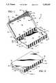
- FIG. 1is a perspective view of the improved videocassette storage/shipping container with the lid open;
- FIG. 2is a perspective view of the improved videocassette storage/shipping container as shown in FIG. 1, with the lid in a closed and locked position:
- FIG. 3is a top plan view of the improved videocassette storage/shipping container in full open position showing an enclosed videocassette in phantom;
- FIG. 4is a greatly enlarged fragmentary view of the encircled area shown on FIG. 2, in partial cut-away and in section, showing the permanently snap-fit locking arrangement for shipment as well as the releasable snap-fit connection which will be used during storage; and
- FIG. 5is a fragmentary view similar to FIG. 4 of the permanent locking tab in a partially removed position.
- Container 10has a rectangular box-shaped configuration and forms a hollow storage compartment when closed, and preferably is formed of an injection molded plastic material, such as polypropylene.
- Container 10includes a base portion 11, which has a rectangular shaped flat bottom wall 12 with upstanding parallel spaced end walls 14, with each of end walls 14 having an upper edge 16. Perpendicular to end walls 14 are spaced parallel front and rear walls, 18 and 20, respectively, having upper edges 22 and 24, respectively. End walls 14 and side walls 18 and 20 are formed integrally with bottom wall 12 and are arranged in a rectangular configuration to enclose all four sides of bottom wall 12, thereby defining the storage compartment.
- Walls 14, 18 and 20preferably are positioned along the perimeter of the bottom wall 12. Moreover, front wall 18 adjoins side walls 14 and in arcuate shaped corners 26.
- spaced apart elongated apertures 28extend through front wall 18, preferably adjacent arcuate corners 26.
- Top edges 16 and 22are provided with equally spaced, outwardly extending, semi-circular projections 30 which cooperate with similar projections to create a snap-fit engagement as will be described hereinbelow. It should be understood that any configuration of projection 30 could be employed which would create a usual snap-fit engagement without departing from the spirit of the present invention.
- Container 10further includes a lid 32 which has a rectangular box-shaped configuration and forms a hollow enclosure when closed on base portion 11, and preferably is formed of a molded plastic material, such as polypropylene.
- Lid 32includes a rectangular shaped closure wall 34 with upstanding parallel spaced apart end walls 36 and a front wall 38 having a free edge 52.
- Walls 36 and 38are formed integrally with closure wall 34 and are arranged in a U-shaped configuration to enclose three sides of wall 34.
- Walls 36 and 38preferably are positioned along the perimeter or the outer edge of closure wall 34. End walls 36 terminate a short length 40 from a rear edge 46 of lid 32.
- Length 40is substantially equal to the length of each of a pair of side bottom projections 48 which extend outwardly from each of end walls 14 adjacent rear wall 20.
- Projections 48have a square outer surface and a thickness generally equal to the thickness of the lid walls 36 so that when the lid is closed, the lid end walls 36 will lie in the same plane as the projections 48 to enable the shipper to rest on either side without falling over.
- the removed portion 40is substantially complementary to end wall projections 48.
- lid end walls 36 and lid front wall 38Extending inwardly from lid end walls 36 and lid front wall 38 are equally spaced semi-circular projections 42 (FIG. 4) which are spaced downwardly from closure wall 34 by a distance equal to the width of base projections 30 so that when lid 32 is closed, projections 30 will cam over projections 42 and come to rest in the spaced interposed between projection 42 and closure wall 34.
- a plurality of equally spaced semicircular projections 44are integrally molded onto the closure wall 34 a distance from front wall 38 and end walls 36 equal to the total width of either wall 14 or 18 and projection 30. In this manner, when lid 32 is closed, the walls 14 and 18 will be prevented from any inward flexure that would be created by force against the walls 14 and 18.
- projections 44assure that the semi-circular projections 30 which are molded integrally with walls 14 and 18, stay in constant snap-fit engagement with projections 42.
- base member 11 and lid 32are integrally molded as a single piece.
- top edge 24 of rear side wall 20 and the rear edge 46 of lid 32are flexibly joined by a living hinge 50 which provides relative opening and closing movement between base member 11 and lid 32.
- two spaced locking tangs indicated generally at 54are molded integrally with storage container 10, and particularly with free edge 52 of front wall 38, and are connected to front wall 38 via living hinge 56. Tangs 54 are similar to each other, thus only one tang is shown and described in detail.
- locking tang 54has a tab 58, to which hinge 56 is connected, and a stem 60 extending orthogonally to tab 58.
- Stem 60terminates at a tip 62 which has a camming surface 64 extending outwardly and away from stem 60.
- Camming surface 64joins stem 60 by a generally right angle shoulder 65, the purpose for which will be described hereinbelow.
- a plurality of tabs 66are formed integrally on bottom wall 12 within the storage compartment of base 11, and project upwardly therefrom and are preferably secured thereto with one or more reinforcing gussets 68 (FIGS. 1 and 3).
- Tabs 66preferably are spaced 1/8 to 1/4 inch from end walls 14 and from front and rear walls 18 and 20, to absorb shock imparted against the storage cassette during shipment and to aid the placement of the cassette within the storage compartment.
- Tabs 66remain in the shipping container after receipt thereof by the customer. It should be noted that the distance tabs 66 are spaced from the respective side walls or end walls, may be altered without departing from the spirit of the present invention. Tabs 66 can best be viewed in FIG.
- hinge 50provides relative movement of lid 32 between open and closed positions, and when in closed position, end walls 36 and front wall 38 will overlap walls 14 and front wall 18, respectively as shown at FIG. 2. Moreover, when shipping container 10 is closed, as set forth hereinabove, end walls 36 lie in the same plane as rectangular end wall projections 48 to provide a continuous level supporting surface so that shipping container 10 may be set on either end without falling over.
- apertures 28are set off slightly from the plane in which stem 60 lies. This offset allows camming surface 64 to contact the outer surface of front wall 18 and flex inwardly until shoulder 65 passes beyond the inner edge of aperture 28 whereupon stressed stem 60 will snap outwardly to assume the position as shown in FIGS. 2 and 4. Shoulders 65 will then engage front wall 18 adjacent apertures 28 and will form a permanent locking connection therebetween.
- each aperture 28is formed to be slightly smaller than the total width of the corresponding shoulder 65 and stem 60. As such, when stem 60 is inserted through aperture 28, the front wall 18 which surrounds aperture 28 will flex slightly outward to allow shoulder 65 to pass through and engage front wall 18. In either embodiment, the engagement of shoulders 65 with front wall 18 creates a permanent lock between the lid 32 and base 11 which may only be unlocked by destruction of the locking tang as described hereinbelow.
- a second readily disengagable snap-fit latching engagementalso is created when lid 32 is closed upon base 11 between semi-circular portions 30 and 42.
- the semi-circular portions 30 and 42will act as opposing cam surfaces to allow semi-circular portion 42 to travel over portion 30 and become interposed between portion 30 and lid roof wall 34.
- This snap-fit engagementthus provides additional security against the disengagement of the lid both during shipment, as well as during storage.
- Semi-circular portions 44reduce the likelihood of the snap-fit disengaging from a force directly contacting side walls 14 or front wall 18 as described hereinabove.
- storage container 10may be used as the usual storage container for the videocassettes shipped therein.
- Hinge 56preferably will have a tear groove 70 formed thereon (FIG. 4) and will easily tear from lid 32 upon the customer pulling at tab 58 creating a point load at the point of connection closest to the pulling force. As such, a significant force on a very small area of the hinge will cause hinge 56 to be forcibly torn from lid 32.
- lid 32Upon complete disengagement, lid 32 will only be held in position on base 11 by the snap-fit relation between the semi-circular portions or projections 30 and 42 which can easily be disengaged by the customer.
- tabs 58Upon tearing away tabs 58, the remainder of locking tangs 54 may be pushed easily through apertures 28 and be removed from inside the shipping container and discarded. Alternatively, as the full length of tabs 58 can now be grasped, locking tangs 54 can be forcibly pulled from apertures 28 to be discarded.
- the improved storage container of the present inventionis simplified, provides an effective, safe, inexpensive, and efficient device which achieves all the enumerated objectives, provides for eliminating difficulties encountered with prior devices, and solves problems and obtains new results in the art.
Landscapes
- Engineering & Computer Science (AREA)
- Mechanical Engineering (AREA)
- Packaging Of Annular Or Rod-Shaped Articles, Wearing Apparel, Cassettes, Or The Like (AREA)
Abstract
Description
Claims (14)
Priority Applications (1)
| Application Number | Priority Date | Filing Date | Title |
|---|---|---|---|
| US07/988,894US5285918A (en) | 1992-12-10 | 1992-12-10 | Videocassette shipping container |
Applications Claiming Priority (1)
| Application Number | Priority Date | Filing Date | Title |
|---|---|---|---|
| US07/988,894US5285918A (en) | 1992-12-10 | 1992-12-10 | Videocassette shipping container |
Publications (1)
| Publication Number | Publication Date |
|---|---|
| US5285918Atrue US5285918A (en) | 1994-02-15 |
Family
ID=25534584
Family Applications (1)
| Application Number | Title | Priority Date | Filing Date |
|---|---|---|---|
| US07/988,894Expired - LifetimeUS5285918A (en) | 1992-12-10 | 1992-12-10 | Videocassette shipping container |
Country Status (1)
| Country | Link |
|---|---|
| US (1) | US5285918A (en) |
Cited By (35)
| Publication number | Priority date | Publication date | Assignee | Title |
|---|---|---|---|---|
| US5385231A (en)* | 1994-02-22 | 1995-01-31 | Don Evans, Inc. | Package for compact disk |
| US5575399A (en)* | 1992-09-24 | 1996-11-19 | Intini; Thomas D. | Container |
| US5636737A (en)* | 1996-07-26 | 1997-06-10 | Alpha Enterprises, Inc. | Video cassette shipping container |
| US5700042A (en)* | 1996-07-24 | 1997-12-23 | Ericsson, Inc. | Torsionally-biased latch arrangement |
| US5903541A (en)* | 1996-03-28 | 1999-05-11 | Hitachi Maxell, Ltd. | Disc cartridge lid structure |
| US5931291A (en)* | 1997-08-08 | 1999-08-03 | Alpha Enterprises, Inc. | Multi-media shipping and storage container |
| US5946290A (en)* | 1996-03-15 | 1999-08-31 | Hitachi Maxell, Ltd. | Tamper-proof lid lock in disc cartridge |
| WO2000011672A1 (en)* | 1998-08-18 | 2000-03-02 | Fuji Photo Film Co., Ltd. | Magnetic tape cassette storage case |
| US6079557A (en)* | 1997-12-05 | 2000-06-27 | Cartonneries De Thulin S.A. | Packaging for accommodating a disc-shaped information carrier |
| US6206189B1 (en)* | 1999-10-13 | 2001-03-27 | Huot Manufacturing Company | Display container having secure closure mechanism |
| US6213330B1 (en) | 1993-11-09 | 2001-04-10 | Lakewood Industries, Inc. | Thermoplastic storage container having a break away engaging means |
| GB2364695A (en)* | 2000-07-14 | 2002-02-06 | Western Res & Dev Pty Ltd | Tamper proof container |
| USRE37659E1 (en)* | 1995-05-23 | 2002-04-16 | Matsushita Electric Industrial Co., Ltd. | Recording medium cartridge and signal recording apparatus |
| US20030000856A1 (en)* | 2001-06-27 | 2003-01-02 | Autronic Plastics, Inc. | Storage case |
| US6540074B1 (en) | 1997-01-02 | 2003-04-01 | Nexpak Corporation | Video cassette container |
| US6561347B1 (en) | 1999-11-02 | 2003-05-13 | Autronic Plastics, Inc. | Case and lock with improved disc protection |
| US20030111367A1 (en)* | 2000-10-25 | 2003-06-19 | Michael Lax | Storage case |
| US20030146119A1 (en)* | 2002-02-04 | 2003-08-07 | Lee Ching Mou | Security type disc storage case |
| US20030178328A1 (en)* | 2002-03-19 | 2003-09-25 | Williamson Alistair J. | Packaging |
| US6669014B2 (en) | 1998-08-18 | 2003-12-30 | Fuji Photo Film Co., Ltd. | Magnetic tape cassette storage case |
| US20040129587A1 (en)* | 2003-02-07 | 2004-07-08 | Lax Michael R. | Lockable container having an integral and internal locking mechanism and methods of use |
| US20040173477A1 (en)* | 2000-07-31 | 2004-09-09 | Autronic Plastics, Inc. | Case with internal lock |
| US20040188286A1 (en)* | 2003-03-26 | 2004-09-30 | Autronic Plastics, Inc. | Benefit denial systems for securing an asset within a container and methods of use |
| US20050056556A1 (en)* | 2001-10-19 | 2005-03-17 | Panasonic Disc Manufacturing Corporation Of America | Security storage container |
| USRE38848E1 (en)* | 1995-05-23 | 2005-10-25 | Matsushita Electric Industrial Co., Ltd. | Recording medium cartridge and signal recording apparatus |
| US20060042330A1 (en)* | 1999-11-02 | 2006-03-02 | Autronic Plastics, Inc. | Storage case locking member |
| US20060071412A1 (en)* | 2000-08-29 | 2006-04-06 | Volumatic Limited | Tamper evident enclosure for the storage and transport of bank notes |
| US20060108252A1 (en)* | 2004-10-11 | 2006-05-25 | Lax Michael R | Lockable container with merchandising features |
| US20060116899A1 (en)* | 2003-02-10 | 2006-06-01 | R Lax Michael | Apparatus and methods for processing items |
| USD544743S1 (en) | 2005-09-26 | 2007-06-19 | Autronic Plastics, Inc. | Media storage case |
| US20070138174A1 (en)* | 2005-12-02 | 2007-06-21 | Jaeb Michael S | Media storage container |
| USRE40141E1 (en)* | 1995-05-23 | 2008-03-04 | Matsushita Electric Industrial Co., Ltd. | Recording medium cartridge and signal recording apparatus |
| US20130220855A1 (en)* | 2010-10-27 | 2013-08-29 | Inov8 Medical Solutions Limited | Storage device |
| US20130233746A1 (en)* | 2010-11-25 | 2013-09-12 | Medicart International Limited | Container for medical accessory processing |
| US20240067413A1 (en)* | 2022-08-24 | 2024-02-29 | Southwire Company, Llc | Utility box cover |
Citations (14)
| Publication number | Priority date | Publication date | Assignee | Title |
|---|---|---|---|---|
| US3494458A (en)* | 1968-04-23 | 1970-02-10 | American Home Prod | Tamperproof closure means for pilferproof package |
| US3635331A (en)* | 1969-09-18 | 1972-01-18 | Armand S Zucker | Display packages |
| US3933381A (en)* | 1974-11-04 | 1976-01-20 | The Plastic Forming Company, Inc. | Plastic container and latch |
| US4078657A (en)* | 1977-02-22 | 1978-03-14 | Plastic Forming Company, Inc. | Tape cassette case |
| US4105112A (en)* | 1977-02-10 | 1978-08-08 | Howmedica Inc. | Lockable shipping box |
| US4153178A (en)* | 1978-04-14 | 1979-05-08 | Minnesota Mining And Manufacturing Company | Double-acting latch for hinged plastic box |
| US4231474A (en)* | 1978-04-07 | 1980-11-04 | Sony Corporation | Storage case |
| US4365711A (en)* | 1979-01-05 | 1982-12-28 | Long Jerry M | Video cassette storage and shipping container apparatus |
| US4381836A (en)* | 1981-06-15 | 1983-05-03 | Liberty Diversified Industries (Shamrock) | Anti-theft point-of-sale container |
| US4512470A (en)* | 1983-09-05 | 1985-04-23 | U.S. Philips Corporation | Storage case for a magnetic-tape cassette |
| US4805769A (en)* | 1988-03-28 | 1989-02-21 | Liberty Diversified Industries | Compact disc security holder |
| US4921097A (en)* | 1989-08-01 | 1990-05-01 | Specialty Store Services, Inc. | Display case for a jacketed cassette |
| GB2252959A (en)* | 1991-02-22 | 1992-08-26 | Tdk Corp | Tape cassette housing |
| US5148914A (en)* | 1990-09-26 | 1992-09-22 | Firma Georg Knoblauch | Box for display and storage of elongated objects |
- 1992
- 1992-12-10USUS07/988,894patent/US5285918A/ennot_activeExpired - Lifetime
Patent Citations (14)
| Publication number | Priority date | Publication date | Assignee | Title |
|---|---|---|---|---|
| US3494458A (en)* | 1968-04-23 | 1970-02-10 | American Home Prod | Tamperproof closure means for pilferproof package |
| US3635331A (en)* | 1969-09-18 | 1972-01-18 | Armand S Zucker | Display packages |
| US3933381A (en)* | 1974-11-04 | 1976-01-20 | The Plastic Forming Company, Inc. | Plastic container and latch |
| US4105112A (en)* | 1977-02-10 | 1978-08-08 | Howmedica Inc. | Lockable shipping box |
| US4078657A (en)* | 1977-02-22 | 1978-03-14 | Plastic Forming Company, Inc. | Tape cassette case |
| US4231474A (en)* | 1978-04-07 | 1980-11-04 | Sony Corporation | Storage case |
| US4153178A (en)* | 1978-04-14 | 1979-05-08 | Minnesota Mining And Manufacturing Company | Double-acting latch for hinged plastic box |
| US4365711A (en)* | 1979-01-05 | 1982-12-28 | Long Jerry M | Video cassette storage and shipping container apparatus |
| US4381836A (en)* | 1981-06-15 | 1983-05-03 | Liberty Diversified Industries (Shamrock) | Anti-theft point-of-sale container |
| US4512470A (en)* | 1983-09-05 | 1985-04-23 | U.S. Philips Corporation | Storage case for a magnetic-tape cassette |
| US4805769A (en)* | 1988-03-28 | 1989-02-21 | Liberty Diversified Industries | Compact disc security holder |
| US4921097A (en)* | 1989-08-01 | 1990-05-01 | Specialty Store Services, Inc. | Display case for a jacketed cassette |
| US5148914A (en)* | 1990-09-26 | 1992-09-22 | Firma Georg Knoblauch | Box for display and storage of elongated objects |
| GB2252959A (en)* | 1991-02-22 | 1992-08-26 | Tdk Corp | Tape cassette housing |
Cited By (52)
| Publication number | Priority date | Publication date | Assignee | Title |
|---|---|---|---|---|
| US5575399A (en)* | 1992-09-24 | 1996-11-19 | Intini; Thomas D. | Container |
| US6213330B1 (en) | 1993-11-09 | 2001-04-10 | Lakewood Industries, Inc. | Thermoplastic storage container having a break away engaging means |
| US5385231A (en)* | 1994-02-22 | 1995-01-31 | Don Evans, Inc. | Package for compact disk |
| USRE38848E1 (en)* | 1995-05-23 | 2005-10-25 | Matsushita Electric Industrial Co., Ltd. | Recording medium cartridge and signal recording apparatus |
| USRE40141E1 (en)* | 1995-05-23 | 2008-03-04 | Matsushita Electric Industrial Co., Ltd. | Recording medium cartridge and signal recording apparatus |
| USRE37659E1 (en)* | 1995-05-23 | 2002-04-16 | Matsushita Electric Industrial Co., Ltd. | Recording medium cartridge and signal recording apparatus |
| US5946290A (en)* | 1996-03-15 | 1999-08-31 | Hitachi Maxell, Ltd. | Tamper-proof lid lock in disc cartridge |
| US5903541A (en)* | 1996-03-28 | 1999-05-11 | Hitachi Maxell, Ltd. | Disc cartridge lid structure |
| US5924749A (en)* | 1996-07-24 | 1999-07-20 | Ericsson Inc. | Torsionally-biased latch arrangement |
| US5700042A (en)* | 1996-07-24 | 1997-12-23 | Ericsson, Inc. | Torsionally-biased latch arrangement |
| US5636737A (en)* | 1996-07-26 | 1997-06-10 | Alpha Enterprises, Inc. | Video cassette shipping container |
| US6540074B1 (en) | 1997-01-02 | 2003-04-01 | Nexpak Corporation | Video cassette container |
| US5931291A (en)* | 1997-08-08 | 1999-08-03 | Alpha Enterprises, Inc. | Multi-media shipping and storage container |
| US6079557A (en)* | 1997-12-05 | 2000-06-27 | Cartonneries De Thulin S.A. | Packaging for accommodating a disc-shaped information carrier |
| WO2000011672A1 (en)* | 1998-08-18 | 2000-03-02 | Fuji Photo Film Co., Ltd. | Magnetic tape cassette storage case |
| EP1223579A1 (en)* | 1998-08-18 | 2002-07-17 | Fuji Photo Film Co., Ltd. | Magnetic tape cassette storage case |
| US6669014B2 (en) | 1998-08-18 | 2003-12-30 | Fuji Photo Film Co., Ltd. | Magnetic tape cassette storage case |
| US6206189B1 (en)* | 1999-10-13 | 2001-03-27 | Huot Manufacturing Company | Display container having secure closure mechanism |
| US6561347B1 (en) | 1999-11-02 | 2003-05-13 | Autronic Plastics, Inc. | Case and lock with improved disc protection |
| US20060042330A1 (en)* | 1999-11-02 | 2006-03-02 | Autronic Plastics, Inc. | Storage case locking member |
| GB2364695A (en)* | 2000-07-14 | 2002-02-06 | Western Res & Dev Pty Ltd | Tamper proof container |
| US6896137B2 (en)* | 2000-07-14 | 2005-05-24 | In-Vivo Systems Limited | Tamper proof slide cover container |
| US20040020926A1 (en)* | 2000-07-14 | 2004-02-05 | Mchutchinson Roy Neil | Tamper proof slide cover container |
| US7260962B2 (en) | 2000-07-31 | 2007-08-28 | Autronics Plastics Inc. | Case with internal lock |
| US20040173477A1 (en)* | 2000-07-31 | 2004-09-09 | Autronic Plastics, Inc. | Case with internal lock |
| US7257971B2 (en) | 2000-07-31 | 2007-08-21 | Autronics Plastics Inc. | Case with internal lock |
| US20060071412A1 (en)* | 2000-08-29 | 2006-04-06 | Volumatic Limited | Tamper evident enclosure for the storage and transport of bank notes |
| US7909198B2 (en)* | 2000-08-29 | 2011-03-22 | Volumatic Limited | Tamper evident enclosure for the storage and transport of bank notes |
| US20030111367A1 (en)* | 2000-10-25 | 2003-06-19 | Michael Lax | Storage case |
| US20030000856A1 (en)* | 2001-06-27 | 2003-01-02 | Autronic Plastics, Inc. | Storage case |
| US7431154B2 (en) | 2001-10-19 | 2008-10-07 | Panasonic Disk Manufacturing Corporation Of America | Security storage container |
| US7051874B2 (en)* | 2001-10-19 | 2006-05-30 | Panasonic Disc Manufacturing Corporation Of America | Security storage container |
| US20060196790A1 (en)* | 2001-10-19 | 2006-09-07 | Panasonic Disc Manufacturing Corporation Of America | Security storage container |
| US20050056556A1 (en)* | 2001-10-19 | 2005-03-17 | Panasonic Disc Manufacturing Corporation Of America | Security storage container |
| US20030146119A1 (en)* | 2002-02-04 | 2003-08-07 | Lee Ching Mou | Security type disc storage case |
| US20030178328A1 (en)* | 2002-03-19 | 2003-09-25 | Williamson Alistair J. | Packaging |
| US20040129587A1 (en)* | 2003-02-07 | 2004-07-08 | Lax Michael R. | Lockable container having an integral and internal locking mechanism and methods of use |
| US8054194B2 (en) | 2003-02-10 | 2011-11-08 | Autronic Plastics, Inc. | System and method for verifying a security status of a lockable container |
| US20060116899A1 (en)* | 2003-02-10 | 2006-06-01 | R Lax Michael | Apparatus and methods for processing items |
| US20040188286A1 (en)* | 2003-03-26 | 2004-09-30 | Autronic Plastics, Inc. | Benefit denial systems for securing an asset within a container and methods of use |
| US7140489B2 (en) | 2003-03-26 | 2006-11-28 | Autronic Plastics, Inc. | Denial system for securing an asset within a container and methods of use |
| US20060108252A1 (en)* | 2004-10-11 | 2006-05-25 | Lax Michael R | Lockable container with merchandising features |
| USD544743S1 (en) | 2005-09-26 | 2007-06-19 | Autronic Plastics, Inc. | Media storage case |
| US7918357B2 (en) | 2005-12-02 | 2011-04-05 | Atlas Agi Holdings Llc | Media storage container |
| US20070138174A1 (en)* | 2005-12-02 | 2007-06-21 | Jaeb Michael S | Media storage container |
| US20070215498A1 (en)* | 2005-12-02 | 2007-09-20 | Barnette Timothy L | Media storage container with storable latch |
| US8079467B2 (en) | 2005-12-02 | 2011-12-20 | Atlas Agi Holdings, Llc | Media storage container with storable latch |
| US20130220855A1 (en)* | 2010-10-27 | 2013-08-29 | Inov8 Medical Solutions Limited | Storage device |
| US8939287B2 (en)* | 2010-10-27 | 2015-01-27 | Inov8 Medical Solutions Limited | Storage device |
| US20130233746A1 (en)* | 2010-11-25 | 2013-09-12 | Medicart International Limited | Container for medical accessory processing |
| US8789695B2 (en)* | 2010-11-25 | 2014-07-29 | Medicart International Limited | Container for medical accessory processing |
| US20240067413A1 (en)* | 2022-08-24 | 2024-02-29 | Southwire Company, Llc | Utility box cover |
Similar Documents
| Publication | Publication Date | Title |
|---|---|---|
| US5285918A (en) | Videocassette shipping container | |
| US4381836A (en) | Anti-theft point-of-sale container | |
| US5297672A (en) | Security package for compact discs | |
| US5636737A (en) | Video cassette shipping container | |
| US4363403A (en) | Cassette storage container | |
| US6676175B2 (en) | Security box for recorded media | |
| US5341926A (en) | Container for carrying and transporting computer tape cartridges | |
| EP0546667B1 (en) | Compact disc storage package | |
| US6832498B2 (en) | Security storage container | |
| US4718547A (en) | Compact disc security package | |
| CA2063534C (en) | Cassette security container | |
| EP0589551B1 (en) | Security container | |
| US4496048A (en) | Video cassette carrier | |
| CA1333586C (en) | Display case for a jacketed cassette | |
| US6125668A (en) | Recorded media security container | |
| MXPA06001701A (en) | Lockable security device. | |
| US20030196918A1 (en) | Security device for a disk box | |
| US5385231A (en) | Package for compact disk | |
| JPH03505194A (en) | container | |
| US7526931B2 (en) | Security device for media case and method | |
| EP0050485B1 (en) | Unitary hinged box-type container | |
| US4177896A (en) | Recessed hook and handle for a plastic box | |
| US4762228A (en) | Video tape reel box with self opening top | |
| JP3170869B2 (en) | Storage case | |
| JP3459997B2 (en) | Rental case for DVDs etc. with anti-theft function |
Legal Events
| Date | Code | Title | Description |
|---|---|---|---|
| AS | Assignment | Owner name:ALPHA ENTERPRISES, INC., OHIO Free format text:ASSIGNMENT OF ASSIGNORS INTEREST.;ASSIGNOR:WEISBURN, JAMES T., ET AL;REEL/FRAME:006361/0754 Effective date:19920914 | |
| STCF | Information on status: patent grant | Free format text:PATENTED CASE | |
| FEPP | Fee payment procedure | Free format text:PAT HLDR NO LONGER CLAIMS SMALL ENT STAT AS SMALL BUSINESS (ORIGINAL EVENT CODE: LSM2); ENTITY STATUS OF PATENT OWNER: LARGE ENTITY Free format text:PAYOR NUMBER ASSIGNED (ORIGINAL EVENT CODE: ASPN); ENTITY STATUS OF PATENT OWNER: LARGE ENTITY | |
| FPAY | Fee payment | Year of fee payment:4 | |
| AS | Assignment | Owner name:AEI ACQUISITION LLC, NEW YORK Free format text:ASSIGNMENT OF ASSIGNORS INTEREST;ASSIGNOR:ALPHA ENTERPRISES, INC.;REEL/FRAME:010231/0249 Effective date:19990802 | |
| FPAY | Fee payment | Year of fee payment:8 | |
| AS | Assignment | Owner name:NEXPAK CORPORATION, OHIO Free format text:ASSIGNMENT OF ASSIGNORS INTEREST;ASSIGNOR:AEI ACQUISITION LLC;REEL/FRAME:011770/0660 Effective date:20010426 | |
| AS | Assignment | Owner name:FLEET NATIONAL BANK, AS ADMINISTRATIVE AGENT, MASS Free format text:PATENT COLLATERAL ASSIGNMENT AND SECURITY AGREEMENT;ASSIGNOR:NEXPAK CORPORATION;REEL/FRAME:012506/0861 Effective date:20011031 | |
| AS | Assignment | Owner name:HERITAGE BANK, SSB, TEXAS Free format text:SECURITY AGREEMENT;ASSIGNOR:NEXPAK CORPORATION;REEL/FRAME:015562/0093 Effective date:20041231 | |
| AS | Assignment | Owner name:NEXPAK CORPORATION, OHIO Free format text:CONFIRMAITON ORDER EFFECTING RELEASE OF PATENT COLLATERAL ASSIGNMENT AND SECURITY AGREEMENT;ASSIGNOR:FLEET NATIONAL BANK, AS ADMINISTRATIVE AGENT, PER CONFIRMATION ORDER OF U.S. BANKRUPTCY COURT NORTHERN DISTRICT OF OHIO EASTERN DIVISION;REEL/FRAME:015703/0366 Effective date:20041220 | |
| REMI | Maintenance fee reminder mailed | ||
| FPAY | Fee payment | Year of fee payment:12 | |
| SULP | Surcharge for late payment | Year of fee payment:11 | |
| AS | Assignment | Owner name:AUTRONIC PLASTICS, INC., NEW YORK Free format text:ASSIGNMENT OF ASSIGNORS INTEREST;ASSIGNORS:NEXPAK CORPORATION;NEXPAK HOLDINGS LLC;AEI ACQUISITION LLC;AND OTHERS;REEL/FRAME:023163/0881 Effective date:20090729 |