US5285896A - Apparatus for receiving and capturing a hypodermic needle hub and cannula - Google Patents
Apparatus for receiving and capturing a hypodermic needle hub and cannulaDownload PDFInfo
- Publication number
- US5285896A US5285896AUS07/856,631US85663192AUS5285896AUS 5285896 AUS5285896 AUS 5285896AUS 85663192 AUS85663192 AUS 85663192AUS 5285896 AUS5285896 AUS 5285896A
- Authority
- US
- United States
- Prior art keywords
- hub
- hub engaging
- notches
- needle
- engaging edge
- Prior art date
- Legal status (The legal status is an assumption and is not a legal conclusion. Google has not performed a legal analysis and makes no representation as to the accuracy of the status listed.)
- Expired - Lifetime
Links
- 229910052751metalInorganic materials0.000claimsdescription4
- 239000002184metalSubstances0.000claimsdescription4
- 229910001220stainless steelInorganic materials0.000claimsdescription4
- 239000010935stainless steelSubstances0.000claimsdescription4
- 229910000639Spring steelInorganic materials0.000claimsdescription2
- 230000037431insertionEffects0.000description3
- 238000003780insertionMethods0.000description3
- 238000005452bendingMethods0.000description2
- 208000030507AIDSDiseases0.000description1
- 208000035473Communicable diseaseDiseases0.000description1
- 229920003266Leaf®Polymers0.000description1
- 229910000831SteelInorganic materials0.000description1
- 229910052782aluminiumInorganic materials0.000description1
- XAGFODPZIPBFFR-UHFFFAOYSA-NaluminiumChemical compound[Al]XAGFODPZIPBFFR-UHFFFAOYSA-N0.000description1
- 239000008280bloodSubstances0.000description1
- 210000004369bloodAnatomy0.000description1
- 201000010099diseaseDiseases0.000description1
- 208000037265diseases, disorders, signs and symptomsDiseases0.000description1
- 229940079593drugDrugs0.000description1
- 239000003814drugSubstances0.000description1
- 230000008030eliminationEffects0.000description1
- 238000003379elimination reactionMethods0.000description1
- 239000012467final productSubstances0.000description1
- 208000015181infectious diseaseDiseases0.000description1
- 238000002483medicationMethods0.000description1
- 239000007769metal materialSubstances0.000description1
- 210000002445nippleAnatomy0.000description1
- 230000002265preventionEffects0.000description1
- 230000001681protective effectEffects0.000description1
- 238000011084recoveryMethods0.000description1
- 239000007779soft materialSubstances0.000description1
- 239000010959steelSubstances0.000description1
Images

Classifications
- A—HUMAN NECESSITIES
- A61—MEDICAL OR VETERINARY SCIENCE; HYGIENE
- A61M—DEVICES FOR INTRODUCING MEDIA INTO, OR ONTO, THE BODY; DEVICES FOR TRANSDUCING BODY MEDIA OR FOR TAKING MEDIA FROM THE BODY; DEVICES FOR PRODUCING OR ENDING SLEEP OR STUPOR
- A61M5/00—Devices for bringing media into the body in a subcutaneous, intra-vascular or intramuscular way; Accessories therefor, e.g. filling or cleaning devices, arm-rests
- A61M5/178—Syringes
- A61M5/31—Details
- A61M5/32—Needles; Details of needles pertaining to their connection with syringe or hub; Accessories for bringing the needle into, or holding the needle on, the body; Devices for protection of needles
- A61M5/3205—Apparatus for removing or disposing of used needles or syringes, e.g. containers; Means for protection against accidental injuries from used needles
Definitions
- hypodermic needleshave become especially important with the increased concern for prevention of AIDS and other serious infectious diseases which may be easily transmitted by contact with an infected needle cannula tip.
- the problemis especially serious in hospitals, clinics, medical offices, and the like where hypodermic needles are used to inject medications and to collect blood samples from patients who are infected with such an illness. Once the needle is retracted from the patient, unless it is discarded so that there is substantially no likelihood or potential for the sharp needle tip to make any contact with the skin of another person, the possibility, if not the likelihood of the serious disease or illness to be unintentionally and accidentally transmitted by such contact may be highly probable.
- the present inventionis directed to an apparatus for receiving and capturing a hypodermic needle hub having a needle cannula attached to it, in such a way that the captured hub and cannula cannot be retrieved, and are yet held in a protected container interior or cavity in such a manner that accidental contact with the needle tip is all but impossible.
- the containerin its preferred embodiment, has a plurality of openings which are exposed to the users.
- the hypodermic needlecan be directed into one of the unused openings, needle tip first, whereby the apparatus, which includes needle hub engaging and locking components, automatically lockingly engages and captures the hub.
- the syringe portioni.e., the barrel and plunger are pulled away from the hub and needle cannula and discarded
- the features and components of the apparatuswhich provide improved capture of the needle hub and cannula, and substantially prevent removal thereof from the container cavity, will be disclosed hereinafter.
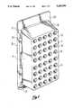
- FIG. 1is perspective view of a preferred embodiment of the apparatus invention illustrating including means for being removably secured to a wall or the like;
- FIG. 2is a side sectional view of the apparatus
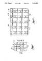
- FIG. 3is a plan view of the needle hub engaging and locking plate of the apparatus illustrating a portion thereof;
- FIG. 4is an enlarged view of a portion of the plate of FIG. 3 showing the features of the preferred hub engaging and locking components;
- FIG. 5is a bottom view and FIG. 6 is a side view both showing a needle hub engaged and locked in the plate.
- FIGS. 1 and 2show the container of a preferred embodiment of the apparatus of the invention.
- the container 10comprises a top 12 having an outer surface 11 on which are exposed a plurality of ports 14.
- the portsmay be arranged on the outer surface in any desired configuration, and that shown in which the ports are axially aligned in parallel rows may be preferred, but is not critical. However, it will be understood that a configuration which maximizes the number of the ports for a given container size, may be preferred. In addition, preferred configurations of the ports may also provide for ease of visually ascertaining which ports are unused and available for inserting a needle.
- the containerincludes a side 19, which entirely surrounds and defines a cavity in to which the needle cannulae safely extend.
- the sidemust provide a sufficient cavity depth between the top and bottom of the container to allow the capture of needle cannulae of the maximum length normally found or used in the institution in which the apparatus is used.
- the containeralso preferably includes a bottom wall which thus encloses the cavity in which the captured needle cannulae will project whereby the container may be readily handled by persons without danger of being injured by any contact with a needle cannula point.
- the containermay be molded to minimize the number of components. However, for assembly purposes, the top and/or bottom are molded as separate components so that the hub engaging plate component can be readily installed during assembly. Thereafter, any separate container components may be glued, fused, or otherwise secured together in final product assembly.
- the apparatusmay also include means for being removably secured on a wall bracket mounted on a wall, door, or similar surface for convenient accessibility.
- a wall plate 27for being attached to a wall, door, or the like, and having a bracket 26 extending along opposite sides or edges thereof may be conveniently used for removably securing container 10.
- Flanges 24 formed and extending from bottom plate 17, or other equivalent means for being inserted in the bracketsmay be used.
- the bracketsmay also include a stop member 13 projecting into the bottom of the track or groove between bracket 26 and wall plate surface 27 may be provided for preventing the container inserted in the brackets from gravitationally falling from the holder.
- Other suitable meansmay also be used for installing the container in a desirable and readily accessible location for use, and having means for being secured and conveniently removed for disposal.
- FIGS. 3 and 4illustrate the improved hub engaging, locking and capturing components of the apparatus of the invention.
- Plate 18preferably comprises a metal material such as steel, particularly stainless steel or spring steel, which is flexible, and at the same time is memory retaining i.e., spring-like and which tends to return toward its original position after bending, flexing, etc.
- Plate 18is provided with a plurality of needle hub engaging and locking components each consisting of a first member 20 having a hub engaging edge 26 and a second member 24 having a hub engaging edge 28.
- These first and second membersare formed as flexible leafs or fingers, each connected to the plate along one end, and which members are otherwise separated from the plate along both sides and along the hub engaging edges, opposite the plate connection ends, whereby the hub engaging ends are free to be moved.
- the hub engaging edges of the two membersare substantially coplanar and face one another prior to insertion of a needle hub therebetween.
- the hub engaging edges of the respective membersare separated by a space 30 having a maximum dimension that is less than the maximum cross-sectional dimension of the hub to be inserted and engaged by the edges.
- the plateis preferably made of a stainless steel plate having a substantially uniform thickness of between about 0.009 inch and about 0.011 inch thickness. It has been found that such a thickness lends itself well to meet the requirements of capturing a needle hub inserted between the members.
- Such metal plate thicknessprovides for members flexible enough to become spread apart by the needle hub inserted between the hub engaging edges, and yet which are not so flexible as to easily bend to allow the hub to be pulled back out when a hypodermic needle barrel is pulled away from an engaged hub. If the metal plate is thicker than about 0.011 inch, the members will be too stiff and not sufficiently flexible to readily spread the locking components apart by urging the needle hub therebetween. On the other hand, where the plate thickness is less than about 0.009 inch, the components are almost foil-like and are so flexible that they offer insufficient resistance to prevent an engaged needle hub from being pulled back out through the hub engaging edges.
- the apparatusis assembled and constructed so that opposite hub engaging edges of the first and second flexible members are centered relative to a port 14 in the top cover.
- the plate 18is also secured against the bottom surface 21 of the top cover 12. This may be provided by a number of means, for example, by screwing or bolting the plate to the under surface of the top cover, or by providing a series of small openings in the plate which are registered with nipples or guides extending downwardly from the bottom surface of the top cover having means for holding the plate against the surface.
- a preferred meansis illustrated in FIG.
- the container bottom 17includes a plurality of supports or ribs 32 which extend from the bottom plate 17 toward the top cover 12, and which ribs are of a length sufficient to hold the plate 18 against the bottom surface 2 of the top cover 12 when the container is assembled.
- ribs 32are preferably spaced and positioned to contact the plate between adjacent hub engaging and locking components whereby movement or flexibility of the hub engaging members to capture a needle hub is not affected. The ribs support the plate in the secured position against the top cover, without bending, forcing or springing the metal plate from its substantially planar condition.
- a plurality of bosses 41may be provided along the underside of top cover 12, to act as additional supports for plate 14 along the opposite side from ribs 32. Thus, the plate 14 is firmly secured between the bosses and ribs.
- the hub engaging edges of the first and second members 20 and 24, respectively,are each provided with an odd number of notches.
- Surface 28 of member 24has a single notch 25 substantially centered along edge 28, while edge 26 is provided with three notches, one notch 22 of which is centered along the edge.
- edge 26is provided with three notches, one notch 22 of which is centered along the edge.
- the two opposite and centered notches 22 and 25provide a centering aperture in space 30 so that when a needle hub is inserted into the space, it will be guided and become centered in its contact with each of the respective hub engaging surfaces.
- the two opposite hub engaging surfaceshave a different odd number of notches.
- edge 26is provided with three notches while edge 28 is provided with a single notch.
- notch hub engaging surfacea pair of teeth 29 and 31 as well as surface 28 are provided, one on each side of central notch 22. These teeth are important in engaging and capturing the softer needle hub, commonly made of plastic or aluminum, or other relatively soft material as compared to stainless steel.
- FIGS. 5 and 6illustrate the locking engagement and capture positions of the needle hub when it is secured between the members as described above. As shown, needle hub 40 is captured between flexible members 20 and 24, which have been bent in the direction in which the needle has been urged for its capture. A portion of needle cannula 42 is also shown.
- the ports 14 in top cover 12 into which the needle hubs are directed for being capturedcomprise a first orifice 15 and a second orifice 16
- First orifice 15has a diameter greater than the diameter of second orifice 16.
- the first port diameteris greater than the largest cross-sectional dimension of the needle hub locking tip of the barrel
- the second orificehas a diameter smaller than the largest cross-sectional dimension of the hub.
- Needle hubsalmost universally incorporate a flange 44 at the upper end of the needle hub opposite the cannula, which provides means for threadedly engaging or locking the hub in a hypodermic syringe incorporating locking threads in the locking tip of the barrel.
- the diameter of the flangenormally comprises the greatest cross-sectional dimension of the flange In a hypodermic syringe barrel tip incorporating a slip-type engagement with the needle hub, the locking flange of the hub is exposed on the exterior of the barrel.
- the hub having an exposed flangeWhen the hub having an exposed flange is inserted into the port, it may be urged therein until the flange is stopped from passing through the smaller orifice 16.
- hypodermic needle having a barrel provided with a threaded locking tip in which the needle hub flange is threadedly engagedbecause the diameter of such a locking tip is greater than the diameter of the smaller orifice, it will stop against the smaller orifice, to prevent further insertion of the hub.
- Another preferred and improved feature of the present inventionis in the position of plate 18 relative to the smaller orifice 16 as illustrated particularly in FIGS. 2 and 4. With plate 18 being urged to rest against the lower, interior surface 21 of top cover 12, the flexible members 20 and 24 rest against top cover interior surface 21 with the exception of the portion of the members exposed in orifice 16. Because the diameter of orifice 16, represented by the dash lines in FIG. 4, is not great relative to the surface area of either of the flexible members, the movement of the flexible members 20 and 24 from their original coplanar position toward or in the direction of orifice 16 is highly restricted. Preferably, the size of orifice 16 exposes less than 50% of a flexible member surface, and more preferably less than 33%. Such a feature provides a significant safety margin in further preventing retraction or recovery of the needle hub and needle cannula once they have been captured by having been inserted and engaged between the members.
- the userWhen using the apparatus of the invention, the user simply inserts a hypodermic needle, cannula point first, into one of the ports on the top cover. As the user continues to insert the hypodermic needle into the port, the hub will become engaged between the facing hub engaging surfaces. Urging of the hypodermic needle is continued until the locking flange of the hub contacts the small inner port orifice and can no longer be forced further into the port or until the enlarged locking tip of a threaded (Luer lock) type of barrel is stopped by the small orifice. At that time, the hub and needle cannula are fully engaged and captured, and the user then simply pulls the hypodermic needle syringe away from the hub. The apparatus may be used until all of the ports are filled, and thereafter discarded.
Landscapes
- Health & Medical Sciences (AREA)
- Engineering & Computer Science (AREA)
- Heart & Thoracic Surgery (AREA)
- Vascular Medicine (AREA)
- Anesthesiology (AREA)
- Biomedical Technology (AREA)
- Environmental & Geological Engineering (AREA)
- Hematology (AREA)
- Life Sciences & Earth Sciences (AREA)
- Animal Behavior & Ethology (AREA)
- General Health & Medical Sciences (AREA)
- Public Health (AREA)
- Veterinary Medicine (AREA)
- Infusion, Injection, And Reservoir Apparatuses (AREA)
Abstract
Description
Claims (15)
Priority Applications (1)
| Application Number | Priority Date | Filing Date | Title |
|---|---|---|---|
| US07/856,631US5285896A (en) | 1992-03-25 | 1992-03-25 | Apparatus for receiving and capturing a hypodermic needle hub and cannula |
Applications Claiming Priority (1)
| Application Number | Priority Date | Filing Date | Title |
|---|---|---|---|
| US07/856,631US5285896A (en) | 1992-03-25 | 1992-03-25 | Apparatus for receiving and capturing a hypodermic needle hub and cannula |
Publications (1)
| Publication Number | Publication Date |
|---|---|
| US5285896Atrue US5285896A (en) | 1994-02-15 |
Family
ID=25324126
Family Applications (1)
| Application Number | Title | Priority Date | Filing Date |
|---|---|---|---|
| US07/856,631Expired - LifetimeUS5285896A (en) | 1992-03-25 | 1992-03-25 | Apparatus for receiving and capturing a hypodermic needle hub and cannula |
Country Status (1)
| Country | Link |
|---|---|
| US (1) | US5285896A (en) |
Cited By (20)
| Publication number | Priority date | Publication date | Assignee | Title |
|---|---|---|---|---|
| US5564565A (en)* | 1994-09-14 | 1996-10-15 | Yamada; Todd H. | Disposable hypodermic needle receptacle |
| US5829589A (en)* | 1997-09-12 | 1998-11-03 | Becton Dickinson And Company | Pen needle magazine dispenser |
| US5850917A (en)* | 1996-12-23 | 1998-12-22 | Denton; George D. | Syringe dosage tracking device with cooling feature |
| US5913417A (en)* | 1995-06-05 | 1999-06-22 | Ovadia; Joseph | Jewelry pads having recesses, projections and/or plugs for holding jewelry items |
| US6098802A (en)* | 1998-12-17 | 2000-08-08 | Michael Hoffman | Deep well rack assembly for pipette tips and the like |
| US6123193A (en)* | 1999-10-07 | 2000-09-26 | Arrow International, Inc. | Sharps container |
| US6346094B2 (en)* | 1998-09-28 | 2002-02-12 | Becton, Dickinson And Company | Pen needle magazine |
| US6511461B2 (en)* | 1999-12-22 | 2003-01-28 | Gambro Lundia Ab | Needle holding device |
| US20040260270A1 (en)* | 2003-06-17 | 2004-12-23 | Nahum Cohen | Fluid transfer device having removable needle cartridge |
| AU2001273974B2 (en)* | 2000-04-27 | 2005-08-18 | Siemens Aktiengesellschaft | Sortation system diverter switch |
| EP1655048A1 (en)* | 2004-11-03 | 2006-05-10 | Biofluid Systems Société Anonyme | Multifunctional device for syringes and method of use of such a device |
| US20080221549A1 (en)* | 2007-03-06 | 2008-09-11 | Nahum Cohen | Rapid injection device |
| US20100152660A1 (en)* | 2007-05-30 | 2010-06-17 | Eli Lilly And Company | Cartridge with multiple injection needles for a medication injection device |
| US8057434B2 (en) | 2004-03-31 | 2011-11-15 | Eli Lilly And Company | Injection apparatus having a needle cassette for delivering a pharmaceutical liquid |
| US20120118777A1 (en)* | 2010-11-11 | 2012-05-17 | Arte Corporation | Packaging Plate, Syringe-Holding Container, and Method of Manufacturing Combined Container-Syringe |
| JP2013501554A (en)* | 2009-08-12 | 2013-01-17 | サノフィ−アベンティス・ドイチュラント・ゲゼルシャフト・ミット・ベシュレンクテル・ハフツング | Cap for portable drug delivery device and such drug delivery device |
| US9149578B2 (en) | 2010-11-19 | 2015-10-06 | Eli Lilly And Company | Needle cartridge for medication injection device |
| FR3039070A1 (en)* | 2015-07-22 | 2017-01-27 | Aurelien Rous | COLLECTOR FOR SYRINGES FOR SEPARATING THE NEEDLE FROM THE BODY OF THE SYRINGE |
| US10485625B1 (en)* | 2018-02-19 | 2019-11-26 | Gayle MISLE | Sterile stand for supporting surgical instruments |
| US20200237999A1 (en)* | 2019-01-28 | 2020-07-30 | Becton, Dickinson And Company | Needle Packaging |
Citations (14)
| Publication number | Priority date | Publication date | Assignee | Title |
|---|---|---|---|---|
| US3876067A (en)* | 1973-08-07 | 1975-04-08 | Helmut Schwarz | Collection box for syringe needles |
| US4351434A (en)* | 1979-01-31 | 1982-09-28 | Benjamin Elisha | Disposal of needles |
| US4488643A (en)* | 1983-10-28 | 1984-12-18 | Bemis Manufacturing Company | Syringe and needle disposal system |
| US4494652A (en)* | 1983-07-01 | 1985-01-22 | Winfield Industries | Container for sharps |
| US4520926A (en)* | 1984-02-27 | 1985-06-04 | Winfield Corp. | Container for sharps |
| US4883173A (en)* | 1989-06-01 | 1989-11-28 | Goldman Diana L | Hypodermic needle removal and disposal device |
| US4919264A (en)* | 1988-08-04 | 1990-04-24 | Shinall Kimberly A | Medical needle removing and disposing system |
| US4973315A (en)* | 1987-11-11 | 1990-11-27 | Ausmedics Pty Ltd. | Removal and safe disposal of sharps from medical tools |
| US4984686A (en)* | 1989-01-17 | 1991-01-15 | Med-Safe Systems, Inc. | Sharps container closure and needle extractor assembly |
| US5024327A (en)* | 1990-03-26 | 1991-06-18 | Med-Safe Systems, Inc. | Restricted access opening for disposable sharps containers |
| US5039004A (en)* | 1989-01-24 | 1991-08-13 | Hemox Corporation | Medical appliance disposal container |
| US5038929A (en)* | 1990-06-07 | 1991-08-13 | Susanne Kubofcik | Sharps disposal system |
| US5047019A (en)* | 1987-11-11 | 1991-09-10 | Ausmedics Pty. Ltd. | Device for the safe removal and disposal of sharps from medical tools |
| US5086922A (en)* | 1990-06-12 | 1992-02-11 | Medical Safety Products, Inc. | Disposal for needles and syringes |
- 1992
- 1992-03-25USUS07/856,631patent/US5285896A/ennot_activeExpired - Lifetime
Patent Citations (14)
| Publication number | Priority date | Publication date | Assignee | Title |
|---|---|---|---|---|
| US3876067A (en)* | 1973-08-07 | 1975-04-08 | Helmut Schwarz | Collection box for syringe needles |
| US4351434A (en)* | 1979-01-31 | 1982-09-28 | Benjamin Elisha | Disposal of needles |
| US4494652A (en)* | 1983-07-01 | 1985-01-22 | Winfield Industries | Container for sharps |
| US4488643A (en)* | 1983-10-28 | 1984-12-18 | Bemis Manufacturing Company | Syringe and needle disposal system |
| US4520926A (en)* | 1984-02-27 | 1985-06-04 | Winfield Corp. | Container for sharps |
| US4973315A (en)* | 1987-11-11 | 1990-11-27 | Ausmedics Pty Ltd. | Removal and safe disposal of sharps from medical tools |
| US5047019A (en)* | 1987-11-11 | 1991-09-10 | Ausmedics Pty. Ltd. | Device for the safe removal and disposal of sharps from medical tools |
| US4919264A (en)* | 1988-08-04 | 1990-04-24 | Shinall Kimberly A | Medical needle removing and disposing system |
| US4984686A (en)* | 1989-01-17 | 1991-01-15 | Med-Safe Systems, Inc. | Sharps container closure and needle extractor assembly |
| US5039004A (en)* | 1989-01-24 | 1991-08-13 | Hemox Corporation | Medical appliance disposal container |
| US4883173A (en)* | 1989-06-01 | 1989-11-28 | Goldman Diana L | Hypodermic needle removal and disposal device |
| US5024327A (en)* | 1990-03-26 | 1991-06-18 | Med-Safe Systems, Inc. | Restricted access opening for disposable sharps containers |
| US5038929A (en)* | 1990-06-07 | 1991-08-13 | Susanne Kubofcik | Sharps disposal system |
| US5086922A (en)* | 1990-06-12 | 1992-02-11 | Medical Safety Products, Inc. | Disposal for needles and syringes |
Cited By (28)
| Publication number | Priority date | Publication date | Assignee | Title |
|---|---|---|---|---|
| US5564565A (en)* | 1994-09-14 | 1996-10-15 | Yamada; Todd H. | Disposable hypodermic needle receptacle |
| US5913417A (en)* | 1995-06-05 | 1999-06-22 | Ovadia; Joseph | Jewelry pads having recesses, projections and/or plugs for holding jewelry items |
| US5850917A (en)* | 1996-12-23 | 1998-12-22 | Denton; George D. | Syringe dosage tracking device with cooling feature |
| US5829589A (en)* | 1997-09-12 | 1998-11-03 | Becton Dickinson And Company | Pen needle magazine dispenser |
| US6346094B2 (en)* | 1998-09-28 | 2002-02-12 | Becton, Dickinson And Company | Pen needle magazine |
| US6098802A (en)* | 1998-12-17 | 2000-08-08 | Michael Hoffman | Deep well rack assembly for pipette tips and the like |
| US6123193A (en)* | 1999-10-07 | 2000-09-26 | Arrow International, Inc. | Sharps container |
| WO2001026998A1 (en)* | 1999-10-07 | 2001-04-19 | Arrow International, Inc. | Sharps container |
| US6276527B1 (en)* | 1999-10-07 | 2001-08-21 | Arrow International, Inc. | Sharps container |
| US6511461B2 (en)* | 1999-12-22 | 2003-01-28 | Gambro Lundia Ab | Needle holding device |
| AU2001273974B2 (en)* | 2000-04-27 | 2005-08-18 | Siemens Aktiengesellschaft | Sortation system diverter switch |
| US7361163B2 (en)* | 2003-06-17 | 2008-04-22 | Adst Technologies. Ltd. | Fluid transfer device having removable needle cartridge |
| US20040260270A1 (en)* | 2003-06-17 | 2004-12-23 | Nahum Cohen | Fluid transfer device having removable needle cartridge |
| US20080154235A1 (en)* | 2003-06-17 | 2008-06-26 | Nahum Cohen | Fluid transfer device having removable needle cartridge |
| US8529522B2 (en)* | 2003-06-17 | 2013-09-10 | Adst Technologies Ltd. | Fluid transfer device having removable needle cartridge |
| US8057434B2 (en) | 2004-03-31 | 2011-11-15 | Eli Lilly And Company | Injection apparatus having a needle cassette for delivering a pharmaceutical liquid |
| EP1655048A1 (en)* | 2004-11-03 | 2006-05-10 | Biofluid Systems Société Anonyme | Multifunctional device for syringes and method of use of such a device |
| WO2006047898A1 (en)* | 2004-11-03 | 2006-05-11 | Biofluid Systems Sa | Multi-purpose device for syringes and use method thereof |
| US20080221549A1 (en)* | 2007-03-06 | 2008-09-11 | Nahum Cohen | Rapid injection device |
| US20100152660A1 (en)* | 2007-05-30 | 2010-06-17 | Eli Lilly And Company | Cartridge with multiple injection needles for a medication injection device |
| JP2013501554A (en)* | 2009-08-12 | 2013-01-17 | サノフィ−アベンティス・ドイチュラント・ゲゼルシャフト・ミット・ベシュレンクテル・ハフツング | Cap for portable drug delivery device and such drug delivery device |
| US20120118777A1 (en)* | 2010-11-11 | 2012-05-17 | Arte Corporation | Packaging Plate, Syringe-Holding Container, and Method of Manufacturing Combined Container-Syringe |
| US9149578B2 (en) | 2010-11-19 | 2015-10-06 | Eli Lilly And Company | Needle cartridge for medication injection device |
| FR3039070A1 (en)* | 2015-07-22 | 2017-01-27 | Aurelien Rous | COLLECTOR FOR SYRINGES FOR SEPARATING THE NEEDLE FROM THE BODY OF THE SYRINGE |
| US10485625B1 (en)* | 2018-02-19 | 2019-11-26 | Gayle MISLE | Sterile stand for supporting surgical instruments |
| US20200237999A1 (en)* | 2019-01-28 | 2020-07-30 | Becton, Dickinson And Company | Needle Packaging |
| US10864316B2 (en)* | 2019-01-28 | 2020-12-15 | Becton, Dickinson And Company | Needle packaging |
| US11376359B2 (en) | 2019-01-28 | 2022-07-05 | Becton, Dickinson And Company | Needle packaging |
Similar Documents
| Publication | Publication Date | Title |
|---|---|---|
| US5285896A (en) | Apparatus for receiving and capturing a hypodermic needle hub and cannula | |
| US10052438B2 (en) | Tamper evident needle guard for syringes | |
| US8226617B2 (en) | Safety shield apparatus and mounting structure for use with medical needle devices | |
| US5046612A (en) | Safety apparatus for extracting hypodermic needles from the respective syringe | |
| US5259840A (en) | Locking syringe | |
| JP4173631B2 (en) | Disposable self-shielding unit dose syringe guard | |
| US5584816A (en) | Hardpack shield for a pivoting needle guard | |
| JP3946324B2 (en) | Medical infusion device having a lockable safety shield | |
| US5683368A (en) | Controlled motion lock for safety catheter | |
| US6991618B2 (en) | Single use syringe and plunger rod locking device therefor | |
| EP0832660A2 (en) | Shielded needle assembly | |
| US4875265A (en) | Injection needle-detaching device | |
| US5230428A (en) | Apparatus for the disposal of contaminated needles | |
| NZ223656A (en) | Catheter placement device: includes needle guard | |
| US5472433A (en) | Disposable safety guard for syringe needles and the like | |
| US5334173A (en) | Stabilizing foot means for cap of needle assembly and method thereof | |
| AU3783385A (en) | Improved syringe needle sheath and shield | |
| EP0304619A2 (en) | Injection needle-detaching device and container having said device | |
| WO1994010915A1 (en) | A medical tool organizing device | |
| EP0425448B1 (en) | Safety cap for a medical needle after use | |
| US5368580A (en) | Disposable safety guard for syringe needles and the like | |
| US6306118B1 (en) | Needle holder assembly | |
| US6485459B1 (en) | Retractable non-reusable needle | |
| US20240016519A1 (en) | Apparatus and method for removing intra-osseous device | |
| EP1262207A1 (en) | Needle protection holder |
Legal Events
| Date | Code | Title | Description |
|---|---|---|---|
| AS | Assignment | Owner name:TIMELY MEDICAL INNOVATIONS, LTD. A CA CORPORATI Free format text:ASSIGNMENT OF ASSIGNORS INTEREST.;ASSIGNORS:SALATKA, ROBERT G.;BUCK, WILLIAM B.;MITCHELL, JAMES H.;AND OTHERS;REEL/FRAME:006068/0884;SIGNING DATES FROM 19920318 TO 19920324 | |
| STCF | Information on status: patent grant | Free format text:PATENTED CASE | |
| FPAY | Fee payment | Year of fee payment:4 | |
| FPAY | Fee payment | Year of fee payment:8 | |
| FPAY | Fee payment | Year of fee payment:12 | |
| AS | Assignment | Owner name:FOURTH THIRD, LLC, NEW YORK Free format text:ASSIGNMENT OF ASSIGNORS INTEREST;ASSIGNOR:TIMELY MEDICAL INNOVATIONS, LLC;REEL/FRAME:018679/0321 Effective date:20061226 | |
| AS | Assignment | Owner name:TIMELY MEDICAL INNOVATIONS, LLC, CALIFORNIA Free format text:ASSIGNMENT OF ASSIGNORS INTEREST;ASSIGNOR:TIMELY MEDICAL INNOVATIONS, LTD;REEL/FRAME:020206/0097 Effective date:20061010 | |
| AS | Assignment | Owner name:TIMELY MEDICAL INNOVATIONS, LLC,CALIFORNIA Free format text:RELEASE BY SECURED PARTY;ASSIGNOR:FOURTH THIRD, LLC;REEL/FRAME:024390/0154 Effective date:20100514 Owner name:MADISON CAPITAL FUNDING LLC, AS AGENT,ILLINOIS Free format text:SECURITY AGREEMENT;ASSIGNOR:TIDI PRODUCTS, LLC;REEL/FRAME:024390/0274 Effective date:20100514 Owner name:MADISON CAPITAL FUNDING LLC, AS AGENT, ILLINOIS Free format text:SECURITY AGREEMENT;ASSIGNOR:TIDI PRODUCTS, LLC;REEL/FRAME:024390/0274 Effective date:20100514 | |
| AS | Assignment | Owner name:TIDI PRODUCTS, LLC,WISCONSIN Free format text:ASSIGNMENT OF ASSIGNORS INTEREST;ASSIGNOR:TIMELY MEDICAL INNOVATIONS, LLC;REEL/FRAME:024402/0208 Effective date:20100514 Owner name:TIDI PRODUCTS, LLC, WISCONSIN Free format text:ASSIGNMENT OF ASSIGNORS INTEREST;ASSIGNOR:TIMELY MEDICAL INNOVATIONS, LLC;REEL/FRAME:024402/0208 Effective date:20100514 | |
| AS | Assignment | Owner name:MADISON CAPITAL FUNDING LLC, AS AGENT, ILLINOIS Free format text:SECURITY AGREEMENT;ASSIGNOR:TIDI PRODUCTS, LLC;REEL/FRAME:028583/0269 Effective date:20120717 Owner name:TIDI PRODUCTS, LLC, WISCONSIN Free format text:RELEASE BY SECURED PARTY;ASSIGNOR:MADISON CAPITAL FUNDING LLC, AS AGENT;REEL/FRAME:028572/0740 Effective date:20120717 | |
| AS | Assignment | Owner name:TIDI PRODUCTS, LLC, WISCONSIN Free format text:RELEASE BY SECURED PARTY;ASSIGNOR:MADISON CAPITAL FUNDING LLC, AS AGENT;REEL/FRAME:036010/0973 Effective date:20150701 |