US5285236A - Large-area, high-throughput, high-resolution projection imaging system - Google Patents
Large-area, high-throughput, high-resolution projection imaging systemDownload PDFInfo
- Publication number
- US5285236A US5285236AUS07/954,662US95466292AUS5285236AUS 5285236 AUS5285236 AUS 5285236AUS 95466292 AUS95466292 AUS 95466292AUS 5285236 AUS5285236 AUS 5285236A
- Authority
- US
- United States
- Prior art keywords
- substrate
- mask
- subsystem
- stage
- illumination
- Prior art date
- Legal status (The legal status is an assumption and is not a legal conclusion. Google has not performed a legal analysis and makes no representation as to the accuracy of the status listed.)
- Expired - Lifetime
Links
- 238000003384imaging methodMethods0.000titleclaimsabstractdescription59
- 239000000758substrateSubstances0.000claimsabstractdescription116
- 238000005286illuminationMethods0.000claimsabstractdescription60
- 230000000694effectsEffects0.000claimsabstract10
- 239000000654additiveSubstances0.000claimsabstract5
- 230000000996additive effectEffects0.000claimsabstract5
- 230000003287optical effectEffects0.000claimsdescription18
- 230000005855radiationEffects0.000claimsdescription11
- 238000000034methodMethods0.000claimsdescription10
- CURLTUGMZLYLDI-UHFFFAOYSA-NCarbon dioxideChemical compoundO=C=OCURLTUGMZLYLDI-UHFFFAOYSA-N0.000claimsdescription4
- QSHDDOUJBYECFT-UHFFFAOYSA-NmercuryChemical compound[Hg]QSHDDOUJBYECFT-UHFFFAOYSA-N0.000claimsdescription3
- 229910052753mercuryInorganic materials0.000claimsdescription3
- 229910052779NeodymiumInorganic materials0.000claimsdescription2
- 229910002092carbon dioxideInorganic materials0.000claimsdescription2
- 239000001569carbon dioxideSubstances0.000claimsdescription2
- 238000010894electron beam technologyMethods0.000claimsdescription2
- QEFYFXOXNSNQGX-UHFFFAOYSA-Nneodymium atomChemical compound[Nd]QEFYFXOXNSNQGX-UHFFFAOYSA-N0.000claimsdescription2
- 230000003362replicative effectEffects0.000claims2
- 238000000926separation methodMethods0.000claims2
- 238000012544monitoring processMethods0.000claims1
- 238000000059patterningMethods0.000description26
- 238000004519manufacturing processMethods0.000description14
- 208000032005Spinocerebellar ataxia with axonal neuropathy type 2Diseases0.000description7
- 208000033361autosomal recessive with axonal neuropathy 2 spinocerebellar ataxiaDiseases0.000description7
- 230000008901benefitEffects0.000description7
- 238000005516engineering processMethods0.000description7
- 230000007246mechanismEffects0.000description7
- 239000004065semiconductorSubstances0.000description4
- 230000000295complement effectEffects0.000description3
- 238000002508contact lithographyMethods0.000description3
- 230000007547defectEffects0.000description3
- 239000000463materialSubstances0.000description3
- 239000002131composite materialSubstances0.000description2
- VSQYNPJPULBZKU-UHFFFAOYSA-Nmercury xenonChemical compound[Xe].[Hg]VSQYNPJPULBZKU-UHFFFAOYSA-N0.000description2
- 238000004377microelectronicMethods0.000description2
- 229920002120photoresistant polymerPolymers0.000description2
- 150000003071polychlorinated biphenylsChemical class0.000description2
- 229920000642polymerPolymers0.000description2
- 230000009467reductionEffects0.000description2
- 230000007704transitionEffects0.000description2
- 235000012431wafersNutrition0.000description2
- 206010034972Photosensitivity reactionDiseases0.000description1
- XUIMIQQOPSSXEZ-UHFFFAOYSA-NSiliconChemical compound[Si]XUIMIQQOPSSXEZ-UHFFFAOYSA-N0.000description1
- 230000000712assemblyEffects0.000description1
- 238000000429assemblyMethods0.000description1
- 230000015556catabolic processEffects0.000description1
- 230000002301combined effectEffects0.000description1
- 239000004020conductorSubstances0.000description1
- 230000001186cumulative effectEffects0.000description1
- 230000007423decreaseEffects0.000description1
- 238000006731degradation reactionMethods0.000description1
- 230000008030eliminationEffects0.000description1
- 238000003379elimination reactionMethods0.000description1
- 238000001914filtrationMethods0.000description1
- 238000010304firingMethods0.000description1
- 238000001459lithographyMethods0.000description1
- 229910001507metal halideInorganic materials0.000description1
- 150000005309metal halidesChemical class0.000description1
- 238000012986modificationMethods0.000description1
- 230000004048modificationEffects0.000description1
- 230000005693optoelectronicsEffects0.000description1
- 230000036211photosensitivityEffects0.000description1
- 238000007639printingMethods0.000description1
- 230000008569processEffects0.000description1
- 229910052710siliconInorganic materials0.000description1
- 239000010703siliconSubstances0.000description1
- 238000000638solvent extractionMethods0.000description1
- 230000003595spectral effectEffects0.000description1
- 230000001360synchronised effectEffects0.000description1
Images


Classifications
- G—PHYSICS
- G03—PHOTOGRAPHY; CINEMATOGRAPHY; ANALOGOUS TECHNIQUES USING WAVES OTHER THAN OPTICAL WAVES; ELECTROGRAPHY; HOLOGRAPHY
- G03F—PHOTOMECHANICAL PRODUCTION OF TEXTURED OR PATTERNED SURFACES, e.g. FOR PRINTING, FOR PROCESSING OF SEMICONDUCTOR DEVICES; MATERIALS THEREFOR; ORIGINALS THEREFOR; APPARATUS SPECIALLY ADAPTED THEREFOR
- G03F7/00—Photomechanical, e.g. photolithographic, production of textured or patterned surfaces, e.g. printing surfaces; Materials therefor, e.g. comprising photoresists; Apparatus specially adapted therefor
- G03F7/70—Microphotolithographic exposure; Apparatus therefor
- G03F7/70216—Mask projection systems
- G03F7/70358—Scanning exposure, i.e. relative movement of patterned beam and workpiece during imaging
Definitions
- This inventionrelates to an optical projection imaging system, and more particularly to a system for very high-speed imaging of high-resolution patterns for the production of high-performance electronic products with large areas, such as printed circuit boards, multichip modules, displays and semiconductor integrated circuits.
- the structurescan be active devices, such as transistors in a flat-panel display (FPD) of a semiconductor integrated circuit (IC), or passive patterns such as interconnecting conductors in a printed circuit board (PCB) or a multichip module (MCM).
- the large substratecan be a board, a display panel or a silicon wafer.
- the pattern sizes in these diverse productsrange from sub-micron for semiconductor ICs to multi-microns for displays, MCMs and PCBs.
- the substrate size requirementsvary from a few square inches for small modules to a few square feet for large PCBs and displays.
- a critical and common factor in the above applicationsis that they all require a large-area patterning system that can provide the required resolution over the entire substrate. Cost-effective production requirements also prefer systems with high processing throughputs.
- the patterning technology selecteddetermines not only the ultimate performance of the product, but also the economics of the entire manufacturing process through such key factors as throughput and yield. No patterning system currently exists that meets these criteria satisfactorily.
- the disclosed inventiondescribes a system technology that delivers all of the desired performance and cost features in a patterning system, namely, large-area capability, high resolution, high throughput, and high yield.
- a representative contact printer for volume manufacturingconsists of a fixture to align and hold the substrate in contact with the mask, and a collimated high-intensity light source to flash expose the mask pattern onto the substrate.
- Such systemssometimes feature a two-drawer substrate handling facility, allowing the user to load a second substrate while a first is being exposed; double-sided drawers may allow exposure of opposite substrate sides simultaneously or sequentially.
- Most contact printersuse mercury-xenon or metal-halide lamps, with powers ranging from 2 to 8 kW.
- a representative single-field projection systemuses a 1:1 magnification lens for imaging the mask pattern onto the substrate, a 1-2 kW mercury-xenon arc lamp, a heat-filtering mirror, and a condenser to direct the radiation to the mask. For different resolution requirements, the maximum image field of the projection lens is different.
- Step-and-repeat systemsuse reduction imaging, typically in the range 2:1-10:1. Generally, systems with larger reduction ratios provide higher resolution, but also lower throughput.
- Laser direct writing systemswhich write the pattern on the substrate with a focused scanning beam, suffer from an inherently slow speed due to their bit-by-bit, serial mode of addressing.
- a representative direct writing systemuses a focused blue or ultraviolet laser beam in a raster scanning fashion to expose each pixel on the substrate. The focused spot is moved across the substrate in one dimension, while the stage holding the substrate is translated in the orthogonal dimension. Due to serial addressing, the processing times for direct-write systems are long, ranging from a few minutes to a few hours per substrate, depending upon the resolution and complexity of the pattern data.
- This inventionprovides a projection imaging system which can pattern very large microelectronic boards, display panels or semiconductor wafers (for ease of discussion the term ⁇ substrate ⁇ will be used) at high production speeds and with high resolution.
- Light from a lamp or laser sourceis modified to provide an equal-intensity, regular-hexagon-shaped illumination beam across which the substrate is moved in a scan-and-repeat fashion to achieve uniform, seamless exposure over the entire substrate surface.
- the hexagonal illumination beameffectively scans the length of the substrate; the width of the substrate is covered by repeating many such scans. Adjacent scans are made to partially overlap--in such a way that in the overlap region the exposures from the two scans are complementary whose sum equals the exposure in the non-overlapping regions, leading to a uniform, seamless exposure of the whole substrate.
- the scan-and-repeat seamless exposure mechanismrequires that the mask be moved in synchronism with the substrate. Since most projection lenses cause image reversal, the direction of mask movement must be opposite that of the substrate. For high-throughput, cost-effective production it is desireable that the mask and substrate stages move in the same direction, and preferably as a single unit.
- the mask and the substrateare held on a single stage, making it possible to feed substrates automatically at a high rate. Image reversal by the projection lens is avoided by re-reversing the image using additional optical means.
- a feature of the inventionis a scan-and-repeat exposure mechanism which produces uniform, seamless exposure of the whole substrate surface by multiple scans which so overlap that exposures from adjacent scans in overlapping regions are complementary.
- Another feature of the inventionis the provision of a uniform hexagonal illumination beam.
- Another feature of the inventionis the provision of a single stage assembly for holding both the mask and the substrate in mutually locked positions.
- Another feature of the inventionis the provision of an integrated, automated substrate feed mechanism.
- Still another feature of the inventionis the provision of a projection system that includes optical means to produce non-reversing images.
- An advantage of the inventionis the elegant simplicity of its mechanical and optical systems, resulting in a highly efficient, versatile, and economical patterning system.
- Another advantage of the inventionis the elimination of the trade-off between high resolution and large field size, which thereby delivers both of these performance features without limitations.
- Another advantage of the inventionis its high processing throughput.
- Another advantage of the inventionis its provision for locked mask and substrate movement, enabling high-precision patterning.
- Still another advantage of the inventionis its provision for easy and fast substrate loading.
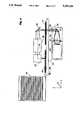
- FIG. 1is a composite illustration of the preferred embodiment of a large-area, high-throughput, high-resolution scan-and-repeat patterning system, showing an illumination system, a stage holding a mask and a substrate, a projection lens assembly, and optical image reversing means.
- the stagescans longitudinally in the x-direction and moves laterally along y between scans.
- FIG. 2shows the circular, square and rectangular image fields of the projection lens, the hexagonal cross section of the illumination beam, and the effective scan width w.
- FIG. 3illustrates the scan-and-repeat mechanism, showing three adjacent scans generated by overlapping hexagonal illumination beams and the complementary exposure in the overlap regions which generate the seamless transitions between adjacent scans.
- the figurealso shows the scan direction alternating between +x and -x, and the lateral movements by w between scans.
- FIG. 4shows the addition of an automatic substrate feeder to the embodiment of FIG. 1 to facilitate high-throughput production.
- FIG. 5illustrates a variation of the embodiment of FIG. 4, showing the mask and the substrate mounted vertically on a vertical stage which scans in a horizontal direction.
- FIG. 6is a composite illustration of an alternate embodiment of the invention, showing an illumination system, a dual-platform stage, and a projection assembly which comprises a concave mirror as the main imaging element and prisms for folding and image reversal.
- the patterning of the substratetakes place by scanning either the stage or the projection assembly.
- FIG. 7shows optical means for use in the embodiment of FIG. 6 to move the illumination beam in synchronism with the projection assembly.
- FIG. 8illustrates the principle of simultaneous two-dimensional scan-and-repeat seamless imaging for large-area patterning.
- FIG. 1illustrates the preferred embodiment of the new projection imaging system.
- the substrate 10 and mask 14are held rigidly on a stage 12.
- the stage 12is capable of scanning longitudinally in the x-direction (left-right) and moving laterally in the y-direction (perpendicular to the plane of the paper).
- the illumination system 18consists of a source system 20, a relay lens 22, and beam steering optics 24.
- the source system 20is such that its effective emission plane 21 is in the shape of a regular hexagon.
- the relay lens 22collects radiation from the effective emission plane 21 and directs it on the mask 14.
- a 1:1 projection lens assembly 26, consisting of several individual lens elements,forms a precise image of the pattern contained within the illuminated hexagonal region on the mask 14 onto the substrate 10.
- the optical pathalso includes a folding mirror 25 and optical reversing means 27 consisting of mirrors or prisms.
- the function of the reversing unitis to undo the image reversal caused by the lens 26.
- the combined effect of lens 26 and reverser 27is to image the illuminated mask pattern, without changing its orientation, onto the substrate.
- the projection lens assembly 26has a numerical aperture determined by the resolution requirements of the patterning system and is designed for as large a circular image field as possible (shown by 31 in FIG. 2).
- the illumination region on the mask(and therefore also the exposure region on the substrate) is then defined as the largest regular hexagon (shown by 32 in FIG. 2) that can be inscribed within the above circular field.
- the stageis scanned in the x-direction so that the length of the mask traverses across its hexagonal illumination region. This results in the substrate being simultaneously scanned across its hexagonal exposure region.
- the illumination beam 23is stationary, as are the projection lens assembly 26 and the reversing optical means 27.
- FIG. 3illustrates the details of the mechanism of seamless overlapping hexagon scanning.
- the regular hexagon 36also shown as a-b-g-j-h-c, represents the illuminated region on the mask at any time.
- the first x-scan of the substrate across its hexagonal exposure regionis depicted as scan 1, or 50.
- the orientation of the hexagon 36is such that one of its sides, for example b-g, is orthogonal to the scan direction.
- the stageis moved along y by the effective scan width w (52), defined as
- the transition from scan 1 to scan 2(and therefore the entire substrate) is seamless in exposure dose uniformity because (a) the doses provided by hexagons 36 and 38 taper in opposite directions in the overlapping region, and (b) they taper to zero at apex a and apex d, respectively.
- the hexagonal illuminationalso makes the most efficient utilization of the light source output and the projection lens aperture.
- the illumination areas with a hexagonal beam, a square beam, and a rectangular beam (of aspect ratio 2:1)will be, respectively,
- a hexagonal beamis 30% more efficient than a square beam and 62.5% more efficient than a rectangular beam of 2:1 aspect ratio.
- FIG. 4presents an embodiment illustrating the addition of an automatic substrate feeder 29 to the configuration of FIG. 1.
- the projection lens assembly 26is preferably an all-refractive system, typically consisting of 4-10 lens elements which are anti-reflection coated for the wavelength(s) of operation.
- mirror imaging systems, or combination refractive-reflective projection assembliesmay be considered.
- the reversing unit 27 in FIGS. 1 and 4is preferably an all-mirror assembly.
- the unit 27may consist of one or more prisms or a combination of prisms and mirrors.
- the stage 12 in FIGS. 1 and 4is preferably horizontal, as are the mask 14 and the substrate 10, and all their movements.
- the optical axis 19 of the projection lens assembly 26is also horizontal.
- the stage 12 with the mask 14 and the substrate 10 mounted on itcan be vertical.
- the longitudinal scan of the stagewill still be in a horizontal direction, but its lateral movements between two scans will be in a vertical direction.
- the optical axis 19 of the projection lens assembly 26will remain horizontal.
- FIG. 6Another embodiment of the invention is illustrated in FIG. 6.
- the projection system, shown as 30,uses a concave mirror 31 as its primary imaging element and two prisms (32, 33) for beam folding.
- the illumination system 18is as before in the embodiments of FIGS. 1, 4 and 5.
- the prism 32is a conventional right-angle prism, whereas the prism 33 has additional facets cut in it to produce reflections that re-reverse the image produced by the mirror 31, thereby preventing reversal of the final image produced by the total projection system 30.
- the projection assembly 30, the illumination system 18 and the illumination beam 23are held stationary, whereas the stage 11 is scanned along x and also stepped along y after each scan.
- the scanning movement of the stage (11/12) along the x-axiscan be effected by a stepping motor such that the total distance scanned is a multiple of a certain quantity d s , where d s is the minimum distance steppable by the scanning motor.
- the quantity d sis thus the scanning resolution of the stage.
- the scanning of the stagecan be electronically linked to the firing of the illumination source pulses. In such a configuration, with each pulse fired by the source, the stage travels one or more units of the distance d s , so that if v x is the effective stage scanning speed and f the source pulse repetition rate, then d s is related to v x /f by an integral ratio.
- the stage 11may be held stationary, whereas the projection assembly 30, comprising the mirror (31) and the prisms (32, 33), may be scanned between the mask 14 and the substrate 10 and also stepped after each scan.
- the illumination beam 23 incident on the maskis moved in synchronism with the projection system 30. This can be done by translating the mirror 24 along the x-axis (or rocking it around the y-axis) to move the beam 23 longitudinally along the scan direction, and rocking the mirror around the x-axis to move the beam laterally (in the y-z plane).
- the beam steering optics 24may consist of two mirrors 34 and 35, in which case translating the two mirrors as a unit in the x-direction moves the beam 23 in the scan direction, and translating the mirror 35 alone in the y-direction moves the beam laterally.
- scanning of the unitary stageis carried out simultaneously both in the x- and y-dimensions.
- scanning in the x-dimensionbegins with scan 1 (80) from left to right, its direction reverses at the end of scan 1, scan 2 (82) is then carried out right to left, scan 3 (84) again left to right, scan 4 (86) right to laft, and so on.
- the illuminated region on the maskis hexagonal, the effective width of each x-scan is w, and the overlap between scans 1 and 3 (and between 2 and 4) is seamless.
- the stageis scanned continuously in the y-direction.
- the y-scan rateis such that during the time the stage takes to complete one round-trip x-scan, it moves in the y-direction by w.
- the source 20 in the illumination system 18is selected to optimally match the exposure requirements of the radiation-sensitive material applied on the substrate 10.
- a mercury lampis desirable as the illumination source.
- the radiation sourcemay be a continuous-wave source; in others, it may be pulsed at a certain repetition frequency.
- laser sourcesare desirable.
- a particular class of laser sources useful in imagingis excimer lasers, which are attractive for both wet and dry patterning of resists and polymers.
- Other laser sources, desirable in applications such as markinginclude carbon-dioxide and neodymium lasers. It is also possible to use sources other than those in the ultraviolet, visible and infrared optical spectral regions.
- an X-ray illumination sourcemay be desirable.
- the imaging assembly (26,27)will be an X-ray projection system consisting of suitable X-ray optics; alternatively, the imaging may take the form of shadow printing, in which case a proximity configuration may be used without a projection assembly.
- the imaging assembly(26,27) will be an X-ray projection system consisting of suitable X-ray optics; alternatively, the imaging may take the form of shadow printing, in which case a proximity configuration may be used without a projection assembly.
- an electron-beam sourcein proximity configuration in a scan-and-repeat seamless patterning system according to this invention.
- the inventiondescribes a method of providing a large-area, high-throughput, high-resolution scan-and-repeat patterning system using the following steps:
- the method of operationmay further include the step of periodically realigning the mask and substrate with respect to each other during the steps 5-7 above.
- the exposure throughputdefined as the area A exposed per unit time
- the scan-and-repeat patterning system described in this inventionis capable of producing very high throughputs as well as delivering very high resolution over very large areas.
- the patterning system described in this inventionalso requires significantly lower source power than prior-art contact and projection printers.
Landscapes
- Physics & Mathematics (AREA)
- General Physics & Mathematics (AREA)
- Exposure Of Semiconductors, Excluding Electron Or Ion Beam Exposure (AREA)
- Exposure And Positioning Against Photoresist Photosensitive Materials (AREA)
Abstract
Description
1. Field of the Invention
This invention relates to an optical projection imaging system, and more particularly to a system for very high-speed imaging of high-resolution patterns for the production of high-performance electronic products with large areas, such as printed circuit boards, multichip modules, displays and semiconductor integrated circuits.
2. Description of Related Art
Economical manufacturing of many electronic and opto-electronic products requires fabrication of millions of microscopic structures on a single large substrate. The structures can be active devices, such as transistors in a flat-panel display (FPD) of a semiconductor integrated circuit (IC), or passive patterns such as interconnecting conductors in a printed circuit board (PCB) or a multichip module (MCM). The large substrate can be a board, a display panel or a silicon wafer. The pattern sizes in these diverse products range from sub-micron for semiconductor ICs to multi-microns for displays, MCMs and PCBs. The substrate size requirements vary from a few square inches for small modules to a few square feet for large PCBs and displays.
A critical and common factor in the above applications is that they all require a large-area patterning system that can provide the required resolution over the entire substrate. Cost-effective production requirements also prefer systems with high processing throughputs. The patterning technology selected determines not only the ultimate performance of the product, but also the economics of the entire manufacturing process through such key factors as throughput and yield. No patterning system currently exists that meets these criteria satisfactorily. The disclosed invention describes a system technology that delivers all of the desired performance and cost features in a patterning system, namely, large-area capability, high resolution, high throughput, and high yield.
There are three primary types of patterning systems currently in wide use:
contact printing systems,
projection imaging systems, and
focused-beam laser direct writing systems.
Contact printing suffers from two inherent disadvantages: generation of defects during patterning, and mask life degradation. A representative contact printer for volume manufacturing consists of a fixture to align and hold the substrate in contact with the mask, and a collimated high-intensity light source to flash expose the mask pattern onto the substrate. Such systems sometimes feature a two-drawer substrate handling facility, allowing the user to load a second substrate while a first is being exposed; double-sided drawers may allow exposure of opposite substrate sides simultaneously or sequentially. Most contact printers use mercury-xenon or metal-halide lamps, with powers ranging from 2 to 8 kW.
Conventional single-field projection imaging systems eliminate the disadvantages of contact printing resulting from defects and wear, but are limited in the largest substrate size they can expose due to their small image field. Step-and-repeat projection systems overcome this constraint by partitioning the substrate into several segments; however, this decreases throughput and creates the difficult requirement of precisely stitching the segments together. A representative single-field projection system uses a 1:1 magnification lens for imaging the mask pattern onto the substrate, a 1-2 kW mercury-xenon arc lamp, a heat-filtering mirror, and a condenser to direct the radiation to the mask. For different resolution requirements, the maximum image field of the projection lens is different. For example, whereas a 1-mil resolution can be obtained over a 4-inch square field, a 1-micron resolution must be limited to a field diameter of 2-3 cm. Step-and-repeat systems use reduction imaging, typically in the range 2:1-10:1. Generally, systems with larger reduction ratios provide higher resolution, but also lower throughput.
Laser direct writing systems, which write the pattern on the substrate with a focused scanning beam, suffer from an inherently slow speed due to their bit-by-bit, serial mode of addressing. A representative direct writing system uses a focused blue or ultraviolet laser beam in a raster scanning fashion to expose each pixel on the substrate. The focused spot is moved across the substrate in one dimension, while the stage holding the substrate is translated in the orthogonal dimension. Due to serial addressing, the processing times for direct-write systems are long, ranging from a few minutes to a few hours per substrate, depending upon the resolution and complexity of the pattern data.
Thus, existing technologies for microelectronic patterning suffer from major shortcomings, including defect generation on substrate, mask wear, limitation of resolution or field size, and low throughput. Ideally, one desires the throughput of contact printers as well as the high resolution available from projection imaging and direct writing, without any of the disadvantages of the three technologies. There is thus a great need for developing a patterning system for fabrication of electronic products which combines three major performance attributes: high resolution, high processing throughput, and ability to handle large substrate sizes.
An imaging technology which achieves the above objectives has been described by this inventor in his U.S. Pat. No. 4,924,257, Scan and Repeat High Resolution Lithography System, issued May 8, 1990 (application Ser. No. 253,717, filed Oct. 5, 1988). The referenced patent discloses a patterning technology that uses synchronized mask and substrate stages which are moved in such a way that a large number of small image fields are joined together `seamlessly` without any nonuniformly exposed overlaps or unexposed gaps. This invention discloses a projection imaging system in which the objective of seamless exposure for large-area, high-resolution, high-throughput patterning is achieved using a single, integrated stage assembly for both mask and substrate.
This invention provides a projection imaging system which can pattern very large microelectronic boards, display panels or semiconductor wafers (for ease of discussion the term `substrate` will be used) at high production speeds and with high resolution. Light from a lamp or laser source is modified to provide an equal-intensity, regular-hexagon-shaped illumination beam across which the substrate is moved in a scan-and-repeat fashion to achieve uniform, seamless exposure over the entire substrate surface. The hexagonal illumination beam effectively scans the length of the substrate; the width of the substrate is covered by repeating many such scans. Adjacent scans are made to partially overlap--in such a way that in the overlap region the exposures from the two scans are complementary whose sum equals the exposure in the non-overlapping regions, leading to a uniform, seamless exposure of the whole substrate.
The scan-and-repeat seamless exposure mechanism requires that the mask be moved in synchronism with the substrate. Since most projection lenses cause image reversal, the direction of mask movement must be opposite that of the substrate. For high-throughput, cost-effective production it is desireable that the mask and substrate stages move in the same direction, and preferably as a single unit. In the scan-and-repeat projection imaging system described in this invention, the mask and the substrate are held on a single stage, making it possible to feed substrates automatically at a high rate. Image reversal by the projection lens is avoided by re-reversing the image using additional optical means.
It is the object of the invention to provide a projection imaging system which is capable of exposing large substrates uniformly, with high resolution, and with high processing rates.
It is another object of the invention to provide a projection imaging system which is production oriented and in which substrates can be fed automatically.
A feature of the invention is a scan-and-repeat exposure mechanism which produces uniform, seamless exposure of the whole substrate surface by multiple scans which so overlap that exposures from adjacent scans in overlapping regions are complementary.
Another feature of the invention is the provision of a uniform hexagonal illumination beam.
Another feature of the invention is the provision of a single stage assembly for holding both the mask and the substrate in mutually locked positions.
Another feature of the invention is the provision of an integrated, automated substrate feed mechanism.
Still another feature of the invention is the provision of a projection system that includes optical means to produce non-reversing images.
An advantage of the invention is the elegant simplicity of its mechanical and optical systems, resulting in a highly efficient, versatile, and economical patterning system.
Another advantage of the invention is the elimination of the trade-off between high resolution and large field size, which thereby delivers both of these performance features without limitations.
Another advantage of the invention is its high processing throughput.
Another advantage of the invention is its provision for locked mask and substrate movement, enabling high-precision patterning.
Still another advantage of the invention is its provision for easy and fast substrate loading.
Other objects, features and advantages of the invention will be apparent from the following specification and from the annexed drawings and claims.
FIG. 1 is a composite illustration of the preferred embodiment of a large-area, high-throughput, high-resolution scan-and-repeat patterning system, showing an illumination system, a stage holding a mask and a substrate, a projection lens assembly, and optical image reversing means. The stage scans longitudinally in the x-direction and moves laterally along y between scans.
FIG. 2 shows the circular, square and rectangular image fields of the projection lens, the hexagonal cross section of the illumination beam, and the effective scan width w.
FIG. 3 illustrates the scan-and-repeat mechanism, showing three adjacent scans generated by overlapping hexagonal illumination beams and the complementary exposure in the overlap regions which generate the seamless transitions between adjacent scans. The figure also shows the scan direction alternating between +x and -x, and the lateral movements by w between scans.
FIG. 4 shows the addition of an automatic substrate feeder to the embodiment of FIG. 1 to facilitate high-throughput production.
FIG. 5 illustrates a variation of the embodiment of FIG. 4, showing the mask and the substrate mounted vertically on a vertical stage which scans in a horizontal direction.
FIG. 6 is a composite illustration of an alternate embodiment of the invention, showing an illumination system, a dual-platform stage, and a projection assembly which comprises a concave mirror as the main imaging element and prisms for folding and image reversal. The patterning of the substrate takes place by scanning either the stage or the projection assembly.
FIG. 7 shows optical means for use in the embodiment of FIG. 6 to move the illumination beam in synchronism with the projection assembly.
FIG. 8 illustrates the principle of simultaneous two-dimensional scan-and-repeat seamless imaging for large-area patterning.
FIG. 1 illustrates the preferred embodiment of the new projection imaging system. Thesubstrate 10 andmask 14 are held rigidly on astage 12. Thestage 12 is capable of scanning longitudinally in the x-direction (left-right) and moving laterally in the y-direction (perpendicular to the plane of the paper). Theillumination system 18 consists of asource system 20, arelay lens 22, andbeam steering optics 24. Thesource system 20 is such that itseffective emission plane 21 is in the shape of a regular hexagon. Therelay lens 22 collects radiation from theeffective emission plane 21 and directs it on themask 14. A 1:1projection lens assembly 26, consisting of several individual lens elements, forms a precise image of the pattern contained within the illuminated hexagonal region on themask 14 onto thesubstrate 10. The optical path also includes afolding mirror 25 and optical reversing means 27 consisting of mirrors or prisms. The function of the reversing unit is to undo the image reversal caused by thelens 26. Thus, the combined effect oflens 26 andreverser 27 is to image the illuminated mask pattern, without changing its orientation, onto the substrate.
Theprojection lens assembly 26 has a numerical aperture determined by the resolution requirements of the patterning system and is designed for as large a circular image field as possible (shown by 31 in FIG. 2). The illumination region on the mask (and therefore also the exposure region on the substrate) is then defined as the largest regular hexagon (shown by 32 in FIG. 2) that can be inscribed within the above circular field.
Returning to FIG. 1, the stage is scanned in the x-direction so that the length of the mask traverses across its hexagonal illumination region. This results in the substrate being simultaneously scanned across its hexagonal exposure region. After completion of a scan, the stage moves in the y-direction by an amount termed the `effective scan width` (=w, defined below). Following such a lateral movement, a new x-scan is generated as before, the stage is again moved along y by w, and the process is repeated until the entire substrate is exposed. Note that theillumination beam 23 is stationary, as are theprojection lens assembly 26 and the reversingoptical means 27.
FIG. 3 illustrates the details of the mechanism of seamless overlapping hexagon scanning. Theregular hexagon 36, also shown as a-b-g-j-h-c, represents the illuminated region on the mask at any time. The first x-scan of the substrate across its hexagonal exposure region is depicted asscan hexagon 36 is such that one of its sides, for example b-g, is orthogonal to the scan direction. After completion ofscan 1, the stage is moved along y by the effective scan width w (52), defined as
w=1.5 l.sub.h,
where lh is the length of each side of the hexagon. This new position of the hexagonal exposure region, relative to the substrate, is 38, also shown as d-e-n-m-k-f. Now scan 2 (54), is generated by scanning the stage in the reverse direction. At the end ofscan 2, the substrate is again moved by a distance w (56), the scan direction is again reversed, and scan 3 (58) is generated, and so on. Thus, in this preferred embodiment, the scan direction alternates between right-to-left and left-to-right. In an alternate embodiment, one may have all scans in the same direction; in this case, at the end of each scan the stage is returned to its previous starting position and moved laterally by w before beginning the next scan.
I next describe how the above scan-and-repeat mechanism achieves one of its important features, namely the seamless overlap region between adjacent scans. First let us identify the non-overlapping regions. Inscan 1, the region swept by the rectangular portion b-g-h-c ofhexagon 36 is not overlapped by any portion ofscan 2. Similarly, inscan 2, the region swept by the rectangular portion e-f-k-n ofhexagon 38 is not overlapped by any portion ofscan 1. However, the region swept by the triangular segment a-b-c ofhexagon 36 inscan 1 is re-swept inscan 2 by the triangular segment d-e-f ofhexagon 38. By integrating the dose received from each of the above triangular segments at any point on the substrate in the overlapping region, it can be rigorously shown that the cumulative exposure dose received anywhere in the overlapping region is the same as in the non-overlapping regions. Thus, the transition fromscan 1 to scan 2 (and therefore the entire substrate) is seamless in exposure dose uniformity because (a) the doses provided byhexagons
In addition to making it possible to join multiple exposure regions seamlessly, the hexagonal illumination also makes the most efficient utilization of the light source output and the projection lens aperture. For example, referring to FIG. 2, for a lens aperture of diameter 2 lh, the illumination areas with a hexagonal beam, a square beam, and a rectangular beam (of aspect ratio 2:1) will be, respectively,
A(hexagonal)=6×(l.sub.h /2)×(l.sub.h cos 60°)=2.6 l.sbsb.h.sub.2,
A(square)=2 1.sbsb.h.sub.2, and
A(rectangular)=2 l.sub.h cos (tan.sup.-1 0.5)×2 1.sub.h sin (tan.sup.-1 0.5)=1.79×0.89 l.sbsb.h.sub.2 =1.6 l.sbsb.h.sub.2.
Thus, in illumination and lens aperture utilization, a hexagonal beam is 30% more efficient than a square beam and 62.5% more efficient than a rectangular beam of 2:1 aspect ratio.
From the description of the preferred embodiment thus far, it is clear that the scan-and-repeat patterning technology described in this invention not only makes it possible to obtain high resolution by permitting selection of the desired numerical aperture of the projection lens, but also delivers that high resolution over any substrate with practically no size limitation. Further, the embodiment of FIG. 1 also lends itself attractively for high-throughput production. Since the entire substrate can be patterned once it is mounted on the stage, the substrate and the mask require only one loading step and one alignment step. In addition, for high-volume mass production, the loading of the substrates can be highly automated. FIG. 4 presents an embodiment illustrating the addition of anautomatic substrate feeder 29 to the configuration of FIG. 1. Here, after the scan-and-repeat patterning operation is completed on a substrate, it is quickly replaced with a new blank substrate to be patterned.
In the embodiments of FIGS. 1 and 4, theprojection lens assembly 26 is preferably an all-refractive system, typically consisting of 4-10 lens elements which are anti-reflection coated for the wavelength(s) of operation. In alternative embodiments, mirror imaging systems, or combination refractive-reflective projection assemblies may be considered. The reversingunit 27 in FIGS. 1 and 4 is preferably an all-mirror assembly. Alternatively, theunit 27 may consist of one or more prisms or a combination of prisms and mirrors.
Thestage 12 in FIGS. 1 and 4 is preferably horizontal, as are themask 14 and thesubstrate 10, and all their movements. Theoptical axis 19 of theprojection lens assembly 26 is also horizontal. In an alternate embodiment, illustrated in FIG. 5, thestage 12 with themask 14 and thesubstrate 10 mounted on it can be vertical. The longitudinal scan of the stage will still be in a horizontal direction, but its lateral movements between two scans will be in a vertical direction. In this alternate embodiment, theoptical axis 19 of theprojection lens assembly 26 will remain horizontal. In FIG. 5, I have also indicated theillumination system 18,source system 20, its effectivehexagonal emission plane 21,relay lens 22,beam steering optics 24, foldingmirror 25, reversingoptical means 27, andautomatic substrate feeder 29.
Another embodiment of the invention is illustrated in FIG. 6. Here themask 14 and thesubstrate 10 are held on a dual-platform stage 11. The projection system, shown as 30, uses aconcave mirror 31 as its primary imaging element and two prisms (32, 33) for beam folding. Theillumination system 18 is as before in the embodiments of FIGS. 1, 4 and 5. Theprism 32 is a conventional right-angle prism, whereas theprism 33 has additional facets cut in it to produce reflections that re-reverse the image produced by themirror 31, thereby preventing reversal of the final image produced by thetotal projection system 30. For exposure, theprojection assembly 30, theillumination system 18 and theillumination beam 23 are held stationary, whereas thestage 11 is scanned along x and also stepped along y after each scan. In all of the above embodiments (FIGS. 1, 4, 5) the scanning movement of the stage (11/12) along the x-axis can be effected by a stepping motor such that the total distance scanned is a multiple of a certain quantity ds, where ds is the minimum distance steppable by the scanning motor. The quantity ds is thus the scanning resolution of the stage. Further, the scanning of the stage can be electronically linked to the firing of the illumination source pulses. In such a configuration, with each pulse fired by the source, the stage travels one or more units of the distance ds, so that if vx is the effective stage scanning speed and f the source pulse repetition rate, then ds is related to vx /f by an integral ratio.
In a variation of the embodiment of FIG. 6, thestage 11 may be held stationary, whereas theprojection assembly 30, comprising the mirror (31) and the prisms (32, 33), may be scanned between themask 14 and thesubstrate 10 and also stepped after each scan. In this embodiment, theillumination beam 23 incident on the mask is moved in synchronism with theprojection system 30. This can be done by translating themirror 24 along the x-axis (or rocking it around the y-axis) to move thebeam 23 longitudinally along the scan direction, and rocking the mirror around the x-axis to move the beam laterally (in the y-z plane). Alternatively, as illustrated in FIG. 7, thebeam steering optics 24 may consist of twomirrors beam 23 in the scan direction, and translating themirror 35 alone in the y-direction moves the beam laterally.
For all of the embodiments discussed above, we now describe a variation called `two-dimensional overlapping scanning`. In this embodiment, scanning of the unitary stage (either planar or dual-platform) is carried out simultaneously both in the x- and y-dimensions. Referring to FIG. 8, scanning in the x-dimension begins with scan 1 (80) from left to right, its direction reverses at the end ofscan 1, scan 2 (82) is then carried out right to left, scan 3 (84) again left to right, scan 4 (86) right to laft, and so on. As in FIG. 3, the illuminated region on the mask is hexagonal, the effective width of each x-scan is w, and the overlap betweenscans 1 and 3 (and between 2 and 4) is seamless. Simultaneously with the x-scanning, the stage is scanned continuously in the y-direction. The y-scan rate is such that during the time the stage takes to complete one round-trip x-scan, it moves in the y-direction by w. Thus, if vx and vy are, respectively, the x- and y-scan velocities of the stage, lx the total x-scan length, and tx and ty, respectively, the time durations to scan the distances lx and w in the x- and y-directions, then, since tx =2ty, vx is related to vy by
v.sub.y /v.sub.x =w/2l.sub.x.
In any implementation of the disclosed invention, thesource 20 in theillumination system 18 is selected to optimally match the exposure requirements of the radiation-sensitive material applied on thesubstrate 10. For a majority of photoresist materials, a mercury lamp is desirable as the illumination source. In some cases, the radiation source may be a continuous-wave source; in others, it may be pulsed at a certain repetition frequency. For exposure of many materials, especially polymers, laser sources are desirable. A particular class of laser sources useful in imaging is excimer lasers, which are attractive for both wet and dry patterning of resists and polymers. Other laser sources, desirable in applications such as marking, include carbon-dioxide and neodymium lasers. It is also possible to use sources other than those in the ultraviolet, visible and infrared optical spectral regions. Thus, for certain imaging applications, an X-ray illumination source may be desirable. Here, the imaging assembly (26,27) will be an X-ray projection system consisting of suitable X-ray optics; alternatively, the imaging may take the form of shadow printing, in which case a proximity configuration may be used without a projection assembly. Finally, in the same manner as X-rays, one may also use an electron-beam source in proximity configuration in a scan-and-repeat seamless patterning system according to this invention.
The invention describes a method of providing a large-area, high-throughput, high-resolution scan-and-repeat patterning system using the following steps:
1. Providing a stage for holding both a substrate and a mask, and capable of scanning longitudinally in one direction, and also capable of moving laterally in a direction perpendicular to the scan direction;
2. Providing an illumination system which produces radiation of the wavelength and intensity required by the substrate, and which produces on the mask an illumination region in the shape of a regular hexagon of side lh which can be inscribed within the circular image field of the projection assembly described instep 3 below;
3. Providing a projection imaging assembly of magnification 1:1, which has a circular image field size which may be substantially smaller than the size of the substrate, and which is designed to produce a 1:1 image of the illuminated region of the mask on the substrate with the required resolution;
4. Providing an optical reversing unit which undoes the reversal of the image orientation produced by the projection assembly ofstep 3;
5. Scanning the stage so that the length of the mask traverses across the hexagonal illumination region described instep 2;
6. Stopping the stage momentarily after completion of a scan across the length of the mask, moving the stage by a distance equal to 1.5 lh in a direction perpendicular to the scan direction, and resuming the scanning of the stage in a direction opposite to the scan direction in step 5; and
7. Repeating steps 5 and 6 until exposure of the entire substrate is completed.
For additional precision in patterning, the method of operation may further include the step of periodically realigning the mask and substrate with respect to each other during the steps 5-7 above.
I now present an example of a patterning system based on the disclosed invention. The application considered here is patterning of photoresist in the fabrication of fine-line printed circuit boards. I use a projection lens assembly with a design resolution of 5 microns and an image field diameter of 100 mm. Referring to FIG. 2, the length of a side of the hexagonal exposure field, lh, is half of the image field diameter. Thus,
l.sub.h =50 mm.
The effective scan width w, as defined previously, is then
w=1.5 l.sub.h =75 mm.
If the scan speed is vx, then the exposure throughput, defined as the area A exposed per unit time, is given by
A=wv.sub.x.
Using vx =250 mm/sec, I get
A=187.5 cm.sup.2 /sec=12.1 sq. ft/min.
With such an exposure speed, for example, a fine-line printed circuit board ofdimensions 24 inches×36 inches, or a 40-inch diagonal flat-panel display for high-definition television can be exposed in less than half a minute. Thus, the scan-and-repeat patterning system described in this invention is capable of producing very high throughputs as well as delivering very high resolution over very large areas.
I can also readily estimate the source power that will be required to achieve the exposure throughput projected above. Since the area exposed per unit time is A=w vx, and if the photosensitivity of the resist used on the board is Ds, the required source power incident on the board is given by
P.sub.i =AD.sub.s,
For Ds =200 mJ/cm2 and A=187.5 cm2 /sec, I get
P.sub.i =38 W.
Assuming a net energy utilization efficiency (defined as the optical exposure power as a fraction of the input electrical power to the lamp) of 5% for the overall system, it is seen that a 800 W mercury lamp will deliver the required optical output power. Thus, as a result of the scan-and-repeat exposure mechanism, in addition to the benefits already discussed above, the patterning system described in this invention also requires significantly lower source power than prior-art contact and projection printers.
While the invention has been shown preferably through the embodiments illustrated in FIGS. 1-7, it will be clear to those skilled in the art that the modifications described as alternatives, and other alternatives, may be pursued without departing from the spirit and scope of the invention, as defined in the following claims.
Claims (28)
1. A large-area, high-throughput, high-resolution, scan-and-repeat projection imaging system for replicating patterns present on a mask onto a substrate, characterized by
(a) a stage subsystem (11/12) comprising mask locking means and substrate locking means providing fixed juxtaposition of the mask (14) relative to the substrate (10); said stage subsystem being capable of scanning in one dimension, and when not scanning in that dimension, capable of moving laterally in a direction perpendicular to the scan direction so as to position itself for another scan; said stage subsystem thus being capable of exposing the full substrate by breaking up the substrate area into a certain number of parallel strips, and exposing each of said strips by scanning the length of the strip across a fixed illumination region;
(b) an illumination subsystem (18) having the wavelength and intensity distribution characteristics suited for exposure of said substrate (10), having an effective source plane of a predetermined shape, and capable of illuminating on said mask (14) a region of said predetermined shape;
(c) a projection subsystem (26,27/30) for imaging said illuminated region of said predetermined shape on the mask onto the substrate, having an object-to-image magnification ratio of unity, having the desired imaging resolution, having means (27/33) to render the image in the same orientation as the object, and having an image field of said predetermined shape and of an area smaller than the substrate area; and
(d) control means to operatively interrelate said stage subsystem (11/12), said illumination subsystem (18) and said projection subsystem (26,27/30) to provide additive illumination in certain overlap regions of areas exposed by adjacent scans such that the effect of the exposure dose delivered in said overlap regions is seamless and the effect of the exposure dose delivered across the entire substrate is uniform.
2. A projection imaging system according to claim 1, further characterized in that
(a) said illumination subsystem (18) has an effective source plane in the shape of a regular hexagon, and illuminates a regular-hexagon-shaped region on said mask (14), and said regular-hexagon-shaped region on the mask is so oriented that two of its six sides are perpendicular to the scan direction; and
(b) said projection subsystem (26,27/30) has an image field in the shape of a regular hexagon, and said regular-hexagon-shaped image field is so oriented that two of its six sides are perpendicular to the scan direction.
3. A projection imaging system according to claim 2, further characterized in that the effective width, w, of each scan, as defined by the lateral separation between the center lines of two adjacent scans, is given by
w=1.5 l.sub.h,
where lh is the length of each side of said regular-hexagon-shaped illuminated region on the substrate.
4. A projection imaging system according to claim 1, further characterized in that said illumination subsystem (18) provides radiation from a mercury lamp.
5. A projection imaging system according to claim 1, further characterized in that said illumination subsystem (18) provides radiation that is pulsed with a certain repetition frequency.
6. A projection imaging system according to claim 5, further characterized in that said pulsed radiation is emitted by an excimer laser.
7. A projection imaging system according to claim 1, further characterized in that said illumination subsystem (18) provides radiation from a carbon-dioxide laser.
8. A projection imaging system according to claim 1, further characterized in that said illumination subsystem (18) provides radiation from a neodymium laser.
9. A scan-and-repeat imaging system according to claim 1, further characterized in that said illumination subsystem (18) provides X-ray illumination of a region of said predetermined shape on said mask (14).
10. A scan-and-repeat imaging system according to claim 1, further characterized in that said illumination subsystem (18) provides electron-beam illumination of a region of said predetermined shape on said mask (14).
11. A projection imaging system according to claim 1, further characterized in that said means (27) to render the final image in the same orientation as the object produces image reversal by reflections from mirrors and prisms.
12. A projection imaging system according to claim 1, further characterized in that said means (33) to render the final image in the same orientation as the object comprises a prism with multiple reflecting surfaces.
13. A projection imaging system according to claim 1, further characterized in that the direction of travel of said stage subsystem (11/12) in any scan is opposite to the direction of its travel in an adjacent scan.
14. A projection imaging system according to claim 1, further characterized in that said stage subsystem (12) comprises a planar stage with a first position for said mask (14) and a second position for said substrate (10), the two positions being aligned in the same plane for imaging by said projection subsystem (26,27).
15. A projection imaging system according to claim 1, further characterized in that said stage subsystem (11) comprises a dual-platform stage with a first position on a first platform for said mask (14) and a second position on a second platform for said substrate (10), the two positions being aligned in parallel planes for imaging by said projection subsystem (30).
16. A projection imaging system according to claim 1, further characterized in that the scanning movement of said stage subsystem (11/12) comprises multiples of a certain unit step movement of length ds.
17. A projection imaging system according to claim 5, further characterized in that the scanning movement of said stage subsystem (11/12) comprises multiples of a certain unit step movement of length ds, which is related by an integral ratio to the quantity vx /f, where vx is the effective scanning speed of said stage subsystem (11/12) and f is the repetition frequency of the radiation emitted by said illumination subsystem (18).
18. A projection imaging system according to claim 1, further characterized in that said stage subsystem (11/12) is fixed, and relative scanning motion of said illumination region of said predetermined shape on said mask (14) is carried out by movement of said illumination subsystem (18) and said projection subsystem (26,27/30).
19. A projection imaging system according to claim 5, further characterized in that said control means provides for realigning said mask (14) and said substrate (10) with respect to each other periodically, determining the interval between successive realignments by monitoring during said interval the number of pulses emitted by said illumination system (18).
20. A large-area, high-throughput, high-resolution, scan-and-repeat projection imaging system for replicating patterns present on a mask onto a substrate, characterized by
(a) a stage subsystem comprising mask locking means and substrate locking means providing fixed juxtaposition of the mask relative to the substrate; said stage subsystem being capable of scanning in a certain dimension x, and simultaneously capable of scanning in a dimension y which is perpendicular to the dimension x, so as to enable said stage subsystem, while it is completing a scan in the x-dimension, to simultaneously move laterally in the y-dimension so as to position itself for another scan in the x-dimension; said stage subsystem thus being capable of exposing the full substrate by breaking up the substrate area into a certain number of parallel strips, and exposing each of said strips by scanning the length of the strip across a fixed illumination region;
(b) an illumination subsystem having the wavelength and intensity distribution characteristics suited for exposure of said substrate, having an effective source plane of a predetermined shape, and capable of illuminating on said mask a region of said predetermined shape;
(c) a projection subsystem for imaging said illuminated region of said predetermined shape on the mask onto the substrate, having an object-to-image magnification ratio of unity, having the desired imaging resolution, having means to render the image in the same orientation as the object, and having an image field of said predetermined shape and of an area smaller than the substrate area; and
(d) control means to operatively interrelate said stage subsystem, said illumination subsystem and said projection subsystem, and to provide additive illumination in certain overlap regions of areas exposed by adjacent scans in the x-dimension such that the effect of the exposure dose delivered in said overlap regions is seamless and the effect of the exposure dose delivered across the entire substrate is uniform.
21. A projection imaging system according to claim 20, further characterized in that
(a) said illumination subsystem has an effective source plane in the shape of a regular hexagon, and illuminates a regular-hexagon-shaped region on said mask, and said regular-hexagon-shaped region on the mask is so oriented that two of its six sides are perpendicular to the scans in the x-dimension; and
(b) said projection subsystem has an image field in the shape of a regular hexagon, and said regular-hexagon-shaped image field is so oriented that two of its six sides are perpendicular to the scans in the x-dimension.
22. A projection imaging system according to claim 21, further characterized in that the effective width, w, of each scan in the x-dimension, as defined by the lateral separation between the center lines of two adjacent scans in the x-dimension is given by
w=1.5 l.sub.h,
wherein lh is the length of each side of said regular-hexagon-shaped illuminated region on the substrate.
23. The method of providing a large-area, high-throughput, high-resolution, scan-and-repeat projection imaging system, characterized by the following steps:
(a) Providing a stage for holding in fixed juxtaposition a substrate and a mask, and capable of scanning longitudinally in one direction, and also capable of moving laterally in a direction perpendicular to the scan direction;
(b) Providing an illumination system having the wavelength and intensity distribution characteristics suited for exposure of said substrate, having an effective source plane of a predetermined shape, and capable of uniformly illuminating on said mask a region of said predetermined shape;
(c) Providing a projection assembly having an image field of said predetermined shape on said mask which may be smaller than the size of said substrate, and capable of producing a 1:1-magnification image of said illuminated region of said predetermined shape on the mask onto the substrate with the desired resolution;
(d) Providing optical means for undoing the change in the image orientation produced by the projection assembly of step (c) such that the orientation of the final image on said substrate is the same as the orientation of the pattern on said mask;
(e) Scanning the stage of step (a) so that the length of said mask traverses across the illumination region of said predetermined shape described in step (b);
(f) Stopping said stage momentarily after completion of a scan across the length of said mask, moving the stage by a certain distance in a direction perpendicular to the scan direction, and resuming the scanning of the stage in a direction opposite to the scan direction of step (e);
(g) Providing additive illumination in certain overlap regions of areas exposed by adjacent scans such that the effect of the exposure dose delivered in said overlap regions is seamless and the effect of the exposure dose delivered across the entire substrate is uniform; and
(h) Repeating steps (e)-(g) until exposure of the entire substrate is completed.
24. The method of providing a projection imaging system according to claim 23, further characterized in that
(a) said illumination system has an effective source plane in the shape of a regular hexagon, and is capable of uniformly illuminating a regular-hexagon-shaped region on said mask; and
(b) said projection assembly has an image field in the shape of a regular hexagon.
25. The method of providing a projection imaging system according to claim 23, further including the step of aligning said substrate and mask with respect to each other periodically during steps (e)-(h).
26. The method of providing a large-area, high-throughput, high-resolution, scan-and-repeat projection imaging system, characterized by the following steps:
(a) Providing a stage for holding in fixed juxtaposition a substrate and a mask, and capable of scanning simultaneously in certain two dimensions x and y;
(b) Providing an illumination system having the wavelength and intensity distribution characteristics suited for exposure of said substrate, having an effective source plane of a predetermined shape, and capable of uniformly illuminating on said mask a region of said predetermined shape;
(c) Providing a projection assembly having an image field of said predetermined shape which may be smaller than the size of said substrate, and capable of producing a 1:1-magnification image of said illuminated region of said predetermined shape on the mask onto the substrate with the desired resolution;
(d) Providing optical means for undoing the change in the image orientation produced by the projection assembly of step (c) such that the orientation of the final image on said substrate in the same as the orientation of the pattern on said mask;
(e) Scanning the stage of step (a) in the x-dimension so that the length of said mask traverses across the illumination region of said predetermined shape described in step (b), and simultaneously scanning said stage in the y-dimension for a certain distance so as to position itself for another scan in the x-dimension;
(f) Stopping said stage momentarily after completion of an x-dimension scan across the length of said mask, and resuming the x-dimension scanning of the stage in a direction opposite to the x-dimension scan direction in step (e);
(g) Providing additive illumination in certain overlap regions of areas exposed by adjacent x-dimension scans such that the effect of the exposure dose delivered in said overlap regions is seamless and the effect of the exposure dose delivered across the entire substrate is uniform; and
(h) Repeating steps (e)-(g) until exposure of the entire substrate is completed.
27. The method of providing a projection imaging system according to claim 26. further characterized in that
(a) said illumination system has an effective source plane in the shape of a regular hexagon, and is capable of uniformly illuminating a regular-hexagon-shaped region on said mask; and
(b) said projection assembly has an image field in the shape of a regular hexagon.
28. The method of providing a projection imaging system according to claim 26, further including the step of aligning said substrate and mask with respect to each other periodically during steps (e)-(h).
Priority Applications (1)
| Application Number | Priority Date | Filing Date | Title |
|---|---|---|---|
| US07/954,662US5285236A (en) | 1992-09-30 | 1992-09-30 | Large-area, high-throughput, high-resolution projection imaging system |
Applications Claiming Priority (1)
| Application Number | Priority Date | Filing Date | Title |
|---|---|---|---|
| US07/954,662US5285236A (en) | 1992-09-30 | 1992-09-30 | Large-area, high-throughput, high-resolution projection imaging system |
Publications (1)
| Publication Number | Publication Date |
|---|---|
| US5285236Atrue US5285236A (en) | 1994-02-08 |
Family
ID=25495761
Family Applications (1)
| Application Number | Title | Priority Date | Filing Date |
|---|---|---|---|
| US07/954,662Expired - LifetimeUS5285236A (en) | 1992-09-30 | 1992-09-30 | Large-area, high-throughput, high-resolution projection imaging system |
Country Status (1)
| Country | Link |
|---|---|
| US (1) | US5285236A (en) |
Cited By (140)
| Publication number | Priority date | Publication date | Assignee | Title |
|---|---|---|---|---|
| US5473408A (en)* | 1994-07-01 | 1995-12-05 | Anvik Corporation | High-efficiency, energy-recycling exposure system |
| US5486896A (en)* | 1993-02-19 | 1996-01-23 | Nikon Corporation | Exposure apparatus |
| US5530516A (en)* | 1994-10-04 | 1996-06-25 | Tamarack Scientific Co., Inc. | Large-area projection exposure system |
| US5602619A (en)* | 1993-09-22 | 1997-02-11 | Nikon Precision, Inc. | Scanner for step and scan lithography system |
| US5627627A (en)* | 1993-02-24 | 1997-05-06 | Nikon Corporation | Exposure control apparatus and method |
| WO1997029403A1 (en)* | 1996-02-08 | 1997-08-14 | Megapanel Corporation | Method and apparatus for transferring a reticle pattern to a large area substrate by scanning |
| EP0785571A3 (en)* | 1996-01-08 | 1997-08-27 | Canon Kk | |
| US5663784A (en)* | 1993-06-10 | 1997-09-02 | Nikon Corporation | Slit-scanning type light exposure apparatus |
| US5677754A (en)* | 1994-06-17 | 1997-10-14 | Nikon Corporation | Scanning exposure apparatus |
| US5710619A (en)* | 1995-10-31 | 1998-01-20 | Anvik Corporation | Large-area, scan-and-repeat, projection patterning system with unitary stage and magnification control capability |
| US5721606A (en)* | 1995-09-07 | 1998-02-24 | Jain; Kanti | Large-area, high-throughput, high-resolution, scan-and-repeat, projection patterning system employing sub-full mask |
| US5739964A (en)* | 1995-03-22 | 1998-04-14 | Etec Systems, Inc. | Magnification correction for small field scanning |
| US5742376A (en)* | 1993-04-28 | 1998-04-21 | Nikon Corporation | Projection exposure apparatus and projection exposure method |
| US5757469A (en)* | 1995-03-22 | 1998-05-26 | Etec Systems, Inc. | Scanning lithography system haing double pass Wynne-Dyson optics |
| US5815245A (en)* | 1995-03-22 | 1998-09-29 | Etec Systems, Inc. | Scanning lithography system with opposing motion |
| US5828455A (en)* | 1997-03-07 | 1998-10-27 | Litel Instruments | Apparatus, method of measurement, and method of data analysis for correction of optical system |
| US5835195A (en)* | 1991-11-04 | 1998-11-10 | Megalpanel Corporation | Method and apparatus for transfer of a reticle pattern onto a substrate by scanning |
| US5883703A (en)* | 1996-02-08 | 1999-03-16 | Megapanel Corporation | Methods and apparatus for detecting and compensating for focus errors in a photolithography tool |
| US5894356A (en)* | 1995-07-31 | 1999-04-13 | Samsung Electronics Co., Ltd. | Color separation apparatus having RGB color filters and a three-line CCD sensor |
| US5897986A (en)* | 1997-05-28 | 1999-04-27 | Anvik Corporation | Projection patterning of large substrates using limited-travel x-y stage |
| US5923403A (en)* | 1997-07-08 | 1999-07-13 | Anvik Corporation | Simultaneous, two-sided projection lithography system |
| US5929973A (en)* | 1995-11-06 | 1999-07-27 | Nikon Corporation | Apparatus and method for simultaneously transferring a mask pattern to both sides of a substrate |
| US5933216A (en)* | 1997-10-16 | 1999-08-03 | Anvik Corporation | Double-sided patterning system using dual-wavelength output of an excimer laser |
| US5978085A (en)* | 1997-03-07 | 1999-11-02 | Litel Instruments | Apparatus method of measurement and method of data analysis for correction of optical system |
| US5982475A (en)* | 1997-09-30 | 1999-11-09 | Tropel Corporation | Raster-scan photolithographic reduction system |
| US6018383A (en)* | 1997-08-20 | 2000-01-25 | Anvik Corporation | Very large area patterning system for flexible substrates |
| US6198525B1 (en) | 1999-02-19 | 2001-03-06 | International Business Machines Corporation | System for contact imaging both sides of a substrate |
| US6229595B1 (en)* | 1995-05-12 | 2001-05-08 | The B. F. Goodrich Company | Lithography system and method with mask image enlargement |
| US6259510B1 (en) | 1993-02-01 | 2001-07-10 | Nikon Corporation | Exposure method and apparatus |
| EP1001315A3 (en)* | 1998-11-10 | 2001-08-08 | Barco Graphics N.V. | Method and device for exposing both sides of a sheet |
| US6304316B1 (en)* | 1998-10-22 | 2001-10-16 | Anvik Corporation | Microlithography system for high-resolution large-area patterning on curved surfaces |
| US6351305B1 (en)* | 1993-06-30 | 2002-02-26 | Nikon Corporation | Exposure apparatus and exposure method for transferring pattern onto a substrate |
| US6356345B1 (en) | 1998-02-11 | 2002-03-12 | Litel Instruments | In-situ source metrology instrument and method of use |
| WO2002042847A1 (en)* | 2000-11-27 | 2002-05-30 | The Trustees Of Columbia University In The City Of New York | Process and mask projection system for laser crystallization processing of semiconductor film regions on a substrate |
| US20020126249A1 (en)* | 2001-01-11 | 2002-09-12 | Rong-Chang Liang | Transmissive or reflective liquid crystal display and novel process for its manufacture |
| US6456360B1 (en)* | 1993-10-20 | 2002-09-24 | Nikon Corporation | Projection exposure apparatus and method |
| US6462807B1 (en)* | 1993-05-28 | 2002-10-08 | Nikon Corporation | Projection exposure apparatus and method |
| US20030021005A1 (en)* | 2001-07-27 | 2003-01-30 | Rong-Chang Liang | Electrophoretic display with color filters |
| US20030035198A1 (en)* | 2000-03-03 | 2003-02-20 | Rong-Chang Liang | Electrophoretic display with in-plane switching |
| US20030043450A1 (en)* | 2001-08-28 | 2003-03-06 | Rong-Chang Liang | Electrophoretic display with sub relief structure for high contrast ratio and improved shear and/or compression resistance |
| US20030096489A1 (en)* | 1999-09-03 | 2003-05-22 | Im James S. | Methods for producing uniform large-grained and grain boundary location manipulated polycrystalline thin film semiconductors using sequential lateral solidification |
| US6573986B2 (en) | 2000-12-08 | 2003-06-03 | Litel Instruments | Method and apparatus for self-referenced projection lens distortion mapping |
| US6608665B1 (en)* | 1993-06-11 | 2003-08-19 | Nikon Corporation | Scanning exposure apparatus having adjustable illumination area and methods related thereto |
| US20030156122A1 (en)* | 2001-06-15 | 2003-08-21 | Donahue Joseph P. | Method and apparatus for reducing printing artifacts of stitched images |
| US20040027550A1 (en)* | 2002-08-12 | 2004-02-12 | Kuchibhotla Sivarama K. | Distributed projection system |
| US6699627B2 (en) | 2000-12-08 | 2004-03-02 | Adlai Smith | Reference wafer and process for manufacturing same |
| US6734971B2 (en) | 2000-12-08 | 2004-05-11 | Lael Instruments | Method and apparatus for self-referenced wafer stage positional error mapping |
| US6741338B2 (en) | 1999-02-10 | 2004-05-25 | Litel Instruments | In-situ source metrology instrument and method of use |
| US6751008B2 (en) | 2000-03-03 | 2004-06-15 | Sipix Imaging, Inc. | Electrophoretic display and novel process for its manufacture |
| US20040170776A1 (en)* | 2002-11-25 | 2004-09-02 | Rong-Chang Liang | Transmissive or reflective liquid crystal display and novel process for its manufacture |
| US6809801B2 (en) | 2002-03-11 | 2004-10-26 | Sharp Laboratories Of America, Inc. | 1:1 projection system and method for laser irradiating semiconductor films |
| US20040218162A1 (en)* | 2003-04-30 | 2004-11-04 | Whitney Theodore R. | Roll printer with decomposed raster scan and X-Y distortion correction |
| US20040233402A1 (en)* | 2001-09-20 | 2004-11-25 | Adlai Smith | Method and apparatus for self-referenced dynamic step and scan intra-field lens distortion |
| US6831770B2 (en) | 2000-03-03 | 2004-12-14 | Sipix Imaging, Inc. | Electrophoretic display and novel process for its manufacture |
| US6833943B2 (en) | 2000-03-03 | 2004-12-21 | Sipix Imaging, Inc. | Electrophoretic display and novel process for its manufacture |
| US20050003306A1 (en)* | 1994-03-14 | 2005-01-06 | Heidelberg Instruments Mikrotechnik Gmbh | Lithographic process |
| US20050007651A1 (en)* | 2000-03-03 | 2005-01-13 | Rong-Chang Liang | Electrophoretic display with sub relief structure for high contrast ratio and improved shear and/or compression resistance |
| US20050007650A1 (en)* | 2000-03-03 | 2005-01-13 | Xiaojia Wang | Electrophoretic display and process for its manufacture |
| US20050032249A1 (en)* | 2000-03-21 | 2005-02-10 | Im James S. | Surface planarization of thin silicon films during and after processing by the sequential lateral solidification method |
| US20050034653A1 (en)* | 2001-08-27 | 2005-02-17 | James Im | Polycrystalline tft uniformity through microstructure mis-alignment |
| US6865012B2 (en) | 2000-03-03 | 2005-03-08 | Sipix Imaging, Inc. | Electrophoretic display and novel process for its manufacture |
| US20050059265A1 (en)* | 2003-09-16 | 2005-03-17 | The Trustees Of Columbia University In The City Of New York | Systems and methods for processing thin films |
| US20050059223A1 (en)* | 2003-09-16 | 2005-03-17 | The Trustees Of Columbia University | Laser-irradiated thin films having variable thickness |
| US20050059224A1 (en)* | 2003-09-16 | 2005-03-17 | The Trustees Of Columbia University In The City Of New York | Systems and methods for inducing crystallization of thin films using multiple optical paths |
| US20050099615A1 (en)* | 2003-06-03 | 2005-05-12 | Fusao Ishii | System for fabricating electronic modules on substrates having arbitrary and unexpected dimensional changes |
| US6894763B2 (en) | 1997-11-22 | 2005-05-17 | Nikon Corporation | Exposure apparatus and methods utilizing plural mask and object stages movable in opposite directions, and methods of producing devices using the same |
| US20050105071A1 (en)* | 2003-06-03 | 2005-05-19 | Fusao Ishii | Methods for patterning substrates having arbitrary and unexpected dimensional changes |
| US20050119864A1 (en)* | 2003-12-02 | 2005-06-02 | Coumou David J. | RF metrology characterization for field installation and serviceability for the plasma processing industry |
| US6906303B1 (en) | 2001-09-20 | 2005-06-14 | Litel Instruments | Method and apparatus for self-referenced dynamic step and scan intra-field scanning distortion |
| US20050179984A1 (en)* | 2000-03-03 | 2005-08-18 | Rong-Chang Liang | Electrophoretic display |
| US6933098B2 (en) | 2000-01-11 | 2005-08-23 | Sipix Imaging Inc. | Process for roll-to-roll manufacture of a display by synchronized photolithographic exposure on a substrate web |
| US20050202328A1 (en)* | 2004-03-12 | 2005-09-15 | Smith Adlai H. | Process for determination of optimized exposure conditions for transverse distortion mapping |
| US20050202654A1 (en)* | 2002-08-19 | 2005-09-15 | Im James S. | Process and system for laser crystallization processing of film regions on a substrate to provide substantial uniformity, and a structure of such film regions |
| US20050219516A1 (en)* | 2001-09-20 | 2005-10-06 | Adlai Smith | Method and apparatus for self-referenced dynamic step and scan intra-field scanning distortion |
| US20050231705A1 (en)* | 2004-04-20 | 2005-10-20 | Smith Adlai H | Apparatus and method for high resolution in-situ illumination source measurement in projection imaging systems |
| US20050235903A1 (en)* | 2003-09-19 | 2005-10-27 | The Trustees Of Columbia University In The City Of New York | Single scan irradiation for crystallization of thin films |
| US20050243309A1 (en)* | 2004-04-28 | 2005-11-03 | Smith Adlai H | Apparatus and process for determination of dynamic lens field curvature |
| US20050243294A1 (en)* | 2004-04-28 | 2005-11-03 | Smith Adlai H | Apparatus and process for determination of dynamic scan field curvature |
| US20050254027A1 (en)* | 2004-05-12 | 2005-11-17 | Smith Adlai H | Process for amelioration of scanning synchronization error |
| US20050275819A1 (en)* | 2004-06-09 | 2005-12-15 | Tolbert William A | Imaging system for thermal transfer |
| US20060006464A1 (en)* | 2002-04-01 | 2006-01-12 | Im James S | Method and system for providing a thin film with a controlled crystal orientation using pulsed laser induced melting and nucleation-initiated crystallization |
| US20060007431A1 (en)* | 2001-09-20 | 2006-01-12 | Smith Adlai H | Method and apparatus for self-referenced dynamic step and scan intra-field scanning distortion |
| US6987605B2 (en) | 2000-03-03 | 2006-01-17 | Sipix Imaging, Inc. | Transflective electrophoretic display |
| US20060030164A1 (en)* | 2002-08-19 | 2006-02-09 | Im James S | Process and system for laser crystallization processing of film regions on a substrate to minimize edge areas, and a structure of such film regions |
| US20060040512A1 (en)* | 2002-08-19 | 2006-02-23 | Im James S | Single-shot semiconductor processing system and method having various irradiation patterns |
| US20060060130A1 (en)* | 2002-08-19 | 2006-03-23 | Im James S | Process and system for laser crystallization processing of film regions on a substrate to provide substantial uniformity within arears in such regions and edge areas thereof, and a structure of film regions |
| US20060082864A1 (en)* | 2000-03-03 | 2006-04-20 | Rong-Chang Liang | Electrophoretic display and process for its manufacture |
| US20060102901A1 (en)* | 2004-11-18 | 2006-05-18 | The Trustees Of Columbia University In The City Of New York | Systems and methods for creating crystallographic-orientation controlled poly-Silicon films |
| US20060109438A1 (en)* | 2001-09-20 | 2006-05-25 | Smith Adlai H | Method and apparatus for self-referenced dynamic step and scan intra-field lens distortion |
| US20060134890A1 (en)* | 2003-02-19 | 2006-06-22 | Im James S | System and process for processing a plurality of semiconductor thin films which are crystallized using sequential lateral solidification techniques |
| US20060139745A1 (en)* | 2004-12-23 | 2006-06-29 | Asml Holding N.V. | Projection system for a lithograhic apparatus |
| US7099011B2 (en) | 2000-12-08 | 2006-08-29 | Litel Instruments | Method and apparatus for self-referenced projection lens distortion mapping |
| US20060209276A1 (en)* | 2000-12-08 | 2006-09-21 | Smith Adlai H | Method and apparatus for self-referenced wafer stage positional error mapping |
| US7115503B2 (en) | 2000-10-10 | 2006-10-03 | The Trustees Of Columbia University In The City Of New York | Method and apparatus for processing thin metal layers |
| US20060238489A1 (en)* | 2000-03-03 | 2006-10-26 | Rong-Chang Liang | Electrophoretic display and process for its manufacture |
| US20060254500A1 (en)* | 2005-04-06 | 2006-11-16 | The Trustees Of Columbia University In The City Of New York | Line scan sequential lateral solidification of thin films |
| US20060262249A1 (en)* | 2001-01-11 | 2006-11-23 | Rong-Chang Liang | Transmissive or reflective liquid crystal display and process for its manufacture |
| US20070010074A1 (en)* | 2003-09-16 | 2007-01-11 | Im James S | Method and system for facilitating bi-directional growth |
| US20070007242A1 (en)* | 2003-09-16 | 2007-01-11 | The Trustees Of Columbia University In The City Of New York | Method and system for producing crystalline thin films with a uniform crystalline orientation |
| US20070012664A1 (en)* | 2003-09-16 | 2007-01-18 | Im James S | Enhancing the width of polycrystalline grains with mask |
| US20070020942A1 (en)* | 2003-09-16 | 2007-01-25 | Im James S | Method and system for providing a continuous motion sequential lateral solidification for reducing or eliminating artifacts, and a mask for facilitating such artifact reduction/elimination |
| US20070032096A1 (en)* | 2003-09-16 | 2007-02-08 | Im James S | System and process for providing multiple beam sequential lateral solidification |
| US20070042135A1 (en)* | 2002-11-25 | 2007-02-22 | Rong-Chang Liang | Transmissive or reflective liquid crystal display |
| US20070070319A1 (en)* | 2005-09-28 | 2007-03-29 | Semiconductor Energy Laboratory Co., Ltd. | Laser processing apparatus, exposure apparatus and exposure method |
| US20070072091A1 (en)* | 2000-12-08 | 2007-03-29 | Smith Adlai H | Reference wafer and process for manufacturing same |
| US20070237962A1 (en)* | 2000-03-03 | 2007-10-11 | Rong-Chang Liang | Semi-finished display panels |
| US20080007815A1 (en)* | 2000-03-03 | 2008-01-10 | Rong-Chang Liang | Electrophoretic display and process for its manufacture |
| US20080176398A1 (en)* | 2007-01-18 | 2008-07-24 | Kanti Jain | High throughput, low cost dual-mode patterning method for large area substrates |
| US7408696B2 (en) | 2000-03-03 | 2008-08-05 | Sipix Imaging, Inc. | Three-dimensional electrophoretic displays |
| US20080251877A1 (en)* | 2007-04-12 | 2008-10-16 | Kanti Jain | Methods for fabricating complex micro and nanoscale structures and electronic devices and components made by the same |
| US20090001523A1 (en)* | 2005-12-05 | 2009-01-01 | Im James S | Systems and Methods for Processing a Film, and Thin Films |
| US20090023098A1 (en)* | 2007-07-16 | 2009-01-22 | Kanti Jain | Method for fabricating dual damascene profiles using sub pixel-voting lithography and devices made by same |
| US20090130795A1 (en)* | 2007-11-21 | 2009-05-21 | Trustees Of Columbia University | Systems and methods for preparation of epitaxially textured thick films |
| US20090218577A1 (en)* | 2005-08-16 | 2009-09-03 | Im James S | High throughput crystallization of thin films |
| US20090239042A1 (en)* | 2008-03-21 | 2009-09-24 | Kanti Jain | Material Assisted Laser Ablation |
| US20100143848A1 (en)* | 2008-12-09 | 2010-06-10 | Kanti Jain | Patterning methods for stretchable structures |
| US20100255426A1 (en)* | 2009-04-06 | 2010-10-07 | Kanti Jain | Mirror arrays for maskless photolithography and image display |
| US20100304309A1 (en)* | 2009-05-27 | 2010-12-02 | Theis Daniel J | Method and apparatus for photoimaging a substrate |
| US20110101368A1 (en)* | 2008-02-29 | 2011-05-05 | The Trustees Of Columbia University In The City Of New York | Flash lamp annealing crystallization for large area thin films |
| US20110108108A1 (en)* | 2008-02-29 | 2011-05-12 | The Trustees Of Columbia University In The City Of | Flash light annealing for thin films |
| US20110108843A1 (en)* | 2007-09-21 | 2011-05-12 | The Trustees Of Columbia University In The City Of New York | Collections of laterally crystallized semiconductor islands for use in thin film transistors |
| US20110121306A1 (en)* | 2009-11-24 | 2011-05-26 | The Trustees Of Columbia University In The City Of New York | Systems and Methods for Non-Periodic Pulse Sequential Lateral Solidification |
| US20110175099A1 (en)* | 2008-02-29 | 2011-07-21 | The Trustees Of Columbia University In The City Of New York | Lithographic method of making uniform crystalline si films |
| US8012861B2 (en) | 2007-11-21 | 2011-09-06 | The Trustees Of Columbia University In The City Of New York | Systems and methods for preparing epitaxially textured polycrystalline films |
| US8415670B2 (en) | 2007-09-25 | 2013-04-09 | The Trustees Of Columbia University In The City Of New York | Methods of producing high uniformity in thin film transistor devices fabricated on laterally crystallized thin films |
| US8426296B2 (en) | 2007-11-21 | 2013-04-23 | The Trustees Of Columbia University In The City Of New York | Systems and methods for preparing epitaxially textured polycrystalline films |
| WO2013191744A1 (en)* | 2012-06-19 | 2013-12-27 | Xilinx, Inc | Oversized interposer |
| US8796159B2 (en) | 2003-09-16 | 2014-08-05 | The Trustees Of Columbia University In The City Of New York | Processes and systems for laser crystallization processing of film regions on a substrate utilizing a line-type beam, and structures of such film regions |
| US8802580B2 (en) | 2008-11-14 | 2014-08-12 | The Trustees Of Columbia University In The City Of New York | Systems and methods for the crystallization of thin films |
| US8869088B1 (en) | 2012-06-27 | 2014-10-21 | Xilinx, Inc. | Oversized interposer formed from a multi-pattern region mask |
| US8994916B2 (en) | 2011-08-15 | 2015-03-31 | Wenhui Mei | Double-sided maskless exposure system and method |
| US9001305B2 (en) | 2011-10-11 | 2015-04-07 | Wenhui Mei | Ultra-large size flat panel display maskless photolithography system and method |
| US9026872B2 (en) | 2012-08-16 | 2015-05-05 | Xilinx, Inc. | Flexible sized die for use in multi-die integrated circuit |
| US9087696B2 (en) | 2009-11-03 | 2015-07-21 | The Trustees Of Columbia University In The City Of New York | Systems and methods for non-periodic pulse partial melt film processing |
| EP3001179A3 (en)* | 2014-09-29 | 2016-08-24 | Agilent Technologies, Inc. (A Delaware Corporation) | Mid-infrared scanning system |
| US9547034B2 (en) | 2013-07-03 | 2017-01-17 | Xilinx, Inc. | Monolithic integrated circuit die having modular die regions stitched together |
| US9646831B2 (en) | 2009-11-03 | 2017-05-09 | The Trustees Of Columbia University In The City Of New York | Advanced excimer laser annealing for thin films |
| CN107340690A (en)* | 2016-04-28 | 2017-11-10 | 乐金显示有限公司 | Regional exposure equipment and the method using its manufacture liquid crystal display |
| US9915869B1 (en) | 2014-07-01 | 2018-03-13 | Xilinx, Inc. | Single mask set used for interposer fabrication of multiple products |
| US10295911B2 (en)* | 2016-05-19 | 2019-05-21 | Nikon Corporation | Extreme ultraviolet lithography system that utilizes pattern stitching |
Citations (5)
| Publication number | Priority date | Publication date | Assignee | Title |
|---|---|---|---|---|
| US4891663A (en)* | 1983-12-28 | 1990-01-02 | Canon Kabushiki Kaisha | Projection exposure apparatus |
| US4924257A (en)* | 1988-10-05 | 1990-05-08 | Kantilal Jain | Scan and repeat high resolution projection lithography system |
| US5168306A (en)* | 1989-04-04 | 1992-12-01 | Asahi Kogaku Kogyo Kabushiki Kaisha | Exposure apparatus |
| US5227839A (en)* | 1991-06-24 | 1993-07-13 | Etec Systems, Inc. | Small field scanner |
| US5227838A (en)* | 1990-01-18 | 1993-07-13 | Matsushita Electric Industrial Co., Ltd. | Exposure system |
- 1992
- 1992-09-30USUS07/954,662patent/US5285236A/ennot_activeExpired - Lifetime
Patent Citations (5)
| Publication number | Priority date | Publication date | Assignee | Title |
|---|---|---|---|---|
| US4891663A (en)* | 1983-12-28 | 1990-01-02 | Canon Kabushiki Kaisha | Projection exposure apparatus |
| US4924257A (en)* | 1988-10-05 | 1990-05-08 | Kantilal Jain | Scan and repeat high resolution projection lithography system |
| US5168306A (en)* | 1989-04-04 | 1992-12-01 | Asahi Kogaku Kogyo Kabushiki Kaisha | Exposure apparatus |
| US5227838A (en)* | 1990-01-18 | 1993-07-13 | Matsushita Electric Industrial Co., Ltd. | Exposure system |
| US5227839A (en)* | 1991-06-24 | 1993-07-13 | Etec Systems, Inc. | Small field scanner |
Cited By (307)
| Publication number | Priority date | Publication date | Assignee | Title |
|---|---|---|---|---|
| US5835195A (en)* | 1991-11-04 | 1998-11-10 | Megalpanel Corporation | Method and apparatus for transfer of a reticle pattern onto a substrate by scanning |
| US6411364B1 (en)* | 1993-02-01 | 2002-06-25 | Nikon Corporation | Exposure apparatus |
| US6259510B1 (en) | 1993-02-01 | 2001-07-10 | Nikon Corporation | Exposure method and apparatus |
| US5486896A (en)* | 1993-02-19 | 1996-01-23 | Nikon Corporation | Exposure apparatus |
| US5627627A (en)* | 1993-02-24 | 1997-05-06 | Nikon Corporation | Exposure control apparatus and method |
| US6456363B2 (en)* | 1993-02-24 | 2002-09-24 | Nikon Corporation | Exposure control apparatus and method |
| US6222615B1 (en)* | 1993-02-24 | 2001-04-24 | Nikon Corporation | Exposure control apparatus and method |
| US5742376A (en)* | 1993-04-28 | 1998-04-21 | Nikon Corporation | Projection exposure apparatus and projection exposure method |
| US6900879B2 (en) | 1993-05-28 | 2005-05-31 | Nikon Corporation | Projection exposure apparatus |
| US20040119959A1 (en)* | 1993-05-28 | 2004-06-24 | Nikon Corporation | Projection exposure apparatus |
| US6707536B2 (en) | 1993-05-28 | 2004-03-16 | Nikon Corporation | Projection exposure apparatus |
| US6462807B1 (en)* | 1993-05-28 | 2002-10-08 | Nikon Corporation | Projection exposure apparatus and method |
| US6713747B2 (en) | 1993-06-10 | 2004-03-30 | Nikon Corporation | Light exposure apparatus |
| US5831716A (en)* | 1993-06-10 | 1998-11-03 | Nikon Corporation | Slit-scanning type light exposure apparatus |
| US5663784A (en)* | 1993-06-10 | 1997-09-02 | Nikon Corporation | Slit-scanning type light exposure apparatus |
| US6608665B1 (en)* | 1993-06-11 | 2003-08-19 | Nikon Corporation | Scanning exposure apparatus having adjustable illumination area and methods related thereto |
| US7372543B2 (en) | 1993-06-30 | 2008-05-13 | Nikon Corporation | Exposure apparatus, optical projection apparatus and a method for adjusting the optical projection apparatus |
| US20030137644A1 (en)* | 1993-06-30 | 2003-07-24 | Nikon Corporation | Exposure apparatus, optical projection apparatus and a method for adjusting the optical projection apparatus |
| US6795169B2 (en) | 1993-06-30 | 2004-09-21 | Nikon Corporation | Exposure apparatus, optical projection apparatus and a method for adjusting the optical projection apparatus |
| US20050185162A1 (en)* | 1993-06-30 | 2005-08-25 | Nikon Corporation | Exposure apparatus, optical projection apparatus and a method for adjusting the optical projection apparatus |
| US7088425B2 (en) | 1993-06-30 | 2006-08-08 | Nikon Corporation | Exposure apparatus, optical projection apparatus and a method for adjusting the optical projection apparatus |
| US20080192216A1 (en)* | 1993-06-30 | 2008-08-14 | Nikon Corporation | Exposure apparatus, optical projection apparatus and a method for adjusting the optical projection apparatus |
| US7372544B2 (en) | 1993-06-30 | 2008-05-13 | Nikon Corporation | Exposure apparatus, optical projection apparatus and a method for adjusting the optical projection apparatus |
| US6351305B1 (en)* | 1993-06-30 | 2002-02-26 | Nikon Corporation | Exposure apparatus and exposure method for transferring pattern onto a substrate |
| US7956984B2 (en) | 1993-06-30 | 2011-06-07 | Nikon Corporation | Exposure apparatus, optical projection apparatus and a method for adjusting the optical projection apparatus |
| US20060238729A1 (en)* | 1993-06-30 | 2006-10-26 | Nikon Corporation | Exposure apparatus, optical projection apparatus and a method for adjusting the optical projection apparatus |
| US7023527B2 (en) | 1993-06-30 | 2006-04-04 | Nikon Corporation | Exposure apparatus, optical projection apparatus and a method for adjusting the optical projection apparatus |
| US6556278B1 (en) | 1993-06-30 | 2003-04-29 | Nikon Corporation | Exposure/imaging apparatus and method in which imaging characteristics of a projection optical system are adjusted |
| US6509954B1 (en) | 1993-06-30 | 2003-01-21 | Nikon Corporation | Aperture stop having central aperture region defined by a circular ARC and peripheral region with decreased width, and exposure apparatus and method |
| US6480262B1 (en) | 1993-06-30 | 2002-11-12 | Nikon Corporation | Illumination optical apparatus for illuminating a mask, method of manufacturing and using same, and field stop used therein |
| US20050012917A1 (en)* | 1993-06-30 | 2005-01-20 | Nikon Corporation | Exposure apparatus, optical projection apparatus and a method for adjusting the optical projection apparatus |
| US5602619A (en)* | 1993-09-22 | 1997-02-11 | Nikon Precision, Inc. | Scanner for step and scan lithography system |
| US6456360B1 (en)* | 1993-10-20 | 2002-09-24 | Nikon Corporation | Projection exposure apparatus and method |
| US20050003306A1 (en)* | 1994-03-14 | 2005-01-06 | Heidelberg Instruments Mikrotechnik Gmbh | Lithographic process |
| US20060084010A1 (en)* | 1994-03-14 | 2006-04-20 | Heidelberg Instruments Mikrotechnik Gmbh | Lithographic process |
| US5677754A (en)* | 1994-06-17 | 1997-10-14 | Nikon Corporation | Scanning exposure apparatus |
| US5473408A (en)* | 1994-07-01 | 1995-12-05 | Anvik Corporation | High-efficiency, energy-recycling exposure system |
| US5530516A (en)* | 1994-10-04 | 1996-06-25 | Tamarack Scientific Co., Inc. | Large-area projection exposure system |
| US5815245A (en)* | 1995-03-22 | 1998-09-29 | Etec Systems, Inc. | Scanning lithography system with opposing motion |
| US5739964A (en)* | 1995-03-22 | 1998-04-14 | Etec Systems, Inc. | Magnification correction for small field scanning |
| US5757469A (en)* | 1995-03-22 | 1998-05-26 | Etec Systems, Inc. | Scanning lithography system haing double pass Wynne-Dyson optics |
| US6229595B1 (en)* | 1995-05-12 | 2001-05-08 | The B. F. Goodrich Company | Lithography system and method with mask image enlargement |
| US5894356A (en)* | 1995-07-31 | 1999-04-13 | Samsung Electronics Co., Ltd. | Color separation apparatus having RGB color filters and a three-line CCD sensor |
| US5721606A (en)* | 1995-09-07 | 1998-02-24 | Jain; Kanti | Large-area, high-throughput, high-resolution, scan-and-repeat, projection patterning system employing sub-full mask |
| US5710619A (en)* | 1995-10-31 | 1998-01-20 | Anvik Corporation | Large-area, scan-and-repeat, projection patterning system with unitary stage and magnification control capability |
| US5929973A (en)* | 1995-11-06 | 1999-07-27 | Nikon Corporation | Apparatus and method for simultaneously transferring a mask pattern to both sides of a substrate |
| EP0785571A3 (en)* | 1996-01-08 | 1997-08-27 | Canon Kk | |
| WO1997029403A1 (en)* | 1996-02-08 | 1997-08-14 | Megapanel Corporation | Method and apparatus for transferring a reticle pattern to a large area substrate by scanning |
| US5883703A (en)* | 1996-02-08 | 1999-03-16 | Megapanel Corporation | Methods and apparatus for detecting and compensating for focus errors in a photolithography tool |
| US7319056B2 (en) | 1996-05-28 | 2008-01-15 | The Trustees Of Columbia University In The City Of New York | Methods for producing uniform large-grained and grain boundary location manipulated polycrystalline thin film semiconductors using sequential lateral solidification |
| US8859436B2 (en) | 1996-05-28 | 2014-10-14 | The Trustees Of Columbia University In The City Of New York | Uniform large-grained and grain boundary location manipulated polycrystalline thin film semiconductors formed using sequential lateral solidification and devices formed thereon |
| US8680427B2 (en) | 1996-05-28 | 2014-03-25 | The Trustees Of Columbia University In The City Of New York | Uniform large-grained and gain boundary location manipulated polycrystalline thin film semiconductors formed using sequential lateral solidification and devices formed thereon |
| US20070202668A1 (en)* | 1996-05-28 | 2007-08-30 | Im James S | Methods for producing uniform large-grained and grain boundary location manipulated polycrystalline thin film semiconductors using sequential laterial solidification |
| US7679028B2 (en) | 1996-05-28 | 2010-03-16 | The Trustees Of Columbia University In The City Of New York | Methods for producing uniform large-grained and grain boundary location manipulated polycrystalline thin film semiconductors using sequential lateral solidification |
| US20100032586A1 (en)* | 1996-05-28 | 2010-02-11 | Im James S | Uniform Large-Grained And Grain Boundary Location Manipulated Polycrystalline Thin Film Semiconductors Formed Using Sequential Lateral Solidification And Devices Formed Thereon |
| US8278659B2 (en) | 1996-05-28 | 2012-10-02 | The Trustees Of Columbia University In The City Of New York | Uniform large-grained and grain boundary location manipulated polycrystalline thin film semiconductors formed using sequential lateral solidification and devices formed thereon |
| US20050255640A1 (en)* | 1996-05-28 | 2005-11-17 | Im James S | Methods for producing uniform large-grained and grain boundary location manipulated polycrystalline thin film semiconductors using sequential lateral solidification |
| US20090189164A1 (en)* | 1996-05-28 | 2009-07-30 | Im James S | Uniform large-grained and grain boundary location manipulated polycrystalline thin film semiconductors formed using sequential lateral solidification and devices formed thereon |
| US20090173948A1 (en)* | 1996-05-28 | 2009-07-09 | Im James S | Uniform large-grained and grain boundary location manipulated polycrystalline thin film semiconductors formed using sequential lateral solidification and devices formed thereon |
| US5978085A (en)* | 1997-03-07 | 1999-11-02 | Litel Instruments | Apparatus method of measurement and method of data analysis for correction of optical system |
| US5828455A (en)* | 1997-03-07 | 1998-10-27 | Litel Instruments | Apparatus, method of measurement, and method of data analysis for correction of optical system |
| US5897986A (en)* | 1997-05-28 | 1999-04-27 | Anvik Corporation | Projection patterning of large substrates using limited-travel x-y stage |
| US5923403A (en)* | 1997-07-08 | 1999-07-13 | Anvik Corporation | Simultaneous, two-sided projection lithography system |
| US6018383A (en)* | 1997-08-20 | 2000-01-25 | Anvik Corporation | Very large area patterning system for flexible substrates |
| US5982475A (en)* | 1997-09-30 | 1999-11-09 | Tropel Corporation | Raster-scan photolithographic reduction system |
| US5933216A (en)* | 1997-10-16 | 1999-08-03 | Anvik Corporation | Double-sided patterning system using dual-wavelength output of an excimer laser |
| US6894763B2 (en) | 1997-11-22 | 2005-05-17 | Nikon Corporation | Exposure apparatus and methods utilizing plural mask and object stages movable in opposite directions, and methods of producing devices using the same |
| US6356345B1 (en) | 1998-02-11 | 2002-03-12 | Litel Instruments | In-situ source metrology instrument and method of use |
| US6304316B1 (en)* | 1998-10-22 | 2001-10-16 | Anvik Corporation | Microlithography system for high-resolution large-area patterning on curved surfaces |
| US6396561B1 (en) | 1998-11-10 | 2002-05-28 | Maniabarco N.V. | Method and device for exposing both sides of a sheet |
| EP1001315A3 (en)* | 1998-11-10 | 2001-08-08 | Barco Graphics N.V. | Method and device for exposing both sides of a sheet |
| US6741338B2 (en) | 1999-02-10 | 2004-05-25 | Litel Instruments | In-situ source metrology instrument and method of use |
| US6198525B1 (en) | 1999-02-19 | 2001-03-06 | International Business Machines Corporation | System for contact imaging both sides of a substrate |
| US20030096489A1 (en)* | 1999-09-03 | 2003-05-22 | Im James S. | Methods for producing uniform large-grained and grain boundary location manipulated polycrystalline thin film semiconductors using sequential lateral solidification |
| US7029996B2 (en) | 1999-09-03 | 2006-04-18 | The Trustees Of Columbia University In The City Of New York | Methods for producing uniform large-grained and grain boundary location manipulated polycrystalline thin film semiconductors using sequential lateral solidification |
| US6933098B2 (en) | 2000-01-11 | 2005-08-23 | Sipix Imaging Inc. | Process for roll-to-roll manufacture of a display by synchronized photolithographic exposure on a substrate web |
| US20040196527A1 (en)* | 2000-03-03 | 2004-10-07 | Rong-Chang Liang | Electrophoretic display and novel process for its manufacture |
| US20060164715A1 (en)* | 2000-03-03 | 2006-07-27 | Rong-Chang Liang | Electrophoretic display and process for its manufacture |
| US6833943B2 (en) | 2000-03-03 | 2004-12-21 | Sipix Imaging, Inc. | Electrophoretic display and novel process for its manufacture |
| US20050007651A1 (en)* | 2000-03-03 | 2005-01-13 | Rong-Chang Liang | Electrophoretic display with sub relief structure for high contrast ratio and improved shear and/or compression resistance |
| US20050007650A1 (en)* | 2000-03-03 | 2005-01-13 | Xiaojia Wang | Electrophoretic display and process for its manufacture |
| US6831770B2 (en) | 2000-03-03 | 2004-12-14 | Sipix Imaging, Inc. | Electrophoretic display and novel process for its manufacture |
| US20030035198A1 (en)* | 2000-03-03 | 2003-02-20 | Rong-Chang Liang | Electrophoretic display with in-plane switching |
| US20070237962A1 (en)* | 2000-03-03 | 2007-10-11 | Rong-Chang Liang | Semi-finished display panels |
| US20110000605A1 (en)* | 2000-03-03 | 2011-01-06 | Rong-Chang Liang | Electrophoretic display and process for its manufacture |
| US6859302B2 (en) | 2000-03-03 | 2005-02-22 | Sipix Imaging, Inc. | Electrophoretic display and novel process for its manufacture |
| US6865012B2 (en) | 2000-03-03 | 2005-03-08 | Sipix Imaging, Inc. | Electrophoretic display and novel process for its manufacture |
| US6867898B2 (en) | 2000-03-03 | 2005-03-15 | Sipix Imaging Inc. | Electrophoretic display and novel process for its manufacture |
| US7715088B2 (en) | 2000-03-03 | 2010-05-11 | Sipix Imaging, Inc. | Electrophoretic display |
| US9081250B2 (en) | 2000-03-03 | 2015-07-14 | E Ink California, Llc | Electrophoretic display and process for its manufacture |
| US20080007815A1 (en)* | 2000-03-03 | 2008-01-10 | Rong-Chang Liang | Electrophoretic display and process for its manufacture |
| US6885495B2 (en) | 2000-03-03 | 2005-04-26 | Sipix Imaging Inc. | Electrophoretic display with in-plane switching |
| US20040263946A9 (en)* | 2000-03-03 | 2004-12-30 | Rong-Chang Liang | Electrophoretic display with in-plane switching |
| US20110217896A1 (en)* | 2000-03-03 | 2011-09-08 | Rong-Chang Liang | Process for preparing a display panel |
| US7112114B2 (en) | 2000-03-03 | 2006-09-26 | Sipix Imaging, Inc. | Electrophoretic display and process for its manufacture |
| US20060238489A1 (en)* | 2000-03-03 | 2006-10-26 | Rong-Chang Liang | Electrophoretic display and process for its manufacture |
| US8582197B2 (en) | 2000-03-03 | 2013-11-12 | Sipix Imaging, Inc. | Process for preparing a display panel |
| US6987605B2 (en) | 2000-03-03 | 2006-01-17 | Sipix Imaging, Inc. | Transflective electrophoretic display |
| US7557981B2 (en) | 2000-03-03 | 2009-07-07 | Sipix Imaging, Inc. | Electrophoretic display and process for its manufacture |
| US20050179984A1 (en)* | 2000-03-03 | 2005-08-18 | Rong-Chang Liang | Electrophoretic display |
| US7052571B2 (en) | 2000-03-03 | 2006-05-30 | Sipix Imaging, Inc. | Electrophoretic display and process for its manufacture |
| US8520292B2 (en) | 2000-03-03 | 2013-08-27 | Sipix Imaging, Inc. | Electrophoretic display and process for its manufacture |
| US20060082864A1 (en)* | 2000-03-03 | 2006-04-20 | Rong-Chang Liang | Electrophoretic display and process for its manufacture |
| US7522332B2 (en) | 2000-03-03 | 2009-04-21 | Sipix Imaging, Inc. | Electrophoretic display and process for its manufacture |
| US6947202B2 (en) | 2000-03-03 | 2005-09-20 | Sipix Imaging, Inc. | Electrophoretic display with sub relief structure for high contrast ratio and improved shear and/or compression resistance |
| US7233429B2 (en) | 2000-03-03 | 2007-06-19 | Sipix Imaging, Inc. | Electrophoretic display |
| US6751008B2 (en) | 2000-03-03 | 2004-06-15 | Sipix Imaging, Inc. | Electrophoretic display and novel process for its manufacture |
| US7408696B2 (en) | 2000-03-03 | 2008-08-05 | Sipix Imaging, Inc. | Three-dimensional electrophoretic displays |
| US7220660B2 (en) | 2000-03-21 | 2007-05-22 | The Trustees Of Columbia University In The City Of New York | Surface planarization of thin silicon films during and after processing by the sequential lateral solidification method |
| US7704862B2 (en) | 2000-03-21 | 2010-04-27 | The Trustees Of Columbia University | Surface planarization of thin silicon films during and after processing by the sequential lateral solidification method |
| US20050032249A1 (en)* | 2000-03-21 | 2005-02-10 | Im James S. | Surface planarization of thin silicon films during and after processing by the sequential lateral solidification method |
| US20070145017A1 (en)* | 2000-03-21 | 2007-06-28 | The Trustees Of Columbia University | Surface planarization of thin silicon films during and after processing by the sequential lateral solidification method |
| US20090140173A1 (en)* | 2000-10-10 | 2009-06-04 | Im James S | Method and apparatus for processing thin metal layers |
| US7709378B2 (en) | 2000-10-10 | 2010-05-04 | The Trustees Of Columbia University In The City Of New York | Method and apparatus for processing thin metal layers |
| US7115503B2 (en) | 2000-10-10 | 2006-10-03 | The Trustees Of Columbia University In The City Of New York | Method and apparatus for processing thin metal layers |
| US6961117B2 (en) | 2000-11-27 | 2005-11-01 | The Trustees Of Columbia University In The City Of New York | Process and mask projection system for laser crystallization processing of semiconductor film regions on a substrate |
| KR100873927B1 (en) | 2000-11-27 | 2008-12-12 | 더 트러스티스 오브 콜롬비아 유니버시티 인 더 시티 오브 뉴욕 | Process and Mask Projection System for Laser Crystallization of Semiconductor Film Region on Substrate |
| US20040061843A1 (en)* | 2000-11-27 | 2004-04-01 | Im James S. | Process and mask projection system for laser crystallization processing of semiconductor film regions on a substrate |
| WO2002042847A1 (en)* | 2000-11-27 | 2002-05-30 | The Trustees Of Columbia University In The City Of New York | Process and mask projection system for laser crystallization processing of semiconductor film regions on a substrate |
| US7871002B2 (en) | 2000-12-08 | 2011-01-18 | Litel Instruments | Method and apparatus for self-referenced wafer stage positional error mapping |
| US20070072091A1 (en)* | 2000-12-08 | 2007-03-29 | Smith Adlai H | Reference wafer and process for manufacturing same |
| US7261983B2 (en) | 2000-12-08 | 2007-08-28 | Litel Instruments | Reference wafer and process for manufacturing same |
| US7271905B2 (en) | 2000-12-08 | 2007-09-18 | Litel Instruments | Method and apparatus for self-referenced wafer stage positional error mapping |
| US6573986B2 (en) | 2000-12-08 | 2003-06-03 | Litel Instruments | Method and apparatus for self-referenced projection lens distortion mapping |
| US20070216902A1 (en)* | 2000-12-08 | 2007-09-20 | Smith Adlai H | Reference Wafer and Process for Manufacturing Same |
| US20070279607A1 (en)* | 2000-12-08 | 2007-12-06 | Adlai Smith | Method And Apparatus For Self-Referenced Wafer Stage Positional Error Mapping |
| US6699627B2 (en) | 2000-12-08 | 2004-03-02 | Adlai Smith | Reference wafer and process for manufacturing same |
| US6734971B2 (en) | 2000-12-08 | 2004-05-11 | Lael Instruments | Method and apparatus for self-referenced wafer stage positional error mapping |
| US7381503B2 (en) | 2000-12-08 | 2008-06-03 | Litel Instruments | Reference wafer calibration reticle |
| US20040162687A1 (en)* | 2000-12-08 | 2004-08-19 | Adlai Smith | Method and apparatus for self-referenced wafer stage positional error mapping |
| US20030202174A1 (en)* | 2000-12-08 | 2003-10-30 | Adlai Smith | Method and apparatus for self-referenced projection lens distortion mapping |
| US7160657B2 (en) | 2000-12-08 | 2007-01-09 | Litel Instruments | Reference wafer and process for manufacturing same |
| US7871004B2 (en) | 2000-12-08 | 2011-01-18 | Litel Instruments | Method and apparatus for self-referenced wafer stage positional error mapping |
| US20060209276A1 (en)* | 2000-12-08 | 2006-09-21 | Smith Adlai H | Method and apparatus for self-referenced wafer stage positional error mapping |
| US7099011B2 (en) | 2000-12-08 | 2006-08-29 | Litel Instruments | Method and apparatus for self-referenced projection lens distortion mapping |
| US20060262249A1 (en)* | 2001-01-11 | 2006-11-23 | Rong-Chang Liang | Transmissive or reflective liquid crystal display and process for its manufacture |
| US7095477B2 (en) | 2001-01-11 | 2006-08-22 | Sipix Imaging, Inc. | Transmissive or reflective liquid crystal display and process for its manufacture |
| US20040169813A1 (en)* | 2001-01-11 | 2004-09-02 | Rong-Chang Liang | Transmissive or reflective liquid crystal display and process for its manufacture |
| US6784953B2 (en) | 2001-01-11 | 2004-08-31 | Sipix Imaging, Inc. | Transmissive or reflective liquid crystal display and novel process for its manufacture |
| US8282762B2 (en) | 2001-01-11 | 2012-10-09 | Sipix Imaging, Inc. | Transmissive or reflective liquid crystal display and process for its manufacture |
| US6795138B2 (en) | 2001-01-11 | 2004-09-21 | Sipix Imaging, Inc. | Transmissive or reflective liquid crystal display and novel process for its manufacture |
| US20020126249A1 (en)* | 2001-01-11 | 2002-09-12 | Rong-Chang Liang | Transmissive or reflective liquid crystal display and novel process for its manufacture |
| US7154515B2 (en) | 2001-06-15 | 2006-12-26 | Perkinelmer, Inc. | Method and apparatus for reducing printing artifacts of stitched images |
| US20030156122A1 (en)* | 2001-06-15 | 2003-08-21 | Donahue Joseph P. | Method and apparatus for reducing printing artifacts of stitched images |
| US20030021005A1 (en)* | 2001-07-27 | 2003-01-30 | Rong-Chang Liang | Electrophoretic display with color filters |
| US6850355B2 (en) | 2001-07-27 | 2005-02-01 | Sipix Imaging, Inc. | Electrophoretic display with color filters |
| US20050034653A1 (en)* | 2001-08-27 | 2005-02-17 | James Im | Polycrystalline tft uniformity through microstructure mis-alignment |
| US7160763B2 (en) | 2001-08-27 | 2007-01-09 | The Trustees Of Columbia University In The City Of New York | Polycrystalline TFT uniformity through microstructure mis-alignment |
| US20030043450A1 (en)* | 2001-08-28 | 2003-03-06 | Rong-Chang Liang | Electrophoretic display with sub relief structure for high contrast ratio and improved shear and/or compression resistance |
| US6795229B2 (en) | 2001-08-28 | 2004-09-21 | Sipix Imaging, Inc. | Electrophoretic display with sub relief structure for high contrast ratio and improved shear and/or compression resistance |
| US7262398B2 (en) | 2001-09-20 | 2007-08-28 | Litel Instruments | Method and apparatus for self-referenced dynamic step and scan intra-field scanning distortion |
| US20050219516A1 (en)* | 2001-09-20 | 2005-10-06 | Adlai Smith | Method and apparatus for self-referenced dynamic step and scan intra-field scanning distortion |
| US20060007431A1 (en)* | 2001-09-20 | 2006-01-12 | Smith Adlai H | Method and apparatus for self-referenced dynamic step and scan intra-field scanning distortion |
| US20060109438A1 (en)* | 2001-09-20 | 2006-05-25 | Smith Adlai H | Method and apparatus for self-referenced dynamic step and scan intra-field lens distortion |
| US6975382B2 (en) | 2001-09-20 | 2005-12-13 | Litel Instruments | Method and apparatus for self-referenced dynamic step and scan intra-field lens distortion |
| US6906303B1 (en) | 2001-09-20 | 2005-06-14 | Litel Instruments | Method and apparatus for self-referenced dynamic step and scan intra-field scanning distortion |
| US7442951B2 (en) | 2001-09-20 | 2008-10-28 | Litel Instruments | Reticle for use in rapid determination of average intrafield scanning distortion having transmissivity of a complementary alignment attribute being different than the transmissivity of at least one alignment attribute |
| US20040233402A1 (en)* | 2001-09-20 | 2004-11-25 | Adlai Smith | Method and apparatus for self-referenced dynamic step and scan intra-field lens distortion |
| US7136144B2 (en) | 2001-09-20 | 2006-11-14 | Litel Instruments | Method and apparatus for self-referenced dynamic step and scan intra-field lens distortion |
| US6906780B1 (en) | 2001-09-20 | 2005-06-14 | Litel Instruments | Method and apparatus for self-referenced dynamic step and scan intra-field lens distortion |
| US7268360B2 (en) | 2001-09-20 | 2007-09-11 | Litel Instruments | Method and apparatus for self-referenced dynamic step and scan intra-field scanning distortion |
| US20070177132A1 (en)* | 2001-09-20 | 2007-08-02 | Adlai Smith | Method and Apparatus for Self-Referenced Dynamic Step and Scan Intra-Field Scanning Distortion |
| US6809801B2 (en) | 2002-03-11 | 2004-10-26 | Sharp Laboratories Of America, Inc. | 1:1 projection system and method for laser irradiating semiconductor films |
| US20060006464A1 (en)* | 2002-04-01 | 2006-01-12 | Im James S | Method and system for providing a thin film with a controlled crystal orientation using pulsed laser induced melting and nucleation-initiated crystallization |
| US7399359B2 (en) | 2002-04-01 | 2008-07-15 | The Trustees of Columbia University in theCity of New York | Method and system for providing a thin film with a controlled crystal orientation using pulsed laser induced melting and nucleation-initiated crystallization |
| US6774983B2 (en)* | 2002-08-12 | 2004-08-10 | Anvik Corporation | Distributed projection system |
| US20040027550A1 (en)* | 2002-08-12 | 2004-02-12 | Kuchibhotla Sivarama K. | Distributed projection system |
| US8479681B2 (en) | 2002-08-19 | 2013-07-09 | The Trustees Of Columbia University In The City Of New York | Single-shot semiconductor processing system and method having various irradiation patterns |
| US20100197147A1 (en)* | 2002-08-19 | 2010-08-05 | Im James S | Single-shot semiconductor processing system and method having various irradiation patterns |
| US20050202654A1 (en)* | 2002-08-19 | 2005-09-15 | Im James S. | Process and system for laser crystallization processing of film regions on a substrate to provide substantial uniformity, and a structure of such film regions |
| US7259081B2 (en) | 2002-08-19 | 2007-08-21 | Im James S | Process and system for laser crystallization processing of film regions on a substrate to provide substantial uniformity, and a structure of such film regions |
| US7906414B2 (en) | 2002-08-19 | 2011-03-15 | The Trustees Of Columbia University In The City Of New York | Single-shot semiconductor processing system and method having various irradiation patterns |
| US20060040512A1 (en)* | 2002-08-19 | 2006-02-23 | Im James S | Single-shot semiconductor processing system and method having various irradiation patterns |
| US8883656B2 (en) | 2002-08-19 | 2014-11-11 | The Trustees Of Columbia University In The City Of New York | Single-shot semiconductor processing system and method having various irradiation patterns |
| US20060030164A1 (en)* | 2002-08-19 | 2006-02-09 | Im James S | Process and system for laser crystallization processing of film regions on a substrate to minimize edge areas, and a structure of such film regions |
| US20110186854A1 (en)* | 2002-08-19 | 2011-08-04 | Im James S | Single-shot semiconductor processing system and method having various irradiation patterns |
| US7622370B2 (en) | 2002-08-19 | 2009-11-24 | The Trustees Of Columbia University In The City Of New York | Process and system for laser crystallization processing of film regions on a substrate to minimize edge areas, and a structure of such film regions |
| US20100065853A1 (en)* | 2002-08-19 | 2010-03-18 | Im James S | Process and system for laser crystallization processing of film regions on a substrate to minimize edge areas, and structure of such film regions |
| US7718517B2 (en) | 2002-08-19 | 2010-05-18 | Im James S | Single-shot semiconductor processing system and method having various irradiation patterns |
| US20060060130A1 (en)* | 2002-08-19 | 2006-03-23 | Im James S | Process and system for laser crystallization processing of film regions on a substrate to provide substantial uniformity within arears in such regions and edge areas thereof, and a structure of film regions |
| US7300858B2 (en) | 2002-08-19 | 2007-11-27 | The Trustees Of Columbia University In The City Of New York | Laser crystallization and selective patterning using multiple beamlets |
| US8411713B2 (en) | 2002-08-19 | 2013-04-02 | The Trustees Of Columbia University In The City Of New York | Process and system for laser crystallization processing of film regions on a substrate to minimize edge areas, and structure of such film regions |
| US7141279B2 (en) | 2002-11-25 | 2006-11-28 | Sipix Imaging, Inc. | Transmissive or reflective liquid crystal display and novel process for its manufacture |
| US20040170776A1 (en)* | 2002-11-25 | 2004-09-02 | Rong-Chang Liang | Transmissive or reflective liquid crystal display and novel process for its manufacture |
| US8023071B2 (en) | 2002-11-25 | 2011-09-20 | Sipix Imaging, Inc. | Transmissive or reflective liquid crystal display |
| US20070042135A1 (en)* | 2002-11-25 | 2007-02-22 | Rong-Chang Liang | Transmissive or reflective liquid crystal display |
| US7341928B2 (en) | 2003-02-19 | 2008-03-11 | The Trustees Of Columbia University In The City Of New York | System and process for processing a plurality of semiconductor thin films which are crystallized using sequential lateral solidification techniques |
| US7902052B2 (en) | 2003-02-19 | 2011-03-08 | The Trustees Of Columbia University In The City Of New York | System and process for processing a plurality of semiconductor thin films which are crystallized using sequential lateral solidification techniques |
| US20080124526A1 (en)* | 2003-02-19 | 2008-05-29 | Im James S | System and process for processing a plurality of semiconductor thin films which are crystallized using sequential lateral solidification techniques |
| US20060134890A1 (en)* | 2003-02-19 | 2006-06-22 | Im James S | System and process for processing a plurality of semiconductor thin films which are crystallized using sequential lateral solidification techniques |
| US20040218162A1 (en)* | 2003-04-30 | 2004-11-04 | Whitney Theodore R. | Roll printer with decomposed raster scan and X-Y distortion correction |
| US7283203B2 (en) | 2003-04-30 | 2007-10-16 | Theodore Robert Whitney | Roll printer with decomposed raster scan and X-Y distortion correction |
| US20080055578A1 (en)* | 2003-04-30 | 2008-03-06 | Whitney Theodore R | Roll printer with decomposed raster scan and X-Y distortion correction |
| US7130020B2 (en) | 2003-04-30 | 2006-10-31 | Whitney Theodore R | Roll printer with decomposed raster scan and X-Y distortion correction |
| US20060209277A1 (en)* | 2003-04-30 | 2006-09-21 | Whitney Theodore R | Roll printer with decomposed raster scan and X-Y distortion correction |
| US20050105071A1 (en)* | 2003-06-03 | 2005-05-19 | Fusao Ishii | Methods for patterning substrates having arbitrary and unexpected dimensional changes |
| US20050099615A1 (en)* | 2003-06-03 | 2005-05-12 | Fusao Ishii | System for fabricating electronic modules on substrates having arbitrary and unexpected dimensional changes |
| US7318866B2 (en) | 2003-09-16 | 2008-01-15 | The Trustees Of Columbia University In The City Of New York | Systems and methods for inducing crystallization of thin films using multiple optical paths |
| US8063338B2 (en) | 2003-09-16 | 2011-11-22 | The Trustees Of Columbia In The City Of New York | Enhancing the width of polycrystalline grains with mask |
| US9466402B2 (en) | 2003-09-16 | 2016-10-11 | The Trustees Of Columbia University In The City Of New York | Processes and systems for laser crystallization processing of film regions on a substrate utilizing a line-type beam, and structures of such film regions |
| US8796159B2 (en) | 2003-09-16 | 2014-08-05 | The Trustees Of Columbia University In The City Of New York | Processes and systems for laser crystallization processing of film regions on a substrate utilizing a line-type beam, and structures of such film regions |
| US8715412B2 (en) | 2003-09-16 | 2014-05-06 | The Trustees Of Columbia University In The City Of New York | Laser-irradiated thin films having variable thickness |
| US8663387B2 (en) | 2003-09-16 | 2014-03-04 | The Trustees Of Columbia University In The City Of New York | Method and system for facilitating bi-directional growth |
| US20070010074A1 (en)* | 2003-09-16 | 2007-01-11 | Im James S | Method and system for facilitating bi-directional growth |
| US20070007242A1 (en)* | 2003-09-16 | 2007-01-11 | The Trustees Of Columbia University In The City Of New York | Method and system for producing crystalline thin films with a uniform crystalline orientation |
| US20090045181A1 (en)* | 2003-09-16 | 2009-02-19 | The Trustees Of Columbia University In The City Of New York | Systems and methods for processing thin films |
| US8476144B2 (en) | 2003-09-16 | 2013-07-02 | The Trustees Of Columbia University In The City Of New York | Method for providing a continuous motion sequential lateral solidification for reducing or eliminating artifacts in edge regions, and a mask for facilitating such artifact reduction/elimination |
| US7164152B2 (en) | 2003-09-16 | 2007-01-16 | The Trustees Of Columbia University In The City Of New York | Laser-irradiated thin films having variable thickness |
| US20070012664A1 (en)* | 2003-09-16 | 2007-01-18 | Im James S | Enhancing the width of polycrystalline grains with mask |
| US20070020942A1 (en)* | 2003-09-16 | 2007-01-25 | Im James S | Method and system for providing a continuous motion sequential lateral solidification for reducing or eliminating artifacts, and a mask for facilitating such artifact reduction/elimination |
| US8034698B2 (en) | 2003-09-16 | 2011-10-11 | The Trustees Of Columbia University In The City Of New York | Systems and methods for inducing crystallization of thin films using multiple optical paths |
| US20070032096A1 (en)* | 2003-09-16 | 2007-02-08 | Im James S | System and process for providing multiple beam sequential lateral solidification |
| US20070111349A1 (en)* | 2003-09-16 | 2007-05-17 | James Im | Laser-irradiated thin films having variable thickness |
| US20100233888A1 (en)* | 2003-09-16 | 2010-09-16 | Im James S | Method And System For Providing A Continuous Motion Sequential Lateral Solidification For Reducing Or Eliminating Artifacts In Edge Regions, And A Mask For Facilitating Such Artifact Reduction/Elimination |
| US7364952B2 (en) | 2003-09-16 | 2008-04-29 | The Trustees Of Columbia University In The City Of New York | Systems and methods for processing thin films |
| US20100187529A1 (en)* | 2003-09-16 | 2010-07-29 | Columbia University | Laser-irradiated thin films having variable thickness |
| US7638728B2 (en) | 2003-09-16 | 2009-12-29 | The Trustees Of Columbia University In The City Of New York | Enhancing the width of polycrystalline grains with mask |
| US7759230B2 (en) | 2003-09-16 | 2010-07-20 | The Trustees Of Columbia University In The City Of New York | System for providing a continuous motion sequential lateral solidification for reducing or eliminating artifacts in overlap regions, and a mask for facilitating such artifact reduction/elimination |
| US20050059265A1 (en)* | 2003-09-16 | 2005-03-17 | The Trustees Of Columbia University In The City Of New York | Systems and methods for processing thin films |
| US20050059223A1 (en)* | 2003-09-16 | 2005-03-17 | The Trustees Of Columbia University | Laser-irradiated thin films having variable thickness |
| US20050059224A1 (en)* | 2003-09-16 | 2005-03-17 | The Trustees Of Columbia University In The City Of New York | Systems and methods for inducing crystallization of thin films using multiple optical paths |
| US20100099273A1 (en)* | 2003-09-16 | 2010-04-22 | The Trustees Of Columbia University In The City Of New York | Enhancing the width of polycrystalline grains with mask |
| US7691687B2 (en) | 2003-09-16 | 2010-04-06 | The Trustees Of Columbia University In The City Of New York | Method for processing laser-irradiated thin films having variable thickness |
| US8445365B2 (en) | 2003-09-19 | 2013-05-21 | The Trustees Of Columbia University In The City Of New York | Single scan irradiation for crystallization of thin films |
| US7964480B2 (en) | 2003-09-19 | 2011-06-21 | Trustees Of Columbia University In The City Of New York | Single scan irradiation for crystallization of thin films |
| US7311778B2 (en) | 2003-09-19 | 2007-12-25 | The Trustees Of Columbia University In The City Of New York | Single scan irradiation for crystallization of thin films |
| US20050235903A1 (en)* | 2003-09-19 | 2005-10-27 | The Trustees Of Columbia University In The City Of New York | Single scan irradiation for crystallization of thin films |
| US20050119864A1 (en)* | 2003-12-02 | 2005-06-02 | Coumou David J. | RF metrology characterization for field installation and serviceability for the plasma processing industry |
| US6983215B2 (en) | 2003-12-02 | 2006-01-03 | Mks Instruments, Inc. | RF metrology characterization for field installation and serviceability for the plasma processing industry |
| US20050202328A1 (en)* | 2004-03-12 | 2005-09-15 | Smith Adlai H. | Process for determination of optimized exposure conditions for transverse distortion mapping |
| US7261985B2 (en) | 2004-03-12 | 2007-08-28 | Litel Instruments | Process for determination of optimized exposure conditions for transverse distortion mapping |
| US20050231705A1 (en)* | 2004-04-20 | 2005-10-20 | Smith Adlai H | Apparatus and method for high resolution in-situ illumination source measurement in projection imaging systems |
| US7088427B2 (en) | 2004-04-20 | 2006-08-08 | Litel Instruments | Apparatus and method for high resolution in-situ illumination source measurement in projection imaging systems |
| US20050243309A1 (en)* | 2004-04-28 | 2005-11-03 | Smith Adlai H | Apparatus and process for determination of dynamic lens field curvature |
| US20050243294A1 (en)* | 2004-04-28 | 2005-11-03 | Smith Adlai H | Apparatus and process for determination of dynamic scan field curvature |
| US7671979B2 (en) | 2004-04-28 | 2010-03-02 | Litel Instruments | Apparatus and process for determination of dynamic lens field curvature |
| WO2005109106A1 (en)* | 2004-04-28 | 2005-11-17 | Litel Instruments | Apparatus and process for determination of dynamic lens field curvature |
| US20070024834A1 (en)* | 2004-04-28 | 2007-02-01 | Smith Adlai H | Apparatus and process for determination of dynamic scan field curvature |
| US7126668B2 (en) | 2004-04-28 | 2006-10-24 | Litel Instruments | Apparatus and process for determination of dynamic scan field curvature |
| US7053979B2 (en) | 2004-05-12 | 2006-05-30 | Litel Instruments | Process for amelioration of scanning synchronization error |
| US20050254027A1 (en)* | 2004-05-12 | 2005-11-17 | Smith Adlai H | Process for amelioration of scanning synchronization error |
| US20060274296A1 (en)* | 2004-06-09 | 2006-12-07 | 3M Innovative Properties Company | Imaging system for thermal transfer |
| US20050275819A1 (en)* | 2004-06-09 | 2005-12-15 | Tolbert William A | Imaging system for thermal transfer |
| US7330240B2 (en) | 2004-06-09 | 2008-02-12 | 3M Innovative Properties Company | Imaging system for thermal transfer |
| US7148957B2 (en) | 2004-06-09 | 2006-12-12 | 3M Innovative Properties Company, | Imaging system for thermal transfer |
| US20080049205A1 (en)* | 2004-06-09 | 2008-02-28 | 3M Innovative Properties Company | Imaging system for thermal transfer |
| US20060102901A1 (en)* | 2004-11-18 | 2006-05-18 | The Trustees Of Columbia University In The City Of New York | Systems and methods for creating crystallographic-orientation controlled poly-Silicon films |
| US7645337B2 (en) | 2004-11-18 | 2010-01-12 | The Trustees Of Columbia University In The City Of New York | Systems and methods for creating crystallographic-orientation controlled poly-silicon films |
| US20090309104A1 (en)* | 2004-11-18 | 2009-12-17 | Columbia University | SYSTEMS AND METHODS FOR CREATING CRYSTALLOGRAPHIC-ORIENTATION CONTROLLED poly-SILICON FILMS |
| US8734584B2 (en) | 2004-11-18 | 2014-05-27 | The Trustees Of Columbia University In The City Of New York | Systems and methods for creating crystallographic-orientation controlled poly-silicon films |
| US7426076B2 (en)* | 2004-12-23 | 2008-09-16 | Asml Holding N.V. | Projection system for a lithographic apparatus |
| US20060139745A1 (en)* | 2004-12-23 | 2006-06-29 | Asml Holding N.V. | Projection system for a lithograhic apparatus |
| US8221544B2 (en) | 2005-04-06 | 2012-07-17 | The Trustees Of Columbia University In The City Of New York | Line scan sequential lateral solidification of thin films |
| US20060254500A1 (en)* | 2005-04-06 | 2006-11-16 | The Trustees Of Columbia University In The City Of New York | Line scan sequential lateral solidification of thin films |
| US8617313B2 (en) | 2005-04-06 | 2013-12-31 | The Trustees Of Columbia University In The City Of New York | Line scan sequential lateral solidification of thin films |
| US20090218577A1 (en)* | 2005-08-16 | 2009-09-03 | Im James S | High throughput crystallization of thin films |
| US8754350B2 (en)* | 2005-09-28 | 2014-06-17 | Semiconductor Energy Laboratory Co., Ltd. | Laser processing apparatus, exposure apparatus and exposure method |
| US20070070319A1 (en)* | 2005-09-28 | 2007-03-29 | Semiconductor Energy Laboratory Co., Ltd. | Laser processing apparatus, exposure apparatus and exposure method |
| US8598588B2 (en) | 2005-12-05 | 2013-12-03 | The Trustees Of Columbia University In The City Of New York | Systems and methods for processing a film, and thin films |
| US20090001523A1 (en)* | 2005-12-05 | 2009-01-01 | Im James S | Systems and Methods for Processing a Film, and Thin Films |
| US8420978B2 (en) | 2007-01-18 | 2013-04-16 | The Board Of Trustees Of The University Of Illinois | High throughput, low cost dual-mode patterning method for large area substrates |
| US20080176398A1 (en)* | 2007-01-18 | 2008-07-24 | Kanti Jain | High throughput, low cost dual-mode patterning method for large area substrates |
| US20080251877A1 (en)* | 2007-04-12 | 2008-10-16 | Kanti Jain | Methods for fabricating complex micro and nanoscale structures and electronic devices and components made by the same |
| US8003300B2 (en) | 2007-04-12 | 2011-08-23 | The Board Of Trustees Of The University Of Illinois | Methods for fabricating complex micro and nanoscale structures and electronic devices and components made by the same |
| US20090023098A1 (en)* | 2007-07-16 | 2009-01-22 | Kanti Jain | Method for fabricating dual damascene profiles using sub pixel-voting lithography and devices made by same |
| US8652763B2 (en) | 2007-07-16 | 2014-02-18 | The Board Of Trustees Of The University Of Illinois | Method for fabricating dual damascene profiles using sub pixel-voting lithography and devices made by same |
| US20110108843A1 (en)* | 2007-09-21 | 2011-05-12 | The Trustees Of Columbia University In The City Of New York | Collections of laterally crystallized semiconductor islands for use in thin film transistors |
| US9012309B2 (en) | 2007-09-21 | 2015-04-21 | The Trustees Of Columbia University In The City Of New York | Collections of laterally crystallized semiconductor islands for use in thin film transistors |
| US8614471B2 (en) | 2007-09-21 | 2013-12-24 | The Trustees Of Columbia University In The City Of New York | Collections of laterally crystallized semiconductor islands for use in thin film transistors |
| US8415670B2 (en) | 2007-09-25 | 2013-04-09 | The Trustees Of Columbia University In The City Of New York | Methods of producing high uniformity in thin film transistor devices fabricated on laterally crystallized thin films |
| US8012861B2 (en) | 2007-11-21 | 2011-09-06 | The Trustees Of Columbia University In The City Of New York | Systems and methods for preparing epitaxially textured polycrystalline films |
| US8557040B2 (en) | 2007-11-21 | 2013-10-15 | The Trustees Of Columbia University In The City Of New York | Systems and methods for preparation of epitaxially textured thick films |
| US8426296B2 (en) | 2007-11-21 | 2013-04-23 | The Trustees Of Columbia University In The City Of New York | Systems and methods for preparing epitaxially textured polycrystalline films |
| US8871022B2 (en) | 2007-11-21 | 2014-10-28 | The Trustees Of Columbia University In The City Of New York | Systems and methods for preparation of epitaxially textured thick films |
| US20090130795A1 (en)* | 2007-11-21 | 2009-05-21 | Trustees Of Columbia University | Systems and methods for preparation of epitaxially textured thick films |
| US8569155B2 (en) | 2008-02-29 | 2013-10-29 | The Trustees Of Columbia University In The City Of New York | Flash lamp annealing crystallization for large area thin films |
| US20110101368A1 (en)* | 2008-02-29 | 2011-05-05 | The Trustees Of Columbia University In The City Of New York | Flash lamp annealing crystallization for large area thin films |
| US20110175099A1 (en)* | 2008-02-29 | 2011-07-21 | The Trustees Of Columbia University In The City Of New York | Lithographic method of making uniform crystalline si films |
| US20110108108A1 (en)* | 2008-02-29 | 2011-05-12 | The Trustees Of Columbia University In The City Of | Flash light annealing for thin films |
| US20090239042A1 (en)* | 2008-03-21 | 2009-09-24 | Kanti Jain | Material Assisted Laser Ablation |
| US8546067B2 (en) | 2008-03-21 | 2013-10-01 | The Board Of Trustees Of The University Of Illinois | Material assisted laser ablation |
| US8802580B2 (en) | 2008-11-14 | 2014-08-12 | The Trustees Of Columbia University In The City Of New York | Systems and methods for the crystallization of thin films |
| US20100143848A1 (en)* | 2008-12-09 | 2010-06-10 | Kanti Jain | Patterning methods for stretchable structures |
| US8187795B2 (en) | 2008-12-09 | 2012-05-29 | The Board Of Trustees Of The University Of Illinois | Patterning methods for stretchable structures |
| US8610986B2 (en) | 2009-04-06 | 2013-12-17 | The Board Of Trustees Of The University Of Illinois | Mirror arrays for maskless photolithography and image display |
| US20100255426A1 (en)* | 2009-04-06 | 2010-10-07 | Kanti Jain | Mirror arrays for maskless photolithography and image display |
| US8339573B2 (en) | 2009-05-27 | 2012-12-25 | 3M Innovative Properties Company | Method and apparatus for photoimaging a substrate |
| US20100304309A1 (en)* | 2009-05-27 | 2010-12-02 | Theis Daniel J | Method and apparatus for photoimaging a substrate |
| US9646831B2 (en) | 2009-11-03 | 2017-05-09 | The Trustees Of Columbia University In The City Of New York | Advanced excimer laser annealing for thin films |
| US9087696B2 (en) | 2009-11-03 | 2015-07-21 | The Trustees Of Columbia University In The City Of New York | Systems and methods for non-periodic pulse partial melt film processing |
| US8889569B2 (en) | 2009-11-24 | 2014-11-18 | The Trustees Of Columbia University In The City Of New York | Systems and methods for non-periodic pulse sequential lateral soldification |
| US20110121306A1 (en)* | 2009-11-24 | 2011-05-26 | The Trustees Of Columbia University In The City Of New York | Systems and Methods for Non-Periodic Pulse Sequential Lateral Solidification |
| US8440581B2 (en) | 2009-11-24 | 2013-05-14 | The Trustees Of Columbia University In The City Of New York | Systems and methods for non-periodic pulse sequential lateral solidification |
| US8994916B2 (en) | 2011-08-15 | 2015-03-31 | Wenhui Mei | Double-sided maskless exposure system and method |
| US9001305B2 (en) | 2011-10-11 | 2015-04-07 | Wenhui Mei | Ultra-large size flat panel display maskless photolithography system and method |
| WO2013191744A1 (en)* | 2012-06-19 | 2013-12-27 | Xilinx, Inc | Oversized interposer |
| US8957512B2 (en) | 2012-06-19 | 2015-02-17 | Xilinx, Inc. | Oversized interposer |
| US8869088B1 (en) | 2012-06-27 | 2014-10-21 | Xilinx, Inc. | Oversized interposer formed from a multi-pattern region mask |
| US9026872B2 (en) | 2012-08-16 | 2015-05-05 | Xilinx, Inc. | Flexible sized die for use in multi-die integrated circuit |
| US9547034B2 (en) | 2013-07-03 | 2017-01-17 | Xilinx, Inc. | Monolithic integrated circuit die having modular die regions stitched together |
| US9915869B1 (en) | 2014-07-01 | 2018-03-13 | Xilinx, Inc. | Single mask set used for interposer fabrication of multiple products |
| EP3001179A3 (en)* | 2014-09-29 | 2016-08-24 | Agilent Technologies, Inc. (A Delaware Corporation) | Mid-infrared scanning system |
| US11300773B2 (en) | 2014-09-29 | 2022-04-12 | Agilent Technologies, Inc. | Mid-infrared scanning system |
| CN107340690A (en)* | 2016-04-28 | 2017-11-10 | 乐金显示有限公司 | Regional exposure equipment and the method using its manufacture liquid crystal display |
| US10274760B2 (en) | 2016-04-28 | 2019-04-30 | Lg Display Co., Ltd. | Divisional exposure apparatus and method of manufacturing liquid crystal display using the same |
| US10295911B2 (en)* | 2016-05-19 | 2019-05-21 | Nikon Corporation | Extreme ultraviolet lithography system that utilizes pattern stitching |
| US10747117B2 (en) | 2016-05-19 | 2020-08-18 | Nikon Corporation | Extreme ultraviolet lithography system that utilizes pattern stitching |
Similar Documents
| Publication | Publication Date | Title |
|---|---|---|
| US5285236A (en) | Large-area, high-throughput, high-resolution projection imaging system | |
| US4924257A (en) | Scan and repeat high resolution projection lithography system | |
| US5291240A (en) | Nonlinearity-compensated large-area patterning system | |
| US5652645A (en) | High-throughput, high-resolution, projection patterning system for large, flexible, roll-fed, electronic-module substrates | |
| US5923403A (en) | Simultaneous, two-sided projection lithography system | |
| US6238852B1 (en) | Maskless lithography system and method with doubled throughput | |
| US6304316B1 (en) | Microlithography system for high-resolution large-area patterning on curved surfaces | |
| US7164465B2 (en) | Versatile maskless lithography system with multiple resolutions | |
| US6018383A (en) | Very large area patterning system for flexible substrates | |
| US5721606A (en) | Large-area, high-throughput, high-resolution, scan-and-repeat, projection patterning system employing sub-full mask | |
| US20090098479A1 (en) | Exposure method and tool | |
| US20070159611A1 (en) | Source Multiplexing in Lithography | |
| CN1695076A (en) | Sequential Direct Write Lithography | |
| JPH05502141A (en) | lighting equipment | |
| JPH06510397A (en) | narrow field scanner | |
| WO1997043770A1 (en) | Maskless, reticle-free lithography | |
| CN113050387A (en) | Optical device, photoetching system comprising same and exposure method thereof | |
| US7158305B2 (en) | Illumination system optimized for throughput and manufacturability | |
| EP1057078A1 (en) | Method of imaging a mask pattern on a substrate by means of euv radiation, and apparatus and mask for performing the method | |
| Jain | Lithography and photoablation systems for microelectronics and optoelectronics: importance of laser beam shaping in system design | |
| Jain | Novel high-resolution large-field scan-and-repeat projection lithography system | |
| Jain et al. | Large-area high-throughput high-resolution lithography systems for flat-panel displays and microelectronic modules | |
| JPH07147218A (en) | Three-dimensional image formation system and method | |
| Jain et al. | Lithography on flexible substrates: a roll-to-roll high-throughput high-resolution system for low-cost production of microelectronics | |
| JPH11231549A (en) | Scanning exposure apparatus and exposure method |
Legal Events
| Date | Code | Title | Description |
|---|---|---|---|
| STCF | Information on status: patent grant | Free format text:PATENTED CASE | |
| FPAY | Fee payment | Year of fee payment:4 | |
| REMI | Maintenance fee reminder mailed | ||
| FPAY | Fee payment | Year of fee payment:8 | |
| SULP | Surcharge for late payment | Year of fee payment:7 | |
| AS | Assignment | Owner name:ANVIK CORPORATION, NEW YORK Free format text:ASSIGNMENT OF ASSIGNORS INTEREST;ASSIGNOR:JAIN, KANTI;REEL/FRAME:016426/0441 Effective date:19920930 | |
| REMI | Maintenance fee reminder mailed | ||
| FPAY | Fee payment | Year of fee payment:12 | |
| SULP | Surcharge for late payment | Year of fee payment:11 |