US5285037A - Illuminated dome switch - Google Patents
Illuminated dome switchDownload PDFInfo
- Publication number
- US5285037A US5285037AUS07/866,694US86669492AUS5285037AUS 5285037 AUS5285037 AUS 5285037AUS 86669492 AUS86669492 AUS 86669492AUS 5285037 AUS5285037 AUS 5285037A
- Authority
- US
- United States
- Prior art keywords
- dome
- keycap
- light source
- actuating member
- depressed
- Prior art date
- Legal status (The legal status is an assumption and is not a legal conclusion. Google has not performed a legal analysis and makes no representation as to the accuracy of the status listed.)
- Expired - Fee Related
Links
- 230000000994depressogenic effectEffects0.000claimsabstractdescription24
- 230000000881depressing effectEffects0.000claimsabstractdescription9
- 239000012858resilient materialSubstances0.000claimsdescription5
- 239000000463materialSubstances0.000description3
- 229920001971elastomerPolymers0.000description2
- 230000000284resting effectEffects0.000description2
- -1for exampleSubstances0.000description1
- 238000005286illuminationMethods0.000description1
- 230000003993interactionEffects0.000description1
- 230000004048modificationEffects0.000description1
- 238000012986modificationMethods0.000description1
- 239000004033plasticSubstances0.000description1
- 229920001296polysiloxanePolymers0.000description1
- 229920002379silicone rubberPolymers0.000description1
- 239000004945silicone rubberSubstances0.000description1
- 229910001220stainless steelInorganic materials0.000description1
- 239000010935stainless steelSubstances0.000description1
Images


Classifications
- H—ELECTRICITY
- H01—ELECTRIC ELEMENTS
- H01H—ELECTRIC SWITCHES; RELAYS; SELECTORS; EMERGENCY PROTECTIVE DEVICES
- H01H13/00—Switches having rectilinearly-movable operating part or parts adapted for pushing or pulling in one direction only, e.g. push-button switch
- H01H13/70—Switches having rectilinearly-movable operating part or parts adapted for pushing or pulling in one direction only, e.g. push-button switch having a plurality of operating members associated with different sets of contacts, e.g. keyboard
- H—ELECTRICITY
- H01—ELECTRIC ELEMENTS
- H01H—ELECTRIC SWITCHES; RELAYS; SELECTORS; EMERGENCY PROTECTIVE DEVICES
- H01H13/00—Switches having rectilinearly-movable operating part or parts adapted for pushing or pulling in one direction only, e.g. push-button switch
- H01H13/02—Details
- H01H13/023—Light-emitting indicators
Definitions
- the present inventionrelates generally to dome type switches for use on, for example, a control panel forming part of a video or data recorder or other such apparatus, and more particularly to a specifically designed illuminated dome type switch.
- Dome type switchesor merely dome switches as they will be referred to herein, are well known in the art. Even illuminated dome switches are known in the art.
- One such commercially available arrangementis illustrated in prior art FIG. 1. This arrangement which is generally indicated by the reference numeral 10 is shown including two dome switches 12 supported on a printed circuit board 14 with an incandescent lamp, light emitting diode or like light source 16 within a diffuser block 17 located between the two switches for simultaneously illuminating both.
- Each of the dome switches 12includes a dome 18 and a keycap 20.
- the domewhich is shown mounted on the top surface of printed circuit board 14, is constructed of stainless steel or like electrically conductive, resilient material and is designed to resiliently move between a biased OFF or open position and a depressed ON or closed position, both of which are illustrated in FIG. 1.
- Each of the keycaps 20includes an upper main body 22 constructed of transparent or at least translucent material and a downwardly projecting actuator 24 disposed centrally below its associated main body portion 22. As illustrated in FIG. 1, each keycap is positioned immediately above a cooperating dome 18 within a cooperating opening 26 defined by an outer facia 28 forming part of the overall control panel 10. Means not shown, for example, a resilient boot, is disposed within each of the openings 26 in order to support its associated keycap for movement, between a biased raised position such that the keycaps actuator 24 does not depress dome 18 and a depressed lower position which, in turn, causes its actuator to depress the underlying dome.
- a resilient bootis disposed within each of the openings 26 in order to support its associated keycap for movement, between a biased raised position such that the keycaps actuator 24 does not depress dome 18 and a depressed lower position which, in turn, causes its actuator to depress the underlying dome.
- the domeneed be depressed only momentarily in order to close the circuit after which the circuit can again be opened by subsequently momentarily depressing the same keycap.
- dome type switchesIn the case of prior art dome type switches generally, it is very difficult to adequately and uniform illuminate individual keycaps. This is because the keycaps are typically disposed directly over their respective domes, as illustrated in FIG. 1. Thus, an attempt to illuminate a keycap typically takes the form of an incandescent lamp, LED or like light source located to one side of the switch, as shown.
- the present inventionovercomes the problem just described by supporting a dome and a light source side by side, as in the case of the arrangement illustrated in FIG. 1.
- the keycapis disposed directly over the light source rather than over the dome, the latter being positioned to one side of the keycap. Nevertheless, the keycap is specifically designed to actuate its dome in the same reliable manner as the prior art. However, by placing the light source directly under the keycap, rather than to one side, it more efficiently and uniformly lights up the keycap.
- FIG. 1is a diagrammatic illustration of a control panel including an illumination dome switch arrangement designed in accordance with the prior art
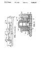
- FIG. 2is a diagrammatic illustration, at least partially in section, of a portion of a control panel including an illuminated dome switch arrangement designed in accordance with the present invention
- FIG. 3is a plan view of the underside of a keycap forming part of the illuminated dome switch illustrated in FIG. 3;
- FIG. 4diagrammatically illustrates an operating feature of the dome switch of FIG. 3;
- FIG. 5is a diagrammatic view, at least partially in section, of an illuminated dome switch designed in accordance with a further embodiment of the present invention.
- FIG. 6is an exploded perspective view of illuminated dome switch arrangements designed in accordance with still further embodiments of the present invention.
- FIG. 2illustrates an illuminated dome switch which is designed in accordance with the present invention and which is generally indicated by the reference numeral 32.
- This switchis shown supported on the base 34 of a printed circuit board 36 which, like all printed circuit boards, includes suitable circuitry for interconnecting its various components.
- This circuit boardis shown forming part of an overall control panel 38 which, itself, may be part of an overall data or video recorder or other such apparatus.
- Illuminated dome switch 32is shown in FIG. 2 including a light source 40 supported on base 34 of printed circuit board 36 and suitably connected in circuit with the latter.
- Light source 40can be an incandescent lamp, an LED, or the like.
- dome 42Located to one side of light source 40 is a dome 42 which corresponds functionally to dome 18 described in conjunction with FIG. 1.
- Dome 42is also supported on the base 34 of printed circuit board 36 and, like light source 40, it is suitably connected in circuit with the PC board. Like the light source, dome 42 forms part of overall dome switch 32.
- dome switch 32also includes a keycap 44 defined primarily by a hollow main body 46 having an uppermost finger depressing portion 48.
- the entire keycapis preferably constructed of a relatively rigid plastic material and at least its upper portion 48 is either light transparent or at least light translucent.
- the main body 46 of keycap 44includes a downwardly facing outermost periphery 50 (see FIG. 3) from which depend two rigid or relatively rigid leg members 52 and 54.
- leg members 52 and 54which are preferably integrally formed as part of the overall keycap, serve as a dome actuator and fulcrum, respectively, in accordance with the present invention, as will be explained.
- Keycap 44is shown positioned directly over light source 40 so that its leg member 52 rests immediately above the center of dome 42 while leg member 54 resides on the opposite side of the light source directly over base 34 of pc board 36.
- a resilient boot 56constructed of, for example, rubber and consisting of a number of different interconnecting sections, is disposed between the light source 40 and keycap body 46, between the underside of leg member 52 and the top surface of dome 42, and, finally, between the underside of leg member 54 and the base 34 of pc board 36.
- Boot 56supports the keycap 44 for movement between a biased raised position, as shown in FIG. 2, and a depressed position, which will be described hereinafter.
- the keycapis contained within a panel facia 58 with a suitable resilient gasket 60 positioned therebetween.
- boot 56supports it in the undepressed position illustrated in FIG. 2.
- the undersides of leg members 52 and 54just barely engage the top sides of the underlying boot sections shown in FIG. 2.
- the two leg members 52 and 54are caused to move downward against their underlying boot sections, causing the latter to deform, thereby depressing dome 42 and ultimately closing its circuit in the manner described previously in conjunction with FIG. 1.
- leg member 52extends up from base 34.
- leg member or actuator 52engages the top of the dome before leg member or fulcrum 54 reaches base 34. This causes the actuator to initially pivot in the manner indicated by arrow A1.
- leg member 54reaches base 34 and then serves as a fulcrum.
- leg member 52in order to depress the dome, actually must move downward further than the leg member 54, although this is not perceptible by the naked eye.
- leg member 52In order for this to happen, once leg member 52 reaches the top of dome 42, leg member 54 is made to serve as a fulcrum pivoting in the manner indicated by arrow A2. In this way leg member 52 serves as an actuator against dome 42 in the same manner as previously described actuator 24. Indeed, because of this relationship between fulcrum 54 and actuator 52, actuation of dome 42 has been found to be just as reliable as actuation of dome 18 even though dome 42 is located to one side of keycap 44 rather than directly under it, as in the case of dome 18 and keycap 22. Obviously the exact ways in which the actuator and fulcrum pivot will depend on where keycap 44 is depressed.
- keycap 44has been described including an actuator 52 and one fulcrum 54.
- the keycapincludes a pair of additional fulcrums 62 and 64 depending from the downwardly facing outer periphery 50 of the keycap, on opposite sides of the periphery between actuator 52 and fulcrum 54.
- additional fulcrumshelp ensure that dome 42 will be appropriately actuated when the keycap is depressed.
- These additional keycapsare especially desirable where the keycap (including the actuator and fulcrums) are constructed of silicone, rubber or like resilient material, as will be described with FIG. 5.
- boot sections between actuator 52 and dome 42may be eliminated so that the actuator engages directly against the dome.
- boot section between fulcrum 54 and base 34 of pc board 36may be eliminated so that the fulcrum can engage directly against the pc board.
- FIG. 5a modified dome switch is illustrated.
- This switchmay include the same pc board 36, light source 40, dome 42 and panel facia 58 as illustrated in FIG. 2.
- its keycap 68is constructed of a semiresilient material, for example, silicone rubber, and an inner boot has been entirely eliminated. Rather, the keycap itself is sufficiently resilient to move between a biased non-actuating position and a depressed position but sufficiently rigid to actuate dome 42.
- the keycapincludes a downwardly depending actuator 70 resting directly on top of dome 42 and a downwardly depending fulcrum 72 (or three such fulcrums) resting against the top surface of printed circuit board 36.
- keycap 68is constructed of a resilient material and does not require an internal boot, it may be identical in design to keycap 44.
- Dome switch 74includes a keycap 78 containing three centrally located lights generally indicated at 80A, 80B and 80C.
- Dome switch 76includes a keycap 82 containing two centrally located lights 84A and 84B. Both dome switches include domes to one side as in the other embodiments and similar actuators and fulcrums.
Landscapes
- Push-Button Switches (AREA)
Abstract
Description
Claims (13)
Priority Applications (1)
| Application Number | Priority Date | Filing Date | Title |
|---|---|---|---|
| US07/866,694US5285037A (en) | 1992-04-10 | 1992-04-10 | Illuminated dome switch |
Applications Claiming Priority (1)
| Application Number | Priority Date | Filing Date | Title |
|---|---|---|---|
| US07/866,694US5285037A (en) | 1992-04-10 | 1992-04-10 | Illuminated dome switch |
Publications (1)
| Publication Number | Publication Date |
|---|---|
| US5285037Atrue US5285037A (en) | 1994-02-08 |
Family
ID=25348189
Family Applications (1)
| Application Number | Title | Priority Date | Filing Date |
|---|---|---|---|
| US07/866,694Expired - Fee RelatedUS5285037A (en) | 1992-04-10 | 1992-04-10 | Illuminated dome switch |
Country Status (1)
| Country | Link |
|---|---|
| US (1) | US5285037A (en) |
Cited By (30)
| Publication number | Priority date | Publication date | Assignee | Title |
|---|---|---|---|---|
| US5708428A (en)* | 1996-12-10 | 1998-01-13 | Ericsson Inc. | Method and apparatus for providing backlighting for keypads and LCD panels |
| US5844203A (en)* | 1995-10-06 | 1998-12-01 | Black & Decker Inc. | Combined switch actuator and signal light transmitter for an iron |
| US5941372A (en)* | 1998-11-12 | 1999-08-24 | Dresser Industries, Inc. | Push button switching system and method |
| US20050145468A1 (en)* | 2003-08-26 | 2005-07-07 | Kim Jae M. | Control panel assembly and method for controlling thereof |
| US20050150753A1 (en)* | 2004-01-12 | 2005-07-14 | Chih-Min Hsu | Key structure and manufacturing method thereof |
| US20050194241A1 (en)* | 2004-03-05 | 2005-09-08 | Lg Electronics Inc. | Button assembly for home appliance |
| US20060237294A1 (en)* | 2005-04-21 | 2006-10-26 | Greer Donald J | Switchpad for a pushbutton switch assembly |
| US7498538B1 (en) | 2007-07-20 | 2009-03-03 | Judco Manufacturing, Inc. | Sliding contact switch |
| US7514643B1 (en) | 2005-07-19 | 2009-04-07 | Judco Manufacturing, Inc. | Lighted pushbutton switch assembly |
| US20090127084A1 (en)* | 2007-11-16 | 2009-05-21 | Dell Products L.P. | Illuminated Indicator On An Input Device |
| US20100025214A1 (en)* | 2008-07-31 | 2010-02-04 | Electrolux Home Products | Unitized Appliance Control Panel Assembly and Components of the Assembly |
| US20100078303A1 (en)* | 2008-09-29 | 2010-04-01 | Microsoft Corporation | Mechanical architecture for display keyboard keys |
| US20100148999A1 (en)* | 2008-12-16 | 2010-06-17 | Casparian Mark A | Keyboard with user configurable granularity scales for pressure sensitive keys |
| US20100214135A1 (en)* | 2009-02-26 | 2010-08-26 | Microsoft Corporation | Dynamic rear-projected user interface |
| US20100288607A1 (en)* | 2007-11-16 | 2010-11-18 | Dell Products L.P. | Illuminated indicator on an input device |
| US20100321301A1 (en)* | 2008-12-16 | 2010-12-23 | Casparian Mark A | Systems and methods for implementing pressure sensitive keyboards |
| US7880107B1 (en) | 2007-10-12 | 2011-02-01 | Judco Manufacturing, Inc. | Momentary push button switch |
| US20110095877A1 (en)* | 2008-12-16 | 2011-04-28 | Casparian Mark A | Apparatus and methods for mounting haptics actuation circuitry in keyboards |
| US8700829B2 (en) | 2011-09-14 | 2014-04-15 | Dell Products, Lp | Systems and methods for implementing a multi-function mode for pressure sensitive sensors and keyboards |
| US8748767B2 (en) | 2011-05-27 | 2014-06-10 | Dell Products Lp | Sub-membrane keycap indicator |
| US9111005B1 (en) | 2014-03-13 | 2015-08-18 | Dell Products Lp | Systems and methods for configuring and controlling variable pressure and variable displacement sensor operations for information handling systems |
| US9343248B2 (en) | 2013-08-29 | 2016-05-17 | Dell Products Lp | Systems and methods for implementing spring loaded mechanical key switches with variable displacement sensing |
| US9342149B2 (en) | 2008-12-16 | 2016-05-17 | Dell Products Lp | Systems and methods for implementing haptics for pressure sensitive keyboards |
| US9368300B2 (en) | 2013-08-29 | 2016-06-14 | Dell Products Lp | Systems and methods for lighting spring loaded mechanical key switches |
| US9384916B1 (en)* | 2013-10-11 | 2016-07-05 | Google Inc. | Keycap with multi-character display |
| US11017964B2 (en)* | 2017-09-01 | 2021-05-25 | Dongguan City Kaihua Electronics Co., Ltd | Middle illuminated button switch |
| US11107648B2 (en)* | 2019-05-28 | 2021-08-31 | Google Llc | Button with illumination ring |
| US11354995B2 (en)* | 2017-07-10 | 2022-06-07 | Carrier Corporation | Hazard detector with optical status indicator |
| US20220261035A1 (en)* | 2009-08-17 | 2022-08-18 | Apple Inc. | Housing as an I/O Device |
| US12094326B2 (en) | 2018-03-30 | 2024-09-17 | Carrier Corporation | Lens for a visual alarm detector |
Citations (9)
| Publication number | Priority date | Publication date | Assignee | Title |
|---|---|---|---|---|
| US4056701A (en)* | 1976-07-08 | 1977-11-01 | Bowmar Instrument Corporation | Low profile lighted push button switch |
| US4245138A (en)* | 1978-11-17 | 1981-01-13 | Rogers Corporation | Tactile element and keyboard including the tactile element |
| US4376879A (en)* | 1980-10-28 | 1983-03-15 | Japan Aviation Electronics Industry Limited | Button-less push switch boards |
| US4423294A (en)* | 1982-06-17 | 1983-12-27 | The Hall Company | Laminate switch assembly having improved durability |
| US4531034A (en)* | 1983-03-24 | 1985-07-23 | Nitsuko Limited | Key switch devices with indicator lamp means |
| US4710597A (en)* | 1984-06-26 | 1987-12-01 | Tabur Caoutchouc | Keyboard for the control box of an electric apparatus |
| US4772769A (en)* | 1987-02-06 | 1988-09-20 | Burr-Brown Corporation | Apparatus for selective backlighting of keys of a keyboard |
| US4885443A (en)* | 1988-11-29 | 1989-12-05 | Tokheim Corporation | Sealed backlit switch assembly |
| US5081329A (en)* | 1990-09-13 | 1992-01-14 | Tie Communications, Inc. | Key assembly, switch assembly and method of making same |
- 1992
- 1992-04-10USUS07/866,694patent/US5285037A/ennot_activeExpired - Fee Related
Patent Citations (9)
| Publication number | Priority date | Publication date | Assignee | Title |
|---|---|---|---|---|
| US4056701A (en)* | 1976-07-08 | 1977-11-01 | Bowmar Instrument Corporation | Low profile lighted push button switch |
| US4245138A (en)* | 1978-11-17 | 1981-01-13 | Rogers Corporation | Tactile element and keyboard including the tactile element |
| US4376879A (en)* | 1980-10-28 | 1983-03-15 | Japan Aviation Electronics Industry Limited | Button-less push switch boards |
| US4423294A (en)* | 1982-06-17 | 1983-12-27 | The Hall Company | Laminate switch assembly having improved durability |
| US4531034A (en)* | 1983-03-24 | 1985-07-23 | Nitsuko Limited | Key switch devices with indicator lamp means |
| US4710597A (en)* | 1984-06-26 | 1987-12-01 | Tabur Caoutchouc | Keyboard for the control box of an electric apparatus |
| US4772769A (en)* | 1987-02-06 | 1988-09-20 | Burr-Brown Corporation | Apparatus for selective backlighting of keys of a keyboard |
| US4885443A (en)* | 1988-11-29 | 1989-12-05 | Tokheim Corporation | Sealed backlit switch assembly |
| US5081329A (en)* | 1990-09-13 | 1992-01-14 | Tie Communications, Inc. | Key assembly, switch assembly and method of making same |
Cited By (50)
| Publication number | Priority date | Publication date | Assignee | Title |
|---|---|---|---|---|
| US5844203A (en)* | 1995-10-06 | 1998-12-01 | Black & Decker Inc. | Combined switch actuator and signal light transmitter for an iron |
| US5708428A (en)* | 1996-12-10 | 1998-01-13 | Ericsson Inc. | Method and apparatus for providing backlighting for keypads and LCD panels |
| US5941372A (en)* | 1998-11-12 | 1999-08-24 | Dresser Industries, Inc. | Push button switching system and method |
| US7394033B2 (en)* | 2003-08-26 | 2008-07-01 | Lg Electronics Inc. | Control panel assembly and method for controlling thereof |
| US20050145468A1 (en)* | 2003-08-26 | 2005-07-07 | Kim Jae M. | Control panel assembly and method for controlling thereof |
| US7915552B2 (en) | 2003-08-26 | 2011-03-29 | Lg Electronics Inc. | Control panel assembly and method for controlling thereof |
| US20080232087A1 (en)* | 2003-08-26 | 2008-09-25 | Jae Mun Kim | Control panel assembly and method for controlling thereof |
| US20050150753A1 (en)* | 2004-01-12 | 2005-07-14 | Chih-Min Hsu | Key structure and manufacturing method thereof |
| US20050194241A1 (en)* | 2004-03-05 | 2005-09-08 | Lg Electronics Inc. | Button assembly for home appliance |
| US7244898B2 (en)* | 2004-03-05 | 2007-07-17 | Lg Electronics Inc. | Button assembly for home appliance |
| US7132615B1 (en)* | 2005-04-21 | 2006-11-07 | Delphi Technologies, Inc. | Switchpad for a pushbutton switch assembly |
| US20060237294A1 (en)* | 2005-04-21 | 2006-10-26 | Greer Donald J | Switchpad for a pushbutton switch assembly |
| US7514643B1 (en) | 2005-07-19 | 2009-04-07 | Judco Manufacturing, Inc. | Lighted pushbutton switch assembly |
| US7498538B1 (en) | 2007-07-20 | 2009-03-03 | Judco Manufacturing, Inc. | Sliding contact switch |
| US7880107B1 (en) | 2007-10-12 | 2011-02-01 | Judco Manufacturing, Inc. | Momentary push button switch |
| US20090127084A1 (en)* | 2007-11-16 | 2009-05-21 | Dell Products L.P. | Illuminated Indicator On An Input Device |
| US8253048B2 (en) | 2007-11-16 | 2012-08-28 | Dell Products L.P. | Illuminated indicator on an input device |
| US7786395B2 (en)* | 2007-11-16 | 2010-08-31 | Dell Products L.P. | Illuminated indicator on an input device |
| US20100288607A1 (en)* | 2007-11-16 | 2010-11-18 | Dell Products L.P. | Illuminated indicator on an input device |
| US20100025214A1 (en)* | 2008-07-31 | 2010-02-04 | Electrolux Home Products | Unitized Appliance Control Panel Assembly and Components of the Assembly |
| US8178802B2 (en) | 2008-07-31 | 2012-05-15 | Electrolux Home Products, Inc. | Unitized appliance control panel assembly and components of the assembly |
| US7982149B2 (en)* | 2008-09-29 | 2011-07-19 | Microsoft Corporation | Mechanical architecture for display keyboard keys |
| US20100078303A1 (en)* | 2008-09-29 | 2010-04-01 | Microsoft Corporation | Mechanical architecture for display keyboard keys |
| US8760273B2 (en) | 2008-12-16 | 2014-06-24 | Dell Products, Lp | Apparatus and methods for mounting haptics actuation circuitry in keyboards |
| US9791941B2 (en) | 2008-12-16 | 2017-10-17 | Dell Products Lp | Keyboard with user configurable granularity scales for pressure sensitive keys |
| US20100148999A1 (en)* | 2008-12-16 | 2010-06-17 | Casparian Mark A | Keyboard with user configurable granularity scales for pressure sensitive keys |
| US20110095877A1 (en)* | 2008-12-16 | 2011-04-28 | Casparian Mark A | Apparatus and methods for mounting haptics actuation circuitry in keyboards |
| US20100321301A1 (en)* | 2008-12-16 | 2010-12-23 | Casparian Mark A | Systems and methods for implementing pressure sensitive keyboards |
| US8711011B2 (en) | 2008-12-16 | 2014-04-29 | Dell Products, Lp | Systems and methods for implementing pressure sensitive keyboards |
| US9342149B2 (en) | 2008-12-16 | 2016-05-17 | Dell Products Lp | Systems and methods for implementing haptics for pressure sensitive keyboards |
| US9246487B2 (en) | 2008-12-16 | 2016-01-26 | Dell Products Lp | Keyboard with user configurable granularity scales for pressure sensitive keys |
| US20100214135A1 (en)* | 2009-02-26 | 2010-08-26 | Microsoft Corporation | Dynamic rear-projected user interface |
| US12105557B2 (en) | 2009-08-17 | 2024-10-01 | Apple Inc. | Housing as an I/O device |
| US11644865B2 (en)* | 2009-08-17 | 2023-05-09 | Apple Inc. | Housing as an I/O device |
| US20220261035A1 (en)* | 2009-08-17 | 2022-08-18 | Apple Inc. | Housing as an I/O Device |
| US8748767B2 (en) | 2011-05-27 | 2014-06-10 | Dell Products Lp | Sub-membrane keycap indicator |
| US8890013B2 (en) | 2011-05-27 | 2014-11-18 | Dell Products Lp | Sub-membrane keycap indicator |
| US8700829B2 (en) | 2011-09-14 | 2014-04-15 | Dell Products, Lp | Systems and methods for implementing a multi-function mode for pressure sensitive sensors and keyboards |
| US9368300B2 (en) | 2013-08-29 | 2016-06-14 | Dell Products Lp | Systems and methods for lighting spring loaded mechanical key switches |
| US9959996B2 (en) | 2013-08-29 | 2018-05-01 | Dell Products Lp | Systems and methods for lighting spring loaded mechanical key switches |
| US9343248B2 (en) | 2013-08-29 | 2016-05-17 | Dell Products Lp | Systems and methods for implementing spring loaded mechanical key switches with variable displacement sensing |
| US9384916B1 (en)* | 2013-10-11 | 2016-07-05 | Google Inc. | Keycap with multi-character display |
| US9111005B1 (en) | 2014-03-13 | 2015-08-18 | Dell Products Lp | Systems and methods for configuring and controlling variable pressure and variable displacement sensor operations for information handling systems |
| US11354995B2 (en)* | 2017-07-10 | 2022-06-07 | Carrier Corporation | Hazard detector with optical status indicator |
| US20220277634A1 (en)* | 2017-07-10 | 2022-09-01 | Carrier Corporation | Hazard detector with optical status indicator |
| US11887451B2 (en)* | 2017-07-10 | 2024-01-30 | Carrier Corporation | Hazard detector with optical status indicator |
| US11017964B2 (en)* | 2017-09-01 | 2021-05-25 | Dongguan City Kaihua Electronics Co., Ltd | Middle illuminated button switch |
| US12094326B2 (en) | 2018-03-30 | 2024-09-17 | Carrier Corporation | Lens for a visual alarm detector |
| US11107648B2 (en)* | 2019-05-28 | 2021-08-31 | Google Llc | Button with illumination ring |
| US11404226B2 (en)* | 2019-05-28 | 2022-08-02 | Google Llc | Button with illumination ring |
Similar Documents
| Publication | Publication Date | Title |
|---|---|---|
| US5285037A (en) | Illuminated dome switch | |
| US6765503B1 (en) | Backlighting for computer keyboard | |
| US6322229B1 (en) | Backlighting for computer keyboard | |
| EP1389790B1 (en) | Illumination structure for pushbutton and electronic device with pushbutton having illumination structure | |
| US4163883A (en) | Keyboard with illuminated keys | |
| US4056701A (en) | Low profile lighted push button switch | |
| US4163138A (en) | Flush lighted flat keyboard assembly | |
| US5747756A (en) | Electroluminescent backlit keypad | |
| US4449024A (en) | Backlighted illuminated keyboard | |
| US4365120A (en) | Illuminated keyboard | |
| US4445164A (en) | Lighted key module assembly | |
| US6609805B1 (en) | Illuminated keyboard | |
| US6743993B1 (en) | Backlit full travel key assembly | |
| US4320268A (en) | Illuminated keyboard for electronic devices and the like | |
| US4225766A (en) | Touch contact | |
| US6299320B1 (en) | Illuminated switch unit | |
| US4002873A (en) | Illuminated pushbutton switch | |
| JPH0122195Y2 (en) | ||
| JP3576718B2 (en) | Switch device | |
| TWI885859B (en) | Illuminated keyswitch | |
| JPH0877867A (en) | Illumination type push-button switch | |
| KR100891480B1 (en) | Switch fastening structure for keyboard | |
| JP3341231B2 (en) | Illuminated switch mechanism | |
| JP2010129261A (en) | Illumination structure of operation button, and control unit equipped with the same | |
| JP3718974B2 (en) | Electronic musical instrument keyboard device |
Legal Events
| Date | Code | Title | Description |
|---|---|---|---|
| AS | Assignment | Owner name:AMPEX CORPORATION A CORPORATION OF CA, CALIFORN Free format text:ASSIGNMENT OF ASSIGNORS INTEREST.;ASSIGNORS:BARANSKI, ANTONI S.;LARKINS, DAVID N.;HEATH, THOMAS J.;AND OTHERS;REEL/FRAME:006095/0279;SIGNING DATES FROM 19920406 TO 19920409 Owner name:SQUARE D COMPANY A CORPORATION OF DE, ILLINOIS Free format text:ASSIGNMENT OF ASSIGNORS INTEREST.;ASSIGNORS:BARANSKI, ANTONI S.;LARKINS, DAVID N.;HEATH, THOMAS J.;AND OTHERS;REEL/FRAME:006095/0279;SIGNING DATES FROM 19920406 TO 19920409 | |
| AS | Assignment | Owner name:AMPEX SYSTEMS CORPORATION A DE CORP., CALIFORNIA Free format text:ASSIGNMENT OF ASSIGNORS INTEREST.;ASSIGNOR:AMPEX CORPORATION A CORPORATION OF CALIFORNIA;REEL/FRAME:006334/0371 Effective date:19920724 | |
| AS | Assignment | Owner name:DEP ACQUISITION CORP., COLORADO Free format text:ASSIGNMENT OF ASSIGNORS INTEREST.;ASSIGNOR:SQUARE D COMPANY;REEL/FRAME:006442/0492 Effective date:19920706 | |
| AS | Assignment | Owner name:DATA ENTRY PRODUCTS, INC., COLORADO Free format text:ASSIGNMENT OF ASSIGNORS INTEREST.;ASSIGNOR:DEP ACQUISITION CORP.;REEL/FRAME:006441/0001 Effective date:19920707 | |
| AS | Assignment | Owner name:DATA ENTRY PRODUCTS, INC., COLORADO Free format text:ASSIGNMENT OF ASSIGNORS INTEREST;ASSIGNOR:SQUARE D. COMPANY, A DE CORP.;REEL/FRAME:006773/0660 Effective date:19931026 | |
| AS | Assignment | Owner name:AMPEX CORPORATION, CALIFORNIA Free format text:ASSIGNMENT OF ASSIGNORS INTEREST;ASSIGNOR:AMPEX SYSTEMS CORPORATION, A DE CORPORATION;REEL/FRAME:007456/0224 Effective date:19950426 | |
| FEPP | Fee payment procedure | Free format text:PAYOR NUMBER ASSIGNED (ORIGINAL EVENT CODE: ASPN); ENTITY STATUS OF PATENT OWNER: LARGE ENTITY | |
| FPAY | Fee payment | Year of fee payment:4 | |
| FPAY | Fee payment | Year of fee payment:8 | |
| REMI | Maintenance fee reminder mailed | ||
| LAPS | Lapse for failure to pay maintenance fees | ||
| STCH | Information on status: patent discontinuation | Free format text:PATENT EXPIRED DUE TO NONPAYMENT OF MAINTENANCE FEES UNDER 37 CFR 1.362 | |
| FP | Lapsed due to failure to pay maintenance fee | Effective date:20060208 |