US5284568A - Disposable cartridge for ion selective electrode sensors - Google Patents
Disposable cartridge for ion selective electrode sensorsDownload PDFInfo
- Publication number
- US5284568A US5284568AUS07/916,231US91623192AUS5284568AUS 5284568 AUS5284568 AUS 5284568AUS 91623192 AUS91623192 AUS 91623192AUS 5284568 AUS5284568 AUS 5284568A
- Authority
- US
- United States
- Prior art keywords
- flow channel
- channel member
- assembly
- substrate
- housing
- Prior art date
- Legal status (The legal status is an assumption and is not a legal conclusion. Google has not performed a legal analysis and makes no representation as to the accuracy of the status listed.)
- Expired - Lifetime
Links
- 239000000758substrateSubstances0.000claimsabstractdescription54
- 239000012530fluidSubstances0.000claimsabstractdescription37
- 239000007788liquidSubstances0.000claimsabstractdescription13
- 239000003153chemical reaction reagentSubstances0.000abstractdescription4
- 229920001971elastomerPolymers0.000abstractdescription4
- 239000000806elastomerSubstances0.000abstractdescription2
- 230000006835compressionEffects0.000abstract1
- 238000007906compressionMethods0.000abstract1
- 238000002347injectionMethods0.000abstract1
- 239000007924injectionSubstances0.000abstract1
- 230000000717retained effectEffects0.000abstract1
- 150000002500ionsChemical class0.000description15
- 239000000523sampleSubstances0.000description14
- 238000005259measurementMethods0.000description10
- 239000000463materialSubstances0.000description7
- -1calibratorsSubstances0.000description6
- 238000013461designMethods0.000description5
- 239000012528membraneSubstances0.000description5
- 239000002699waste materialSubstances0.000description4
- 239000007787solidSubstances0.000description3
- 239000004698PolyethyleneSubstances0.000description2
- 239000004793PolystyreneSubstances0.000description2
- BQCADISMDOOEFD-UHFFFAOYSA-NSilverChemical compound[Ag]BQCADISMDOOEFD-UHFFFAOYSA-N0.000description2
- PNEYBMLMFCGWSK-UHFFFAOYSA-Naluminium oxideInorganic materials[O-2].[O-2].[O-2].[Al+3].[Al+3]PNEYBMLMFCGWSK-UHFFFAOYSA-N0.000description2
- 239000012482calibration solutionSubstances0.000description2
- 238000010276constructionMethods0.000description2
- 239000003792electrolyteSubstances0.000description2
- 238000012423maintenanceMethods0.000description2
- 238000004519manufacturing processMethods0.000description2
- 229910052751metalInorganic materials0.000description2
- 239000002184metalSubstances0.000description2
- 239000004417polycarbonateSubstances0.000description2
- 229920000515polycarbonatePolymers0.000description2
- 229920000573polyethylenePolymers0.000description2
- 229920002223polystyrenePolymers0.000description2
- 238000005086pumpingMethods0.000description2
- 229910052709silverInorganic materials0.000description2
- 239000004332silverSubstances0.000description2
- 239000000243solutionSubstances0.000description2
- VEXZGXHMUGYJMC-UHFFFAOYSA-MChloride anionChemical compound[Cl-]VEXZGXHMUGYJMC-UHFFFAOYSA-M0.000description1
- 206010053567CoagulopathiesDiseases0.000description1
- 239000004593EpoxySubstances0.000description1
- DGAQECJNVWCQMB-PUAWFVPOSA-MIlexoside XXIXChemical compoundC[C@@H]1CC[C@@]2(CC[C@@]3(C(=CC[C@H]4[C@]3(CC[C@@H]5[C@@]4(CC[C@@H](C5(C)C)OS(=O)(=O)[O-])C)C)[C@@H]2[C@]1(C)O)C)C(=O)O[C@H]6[C@@H]([C@H]([C@@H]([C@H](O6)CO)O)O)O.[Na+]DGAQECJNVWCQMB-PUAWFVPOSA-M0.000description1
- 229930040373ParaformaldehydeNatural products0.000description1
- 239000004642PolyimideSubstances0.000description1
- 239000004743PolypropyleneSubstances0.000description1
- ZLMJMSJWJFRBEC-UHFFFAOYSA-NPotassiumChemical compound[K]ZLMJMSJWJFRBEC-UHFFFAOYSA-N0.000description1
- 239000012491analyteSubstances0.000description1
- 238000005452bendingMethods0.000description1
- 229920005557bromobutylPolymers0.000description1
- 229920005549butyl rubberPolymers0.000description1
- 230000035602clottingEffects0.000description1
- 230000015271coagulationEffects0.000description1
- 238000005345coagulationMethods0.000description1
- 239000002131composite materialSubstances0.000description1
- 239000004020conductorSubstances0.000description1
- 239000000470constituentSubstances0.000description1
- 238000010586diagramMethods0.000description1
- 238000005516engineering processMethods0.000description1
- 239000007789gasSubstances0.000description1
- 239000011521glassSubstances0.000description1
- 229920005555halobutylPolymers0.000description1
- 125000004968halobutyl groupChemical group0.000description1
- 239000002555ionophoreSubstances0.000description1
- 230000000236ionophoric effectEffects0.000description1
- 239000002207metaboliteSubstances0.000description1
- 238000000034methodMethods0.000description1
- 238000000465mouldingMethods0.000description1
- 239000000615nonconductorSubstances0.000description1
- 231100000572poisoningToxicity0.000description1
- 230000000607poisoning effectEffects0.000description1
- 229920000728polyesterPolymers0.000description1
- 229920001721polyimidePolymers0.000description1
- 229920006324polyoxymethylenePolymers0.000description1
- 229920001155polypropylenePolymers0.000description1
- 229920001296polysiloxanePolymers0.000description1
- 229920002635polyurethanePolymers0.000description1
- 239000004814polyurethaneSubstances0.000description1
- 229920000915polyvinyl chloridePolymers0.000description1
- 239000004800polyvinyl chlorideSubstances0.000description1
- 229910052700potassiumInorganic materials0.000description1
- 239000011591potassiumSubstances0.000description1
- 102000004169proteins and genesHuman genes0.000description1
- 108090000623proteins and genesProteins0.000description1
- 239000013074reference sampleSubstances0.000description1
- 239000012488sample solutionSubstances0.000description1
- 238000005070samplingMethods0.000description1
- 238000007650screen-printingMethods0.000description1
- 229910052708sodiumInorganic materials0.000description1
- 239000011734sodiumSubstances0.000description1
- 238000012360testing methodMethods0.000description1
- 239000012815thermoplastic materialSubstances0.000description1
Images


Classifications
- G—PHYSICS
- G01—MEASURING; TESTING
- G01N—INVESTIGATING OR ANALYSING MATERIALS BY DETERMINING THEIR CHEMICAL OR PHYSICAL PROPERTIES
- G01N27/00—Investigating or analysing materials by the use of electric, electrochemical, or magnetic means
- G01N27/26—Investigating or analysing materials by the use of electric, electrochemical, or magnetic means by investigating electrochemical variables; by using electrolysis or electrophoresis
- G01N27/403—Cells and electrode assemblies
Definitions
- This inventionrelates to a disposable cartridge for use with ion selective electrode sensors and more particularly to an ion selective electrode assembly positioned in a cartridge which can be readily replaced.
- ion selective electrodeshave routinely been applied in the clinical measurement of sodium, potassium, chloride and similar ions.
- Most ion selective devices on the market todayhave a limited lifetime in the sense that the materials of construction tend to deteriorate with use and time. For example, flow conduits become coated and clogged due to clotting, or coagulation, of protein. Also the ion sensing membranes tend to degrade in performance with time due to membrane poisoning by sample constituents or general loss of ionophore potency.
- Such electrodestypically require a high degree of maintenance. It is desirable, therefore, to be able to replace the ion selective electrodes simply and conveniently with a low cost assembly before performance deteriorates when the occasion or need arises. This is preferable to the substantial maintenance that would be otherwise required to achieve high operating efficiency and effectiveness.
- Disposable solid state sensorspossess significant advantages over ion selective electrodes of conventional design. The ability to discard the sensor after each or several uses is highly desirable. A number of the sensor designs described in the prior art have sought to achieve this end result.
- U.S. Pat. No. 4,994,167issued to Schults et al., discloses a device in which a removable cartridge protects a membrane of an electrode assembly.
- the designdoes not define flow channels and also does not provide a particularly good seal, thus the unit is incapable of being used for analyzing multiple ions.
- U.S. Pat. No. 4,786,394 Enzer et al.disclose a clinical analyzer which comprises a disposable cartridge containing sensors and further describes an electrically connected plug-in contained within the disposable cartridge, described previously, which contains bags for reagents, calibrators, waste dispose, etc.
- the inventionis a disposable cartridge or sensor assembly for use in an analyzer, said assembly comprising: a substrate having a face with a reference element and plural sensor elements formed thereon, an electrical contact positioned on the substrate face for each element, a flow channel member having first and second opposed faces, the first face defining a pair of grooves positioned respectively over the substrate reference and sensor elements and joined together at one end of each groove, thereby defining liquid flow channels, the flow channel member defining orifices interconnecting the opposed faces at the one groove end and at each other groove end, and a housing having a wall and means for holding the substrate relative to the wall to compress the flow channel member therebetween, whereby the liquid flow channels are leak free, the wall defining ports for providing access to the flow channel member orifices and the substrate electrical contacts, said analyzer having a receptacle to removably receive the assembly, electrical connectors to operatively engage
- the flow channel memberis elastomeric and the flow channel member second face has ribs transversely disposed relative to the defined channels for maintaining the integrity of the channels.
- the housing holding meansincludes side walls on the housing, the walls having snaps positioned to retain the substrate.
- the flow channel member second facedefines a cavity and the housing walls have ribs positioned to engage the cavity, thereby to position the flow channel member in the housing.
- the disposable assembly describedis a low cost assembly that can be easily replaced.
- the assemblyis relatively leak free.
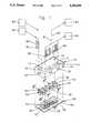
- FIG. 1is an exploded view of the sensor cartridge with fluid and electrical connections as viewed from the top;
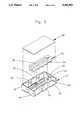
- FIG. 2is an exploded view of the sensor cartridge as viewed from the bottom;
- FIG. 3a sectional view of an assembled sensor cartridge taken on line 3--3 in FIG. 1;
- FIG. 4is a sectional view taken of an assembled sensor cartridge on line 4--4 in FIG. 1;
- FIG. 5is a section view taken of an assembled sensor cartridge on line 5--5 in FIG. 1;
- FIG. 6is a schematic diagram of the sensor substrate
- FIG. 7is an exploded view of the sensor cartridge and a portion of the analyzer.
- FIG. 8is a perspective view of the sensor cartridge installed in a portion of the analyzer.
- a disposable sensor assembly or cartridge 1is comprised of a housing 10, a flow channel member 30 and a sensor substrate 50.
- the size of the sensor cartridge 1is such that it can be easily handled by the user and can be inserted into a sensor cartridge receptacle 84 (FIG. 8) of an analyzer of conventional design.
- Such analyzermay include an electrometer for amplifying the differential signals (measuring the potential difference) derived from the reference, sensor and ground elements of the ion sensor substrate, as will be described. The structure and assembly of these components is discussed in detail below.
- the housing 10is boxlike in shape with one side open and is constructed of a material which is chosen to provide sufficient mechanical strength such to maintain the flow channel member 30 and the sensor substrate 50 in alignment and contact. It also must be flexible enough to bend without failure during assembly of the sensor cartridge 1.
- Thermoplastic materialssuch as polyoxymethylene, polyethylene, polypropylene, polycarbonate or polystyrene with room temperature properties of flexural modulus in the range of 650 to 3500 MPa and tensile strength in the range of 14 to 100 MPa are preferred.
- the top 12 of the housing 10has the same geometry as the sensor substrate 50, which will be described. In a preferred embodiment of this invention, the geometry is rectangular. Other configurations such as circular are possible.
- the sensor substrate 50is a multilayer structure. This fabrication is typically accomplished using screen printing technology as described by Pace in U.S. Pat. No. 4,454,007.
- This sensor substrate 50includes a substrate 60 (FIG. 5) which may be a material chosen to be structurally rigid such that it exhibits negligible distortion when pressure is applied to it from the flow channel member, as will be described.
- the substrateshould be an electrical insulator and provide support for layers 62, 64, 66 and 68 of a multilayer ion sensor. Acceptable materials for the substrate 60 are alumina, glass, glass-epoxy composites, polyester, polyethylene, polyimides, polystyrene or polycarbonate with alumina being preferred.
- the sensor substrate 50is created as described by Pace and others using any accepted multilayer ion sensor construction techniques. By way of example, one first deposits a conductor layer 62, then a dielectric layer 64, an interfacial layer 66 and finally the sensor membrane 68. Since these items are all well known in the art, they need not be described further and are fully described, for example, in the Pace patent whose disclosure is incorporated herein by reference.
- the sensing elements 52which are comprised of the layers 62, 64, 66 and 68 (FIG. 5), may generally be disposed in banks or rows of linearly disposed sensor elements 52 (FIG.
- a ground element 54which may be in the form of a printed silver layer or other suitable metal electrode, is formed at the end of the parallel banks of sensor elements 52.
- a bubble sensing element 56which is in the form of an electrically conductive metal electrode of suitable materials such as silver, is provided at the beginning or entrance of each row of sensing elements 52.
- Each of the sensing elements 52, ground element 54 and the bubble sensing element 56are individually connected by electrically conductive paths which extend beyond the dielectric layer 64 to respective electrical contacts 58 which are formed on the top of the substrate 60. These contacts are located outside of the region that will be occupied by the flow channel member 30 which will form channels over the respective sensing elements as will be described. These contacts are positioned so that they may be contacted by electrical connectors 82, as will be described.
- the flow channel member 30is positioned above the sensor substrate 50. It has two faces, the lower face (best seen in FIG. 2) having defined therein a pair of grooves 38, which are spaced so as to be able to cover the respective elements 52, 54 and 56 on the substrate 60, thereby defining flow channels 70.
- the groovesshould be small to reduce the fluid volume required. Typically grooves of 0.5 mm to 4 mm in diameter have been found suitable, although these numbers are not critical.
- the ends of the grooves 38 adjacent the ground element 54 of the substrate 60are brought together to make a common exit point for the channels 70 that are defined by the grooves 38.
- Ports 32are formed transversely through the thickness of the flow channel member 30 and are located such that one port 32 is at the common exit of the grooves and a separate port 32 is at the entrance of each of the grooves 38. This may best be seen in FIG. 1.
- the upper surface of the flow channel memberis provided with support ribs 34 which aids in compressing the flow channel member against the sensor substrates 50, as will be described, to form the channels over the sensing elements without destroying the integrity of the channels 70.
- a rib receptacle 36is provided to engage ribs 16 in the housing 10. These ribs 16 properly locate and position the flow channel member 30 relative to the sensing elements 52 and add to the stiffness of the housing 1.
- the flow channel member 30is formed of a material which is chosen to be chemically inert with respect to solutions likely to be used in the sensor cartridge. Its mechanical properties are such that it remains in a compressive state when assembled in the cartridge 1 and provides a leak-tight seal between it and the sensor substrate 60. It also provides a leak-tight seal between it and the fluid connectors 80.
- Elastomer materialssuch as butyl rubber, halobutyl rubber, bromobutyl rubber, silicone, polyurethane or polyvinyl chloride with room temperatures mechanical properties of hardness in the range of 40 Shore A (ASTM D-2240) to 60 Shore A and a segment modulus at 10% strain in the range 0.7 to 4.2 MPa are preferred.
- the top 12 of the housing 10contains apertures or holes 14 to permit fluid connections and ports or apertures 15 to accommodate electrical connection to the sensor cartridge 1.
- Side walls 18 of the housinghave snaps 20 which protrude to retain the sensor substrate 50 in the sensor cartridge 1 in the embodiment of this invention depicted.
- the side walls 18are independent of each other to facilitate bending during assembly. Portions of the housing side walls may be cut out to accommodate the molding operation as necessary.
- the apertures 15 for the electrical connectorsmay be reinforced on the bottom side of the housing by ribs 25.
- the electrical connectors 82are connected to electronic circuitry 96 which may as needed incorporate a multiplexer and electrometer amplifiers to selectively connect to the various pairs of sensing elements 52, ground elements 54 and bubble sensing element 56 so as to facilitate the various differential and bubble to ground measurements necessary for the operation of the device.
- the outlet of the flow channel 14Cis connected through fluid connector 80C to a waste receptacle 94. Fluid flow may be facilitated by means of a pump (not shown).
- a source of sample fluid 92 to be tested and/or calibrator fluidis coupled through a fluid connector 80a, through port 14a to the sample port 32a of the flow channel member 30 to feed the sensor channel 70a.
- a source of reference fluid 90may be connected through a second fluid.. connector 80b and the reference port I4b to sample port 32b of to the flow channel member 30 to feed the reference channel 70.
- the sensor cartridge 1is assembled by first placing the rib receptacle 36 of the flow channel member 30 over the rib 16 of the housing 10. This positions and defines the location of the flow channel member 30 with respect to the housing 10.
- the sensor substrateis then placed on the tapered portion 22 of the housing side walls 18. This helps to define the location of the sensor substrate 50 with respect to the housing 10, thereby locating the flow channel member 30 to the sensor substrate 50.
- a forceis applied to the sensor substrate 50 manually or by an assembly tool causing the housing side walls 18 to bend outward and the flow channel member 30 to be compressed. After the sensor substrate 50 has been moved passed the snap 20, the housing side walls 18 bend back to their original position.
- the compressive state of the flow channel member 30 between the sensor substrate 50 and the housing 10keeps the sensor cartridge 1 assembled. This compressive state of the flow channel member 30 also maintains the leak-free interface between the flow channel member 30 and the sensor substrate 50. As seen in FIG. 5, when the sensor cartridge 1 is assembled, the groove 38 and the sensor substrate 50 define the flow channels 70a and 70b.
- the sensor cartridge 1is positioned into a sensor cartridge receptacle 84 (FIGS. 7 and 8) of analyzer.
- the analyzerincorporates the source of reference sample and calibrator fluids and contains the waste receptacle and electronic circuitry necessary to make the necessary measurements of the differential voltages across the ion sensitive electrodes. Since reagent containers and sampling devices for supplying these fluids and making these measurements are standard, they need not be described.
- the correct orientation of the cartridge 1is guaranteed by the housing sidewall cutout 24 (FIG. 2) and the protrusion 88 of the sensor cartridge receptacle 84.
- the preferred orientationis such that the electrical connectors 82 are located above the fluid connectors 80a, 80b, and 80c. This arrangement minimizes fluid contact to the electrical connectors 82 if there is leakage from the fluid connectors 80a80b, and 80c.
- the analyzer connector plate 86is then translated to make fluid and electrical connection to the sensor cartridge 1.
- the ports 32a and 32bare expanded when the fluid connectors 80a and 80b are translated into the flow channel member 30, thus creating a leak free interface.
- the tapered ends 81 of the fluid connectors 80a and 80bfacilitates this connection but is not required.
- the electrical connector 82(FIG. 4) contacts the electrical contacts 58 (FIG. 1) of the sensor substrate 50.
- Operation of the sensor cartridge 1consists of a two point calibration and then multiple sample measurements. Both the two point calibration and the sample measurement are comprised of two measurements. Referring to FIGS. 1, 5 and 6, all fluids are drawn into the system by way of a pump (not shown) located preferably on the waste 94 side of the sensor cartridge 1. Flow from the ports 90 and 92 is controlled by pinch valves (not shown). Reference fluids are solutions with known ionic concentrations over the range to be measured.
- the first part of the two point calibrationconsists of drawing a reference fluid by way of the reference port 90 into the flow channel 70b and then drawing the same reference fluid by way of the sample port 92 into the flow channel 70a.
- a potential E i(FIG. 6) is then measured by the electronics 96.
- the second part of the two point calibrationconsists of pumping a different reference fluid by way of the sample port 92 into the flow channel 70a.
- a potential E i (FIG. 6)is then measured by the electronics 96.
- the response or slope of the sensoris calculated from the measured potentials and the known ionic concentrations of the reference fluids determined earlier.
- the first part of the sample measurementconsists of pumping a reference fluid by way of the reference port 90 into the flow channel 70b and then drawing the same reference fluid by way of the sample port 92 into the flow channel 70a.
- a potential E i(FIG. 6) is then measured by the electronics 96.
- the second part of the sample measurementconsists of drawing the sample fluid by way of the sample port 92 into the flow channel 70a.
- a potential E i(FIG. 6) is then measured by the electronics 96.
- the concentration of the ion in the sampleis calculated from the measured potentials and the known slope of the sensor and ionic concentration of the reference fluid.
- Streaming potentials caused by fluid floware minimized by the ground element 54.
- the presence of air bubbles in the flow channel 70a and 70b between the bubble sensing element 56 and the ground element 54can be determined by measuring the impedance Z (FIG. 6) of the fluid between these elements.
- fluidincludes liquids as well as gases, although at the present time liquids are primarily used. Also, although several reference sensor elements are shown, a single element can be used. The sensor elements may be along a curved path if desired.
- the sensor cartridge just describedis seen to provide a low cost, reliable disposable unit that can replace a unit in use whenever or before it fails.
- the unitprovides a leak-free seal with the sensor substrate and leak-free fluidics. It is designed to maintain critically aligned flow paths for providing channels for the sensing elements.
Landscapes
- Chemical & Material Sciences (AREA)
- Life Sciences & Earth Sciences (AREA)
- Health & Medical Sciences (AREA)
- Biochemistry (AREA)
- General Physics & Mathematics (AREA)
- Electrochemistry (AREA)
- Physics & Mathematics (AREA)
- Analytical Chemistry (AREA)
- Molecular Biology (AREA)
- General Health & Medical Sciences (AREA)
- Chemical Kinetics & Catalysis (AREA)
- Immunology (AREA)
- Pathology (AREA)
- Automatic Analysis And Handling Materials Therefor (AREA)
- Investigating Or Analysing Biological Materials (AREA)
- Investigating Or Analyzing Materials By The Use Of Electric Means (AREA)
- Measurement Of The Respiration, Hearing Ability, Form, And Blood Characteristics Of Living Organisms (AREA)
Abstract
Description
Claims (17)
Priority Applications (6)
| Application Number | Priority Date | Filing Date | Title |
|---|---|---|---|
| US07/916,231US5284568A (en) | 1992-07-17 | 1992-07-17 | Disposable cartridge for ion selective electrode sensors |
| DE69316281TDE69316281T2 (en) | 1992-07-17 | 1993-07-02 | Disposable module for a sensor with ion-selective electrodes |
| AT93110588TATE162307T1 (en) | 1992-07-17 | 1993-07-02 | DISPOSABLE MODULE FOR A SENSOR WITH ION SELECTIVE ELECTRODES |
| EP93110588AEP0579997B1 (en) | 1992-07-17 | 1993-07-02 | Disposable cartridge for ion selective electrode sensors |
| CA002100557ACA2100557A1 (en) | 1992-07-17 | 1993-07-14 | Disposable cartridge for ion selective electrode sensors |
| JP5196690AJP2574631B2 (en) | 1992-07-17 | 1993-07-15 | Disposable cartridges for ion-selective electrode sensors |
Applications Claiming Priority (1)
| Application Number | Priority Date | Filing Date | Title |
|---|---|---|---|
| US07/916,231US5284568A (en) | 1992-07-17 | 1992-07-17 | Disposable cartridge for ion selective electrode sensors |
Publications (1)
| Publication Number | Publication Date |
|---|---|
| US5284568Atrue US5284568A (en) | 1994-02-08 |
Family
ID=25436914
Family Applications (1)
| Application Number | Title | Priority Date | Filing Date |
|---|---|---|---|
| US07/916,231Expired - LifetimeUS5284568A (en) | 1992-07-17 | 1992-07-17 | Disposable cartridge for ion selective electrode sensors |
Country Status (6)
| Country | Link |
|---|---|
| US (1) | US5284568A (en) |
| EP (1) | EP0579997B1 (en) |
| JP (1) | JP2574631B2 (en) |
| AT (1) | ATE162307T1 (en) |
| CA (1) | CA2100557A1 (en) |
| DE (1) | DE69316281T2 (en) |
Cited By (34)
| Publication number | Priority date | Publication date | Assignee | Title |
|---|---|---|---|---|
| USD351913S (en) | 1993-02-25 | 1994-10-25 | Diametrics Medical, Inc. | Disposable electrochemical measurement cartridge for a portable medical analyzer |
| US5421983A (en)* | 1993-11-12 | 1995-06-06 | E. I. Du Pont De Nemours And Company | Anion selective electrodes containing fumed silica |
| USD369561S (en) | 1994-06-27 | 1996-05-07 | Ciba Corning Diagnostics Corp. | Electrochemical sensor package |
| US5520787A (en)* | 1994-02-09 | 1996-05-28 | Abbott Laboratories | Diagnostic flow cell device |
| US5522978A (en)* | 1993-11-18 | 1996-06-04 | E. I. Du Pont De Nemours And Company | Monensin amides for sodium-selective electrodes |
| US5582698A (en)* | 1994-06-27 | 1996-12-10 | Ciba Corning Diagnostics Corp. | Sensor package |
| DE19537506C1 (en)* | 1995-09-26 | 1997-03-27 | Ufz Leipzighalle Gmbh | Flow rate measuring cell for biosensor |
| EP0772043A2 (en) | 1995-10-31 | 1997-05-07 | Ciba Corning Diagnostics Corp. | Fluorelastomer gasket for blood analyte sensors |
| WO1997036542A1 (en)* | 1996-03-29 | 1997-10-09 | Willis John P | Improved point-of-care analyzer module |
| WO1997044672A1 (en)* | 1996-05-20 | 1997-11-27 | Sendx Medical, Inc. | Portable modular blood analyzer with simplified fluid handling sequence |
| US5747666A (en)* | 1997-03-26 | 1998-05-05 | Willis; John P. | Point-of-care analyzer module |
| AT403962B (en)* | 1996-10-30 | 1998-07-27 | Avl Verbrennungskraft Messtech | DEVICE FOR CARRYING OUT ELECTROCHEMICAL AND / OR OPTICAL MEASURING PROCEDURES IN LIQUIDS |
| US5885533A (en)* | 1996-05-20 | 1999-03-23 | Sendx Medical, Inc. | Integral fluid and waste container for blood analyzer |
| US5913232A (en)* | 1996-05-20 | 1999-06-15 | Sendx Medical, Inc. | reference solution container for blood gas/electrolyte measuring system |
| US5951837A (en)* | 1996-06-21 | 1999-09-14 | Dade Behring Inc. | Composition and method for manufacturing ion selective electrode sensors |
| US5958201A (en)* | 1996-08-26 | 1999-09-28 | Dade Behring Inc. | Sodium ion-selective-electrode membrane having extended uselife |
| US6126800A (en)* | 1997-06-06 | 2000-10-03 | Commissariat A L'energie Atomique | Micro-system with an integrated cuvette for the analysis of liquids |
| US6368478B1 (en) | 1999-09-21 | 2002-04-09 | F. Hoffmann La Roche Ag | Electrochemical measuring device with an planar sensor substrate |
| DE10050883A1 (en)* | 2000-10-13 | 2002-05-16 | It Dr Gambert Gmbh | Apparatus for determining concentration of ionic components in body fluids, e.g. for medical diagnosis, comprises disposable cassette with electrochemical sensor and contacts which transmit signals to processor |
| US6391175B1 (en) | 2000-11-21 | 2002-05-21 | Dade Behring Inc. | Carbonate ionophore with improved selectivity |
| US6398931B1 (en) | 2000-01-31 | 2002-06-04 | Phoenix Electrode Company | Combination ion-selective electrode with a replaceable sensing membrane |
| USD474410S1 (en) | 1994-06-27 | 2003-05-13 | Bayer Corporation | Sensor package |
| US20030209451A1 (en)* | 2002-03-13 | 2003-11-13 | The Charles Stark Draper Laboratory, Inc. | Microfluidic ion-selective electrode sensor system |
| US6723216B2 (en) | 1999-10-29 | 2004-04-20 | Radiometer Medical A/S | Method and apparatus for detection of a bubble in a liquid |
| US20040238357A1 (en)* | 1999-12-23 | 2004-12-02 | Roche Diagnostics Corporation | Sensor system |
| US20050214881A1 (en)* | 2003-11-10 | 2005-09-29 | Sentec Scientific, Inc. | Device for analyte measurement |
| US20060011493A1 (en)* | 2002-08-23 | 2006-01-19 | Heinz Kontschieder | Method and a device for monitoring a medical microsample in the flow measuring cell of an analyzer |
| US20060098683A1 (en)* | 2004-11-10 | 2006-05-11 | Thaler Patricia A | System and method for auto-negotiation in a data communication device |
| US7189314B1 (en) | 2002-09-06 | 2007-03-13 | Sensicore, Inc. | Method and apparatus for quantitative analysis |
| US8033157B2 (en) | 2007-10-01 | 2011-10-11 | Baxter International Inc. | Medical fluid air bubble detection apparatus and method |
| US20200110123A1 (en)* | 2018-10-04 | 2020-04-09 | Genmark Diagnostics, Inc. | Systems and methods for assessing electrical connectivity between elements of assay devices |
| US20220120774A1 (en)* | 2019-04-26 | 2022-04-21 | Hitachi High-Tech Corporation | Automated analysis device |
| US20220404310A1 (en)* | 2019-07-19 | 2022-12-22 | Hitachi High-Tech Corporation | Analysis device and analysis method |
| US20230195079A1 (en)* | 2021-12-21 | 2023-06-22 | International Business Machines Corporation | Characterizing liquids based on features extracted from time-dependent, differential signal measurements |
Families Citing this family (31)
| Publication number | Priority date | Publication date | Assignee | Title |
|---|---|---|---|---|
| DE19602861C2 (en)* | 1996-01-28 | 1997-12-11 | Meinhard Prof Dr Knoll | Sampling system for analytes contained in carrier liquids and method for its production |
| US6193864B1 (en) | 1996-05-16 | 2001-02-27 | Sendx Medical, Inc. | Locking sensor cartridge with integral fluid ports, electrical connections, and pump tube |
| US5718816A (en)* | 1996-05-16 | 1998-02-17 | Sendx Medical, Inc. | Locking sensor cartridge with integral fluid ports electrical connections, and pump tube |
| SE9602298D0 (en)* | 1996-06-11 | 1996-06-11 | Siemens Elema Ab | Arrangement for analyzing body fluids |
| US5916522A (en)* | 1997-08-07 | 1999-06-29 | Careside, Inc. | Electrochemical analytical cartridge |
| US7875440B2 (en) | 1998-05-01 | 2011-01-25 | Arizona Board Of Regents | Method of determining the nucleotide sequence of oligonucleotides and DNA molecules |
| US6780591B2 (en) | 1998-05-01 | 2004-08-24 | Arizona Board Of Regents | Method of determining the nucleotide sequence of oligonucleotides and DNA molecules |
| US7501245B2 (en) | 1999-06-28 | 2009-03-10 | Helicos Biosciences Corp. | Methods and apparatuses for analyzing polynucleotide sequences |
| US6818395B1 (en) | 1999-06-28 | 2004-11-16 | California Institute Of Technology | Methods and apparatus for analyzing polynucleotide sequences |
| AU2002230524A1 (en) | 2000-11-16 | 2002-05-27 | California Institute Of Technology | Apparatus and methods for conducting assays and high throughput screening |
| CA2440754A1 (en) | 2001-03-12 | 2002-09-19 | Stephen Quake | Methods and apparatus for analyzing polynucleotide sequences by asynchronous base extension |
| AU2002307152A1 (en) | 2001-04-06 | 2002-10-21 | California Institute Of Technology | Nucleic acid amplification utilizing microfluidic devices |
| JP4355210B2 (en) | 2001-11-30 | 2009-10-28 | フルイディグム コーポレイション | Microfluidic device and method of using microfluidic device |
| WO2003085379A2 (en) | 2002-04-01 | 2003-10-16 | Fluidigm Corporation | Microfluidic particle-analysis systems |
| US7312085B2 (en) | 2002-04-01 | 2007-12-25 | Fluidigm Corporation | Microfluidic particle-analysis systems |
| JP2006501056A (en) | 2002-09-25 | 2006-01-12 | カリフォルニア インスティテュート オブ テクノロジー | Micro fluid large scale integration |
| EP1546412B1 (en) | 2002-10-02 | 2014-05-21 | California Institute Of Technology | Microfluidic nucleic acid analysis |
| US7604965B2 (en) | 2003-04-03 | 2009-10-20 | Fluidigm Corporation | Thermal reaction device and method for using the same |
| DE10321568A1 (en)* | 2003-05-14 | 2004-12-02 | Forschungszentrum Karlsruhe Gmbh | Component module for microtechnology especially for manufacturing analysis devices, has two components connected by a stretchable connector |
| US7169560B2 (en) | 2003-11-12 | 2007-01-30 | Helicos Biosciences Corporation | Short cycle methods for sequencing polynucleotides |
| DE602005020421D1 (en) | 2004-02-19 | 2010-05-20 | Helicos Biosciences Corp | METHOD FOR THE ANALYSIS OF POLYNUCLEOTIDE SEQUENCES |
| JP2008512084A (en) | 2004-05-25 | 2008-04-24 | ヘリコス バイオサイエンシーズ コーポレイション | Methods and devices for nucleic acid sequencing |
| US7476734B2 (en) | 2005-12-06 | 2009-01-13 | Helicos Biosciences Corporation | Nucleotide analogs |
| US7220549B2 (en) | 2004-12-30 | 2007-05-22 | Helicos Biosciences Corporation | Stabilizing a nucleic acid for nucleic acid sequencing |
| US7482120B2 (en) | 2005-01-28 | 2009-01-27 | Helicos Biosciences Corporation | Methods and compositions for improving fidelity in a nucleic acid synthesis reaction |
| US7666593B2 (en) | 2005-08-26 | 2010-02-23 | Helicos Biosciences Corporation | Single molecule sequencing of captured nucleic acids |
| US7815868B1 (en) | 2006-02-28 | 2010-10-19 | Fluidigm Corporation | Microfluidic reaction apparatus for high throughput screening |
| US7397546B2 (en) | 2006-03-08 | 2008-07-08 | Helicos Biosciences Corporation | Systems and methods for reducing detected intensity non-uniformity in a laser beam |
| WO2010125518A2 (en)* | 2009-04-27 | 2010-11-04 | E-Vitae Pte. Ltd. | On-chip laboratory for blood analysis |
| EP2825873B1 (en)* | 2012-03-12 | 2016-03-09 | CSEM Centre Suisse d'Electronique et de Microtechnique SA - Recherche et Développement | Disposable system for ion selective electrodes for long term monitoring |
| JP6629063B2 (en)* | 2015-12-14 | 2020-01-15 | 株式会社堀場製作所 | measuring device |
Citations (7)
| Publication number | Priority date | Publication date | Assignee | Title |
|---|---|---|---|---|
| US4786394A (en)* | 1985-08-29 | 1988-11-22 | Diamond Sensor Systems, Inc. | Apparatus for chemical measurement of blood characteristics |
| US4810251A (en)* | 1985-05-17 | 1989-03-07 | Bayer Aktiengesellschaft | Fatliquoring solution dispersion or emulsion and a process for treating leather therewith |
| US4871439A (en)* | 1987-02-05 | 1989-10-03 | Steven Enzer | Disposable self-calibratable electrode package |
| US4933048A (en)* | 1988-02-16 | 1990-06-12 | I-Stat Corporation | Reference electrode, method of making and method of using same |
| US4994167A (en)* | 1986-04-15 | 1991-02-19 | Markwell Medical Institute, Inc. | Biological fluid measuring device |
| US5004583A (en)* | 1987-01-29 | 1991-04-02 | Medtest Systems, Inc. | Universal sensor cartridge for use with a universal analyzer for sensing components in a multicomponent fluid |
| US5018527A (en)* | 1987-08-01 | 1991-05-28 | Siegert Gmbh | Sensor for the measurement of ion activity |
Family Cites Families (6)
| Publication number | Priority date | Publication date | Assignee | Title |
|---|---|---|---|---|
| DE3111190C2 (en)* | 1981-03-21 | 1983-04-07 | Drägerwerk AG, 2400 Lübeck | Electrochemical measuring sensor with exchangeable membrane holder |
| US4618476A (en)* | 1984-02-10 | 1986-10-21 | Eastman Kodak Company | Capillary transport device having speed and meniscus control means |
| GB8720470D0 (en)* | 1987-08-29 | 1987-10-07 | Emi Plc Thorn | Sensor arrangements |
| US5096669A (en)* | 1988-09-15 | 1992-03-17 | I-Stat Corporation | Disposable sensing device for real time fluid analysis |
| US5046496A (en)* | 1989-04-26 | 1991-09-10 | Ppg Industries, Inc. | Sensor assembly for measuring analytes in fluids |
| JPH03127252U (en)* | 1990-04-02 | 1991-12-20 |
- 1992
- 1992-07-17USUS07/916,231patent/US5284568A/ennot_activeExpired - Lifetime
- 1993
- 1993-07-02ATAT93110588Tpatent/ATE162307T1/ennot_activeIP Right Cessation
- 1993-07-02EPEP93110588Apatent/EP0579997B1/ennot_activeExpired - Lifetime
- 1993-07-02DEDE69316281Tpatent/DE69316281T2/ennot_activeExpired - Lifetime
- 1993-07-14CACA002100557Apatent/CA2100557A1/ennot_activeAbandoned
- 1993-07-15JPJP5196690Apatent/JP2574631B2/ennot_activeExpired - Lifetime
Patent Citations (7)
| Publication number | Priority date | Publication date | Assignee | Title |
|---|---|---|---|---|
| US4810251A (en)* | 1985-05-17 | 1989-03-07 | Bayer Aktiengesellschaft | Fatliquoring solution dispersion or emulsion and a process for treating leather therewith |
| US4786394A (en)* | 1985-08-29 | 1988-11-22 | Diamond Sensor Systems, Inc. | Apparatus for chemical measurement of blood characteristics |
| US4994167A (en)* | 1986-04-15 | 1991-02-19 | Markwell Medical Institute, Inc. | Biological fluid measuring device |
| US5004583A (en)* | 1987-01-29 | 1991-04-02 | Medtest Systems, Inc. | Universal sensor cartridge for use with a universal analyzer for sensing components in a multicomponent fluid |
| US4871439A (en)* | 1987-02-05 | 1989-10-03 | Steven Enzer | Disposable self-calibratable electrode package |
| US5018527A (en)* | 1987-08-01 | 1991-05-28 | Siegert Gmbh | Sensor for the measurement of ion activity |
| US4933048A (en)* | 1988-02-16 | 1990-06-12 | I-Stat Corporation | Reference electrode, method of making and method of using same |
Cited By (53)
| Publication number | Priority date | Publication date | Assignee | Title |
|---|---|---|---|---|
| USD351913S (en) | 1993-02-25 | 1994-10-25 | Diametrics Medical, Inc. | Disposable electrochemical measurement cartridge for a portable medical analyzer |
| US5421983A (en)* | 1993-11-12 | 1995-06-06 | E. I. Du Pont De Nemours And Company | Anion selective electrodes containing fumed silica |
| US5522978A (en)* | 1993-11-18 | 1996-06-04 | E. I. Du Pont De Nemours And Company | Monensin amides for sodium-selective electrodes |
| US5520787A (en)* | 1994-02-09 | 1996-05-28 | Abbott Laboratories | Diagnostic flow cell device |
| EP0752099A1 (en)* | 1994-02-09 | 1997-01-08 | Abbott Laboratories | Diagnostic flow cell device |
| JPH09509485A (en)* | 1994-02-09 | 1997-09-22 | アボツト・ラボラトリーズ | Diagnostic flow cell device |
| USD474410S1 (en) | 1994-06-27 | 2003-05-13 | Bayer Corporation | Sensor package |
| USD369561S (en) | 1994-06-27 | 1996-05-07 | Ciba Corning Diagnostics Corp. | Electrochemical sensor package |
| US5582698A (en)* | 1994-06-27 | 1996-12-10 | Ciba Corning Diagnostics Corp. | Sensor package |
| DE19537506C1 (en)* | 1995-09-26 | 1997-03-27 | Ufz Leipzighalle Gmbh | Flow rate measuring cell for biosensor |
| US5700360A (en)* | 1995-10-31 | 1997-12-23 | Chiron Diagnostics Corporation | Fluoroelastomer gasket for blood sensors |
| EP0772043A3 (en)* | 1995-10-31 | 1998-04-22 | Ciba Corning Diagnostics Corp. | Fluorelastomer gasket for blood analyte sensors |
| EP0772043A2 (en) | 1995-10-31 | 1997-05-07 | Ciba Corning Diagnostics Corp. | Fluorelastomer gasket for blood analyte sensors |
| WO1997036542A1 (en)* | 1996-03-29 | 1997-10-09 | Willis John P | Improved point-of-care analyzer module |
| US5980830A (en)* | 1996-05-20 | 1999-11-09 | Sendx Medical, Inc. | Portable modular blood analyzer with simplified fluid handling sequence |
| US6016683A (en)* | 1996-05-20 | 2000-01-25 | Sendx Medical, Inc. | Reference solution container for blood gas/electrolyte measuring system |
| US5885533A (en)* | 1996-05-20 | 1999-03-23 | Sendx Medical, Inc. | Integral fluid and waste container for blood analyzer |
| US5913232A (en)* | 1996-05-20 | 1999-06-15 | Sendx Medical, Inc. | reference solution container for blood gas/electrolyte measuring system |
| WO1997044672A1 (en)* | 1996-05-20 | 1997-11-27 | Sendx Medical, Inc. | Portable modular blood analyzer with simplified fluid handling sequence |
| US5951837A (en)* | 1996-06-21 | 1999-09-14 | Dade Behring Inc. | Composition and method for manufacturing ion selective electrode sensors |
| US5964994A (en)* | 1996-06-21 | 1999-10-12 | Dade Behring Inc. | Composition and method for manufacturing ion selective electrode sensors |
| US5958201A (en)* | 1996-08-26 | 1999-09-28 | Dade Behring Inc. | Sodium ion-selective-electrode membrane having extended uselife |
| US6001228A (en)* | 1996-10-30 | 1999-12-14 | Avl Medical Instruments Ag | Device for performing measurements in fluids |
| AT403962B (en)* | 1996-10-30 | 1998-07-27 | Avl Verbrennungskraft Messtech | DEVICE FOR CARRYING OUT ELECTROCHEMICAL AND / OR OPTICAL MEASURING PROCEDURES IN LIQUIDS |
| EP0846947A3 (en)* | 1996-10-30 | 2000-09-13 | AVL Medical Instruments AG | Apparatus for performing electrochemical and/or optical measurements in liquids |
| US5747666A (en)* | 1997-03-26 | 1998-05-05 | Willis; John P. | Point-of-care analyzer module |
| US6126800A (en)* | 1997-06-06 | 2000-10-03 | Commissariat A L'energie Atomique | Micro-system with an integrated cuvette for the analysis of liquids |
| US6368478B1 (en) | 1999-09-21 | 2002-04-09 | F. Hoffmann La Roche Ag | Electrochemical measuring device with an planar sensor substrate |
| US6723216B2 (en) | 1999-10-29 | 2004-04-20 | Radiometer Medical A/S | Method and apparatus for detection of a bubble in a liquid |
| US20040238357A1 (en)* | 1999-12-23 | 2004-12-02 | Roche Diagnostics Corporation | Sensor system |
| US7510643B2 (en)* | 1999-12-23 | 2009-03-31 | Roche Diagnostics Operations, Inc. | Sensor system |
| US6398931B1 (en) | 2000-01-31 | 2002-06-04 | Phoenix Electrode Company | Combination ion-selective electrode with a replaceable sensing membrane |
| DE10050883A1 (en)* | 2000-10-13 | 2002-05-16 | It Dr Gambert Gmbh | Apparatus for determining concentration of ionic components in body fluids, e.g. for medical diagnosis, comprises disposable cassette with electrochemical sensor and contacts which transmit signals to processor |
| US6391175B1 (en) | 2000-11-21 | 2002-05-21 | Dade Behring Inc. | Carbonate ionophore with improved selectivity |
| US20030209451A1 (en)* | 2002-03-13 | 2003-11-13 | The Charles Stark Draper Laboratory, Inc. | Microfluidic ion-selective electrode sensor system |
| US7101472B2 (en)* | 2002-03-13 | 2006-09-05 | The Charles Stark Draper Laboratory, Inc. | Microfluidic ion-selective electrode sensor system |
| US7297241B2 (en)* | 2002-08-23 | 2007-11-20 | Roche Diagnostics Operations, Inc. | Method and a device for monitoring a medical microsample in the flow measuring cell of an analyzer |
| US20060011493A1 (en)* | 2002-08-23 | 2006-01-19 | Heinz Kontschieder | Method and a device for monitoring a medical microsample in the flow measuring cell of an analyzer |
| US7189314B1 (en) | 2002-09-06 | 2007-03-13 | Sensicore, Inc. | Method and apparatus for quantitative analysis |
| US7378270B2 (en) | 2003-11-10 | 2008-05-27 | Sentec Scientific, Inc. | Device for analyte measurement |
| US20050214881A1 (en)* | 2003-11-10 | 2005-09-29 | Sentec Scientific, Inc. | Device for analyte measurement |
| US20060098683A1 (en)* | 2004-11-10 | 2006-05-11 | Thaler Patricia A | System and method for auto-negotiation in a data communication device |
| US8033157B2 (en) | 2007-10-01 | 2011-10-11 | Baxter International Inc. | Medical fluid air bubble detection apparatus and method |
| US11391790B2 (en) | 2018-10-04 | 2022-07-19 | Roche Molecular Systems, Inc. | Systems and methods for assessing electrical connectivity between elements of assay devices |
| US10753986B2 (en)* | 2018-10-04 | 2020-08-25 | Genmark Diagnostics, Inc. | Systems and methods for assessing electrical connectivity between elements of assay devices |
| US20200110123A1 (en)* | 2018-10-04 | 2020-04-09 | Genmark Diagnostics, Inc. | Systems and methods for assessing electrical connectivity between elements of assay devices |
| US20220365146A1 (en)* | 2018-10-04 | 2022-11-17 | Roche Molecular Systems, Inc. | Systems and methods for assessing electrical connectivity between elements of assay devices |
| US11635475B2 (en)* | 2018-10-04 | 2023-04-25 | Roche Molecular Systems, Inc. | Systems and methods for assessing electrical connectivity between elements of assay devices |
| US20220120774A1 (en)* | 2019-04-26 | 2022-04-21 | Hitachi High-Tech Corporation | Automated analysis device |
| US11971427B2 (en)* | 2019-04-26 | 2024-04-30 | Hitachi High-Tech Corporation | Bubble detection in an automated analysis device |
| US20220404310A1 (en)* | 2019-07-19 | 2022-12-22 | Hitachi High-Tech Corporation | Analysis device and analysis method |
| US20230195079A1 (en)* | 2021-12-21 | 2023-06-22 | International Business Machines Corporation | Characterizing liquids based on features extracted from time-dependent, differential signal measurements |
| US12117802B2 (en)* | 2021-12-21 | 2024-10-15 | International Business Machines Corporation | Characterizing liquids based on features extracted from time-dependent, differential signal measurements |
Also Published As
| Publication number | Publication date |
|---|---|
| CA2100557A1 (en) | 1994-01-18 |
| DE69316281D1 (en) | 1998-02-19 |
| EP0579997B1 (en) | 1998-01-14 |
| JPH06213857A (en) | 1994-08-05 |
| ATE162307T1 (en) | 1998-01-15 |
| DE69316281T2 (en) | 1998-07-30 |
| EP0579997A1 (en) | 1994-01-26 |
| JP2574631B2 (en) | 1997-01-22 |
Similar Documents
| Publication | Publication Date | Title |
|---|---|---|
| US5284568A (en) | Disposable cartridge for ion selective electrode sensors | |
| US8728288B2 (en) | Sensor assembly | |
| EP0189316B1 (en) | Measurement or detection of chemical entities | |
| EP1054805B1 (en) | Capillary fill device with improved fluid delivery | |
| JP3834357B2 (en) | Compact analyzer and driving method thereof | |
| CN111344062B (en) | Sensor cartridge | |
| US5571396A (en) | Fluid analysis system and sensing electrode, electrode assembly, and sensing module components | |
| US6193864B1 (en) | Locking sensor cartridge with integral fluid ports, electrical connections, and pump tube | |
| US20220357347A1 (en) | Device and method to evaluate a fluid sample on a single-use multianalyte consumable | |
| US6001228A (en) | Device for performing measurements in fluids | |
| CN117491430A (en) | Detection assembly and blood gas analysis system | |
| US20210213442A1 (en) | Solid state ion selective electrodes | |
| JP2001194334A (en) | Biochemical sensor cartridge and biochemical sensor equipped with the same | |
| US11994489B2 (en) | Solid state ion selective electrodes | |
| JP3955307B2 (en) | Compact analyzer and driving method thereof | |
| JPH04307362A (en) | Ion selective electrode |
Legal Events
| Date | Code | Title | Description |
|---|---|---|---|
| AS | Assignment | Owner name:E. I. DU PONT DE NEMOURS AND COMPANY, DELAWARE Free format text:ASSIGNMENT OF ASSIGNORS INTEREST.;ASSIGNORS:PACE, SALVATORE J.;HAMERSLAG, JAMES D.;REEL/FRAME:006289/0193 Effective date:19920717 | |
| STCF | Information on status: patent grant | Free format text:PATENTED CASE | |
| CC | Certificate of correction | ||
| AS | Assignment | Owner name:DADE CHEMISTRY SYSTEMS INC., ILLINOIS Free format text:ASSIGNMENT OF ASSIGNORS INTEREST;ASSIGNOR:E.I. DU PONT DE NEMOURS AND COMPANY;REEL/FRAME:007927/0891 Effective date:19960507 Owner name:DADE CHEMISTRY SYSTEMS, INC., ILLINOIS Free format text:ASSIGNMENT OF ASSIGNORS INTEREST;ASSIGNOR:E.I. DU PONT DE NEMOURS AND COMPANY;REEL/FRAME:007894/0187 Effective date:19960507 | |
| AS | Assignment | Owner name:BANKERS TRUST COMPANY, NEW YORK Free format text:SECURITY AGREEMENT;ASSIGNOR:DADE CHEMISTRY SYSTEMS INC.;REEL/FRAME:008067/0284 Effective date:19960507 | |
| FEPP | Fee payment procedure | Free format text:PAYOR NUMBER ASSIGNED (ORIGINAL EVENT CODE: ASPN); ENTITY STATUS OF PATENT OWNER: LARGE ENTITY | |
| AS | Assignment | Owner name:DADE INTERNATIONAL INC., ILLINOIS Free format text:MERGER;ASSIGNOR:DADE CHEMISTRY SYSTEMS INC.;REEL/FRAME:008628/0470 Effective date:19961118 Owner name:DADE INTERNATIONAL INC., ILLINOIS Free format text:MERGER;ASSIGNOR:DADE CHEMISTRY SYSTEMS INC.;REEL/FRAME:008628/0823 Effective date:19961118 | |
| FPAY | Fee payment | Year of fee payment:4 | |
| AS | Assignment | Owner name:BADE BEHRING INC., ILLINOIS Free format text:CHANGE OF NAME;ASSIGNOR:DADE INTERNATIONAL INC.;REEL/FRAME:009297/0425 Effective date:19980101 Owner name:DADE BEHRING INC., ILLINOIS Free format text:CHANGE OF NAME;ASSIGNOR:DADE INTERNATIONAL INC.;REEL/FRAME:009328/0921 Effective date:19980101 | |
| AS | Assignment | Owner name:DADE BEHRING INC., ILLINOIS Free format text:CHANGE OF NAME;ASSIGNOR:DADE INTERNATIONAL INC.;REEL/FRAME:009267/0071 Effective date:19980101 | |
| AS | Assignment | Owner name:DADE BEHRING INC., ILLINOIS Free format text:CHANGE OF NAME;ASSIGNOR:DADE INTERNATIONAL INC.;REEL/FRAME:009405/0428 Effective date:19980101 | |
| AS | Assignment | Owner name:BANKERS TRUST COMPANY, NEW YORK Free format text:SECURITY AGREEMENT;ASSIGNOR:DADE BEHRING INC.;REEL/FRAME:010231/0085 Effective date:19990629 | |
| FPAY | Fee payment | Year of fee payment:8 | |
| AS | Assignment | Owner name:DEUTSCHE BANK AG, NEW YORK Free format text:SECURITY INTEREST;ASSIGNOR:DADE BEHRING INC.;REEL/FRAME:013484/0739 Effective date:20021003 | |
| AS | Assignment | Owner name:CHIMERA RESEARCH AND CHEMICAL INC., ILLINOIS Free format text:PATENT RELEASE;ASSIGNOR:DEUTSCHE BANK TRUST COMPANY AMERICAS;REEL/FRAME:013821/0108 Effective date:20021003 | |
| AS | Assignment | Owner name:DADE BEHRING INC., ILLINOIS Free format text:RELEASE OF SECURITY INTEREST FOR PATENTS;ASSIGNOR:DEUTSCHE BANK AG, NEW YORK BRANCH;REEL/FRAME:015972/0363 Effective date:20050426 | |
| FPAY | Fee payment | Year of fee payment:12 | |
| AS | Assignment | Owner name:SIEMENS HEALTHCARE DIAGNOSTICS INC., ILLINOIS Free format text:MERGER;ASSIGNOR:DADE BEHRING INC.;REEL/FRAME:020690/0530 Effective date:20071231 Owner name:SIEMENS HEALTHCARE DIAGNOSTICS INC.,ILLINOIS Free format text:MERGER;ASSIGNOR:DADE BEHRING INC.;REEL/FRAME:020690/0530 Effective date:20071231 |