US5284486A - Self-centering mechanical medical device - Google Patents
Self-centering mechanical medical deviceDownload PDFInfo
- Publication number
- US5284486A US5284486AUS07/713,384US71338491AUS5284486AUS 5284486 AUS5284486 AUS 5284486AUS 71338491 AUS71338491 AUS 71338491AUS 5284486 AUS5284486 AUS 5284486A
- Authority
- US
- United States
- Prior art keywords
- rotor
- housing
- shaft
- vascular
- distal end
- Prior art date
- Legal status (The legal status is an assumption and is not a legal conclusion. Google has not performed a legal analysis and makes no representation as to the accuracy of the status listed.)
- Expired - Lifetime
Links
Images


Classifications
- A—HUMAN NECESSITIES
- A61—MEDICAL OR VETERINARY SCIENCE; HYGIENE
- A61B—DIAGNOSIS; SURGERY; IDENTIFICATION
- A61B17/00—Surgical instruments, devices or methods
- A61B17/32—Surgical cutting instruments
- A61B17/3205—Excision instruments
- A61B17/3207—Atherectomy devices working by cutting or abrading; Similar devices specially adapted for non-vascular obstructions
- A61B17/320758—Atherectomy devices working by cutting or abrading; Similar devices specially adapted for non-vascular obstructions with a rotating cutting instrument, e.g. motor driven
- A—HUMAN NECESSITIES
- A61—MEDICAL OR VETERINARY SCIENCE; HYGIENE
- A61B—DIAGNOSIS; SURGERY; IDENTIFICATION
- A61B17/00—Surgical instruments, devices or methods
- A61B2017/00535—Surgical instruments, devices or methods pneumatically or hydraulically operated
- A61B2017/00553—Surgical instruments, devices or methods pneumatically or hydraulically operated using a turbine
- A—HUMAN NECESSITIES
- A61—MEDICAL OR VETERINARY SCIENCE; HYGIENE
- A61B—DIAGNOSIS; SURGERY; IDENTIFICATION
- A61B17/00—Surgical instruments, devices or methods
- A61B17/22—Implements for squeezing-off ulcers or the like on inner organs of the body; Implements for scraping-out cavities of body organs, e.g. bones; for invasive removal or destruction of calculus using mechanical vibrations; for removing obstructions in blood vessels, not otherwise provided for
- A61B2017/22038—Implements for squeezing-off ulcers or the like on inner organs of the body; Implements for scraping-out cavities of body organs, e.g. bones; for invasive removal or destruction of calculus using mechanical vibrations; for removing obstructions in blood vessels, not otherwise provided for with a guide wire
- A61B2017/22039—Implements for squeezing-off ulcers or the like on inner organs of the body; Implements for scraping-out cavities of body organs, e.g. bones; for invasive removal or destruction of calculus using mechanical vibrations; for removing obstructions in blood vessels, not otherwise provided for with a guide wire eccentric
- A—HUMAN NECESSITIES
- A61—MEDICAL OR VETERINARY SCIENCE; HYGIENE
- A61B—DIAGNOSIS; SURGERY; IDENTIFICATION
- A61B17/00—Surgical instruments, devices or methods
- A61B17/32—Surgical cutting instruments
- A61B17/3205—Excision instruments
- A61B17/3207—Atherectomy devices working by cutting or abrading; Similar devices specially adapted for non-vascular obstructions
- A61B17/320758—Atherectomy devices working by cutting or abrading; Similar devices specially adapted for non-vascular obstructions with a rotating cutting instrument, e.g. motor driven
- A61B2017/320775—Morcellators, impeller or propeller like means
- A—HUMAN NECESSITIES
- A61—MEDICAL OR VETERINARY SCIENCE; HYGIENE
- A61F—FILTERS IMPLANTABLE INTO BLOOD VESSELS; PROSTHESES; DEVICES PROVIDING PATENCY TO, OR PREVENTING COLLAPSING OF, TUBULAR STRUCTURES OF THE BODY, e.g. STENTS; ORTHOPAEDIC, NURSING OR CONTRACEPTIVE DEVICES; FOMENTATION; TREATMENT OR PROTECTION OF EYES OR EARS; BANDAGES, DRESSINGS OR ABSORBENT PADS; FIRST-AID KITS
- A61F2/00—Filters implantable into blood vessels; Prostheses, i.e. artificial substitutes or replacements for parts of the body; Appliances for connecting them with the body; Devices providing patency to, or preventing collapsing of, tubular structures of the body, e.g. stents
- A61F2/02—Prostheses implantable into the body
- A61F2/30—Joints
- A61F2002/30001—Additional features of subject-matter classified in A61F2/28, A61F2/30 and subgroups thereof
- A61F2002/30003—Material related properties of the prosthesis or of a coating on the prosthesis
- A61F2002/3006—Properties of materials and coating materials
- A61F2002/30092—Properties of materials and coating materials using shape memory or superelastic materials, e.g. nitinol
- A—HUMAN NECESSITIES
- A61—MEDICAL OR VETERINARY SCIENCE; HYGIENE
- A61F—FILTERS IMPLANTABLE INTO BLOOD VESSELS; PROSTHESES; DEVICES PROVIDING PATENCY TO, OR PREVENTING COLLAPSING OF, TUBULAR STRUCTURES OF THE BODY, e.g. STENTS; ORTHOPAEDIC, NURSING OR CONTRACEPTIVE DEVICES; FOMENTATION; TREATMENT OR PROTECTION OF EYES OR EARS; BANDAGES, DRESSINGS OR ABSORBENT PADS; FIRST-AID KITS
- A61F2210/00—Particular material properties of prostheses classified in groups A61F2/00 - A61F2/26 or A61F2/82 or A61F9/00 or A61F11/00 or subgroups thereof
- A61F2210/0014—Particular material properties of prostheses classified in groups A61F2/00 - A61F2/26 or A61F2/82 or A61F9/00 or A61F11/00 or subgroups thereof using shape memory or superelastic materials, e.g. nitinol
- A61F2210/0019—Particular material properties of prostheses classified in groups A61F2/00 - A61F2/26 or A61F2/82 or A61F9/00 or A61F11/00 or subgroups thereof using shape memory or superelastic materials, e.g. nitinol operated at only one temperature whilst inside or touching the human body, e.g. constrained in a non-operative shape during surgery, another temperature only occurring before the operation
- A—HUMAN NECESSITIES
- A61—MEDICAL OR VETERINARY SCIENCE; HYGIENE
- A61M—DEVICES FOR INTRODUCING MEDIA INTO, OR ONTO, THE BODY; DEVICES FOR TRANSDUCING BODY MEDIA OR FOR TAKING MEDIA FROM THE BODY; DEVICES FOR PRODUCING OR ENDING SLEEP OR STUPOR
- A61M25/00—Catheters; Hollow probes
Definitions
- the present inventionprovides a medical device for use in vascular procedures.
- the deviceis particularly useful in the mechanical maceration of a thrombus or the like.
- Another disadvantage of this procedureis that it is unable to finely grind the particulate matter; it simply tends to dislodge relatively large pieces of the built up plaque or break a large thrombus into a small number of individual pieces which remain fairly large themselves. Because this free-floating solid matter would tend to form additional thrombi if permitted to remain in the vascular system, they must be removed. As noted above, this is most commonly done by attempting to draw the thrombi out of the body through a catheter under suction. In so withdrawing the thrombi, one must necessarily withdraw a significant amount of blood as well. The volume of blood withdrawn from the patient must obviously be replaced, so additional blood supplies must be available for transfusion into the patient undergoing this procedure.
- the present inventionprovides a safe, reliable means of breaking down a thrombus with rotating blades into particles which are fine enough to be left in the vascular system without any significant risk of forming additional thrombi.
- the thrombectomy devicealso includes means to ensure that the rotating blades of the device do not directly contact the walls of the vessel, but rather remain substantially centered within the vessel.
- a medical devicegenerally includes an elongate, flexible shaft which may be guided along a vascular path.
- a rotor, or “impeller,” having bladesis affixed to the shaft adjacent its distal end.
- Drive meansare provided for rapidly rotating the shaft and the rotor attached to the shaft.
- the rotoris retained within a rotor housing and rotates therein.
- the rotor housingcomprises a generally cylindrical wall substantially surrounding the rotor and having at least three ports spaced equiangularly about the circumference of the housing.
- fluidi.e., blood
- This fluidthen tends to be drawn back into the distal end of the housing and through the rotor again, setting up a recirculating vortex which repeatedly passes the fluid across the blades.
- the fluidWhen the fluid is ejected through the ports in the housing within a vascular channel, the fluid will tend to act against the wall of the channel. This in turn tends to maintain the housing in a position spaced away from the surrounding vascular wall.
- the force exerted by the ejected fluidBy spacing the ports equiangularly about the circumference of the housing, the force exerted by the ejected fluid will tend to maintain the housing and the rotor carried therein in a position substantially centered within the vascular channel.
- FIG. 1is a perspective, partially broken away view of a medical device of the invention
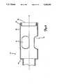
- FIG. 2is a perspective view in partial cross section of a distal portion of the device of FIG. 1;
- FIG. 3Ais a side view of the rotor housing of the device of FIG. 1;
- FIG. 3Bis a top view of the rotor housing of FIG. 3A;
- FIG. 4Ais a side view of a preferred embodiment of a rotor of the invention.
- FIG. 4Bis a side view of the rotor of FIG. FA rotationally displaced about its axis approximately 90° from the view of FIG. 4A;
- FIG. 5is a cross-sectional view of a preferred embodiment of a rotor housing of the invention.
- FIG. 6is a perspective view of the distal portion of an alternative embodiment of the invention.
- FIG. 7is a cross-sectional view of a preferred drive means for use with the present invention.
- FIG. 8Ais an end view of an alternative embodiment of a rotor housing of the invention.
- FIG. 8Bis an exploded side view of the housing of FIG. 8A, as assembled.
- FIG. 9is an exploded perspective view of a turbine for use in the drive means of FIG. 7;
- FIG. 10is a side view in partial cross section of a distal portion of an alternative embodiment of the invention.
- FIGS. 1-4One preferred embodiment of a medical device of the invention is shown in FIGS. 1-4.
- This devicegenerally includes an elongate, flexible shaft 10 carried within an elongate, generally tubular casing 20; a rotor 50 affixed to the shaft and carried within a rotor housing 70; and a drive means 100 operatively connected to the shaft for rotating the shaft.
- the shaft 10is elongate and generally cylindrical in shape and has a distal end 12 and a proximal end 14 (FIG. 7).
- the shaftis sized to be threaded, along with the rest of the device of the invention, along a vascular path within a patient's vascular system.
- the shaftwill commonly have an outer diameter of between about 0.25 and about 1.5 mm, with a range of about 0.35 to about 0.65 mm being preferred.
- the length of the shaftcan be varied fairly widely, depending upon the general types of locations within a vascular system intended to be accessed with the device. As a general rule, the shaft is desirably between about 50 cm and about 150 cm long, with a range of about 80 cm to about 100 cm providing a device which is useful for a wide variety of applications.
- the shaftis desirably highly flexible so that it may be threaded through a patient's vascular system with ease.
- the shaftmay be made of any of a wide variety of materials well known in the art, such as stainless steel.
- the shaftis formed of a shape memory alloy, such as a NiTi alloy.
- NiTi alloysuch as NiTi alloy.
- One important property of such alloysis that they exhibit superelasticity, i.e., they may be deflected to a much greater extent than most other metals, such as stainless steel before showing any permanent, plastic deformation. This property is explained in some detail in U.S. Pat. No.
- the shaftwould tend to take a permanent set, i.e., undergo plastic deformation, as it is guided along a tortuous vascular path. This would introduce a degree of curvature in the distal portion of the shaft 10. When the shaft is rotated, it will not rotate merely about its axis, but will also tend to spin somewhat wildly due to the curvature of the wire. If the shaft includes a rotor for degrading solid matter within the blood stream, this "whip" can readily lead to puncture of the vessel walls, as noted above.
- the shaft 10is formed of a "drawn-brazed strand" (DBS) cable.
- DBSdrawn-brazed strand
- Most cablescomprise a plurality of independent wire strands which are wrapped in a generally helical fashion about a central core wire. Although such a cable does tend to resist plastic deformation somewhat better than a single, unitary wire formed of the same material at the same diameter, the central wire strand of such a cable will tend to undergo plastic deformation to an extent proportional to that experienced by the larger diameter unitary wire.
- a DBS wire of the inventiona plurality of separate strands are wrapped in a helical fashion, but no central wire strand is employed.
- the individual wire strands (not shown) of a DBS wire of the inventionhave been twisted about o e another in a helical fashion, it is desirably drawn under pressure at high temperatures. As will be understood by those skilled in the art, this drawing and brazing of the wire can be used to meld the individual wire strands into a single wire having a larger diameter.
- Such a shaftgenerally appears the same as a solid wire, but the wire tends to retain some of the microstructure associated with the intertwined wire strands, yielding a wire with a tensile strength comparable to that of a cable.
- the individual wire strands used to form a DBS wiremay be formed of any suitable material. As with the unitary, single strand shaft described above, the DBS shaft may also be formed of a shape memory alloy such as a NiTi alloy, if so desired.
- the shaft 10is desirably carried within a shaft casing 20.
- the shaft casingis desirably generally tubular in shape such that the shaft 10 may be retained and rotated within the casing.
- the shaft casing 20desirably extends along and encloses substantially the entire length of the shaft between the drive means 100 and the housing 70.
- the shaft 10should be rotatable within the shaft casing so that, as the drive means 100 causes the shaft to rotate, the shaft casing 20 remains substantially stationary with respect to the drive means.
- the shaft casingshould be flexible and sized to permit it to be threaded along a vascular path as the device of the invention is positioned within a patient's vascular system.
- the shaft casingcomprises a tubular outer sleeve 22 formed of a biologically inactive polymeric compound, such as polyurethane or the like.
- FIG. 6depicts an alternative embodiment of the tubular outer sleeve 22 shown in FIGS. 1 and 2.
- the outer sleeveis generally the same as described above in connection with FIGS. 1 and 2, but the outer sleeve further includes an arcuate projection which extends generally radially outwardly toward one side of the sleeve 22, as shown.
- This projection 24includes a guide wire tracking channel 26 which may extend along substantially the entire length of the projection.
- This tracking channelpermits one to simply direct a guide wire to the desired location within a patient's vascular system and then direct the distal end of the present invention to that location by passing the guide wire through the channel 26 so that the device follows the path of the guide wire accurately.
- the projectiondesirably terminates at a position proximally of the rotor housing 70 so that it does not interfere with the flow of fluid during opera ion of the device.
- the shaft casing 20includes an elongate inner bearing 26 disposed between the outer sleeve 22 of the casing and the shaft 10 to reduce friction between the outer sleeve and the shaft.
- the bearingis desirably free-floating, i.e., it is not attached to any other element of the device, but rather is simply retained between the outer sleeve and the shaft.
- a helical coilas shown in the drawings.
- Such helical coilsare well known in the art and are most commonly used as structural elements of guide wires. They generally comprise an elongate wire strand, usually stainless steel wire, which is wrapped in a helical fashion about a mandrel and then removed from the mandrel.
- a standard "Y-type” connectormay be attached to the outer sleeve 22 toward its distal end.
- These types of connectorsare well known in the medical field and need not be discussed at great length here.
- theyinclude a body portion 32 and an inlet tube 34.
- the body portion 32is generally axially alligned with the outer sleeve 22 while the inlet tube 34 is angled distally outwardly from the body portion 32.
- the inlet tube 34is in fluid communication with the interior of the shaft casing 20, permitting one to introduce any of a wide variety of fluids into the casing.
- the Y type connectoris replaced by an infusion line 34', which may be formed of a length of flexible tubing or the like.
- the infusion linemay be affixed to the sleeve 36 of the housing of the drive means 100 by means o of a Luer fitting 35' or the like.
- the infusion line 34'is in fluid communication with the interior of the shaft casing 20.
- Fluids which may commonly be used in connection with the present deviceinclude saline solution, contrast medium (for enhancing the radiographic visibility of the device) and fibrinolytic solutions (for medically breaking down fibrin, a major component of most thrombi).
- saline solutionfor enhancing the radiographic visibility of the device
- fibrinolytic solutionsfor medically breaking down fibrin, a major component of most thrombi.
- a rotor 50which may also be referred to as an "impeller," is affixed to the shaft 10 adjacent the distal end thereof for rotation therewith.
- the rotor 50generally includes a central body 52 having at least one blade 56 carried thereon.
- the central body 52is desirably generally tubular in shape, having a cylindrical aperture 54 extending through the body along the axis thereof. As explained in more detail below, this aperture 54 is intended for receiving a portion of the shaft 10 adjacent its distal end 12. Any number of blades 56 may be carried about the central body 52.
- the rotor 50includes a pair of generally diametrically opposed blades 5 which extend generally radially outwardly of the central body 52.
- each of the bladesis semi-elliptical in shape and is positioned diametrically opposite the other blade.
- Each bladeis desirably positioned within a plane which obliquely intersects the axis A of the shaft, and the opposite blade is substantially a mirror imaqe of the first blade.
- This constructionis not unlike that of the propeller of a prop style airplane, the oblique orientation of the blades 56 causing fluid to be thrust generally axially rearwardly of the rotor when the rotor is caused to rotate.
- FIGS. 4A and BA particularly preferred embodiment of a rotor of the invention is shown in FIGS. 4A and B.
- the bladesextend generally radially outwardly of the body 52 from diametrically opposite locations.
- each bladespirals in a generally helical fashion along the length of the body.
- each bladeextends about approximately 180° of the circumference of the body 52 between the blade's proximal 58 and distal 60 ends.
- the rate at which the blade 56 follows around the circumference of the body along its lengthcan be varied as desired.
- a plane within which a segment of the blade liesis oriented at an angle theta of approximately 40° from a plane orthogonal to the axis A of the body 52.
- fibrinis generally formed of elongate strands of a proteinaceous material.
- fibrinwill tend to become wrapped around the body 52 of the rotor if the rotor is not accelerated from an initial stationary position to full rotational speed quickly enough.
- the drive means 100 of the inventionis intended to permit sufficient torque to be applied to the shaft 10 to reach maximum rotational speed rather quickly to avoid this problem.
- a sharpened leading edge 62may be provided adjacent the distal end 60 of each blade 56.
- the leading edge of the bladesdo not lie in a plane orthogonal to the axis A of the body 52 as do the trailing edges 64 at the proximal end 58 of the blades. Instead, the leading edge lies within a plane which is angularly displaced from an orthogonal plane through an angle alpha.
- This angle alphais desirably between about 30 and about 60°, with a range of between about 40 and about 45° being preferred. This provides a sharp, acute angle at the distal end of the blade, permitting the sharpened distal edge of the blade to slice the fibrin before it can become twisted about the rotor.
- the rotormay be affixed to the shaft by any suitable means.
- a distal portion of the shaft 10is received within the aperture 54 formed in the body 52 of the rotor.
- the shaftmay then be permanently adhered to the rotor in any desirable fashion, such as by brazing or by means of a curable, biologically inert cementitious material.
- a thrombectomy device of the inventionalso includes a rotor housing 70 carried about the rotor and within which the rotor rotates.
- the housingcomprises a generally cylindrical wall 72 having an inner diameter greater than the outer diameter of the rotor 50 so that the rotor may freely rotate within this housing.
- the inner diameter of the housing 70is only slightly greater than the outer diameter of the rotor 50. This close proximity between the rotor and the wall 72 of the housing increases the shear force applied to a fluid passing through the housing as the rotor is rotated. This heightened shear force will serve to further break up the thrombus carried within the blood, permitting the rotor to more rapidly degrade a thrombus entrained in the fluid into sufficiently small particles.
- the axis A H of the housing 70is desirably substantially aligned with the axes of the rotor 50 and shaft 10.
- the rotor housing 70includes a plurality of ports 74 which pass through the cylindrical wall 72.
- the portsare desirably spaced equiangularly about the circumference of the housing.
- the rotor 50is desirably positioned generally toward the distal end 78 of the housing, as shown in FIG. 2.
- the ports 74are positioned about the wall 72 of the housing immediately distally behind the rotor 50.
- the low pressure adjacent the distal end of the rotortends to draw the blood being expelled through the ports back through the rotor, thereby creating a recirculating vortex wherein a substantial portion of the fluid exiting through the ports tends to pass through the rotor repeatedly.
- the rotorWhen a thrombus is drawn into the housing by the rotor, the rotor will tend to divide it into a number of smaller particles, which may well remain too large. However, these particles will be entrained in the blood expelled through the ports and will therefore tend to be drawn back into the rotor and become degraded even further. After a sufficient number of passes through this recirculating vortex, the thrombus may be broken into a large number of very small, discrete particles. These particles may be made small enough to substantially eliminate the risk that they would tend to cause blood to coagulate about them again to produce additional thrombi or cause any distal embolization.
- the rotorWhen in use, the rotor will usually be positioned within the confines of a vascular channel adjacent the location, or suspected location, of a thrombus. When the rotor is rotated and causes blood to be ejected through the ports 74, the ejected fluid will impinge upon the vascular wall, tending to urge the housing away from the vascular wall as a reaction to this impinqinq fluid. If each of the three or more equiangularly spaced ports are of substantially the same size, the fluid volume passing through each port and the rate at which the fluid is expelled from the ports will be substantially equivalent.
- the reactionary force acting against the housing to urge the housing away from the vascular wallwill become equalized when each of the plurality of equiangularly spaced, similarly sized ports are approximately the same distance away from the vascular wall.
- the fluid flowing through the ports in the housingwill tend to automatically center the housing and the rotor within the vascular channel when the rotor rotates.
- the housingwill not only automatically be centered when in use, but it will tend to remain centered within the vascular channel. If only two ports are utilized (as in the device shown in FIG. 1), though, the housing may not remain centered. The fluid expelled through the two diametrically opposed ports will tend to ensure that the housing remains equally spaced from portions of the vascular wall along a line passing through both of the ports, i.e., in a horizontal plane in FIG. 1.
- the housingmay be provided with a generally inwardly extending distal bead 76 adjacent its distal end.
- This distal beadis desirably rounded to provide the housing with a rounded distal end 78 for contacting tissue as the device is deployed within a vascular system.
- the distal beadmay be formed on the housing by inwardly deforming a distal portion of the cylindrical wall to form an annular bead disposed within a distal segment of the housing. Two possible bead constructions are best seen in FIG. 5, which depicts one useful shape, and FIGS. 8 and 9, which show an alternative embodiment of such a bead.
- Such a rounded distal end 78tends to be less traumatic than either the mor blunt distal end 78 shown in FIG. 2 or an exposed rotor 50 which is not surrounded by a housing, as is most common in the prior art.
- this distal bead 76is desirably generally inwardly extending, though it may also extend outwardly of the cylindrical wall 72 of the housing.
- the inner diameter of the housing adjacent its distal end, i.e., adjacent the distal bead 76,is desirably less than the maximum outer diameter of the rotor 50. This serves as a further safety measure in that if the shaft 10 breaks, the rotor will be unable to pass through the distal end of the housing. This prevents the rotor and a broken off distal portion of the shaft from becoming left within the blood stream of the patient if the shaft does indeed fail.
- FIG. 8depicts an alternative construction of the housing 70 of the invention.
- the housingis desirably integrally formed of a single, unitary piece of material, such as surgical stainless steel.
- the housing 70is formed of two separate elements which can be affixed to one another when assembling the invention.
- the cylindrical wall 72which is carried about the rotor forms a first, distal element which can be permanently attached to the other, proximal segment 90 by any suitable means, such as by brazing.
- the proximal segment 90has a central apertur 92 extending centrally therethrough for rotatably receiving the shaft 10 to position a proximal portion of the shaft and the rotor attached thereto in the center of the cylindrical distal segment 72.
- a plurality of fins 79are positioned equiangularly about a generally frustoconical housing insert 94.
- the insert 94 and the finsare sized to be closely received within the confines of the cylindrical wall 72 when the housing is assembled.
- the insertdesirably tapers radially outwardly in a proximal direction from an initial outer diameter only slightly greater than that of the shaft 10 to an outer diameter adjacent its proximal end generally equal to the inner diameter of the cylindrical wall 72. Although this taper may be generally linear, in the preferred embodiment shown the rate of taper is much greater adjacent its proximal end.
- An annular abutment 96may be provided adjacent the proximal end of the housing insert 94.
- This abutmenthas an outer diameter greater than the inner diameter of the cylindrical wall 72 and thus serves to abut the proximal end of the wall when the housing is assembled. If so desired, the wall 72 may be affixed directly to this abutment.
- the outer diameter of the abutment 96is substantially equal to that of the cylindrical wall to provide the housing with a smooth outer surface.
- the housing insert 94may include a plurality of fins 79 positioned equiangularly about its circumference.
- the number of fins employedis desirably equal to the number of ports 74 in the housing, and one fin may be positioned immediately adjacent each port. If so desired, the fins may be parallel to the major axis of their respective, generally elliptical ports.
- any solid matter, such as a thrombus, entrained within the fluidwill strike the fins, which form a part of the housing and are thus stationary with respect to the spinning rotor. Solid matter will tend to be broken up when it impacts the fins, so the fins serve to speed up the degradation of thrombi or the like within the fluid.
- a connector 80may extend proximally of the cylindrical wall 72 of the rotor housing 70 and permit the housing to be attached to the distal end of the shaft casing 20.
- the connector 80includes a first segment 82 adjacent and connected to the cylindrical wall 72 of the housing.
- the outer diameter of this first segment 82is desirably substantially equal to the inner diameter of the outer sleeve 22 of the shaft casing adjacent its distal end so the first segment 82 may be closely received within and retained by a distal portion of the outer sleeve 22.
- the outer diameter of the cylindrical wall 72 of the housingis desirably substantially equal to the outer diameter of the shaft casing 20 to present a relatively smooth outer surface at the junction between the housing and the shaft casing.
- the decrease in diameter between the cylindrical wall 72 and the first segment 82may be relatively abrupt, defining a generally rearwardly facing annular shoulder 84 for abutting the distal end of the outer sleeve 22.
- the first segment 82may be cemented to the lumen of the outer sleeve by means of an epoxy or the like (not shown).
- the connector 80may also include a second segment 86 which is disposed proximally of the first segment 82 and is attached thereto.
- the maximum dimension of this second segmentis desirably larger than the inner diameter of the inner bearing 26. The second segment thus serves to distally limit the axial movement of the inner bearing and serves to retain the bearing in place about the shaft 10 within the outer sleeve 22.
- the second segment 86is generally rectangular in cross section, as indicated in FIGS. 3A and B, rather than being generally cylindrical.
- the second segmentmay be substantially solid in cross section, but includes a central aperture passing therethrough for receiving the shaft 10.
- the axis of this cylindrical apertureis preferably substantially aligned with the axis of the shaft and the aperture is sized to permit the shaft to freely rotate therein.
- the second segmentthus serves to support the shaft in a spaced relationship with respect to the shaft casing 20 and helps to ensure that the rotor is axially centered within the cylindrical wall of the housing rather than abutting against the wall.
- Utilizing a generally rectangularly shaped second segment having maximum dimensions less than the diameter of the first segment 82provides a space between the second segment and the shaft casing 20. This space allows fluids, such as the contrast mediums or fibrinolyitic solutions noted above, to pass distally from within the casing through the housing and into the vascular channel.
- FIG. 10depicts an alternative embodiment of a rotor housing 70 and connector 80 of the invention.
- the connectordoes not include a second segment 86 disposed rearwardly of the first section 82.
- a coiled support member 86'is utilized.
- the support member 86'is carried within the first segment 82 and extends along the length thereof from a position adjacent the annular shoulder 84 to the proximal end of the first segment.
- the support memberdesirably comprises a widely spaced helical coil formed of a wire having a diameter adapted to extend radially inwardly of the first segment a sufficient distance to provide lateral support to the shaft 10 carried within the helical coil.
- the axes of the shaft, the first segment and the helical support member 86'are desirably substantially aligned with one another.
- Adjacent turns of the helically coiled wireare desirably spaced apart from one another. This permits fluid to pass through the support member 86' at relatively high flow rates as the space between the adjacent turns effectively defines a generally helical path along which fluid may freely flow between the interior of the shaft casing 20 and the rotor housing 70.
- the direction of this fluid flowis schematically represented by arrows in FIG. 10 and, as indicated by the bi-directional character of these arrows, fluid may flow in either direction along this helical channel--if one is aspirating fluid from within the vascular channel, the fluid would flow generally proximally, while fluid would flow generally distally if one were delivering a fibrinolytic solution or the like into the vessel through the shaft casing.
- the connector 80 of the housingis desirably also provided with a shaft support sleeve 88 for supportingly receiving a portion of the shaft adjacent its distal end.
- the support sleeve 88may be of any desired construction, but preferably comprises a thin walled stainless steel tube, known in the art as a "hypotube,” having a length of between about 0.25 and about 0.35 inches in length.
- the sleeveis sized to permit the shaft to rotate freely therein, yet limit lateral movement of the shaft so that it may stabilize the shaft in a position wherein the axis of its distal portion is substantially aligned with the axis A H of the housing.
- the support sleeve 88may extend distally through the first 82 and second 86 segments of the housing (or the first segment 82 and the support member 86' in the embodiment of FIG. 10) to a position within the rotor housing 70 immediately adjacent the rotor 50 (as best seen in FIGS. 2 and 10).
- the present inventionalso includes a drive means 100 for rotating the shaft 10 within the shaft casing 20 to cause the rotor 50 to rotate.
- a drive means 100for rotating the shaft 10 within the shaft casing 20 to cause the rotor 50 to rotate.
- Any suitable drive meansmay be used, but it is preferred that the drive means be capable of rapidly rotating the shaft and the rotor.
- a rotor of the inventionis desirably rotated at speeds between about 80,000 and about 150,000 rpm, with an operating range of between about 100,000-135,000 rpm being preferred.
- this drive meansmay be of any type which will rotate the shaft 10 and rotor 50 at the desired speed, such as a high-speed electric motor, in a preferred embodiment an air-driven turbine is employed.
- this drive meansincludes a housing 102 having first and second sections (104 and 106, respectively).
- the first and second sections 104, 106are adapted to be sealinqly affixed to one another to define a short, substantially air tight cylinder.
- the first section 104desirably comprises a substantially flat, circular disc.
- the second section 106comprises a generally flat, circular distal face 110 and a peripheral wall 108 extends generally perpendicularly laterally from this face 110.
- the diameter of the first section 104 of the housingis greater than the inner diameter of the peripheral wall 108 and may be substantially equal to the outer diameter of that wall.
- the housingmay be formed of any suitable material, in the preferred embodiment it is formed of a polymeric material, such as a high density, machinable plastic, which may be sonically welded to permit the first and second sections 104, 106 to be sealingly affixed to one another with ease.
- an air inlet 120 and an air outlet 134may be provided in and extend radially outwardly through the peripheral wall 108.
- the air inletincludes an inlet tube 124 which extends through the inlet port 122 in the housing and is adapted for attachment to an air supply.
- a pressurized air supplyis provided, with pressures usually in the range of about 35 to about 50 psi.
- the inlet tubeis preferably configured to be sealingly received within and retained at one end of a length of flexible hosing (not shown), the other end of which may be operatively attached to the pressurized air supply to direct pressurized air to the drive means 100 through the inlet tube 124.
- the drive means 100desirably also includes an air outlet 134.
- This air outletallows air to escape the housing 102 so that a continuous flow of air may flow into the housing through the air inlet 120.
- the air outlet 134may be positioned substantially anywhere on the housing. In the embodiment shown in FIG. 1, though, the air outlet comprises a port which extends radially outwardly through the peripheral wall 108. In a particularly preferred embodiment, the air outlet 134 is positioned about the circumference of the peripheral wall relatively close to the air inlet in a direction opposite the direction of flow of air within the housing (generally clockwise in FIG. 1).
- the air outletis provided with an outlet tube 138 carried externally of the housing to direct the flow of air exiting the housing.
- FIG. 7An alternative embodiment of a drive means 100 which has been found to work particularly well with the present invention is shown in FIG. 7.
- the construction of this drive meansis similar to that described above for the embodiment of FIG. 1.
- the housing 102has a generally flat, circular first section 104 which is sealinqly affixed to the second section 106 to define a short, substantially air-tight cylindrical housing.
- this housingis desirably formed of a machinable polymeric material which may be sonically welded to sealinqly affix the first and second sections 104, 106 to one another.
- the positions of the air inlet 120 and air outlet 134 in this embodimentdiffer from those in the embodiment shown in FIG. 1, though.
- both the air inlet and the air outletpass through the first section 104 of the housing, i.e., at the housing's proximal end.
- the air inlet 120includes an inlet port 122 which passes through the first section 104 of the housing and within which is retained an inlet tube 124.
- An air supply connector 126may be provided for sealinqly receiving an air supply, such as a length of flexible housing 123, in fluid communication with the inlet tube 124.
- the inlet tube 124includes a terminal segment 130 which is positioned immediately adjacent the turbine 150, as explained in more detail below.
- a venturi segment 128is provided in the inlet tube between the proximal end of the inlet tube and the terminal segment 130.
- the venturi segmenthas a larger diameter at its proximal end than at its distal end where it is sealinqly affixed to the terminal segment.
- this relatively rapid drop in cross sectional area along the venturi segmentwill tend to accelerate the flow of fluid, i.e., air, as it passes from the air supply to the terminal segment 130 of the inlet tube.
- the axis of the inlet tube 124is desirably substantially aligned with the axis of the generally cylindrical housing 102 so that the terminal segment 130 of the inlet tube may be positioned centrally within the housing immediately adjacent the axis of the turbine 150, as explained below.
- the air outlet 134 of the present embodimentdesirably passes through the first section 104 of the housing 102. In this manner, air may be vented rearwardly out of the housing.
- the air outlet 134includes an outlet port 136 which extends through the first section 104 of the housing.
- a plurality of such outlet portsare utilized, the outlet ports being spaced equiangularly about the axis of the cylindrical housing with the axes (not shown) of the outlet ports 136 being generally parallel to and spaced radially outwardly from the axis of the housing.
- a baffle means 140may be provided in each outlet port 136 to diffuse the flow of air out of the housing.
- the baffle means 140comprises a generally porous, sponge-like material which dampens the flow of air, yet permits air to pass therethrough.
- the drive means 100also includes a turbine 150 which may be caused to rotate by the flow of air through the inlet tube 124 of the air inlet.
- a turbine 150which may be caused to rotate by the flow of air through the inlet tube 124 of the air inlet.
- Any of a wide variety of suitable turbinesmay be utilized, but a preferred embodiment of a turbine for use with the present invention is shown in FIGS. 7 and 9.
- This turbine 150may be formed as two separate elements, i.e., a distal segment 152 and a proximal segment 154, which are joined together to produce the turbine after being independently formed.
- the distal segment 152 of the turbineis generally disk-shaped and includes a plurality of generally triangular, wedge-shaped upright projections 156 spaced about its periphery.
- Opposing walls of adjacent projectionsare desirably spaced apart from and generally parallel to one another to define an uprightly open channel 158 therebetween.
- the wedges and resulting channelsare desirably spaced equiangularly about the periphery of the distal segment 152.
- the upright projections 156desirably do not extend all the way to the center of the disk-shaped distal segment, but rather extend inwardly from the periphery a specified distance, which may be on the order of one-half the radius of the distal segment 152.
- the channels 158are desirably oriented generally tangentially with respect to the periphery of this central portion 160 so that as air strikes the center of the turbine, as explained in more detail below, it will be urged tangentially outwardly through the channels 158 and cause the turbine to spin.
- the central portion 160 of the distal segment of the turbineis generally conical in shape and comes to a peak 162 generally along the axis of the disk-shaped distal segment.
- the central portion 160has a generally elliptical profile (as best seen in the cross sectional view of FIG. 7) rather than having a substantially flat incline.
- the proximal portion 154 of the turbineis also generally disk-shaped and desirably has an outer diameter substantially equal to that of the distal segment 152.
- the proximal segmentgenerally includes a central portion 170 and a peripheral portion 169 extending radially outwardly of the central portion.
- the peripheral portion 169includes a plurality of fingers 168 which extend generally tangentially outwardly of the central portion 170. These fingers are adapted to be matingly received within, and fill a portion of, the channels 158 in the distal segment 152.
- the fingers 168are generally rectangular in cross section and extend generally downwardly in FIG.
- the fingersmay be varied as desired, they desirably extend downwardly within the channels 158 to a depth of approximately one half the depth of the channel.
- the distal and proximal segments 152, 154are desirably formed of an injection moldable polymeric material which may be sonically welded. This permits the individual segments to be accurately and inexpensively produced by injection molding and permits the segments to be permanently affixed to one another by the process of sonic welding. If so desired, a plurality of sacrificial nibs 166 may be spaced about the proximal and/or distal segments. During the sonic welding process, these sacrificial nibs will be broken down and will serve as a weldment for securely attaching the proximal and distal segments to one another.
- the central portion 170 of the proximal segment 154desirably includes a centrally located, generally frustoconical cap 174.
- the capWhen the turbine 150 is assembled, the cap will be spaced away from the central portion 160 of the distal segment to define an air flow chamber (175 in FIG. 7) therebetween.
- the capincludes a central port 176 through which a stream of air may pass and an upstanding lip 177 may be provided about this port. The thickness of the lip 177 may decrease proximally, as shown in FIG. 7.
- the axis of the turbine 150substantially coincides with that of the housing 102 of the drive means and inlet tube 124 of the air inlet.
- the turbineis positioned immediately distally of the inlet tube.
- the upstanding lip 177 of the proximal segment 154 of the turbineis desirably positioned immediately adjacent the distal end of the terminal segment 130 of the inlet tube; if so desired, a short length of the lip 177 may even be rotatably positioned within the distal end of the terminal segment. This ensures that air flowing into the drive means through the inlet tube 124 will flow directly into the chamber 175 of the turbine.
- venturi segment 128 of the inlet tubeserves to accelerate the flow of air through the tube.
- the airthus enters the chamber 175 at a rather high flow rate, which serves to relatively rapidly accelerate the turbine to its full rotational velocity.
- the moment of inertia of the turbinewill be reduced and the turbine may be accelerated even more rapidly.
- the shaft 10 of the deviceis connected to the turbine 150 for rotation therewith by means of a drive coupling 180.
- the drive couplingmay be attached to the turbine and the shaft by any suitable means.
- the turbineincludes a generally cylindrical drive coupling recess for receiving the tubular drive coupling 180 and the drive coupling may be fixed within this recess.
- the drive coupling 180desirably also includes a central recess (not separately shown) within which the shaft 10 may be received and within which the shaft may be affixed.
- the drive means 100desirably includes a distally extending, manually graspable sleeve 36, which may be formed integrally with the second section 106 of the housing. If so desired, the outer surface of this sleeve may be provided with a rougher texture (as shown in FIG. 1) to permit the sleeve to be more readily and more securely grasped by an operator of the device.
- the sleeve 36is desirably tubular in shape and is adapted to receive the drive coupling 180 and a proximal portion of the shaft 10 therewithin. In order to ensure that the axes of the drive coupling 180 and turbine 150 substantially coincide with that of the sleeve 36, bearings 184 may be utilized.
- two sets of bearingsare used, with one being carried adjacent the distal end of the drive coupling and the other being spaced proximally at a location adjacent the drive coupling recess 182 of the turbine.
- Any suitable bearingmay be used, but the bearing should permit the drive coupling 180 to freely rotate with respect to the sleeve 36 as the turbine and shaft are rotated.
- the sleeve 36is elogate in shape and serves to encase structural elements of the device in addition to the drive coupling 180 and bearings 184.
- a spacer 188is carried within the sleeve at a position immediately distally adjacent the drive coupling 180.
- the spaceris generally tubular in shape and is adapted to be closely received within the sleeve 36.
- the spacerincludes a central bore 190 extending through its length, the bore being sized to rotatably receive both the shaft 10 and the inner bearing 26 previously described and support these elements generally centrally along the axis of the sleeve.
- the bearing 26is not affixed to any other element of the device, including the spacer 188, but rather is "free floating.”
- the spacer 188may be affixed within the lumen of the sleeve 36.
- an O-ring 192 or the likemay be positioned between the spacer and the inner wall of the sleeve. This prevents the fluid used to drive the turbine, i.e., air, from entering the shaft casing 20 and flowing into the bloodstream. Also, it prevents fluids within the casing, such as blood or fluids which are delivered to the casing 20 through infusion line 30', from entering the housing 102 of the drive means.
- a portion of the spacer immediately adjacent the attachment of the infusion line 30' to the sleeve 36is desirably spaced away from the inner wall of the sleeve in order to permit fluid to pass from the infusion line into the casing as previously explained.
- the outer sleeve 22 of the shaft casingmay be affixed directly to the sleeve 36, in a preferred embodiment the outer sleeve is affixed to a swivel connector 194 retained by the sleeve.
- the swivel connectorincludes a body 196 which is retained within the lumen of the sleeve and a distal extension 195 which protrudes distally out of the sleeve through the sleeve's distal exit 38.
- an O-ring 196may be disposed between the body 196 of the swivel connector and the sleeve 36.
- the swivel connectoris desirably rotatable within the lumen of the sleeve, and a bushing 198 or the like may be utilized to ensure that the swivel connector can rotate freely with respect to the sleeve.
- the tubular distal extension 195may extend forwardly of the sleeve, as noted above, and desirably is adapted to closely receive the outer sleeve 22 of the shaft casing therein. If so desired, the outer sleeve may extend along substantially the entire length of the swivel connector.
- the outer sleeve 22may be sealinqly affixed to the swivel connector by any suitable means which will afford a generally fluid tight seal between the swivel connector and the shaft casing 20.
- a readily available pressurized air supplymay be utilized to rotate the shaft 10 and rotor 50 of the device.
- the design of the preferred embodimentis configured to maximize the acceleration of the shaft. It was also noted above that if the shaft is accelerated too slowly, there is a risk that fibrin contained within a thrombus may become wrapped about the rotor rather than being broken into a number of pieces thereby.
- a turbinewhich will rapidly accelerate the shaft from an initial stationary state to its full rotational speed, this risk is minimized and substantially all of the fibrin contained within a thrombus may be degraded into very small, discrete pieces.
- Airwas supplied to the drive means 100 to turn the rotor at between about 100,000 and about 135,000 rpm.
- the homogenized materialwas then filtered through a series of nylon screens having varying pore sizes.
- the first screenhad a 200 micron pore size, the second was 100 microns, the third was 47 microns, and the final screen had 13 micron pores.
- clotscould be substantially completely degraded into rather fine particles.
- the larger clotswould generally require longer periods of time, such as 45 seconds, in order to be completely degraded, while smaller clots may be degraded in 15 seconds or less.
- the inventionmay readily degrade thrombi in less than a minute to a point wherein 99.76% by weight of the thrombus will pass through a 13 micron screen.
Landscapes
- Health & Medical Sciences (AREA)
- Surgery (AREA)
- Life Sciences & Earth Sciences (AREA)
- Medical Informatics (AREA)
- Animal Behavior & Ethology (AREA)
- Engineering & Computer Science (AREA)
- Biomedical Technology (AREA)
- Heart & Thoracic Surgery (AREA)
- Vascular Medicine (AREA)
- Molecular Biology (AREA)
- Nuclear Medicine, Radiotherapy & Molecular Imaging (AREA)
- General Health & Medical Sciences (AREA)
- Public Health (AREA)
- Veterinary Medicine (AREA)
- Surgical Instruments (AREA)
- Orthopedics, Nursing, And Contraception (AREA)
- Materials For Medical Uses (AREA)
Abstract
Description
Claims (23)
Priority Applications (7)
| Application Number | Priority Date | Filing Date | Title |
|---|---|---|---|
| US07/713,384US5284486A (en) | 1991-06-11 | 1991-06-11 | Self-centering mechanical medical device |
| PCT/US1992/004787WO1992022253A1 (en) | 1991-06-11 | 1992-06-08 | Self-centering mechanical medical device |
| EP92914410AEP0592528B1 (en) | 1991-06-11 | 1992-06-08 | Self-centering mechanical medical device |
| AT92914410TATE156687T1 (en) | 1991-06-11 | 1992-06-08 | SELF-CENTERING MECHANICAL MEDICAL DEVICE |
| DE69221621TDE69221621T2 (en) | 1991-06-11 | 1992-06-08 | SELF-CENTERING MECHANICAL, MEDICAL DEVICE |
| JP5500956AJPH07500977A (en) | 1991-06-11 | 1992-06-08 | Self Centering Machine Medical Instrument |
| US08/193,490US5569275A (en) | 1991-06-11 | 1994-02-08 | Mechanical thrombus maceration device |
Applications Claiming Priority (1)
| Application Number | Priority Date | Filing Date | Title |
|---|---|---|---|
| US07/713,384US5284486A (en) | 1991-06-11 | 1991-06-11 | Self-centering mechanical medical device |
Publications (1)
| Publication Number | Publication Date |
|---|---|
| US5284486Atrue US5284486A (en) | 1994-02-08 |
Family
ID=24865928
Family Applications (1)
| Application Number | Title | Priority Date | Filing Date |
|---|---|---|---|
| US07/713,384Expired - LifetimeUS5284486A (en) | 1991-06-11 | 1991-06-11 | Self-centering mechanical medical device |
Country Status (6)
| Country | Link |
|---|---|
| US (1) | US5284486A (en) |
| EP (1) | EP0592528B1 (en) |
| JP (1) | JPH07500977A (en) |
| AT (1) | ATE156687T1 (en) |
| DE (1) | DE69221621T2 (en) |
| WO (1) | WO1992022253A1 (en) |
Cited By (105)
| Publication number | Priority date | Publication date | Assignee | Title |
|---|---|---|---|---|
| US5498238A (en)* | 1990-06-15 | 1996-03-12 | Cortrak Medical, Inc. | Simultaneous angioplasty and phoretic drug delivery |
| US5569275A (en)* | 1991-06-11 | 1996-10-29 | Microvena Corporation | Mechanical thrombus maceration device |
| WO1997009010A1 (en)* | 1995-09-07 | 1997-03-13 | Innerdyne, Inc. | Method and system for direct heating of fluid solution in a hollow body organ |
| US5665062A (en)* | 1995-01-23 | 1997-09-09 | Houser; Russell A. | Atherectomy catheter and RF cutting method |
| US5730717A (en)* | 1994-12-16 | 1998-03-24 | Gelbfish; Gary A. | Method and associated device for removing material from body |
| USD401334S (en) | 1996-11-25 | 1998-11-17 | Microvena Corporation | Medical device handle |
| WO1998057603A1 (en)* | 1997-06-17 | 1998-12-23 | Innerdyne, Inc. | System for direct heating of fluid solution in a hollow body organ and methods |
| WO1999032039A1 (en) | 1997-12-19 | 1999-07-01 | Neurovasx, Inc. | Thrombus macerator catheter |
| US5928218A (en)* | 1994-12-16 | 1999-07-27 | Gelbfish; Gary A. | Medical material removal method and associated instrumentation |
| US5938672A (en)* | 1996-07-26 | 1999-08-17 | Kensey Nash Corporation | System and method of use for revascularizing stenotic bypass grafts and other blood vessels |
| US6090118A (en) | 1998-07-23 | 2000-07-18 | Mcguckin, Jr.; James F. | Rotational thrombectomy apparatus and method with standing wave |
| US6254571B1 (en) | 1996-04-18 | 2001-07-03 | Applied Medical Resources Corporation | Remote clot management |
| WO2001054754A1 (en) | 2000-01-25 | 2001-08-02 | Bacchus Vascular, Inc. | Systems and methods for clot dissolution |
| US6287271B1 (en) | 1995-06-07 | 2001-09-11 | Bacchus Vascular, Inc. | Motion catheter |
| US20020173812A1 (en)* | 1997-07-24 | 2002-11-21 | Mcguckin James F. | Rotational thrombectomy device |
| US20020183787A1 (en)* | 2001-06-01 | 2002-12-05 | Velocimed, L.L.C. | Closure devices, related delivery methods and tools, and related methods of use |
| US20020188307A1 (en)* | 1998-04-10 | 2002-12-12 | Rafael Pintor | Neuro thrombectomy catheter |
| US20030020662A1 (en)* | 2001-04-27 | 2003-01-30 | Brian St. Hillaire | Diversity slot antenna |
| US20030028206A1 (en)* | 1999-02-02 | 2003-02-06 | Samuel Shiber | Vessel cleaner and barrier |
| US20030037570A1 (en)* | 2000-04-28 | 2003-02-27 | Sklyarevich Vladislav E. | Method for the rapid thermal treatment of glass and glass-like materials using microwave radiation |
| US20030093098A1 (en)* | 1998-04-10 | 2003-05-15 | Heitzmann Harold A. | Rotational atherectomy system with stationary cutting elements |
| US20030187468A1 (en)* | 1999-02-02 | 2003-10-02 | Samuel Shiber | Vessel cleaning system with asymmetrical auto retracting agitator |
| US20030208232A1 (en)* | 2002-05-06 | 2003-11-06 | Velocimed, L.L.C. | PFO closure devices and related methods of use |
| US20030211066A1 (en)* | 1995-06-22 | 2003-11-13 | 3M Innovative Properties Company | Stable hydroalcoholic compositions |
| US20030215418A1 (en)* | 1997-01-09 | 2003-11-20 | 3M Innovative Properties Company | Hydroalcoholic compositions thickened using polymers |
| US20040097995A1 (en)* | 1996-07-26 | 2004-05-20 | Nash John E. | System and method of use for agent delivery and revascularizing of grafts and vessels |
| US6758851B2 (en) | 1999-02-02 | 2004-07-06 | Samuel Shiber | Vessel cleaner |
| US20040220604A1 (en)* | 2003-04-30 | 2004-11-04 | Fogarty Thomas J. | Tissue separation apparatus and method |
| US20040267306A1 (en)* | 2003-04-11 | 2004-12-30 | Velocimed, L.L.C. | Closure devices, related delivery methods, and related methods of use |
| US20050171592A1 (en)* | 2002-06-24 | 2005-08-04 | Majercak David C. | Spiral centering catheter |
| US6929633B2 (en) | 2000-01-25 | 2005-08-16 | Bacchus Vascular, Inc. | Apparatus and methods for clot dissolution |
| US6936056B2 (en) | 1996-07-26 | 2005-08-30 | Kensey Nash Corporation | Intravascular system for occluded blood vessels and guidewire for use therein |
| US20050240146A1 (en)* | 2004-04-27 | 2005-10-27 | Nash John E | Thrombectomy and soft debris removal device |
| US20060009800A1 (en)* | 2003-04-11 | 2006-01-12 | Velocimed Pfo, Inc. | Closure devices, related delivery methods, and related methods of use |
| US20060121071A1 (en)* | 1995-06-22 | 2006-06-08 | 3M Innovative Properties Company | Stable hydroalcoholic compositions |
| US20060173244A1 (en)* | 2004-09-30 | 2006-08-03 | Boston Scientific Scimed, Inc. | System and method of obstruction removal |
| US20060263396A1 (en)* | 1995-06-22 | 2006-11-23 | 3M Innovative Properties Company | Stable hydroalcoholic compositions |
| US20060264989A1 (en)* | 1999-10-22 | 2006-11-23 | Rex Medical, L.P. | Double balloon thrombectomy catheter |
| US20060281663A1 (en)* | 2005-06-13 | 2006-12-14 | 3M Innovative Properties Company | Foamable alcohol compositions, systems and methods of use |
| US20070027055A1 (en)* | 2003-09-29 | 2007-02-01 | Koivisto Bruce M | High alcohol content gel-like and foaming compositions |
| US20070032808A1 (en)* | 2005-08-03 | 2007-02-08 | Azam Anwar | System and method for addressing total occlusion in a vascular environment |
| US20070038225A1 (en)* | 2005-08-12 | 2007-02-15 | Cook Incorporated | Thrombus removal device |
| US20070065383A1 (en)* | 2005-03-07 | 2007-03-22 | Fernandez De Castro Maria T | High alcohol content foaming compositions with silicone-based surfactants |
| US20080065124A1 (en)* | 1999-08-19 | 2008-03-13 | Foxhollow Technologies, Inc. | High capacity debulking catheter with razor edge cutting window |
| US20080097499A1 (en)* | 2004-04-27 | 2008-04-24 | Nash John E | Thrombectomy and soft debris removal device |
| US20080103446A1 (en)* | 2006-10-04 | 2008-05-01 | Pathway Medical Technologies, Inc. | Interventional catheters incorporating aspiration and/or infusion systems |
| US7367982B2 (en) | 1996-07-26 | 2008-05-06 | Kensey Nash Corporation | Method for opening a lumen in an occluded blood vessel |
| US20080125798A1 (en)* | 2006-11-08 | 2008-05-29 | Cook Incorporated | Thrombus removal device |
| US7479147B2 (en) | 1998-04-10 | 2009-01-20 | Ev3 Endovascular, Inc. | Rotational atherectomy device |
| US20090187083A1 (en)* | 2008-01-18 | 2009-07-23 | Plaquetec Ltd. | Catheter |
| US7575586B2 (en) | 1998-01-30 | 2009-08-18 | St. Jude Medical Atg, Inc. | Medical graft connector or plug structures, and methods of making and installing same |
| US20090216180A1 (en)* | 2008-02-25 | 2009-08-27 | Fox Hollow Technologies, Inc. | Methods and devices for cutting tissue |
| US20100010525A1 (en)* | 2008-06-23 | 2010-01-14 | Microfabrica Inc. | Miniature Shredding Tool for Use in Medical Applications and Methods for Making |
| US20100069505A1 (en)* | 2004-12-21 | 2010-03-18 | Stockhausen Gmbh | Alcoholic pump foam |
| US20100168587A1 (en)* | 2003-04-28 | 2010-07-01 | Board Of Regents, The University Of Texas System | Catheter imaging probe and method |
| US20100312263A1 (en)* | 2009-04-29 | 2010-12-09 | Fox Hollow Technologies, Inc. | Methods and devices for cutting and abrading tissue |
| US20110040314A1 (en)* | 1999-10-22 | 2011-02-17 | Mcguckin Jr James F | Rotational Thrombectomy Wire With Blocking Device |
| US20110118660A1 (en)* | 2006-10-04 | 2011-05-19 | Pathway Medical Technologies, Inc. | Interventional catheters incorporating an active aspiration system |
| US20110175509A1 (en)* | 2010-01-18 | 2011-07-21 | Remis Gesellschaft Fuer Entwicklung Und Vertrieb Technischer Elemente Mbh | Refrigerated cabinet with door assembly |
| US8192452B2 (en) | 2009-05-14 | 2012-06-05 | Tyco Healthcare Group Lp | Easily cleaned atherectomy catheters and methods of use |
| US8226674B2 (en) | 2000-12-20 | 2012-07-24 | Tyco Healthcare Group Lp | Debulking catheters and methods |
| US8246640B2 (en) | 2003-04-22 | 2012-08-21 | Tyco Healthcare Group Lp | Methods and devices for cutting tissue at a vascular location |
| US8414604B2 (en) | 2008-10-13 | 2013-04-09 | Covidien Lp | Devices and methods for manipulating a catheter shaft |
| US8414607B1 (en) | 2008-06-23 | 2013-04-09 | Microfabrica Inc. | Miniature shredding tool for use in medical applications and methods for making |
| US8469979B2 (en) | 2000-12-20 | 2013-06-25 | Covidien Lp | High capacity debulking catheter with distal driven cutting wheel |
| US8496677B2 (en) | 2009-12-02 | 2013-07-30 | Covidien Lp | Methods and devices for cutting tissue |
| US8597315B2 (en) | 1999-08-19 | 2013-12-03 | Covidien Lp | Atherectomy catheter with first and second imaging devices |
| US8795278B2 (en) | 2008-06-23 | 2014-08-05 | Microfabrica Inc. | Selective tissue removal tool for use in medical applications and methods for making and using |
| US8808186B2 (en) | 2010-11-11 | 2014-08-19 | Covidien Lp | Flexible debulking catheters with imaging and methods of use and manufacture |
| US8920450B2 (en) | 2010-10-28 | 2014-12-30 | Covidien Lp | Material removal device and method of use |
| US8992717B2 (en) | 2011-09-01 | 2015-03-31 | Covidien Lp | Catheter with helical drive shaft and methods of manufacture |
| US8998937B2 (en) | 1999-08-19 | 2015-04-07 | Covidien Lp | Methods and devices for cutting tissue |
| US9028512B2 (en) | 2009-12-11 | 2015-05-12 | Covidien Lp | Material removal device having improved material capture efficiency and methods of use |
| US9119662B2 (en) | 2010-06-14 | 2015-09-01 | Covidien Lp | Material removal device and method of use |
| US9290854B2 (en) | 2013-07-16 | 2016-03-22 | Microfabrica Inc. | Counterfeiting deterrent and security devices, systems and methods |
| US20160213396A1 (en)* | 2015-01-22 | 2016-07-28 | Cook Medical Technologies Llc | Catheter with an auger and method of use thereof |
| US9408626B2 (en) | 2011-10-28 | 2016-08-09 | Cook Medical Technologies Llc | Clot removal system and method |
| US9451977B2 (en) | 2008-06-23 | 2016-09-27 | Microfabrica Inc. | MEMS micro debrider devices and methods of tissue removal |
| US9456843B2 (en) | 2014-02-03 | 2016-10-04 | Covidien Lp | Tissue-removing catheter including angular displacement sensor |
| US9526519B2 (en) | 2014-02-03 | 2016-12-27 | Covidien Lp | Tissue-removing catheter with improved angular tissue-removing positioning within body lumen |
| US9532844B2 (en) | 2012-09-13 | 2017-01-03 | Covidien Lp | Cleaning device for medical instrument and method of use |
| US20170065396A1 (en)* | 2015-09-03 | 2017-03-09 | Vesatek, Llc | Systems and methods for manipulating medical devices |
| US9597110B2 (en) | 2012-11-08 | 2017-03-21 | Covidien Lp | Tissue-removing catheter including operational control mechanism |
| US9801647B2 (en) | 2006-05-26 | 2017-10-31 | Covidien Lp | Catheter including cutting element and energy emitting element |
| US9814484B2 (en) | 2012-11-29 | 2017-11-14 | Microfabrica Inc. | Micro debrider devices and methods of tissue removal |
| USD811585S1 (en) | 2015-08-13 | 2018-02-27 | Richard Green | Air removal device |
| US9943329B2 (en) | 2012-11-08 | 2018-04-17 | Covidien Lp | Tissue-removing catheter with rotatable cutter |
| USD818117S1 (en)* | 2016-03-01 | 2018-05-15 | Ailnh, Llc | Air removal device |
| USD826397S1 (en)* | 2016-03-01 | 2018-08-21 | Ailnh, Llc | Air removal device |
| US10213224B2 (en) | 2014-06-27 | 2019-02-26 | Covidien Lp | Cleaning device for catheter and catheter including the same |
| US10220161B2 (en) | 2014-02-14 | 2019-03-05 | Ailnh, Llc | Gas removal systems and methods |
| US10292721B2 (en) | 2015-07-20 | 2019-05-21 | Covidien Lp | Tissue-removing catheter including movable distal tip |
| US10314664B2 (en) | 2015-10-07 | 2019-06-11 | Covidien Lp | Tissue-removing catheter and tissue-removing element with depth stop |
| US10314667B2 (en) | 2015-03-25 | 2019-06-11 | Covidien Lp | Cleaning device for cleaning medical instrument |
| US10492822B2 (en) | 2009-08-18 | 2019-12-03 | Microfabrica Inc. | Concentric cutting devices for use in minimally invasive medical procedures |
| US10676836B2 (en) | 2003-06-27 | 2020-06-09 | Microfabrica Inc. | Electrochemical fabrication methods incorporating dielectric materials and/or using dielectric substrates |
| US10874805B2 (en) | 2014-02-14 | 2020-12-29 | Ailnh, Llc | Gas removal apparatus and related methods |
| US10939934B2 (en) | 2008-06-23 | 2021-03-09 | Microfabrica Inc. | Miniature shredding tools for use in medical applications, methods for making, and procedures for using |
| US11653945B2 (en) | 2007-02-05 | 2023-05-23 | Walk Vascular, Llc | Thrombectomy apparatus and method |
| US11678905B2 (en) | 2018-07-19 | 2023-06-20 | Walk Vascular, Llc | Systems and methods for removal of blood and thrombotic material |
| WO2024058809A1 (en)* | 2022-09-15 | 2024-03-21 | Bard Peripheral Vascular, Inc. | Atherectomy devices and systems |
| US12150659B2 (en) | 2014-05-19 | 2024-11-26 | Walk Vascular, Llc | Systems and methods for removal of blood and thrombotic material |
| US12171445B2 (en) | 2021-02-15 | 2024-12-24 | Walk Vascular, Llc | Systems and methods for removal of blood and thrombotic material |
| US12274458B2 (en) | 2021-02-15 | 2025-04-15 | Walk Vascular, Llc | Systems and methods for removal of blood and thrombotic material |
| US12329406B2 (en) | 2008-10-13 | 2025-06-17 | Walk Vascular, Llc | Assisted aspiration catheter system |
Families Citing this family (1)
| Publication number | Priority date | Publication date | Assignee | Title |
|---|---|---|---|---|
| US20120172905A1 (en)* | 2010-12-30 | 2012-07-05 | Kimberly-Clark, Inc. | Tissue Removal Apparatus and Method of Manufacturing Same |
Citations (11)
| Publication number | Priority date | Publication date | Assignee | Title |
|---|---|---|---|---|
| US3614953A (en)* | 1968-01-30 | 1971-10-26 | Nat Res Dev | Drills for clearing obstructions in arteries |
| US4060336A (en)* | 1975-04-18 | 1977-11-29 | Hollymatic Corporation | Fluid engine |
| SU873508A1 (en)* | 1979-09-12 | 1983-09-15 | Предприятие П/Я А-1619 | Device for intravascular operations |
| US4589412A (en)* | 1984-01-03 | 1986-05-20 | Intravascular Surgical Instruments, Inc. | Method and apparatus for surgically removing remote deposits |
| US4681106A (en)* | 1985-08-12 | 1987-07-21 | Intravascular Surgical Instruments, Inc. | Catheter based surgical methods and apparatus therefor |
| EP0373927A2 (en)* | 1988-12-14 | 1990-06-20 | Medtronic, Inc. | Medical device |
| US4944722A (en)* | 1989-02-23 | 1990-07-31 | Nimbus Medical, Inc. | Percutaneous axial flow blood pump |
| US4986807A (en)* | 1989-01-23 | 1991-01-22 | Interventional Technologies, Inc. | Atherectomy cutter with radially projecting blade |
| US5007917A (en)* | 1990-03-08 | 1991-04-16 | Stryker Corporation | Single blade cutter for arthroscopic surgery |
| US5067489A (en)* | 1988-08-16 | 1991-11-26 | Flexmedics Corporation | Flexible guide with safety tip |
| US5084052A (en)* | 1989-02-09 | 1992-01-28 | Baxter International Inc. | Surgical cutting instrument with plurality of openings |
Family Cites Families (5)
| Publication number | Priority date | Publication date | Assignee | Title |
|---|---|---|---|---|
| US4690140A (en)* | 1986-04-01 | 1987-09-01 | John Mecca | Arterial regenerator |
| SU1350393A1 (en)* | 1986-06-30 | 1987-11-07 | Ленинградский Политехнический Институт Им.М.И.Калинина | Elastic coupling |
| US4917085A (en)* | 1987-12-14 | 1990-04-17 | Cordis Corporation | Drive cutting catheter having new and improved drive motor |
| US4926860A (en)* | 1988-02-05 | 1990-05-22 | Flexmedics Corporation | ARthroscopic instrumentation and method |
| US5120308A (en)* | 1989-05-03 | 1992-06-09 | Progressive Angioplasty Systems, Inc. | Catheter with high tactile guide wire |
- 1991
- 1991-06-11USUS07/713,384patent/US5284486A/ennot_activeExpired - Lifetime
- 1992
- 1992-06-08JPJP5500956Apatent/JPH07500977A/enactivePending
- 1992-06-08ATAT92914410Tpatent/ATE156687T1/enactive
- 1992-06-08DEDE69221621Tpatent/DE69221621T2/ennot_activeExpired - Fee Related
- 1992-06-08WOPCT/US1992/004787patent/WO1992022253A1/enactiveIP Right Grant
- 1992-06-08EPEP92914410Apatent/EP0592528B1/ennot_activeExpired - Lifetime
Patent Citations (11)
| Publication number | Priority date | Publication date | Assignee | Title |
|---|---|---|---|---|
| US3614953A (en)* | 1968-01-30 | 1971-10-26 | Nat Res Dev | Drills for clearing obstructions in arteries |
| US4060336A (en)* | 1975-04-18 | 1977-11-29 | Hollymatic Corporation | Fluid engine |
| SU873508A1 (en)* | 1979-09-12 | 1983-09-15 | Предприятие П/Я А-1619 | Device for intravascular operations |
| US4589412A (en)* | 1984-01-03 | 1986-05-20 | Intravascular Surgical Instruments, Inc. | Method and apparatus for surgically removing remote deposits |
| US4681106A (en)* | 1985-08-12 | 1987-07-21 | Intravascular Surgical Instruments, Inc. | Catheter based surgical methods and apparatus therefor |
| US5067489A (en)* | 1988-08-16 | 1991-11-26 | Flexmedics Corporation | Flexible guide with safety tip |
| EP0373927A2 (en)* | 1988-12-14 | 1990-06-20 | Medtronic, Inc. | Medical device |
| US4986807A (en)* | 1989-01-23 | 1991-01-22 | Interventional Technologies, Inc. | Atherectomy cutter with radially projecting blade |
| US5084052A (en)* | 1989-02-09 | 1992-01-28 | Baxter International Inc. | Surgical cutting instrument with plurality of openings |
| US4944722A (en)* | 1989-02-23 | 1990-07-31 | Nimbus Medical, Inc. | Percutaneous axial flow blood pump |
| US5007917A (en)* | 1990-03-08 | 1991-04-16 | Stryker Corporation | Single blade cutter for arthroscopic surgery |
Non-Patent Citations (16)
| Title |
|---|
| Bildsoe, et al., "Mechanical Clot Dissolution: New Concept", vol. 171 Radiology No. 1; 231-233; Apr. 1989. |
| Bildsoe, et al., Mechanical Clot Dissolution: New Concept , vol. 171 Radiology No. 1; 231 233; Apr. 1989.* |
| Guenther, et al., "Aspiration Catheter for Percutaneous Thrombectomy; Clinical Results", vol. 175, Radiology No. 1: 271-273 Apr. 1991. |
| Guenther, et al., Aspiration Catheter for Percutaneous Thrombectomy; Clinical Results , vol. 175, Radiology No. 1: 271 273 Apr. 1991.* |
| Hansen, et al., "In Vivo Mechanical Thrombolysis in Subacute Canine Arterial Occlusion", Abstracts of the 58th Scientific Sessions, II-469, p. 300. |
| Hansen, et al., In Vivo Mechanical Thrombolysis in Subacute Canine Arterial Occlusion , Abstracts of the 58th Scientific Sessions, II 469, p. 300.* |
| Hawkins Jr., et al., "Mechanical Spiral Embolectomy Catheter", Seminars in Interventional Radiology, vol. 2, No. 4, Dec. 1985, pp. 414-418. |
| Hawkins Jr., et al., Mechanical Spiral Embolectomy Catheter , Seminars in Interventional Radiology, vol. 2, No. 4, Dec. 1985, pp. 414 418.* |
| Ritchie, et al., "Rotational Guiddewire Thrombectomy: In Vivo Canine thrombus Disruption and Removal", JACC vol. 5, No. 2, Feb. 1985: 440, p. 314. |
| Ritchie, et al., "Thrombolysis: A New Rotational Thrombectomy Catheter and Evaluation by Angioscopy, International Symposium on Interventional Cardiology", Sep. 21-23, 1986, pp. 323-324. |
| Ritchie, et al., Rotational Guiddewire Thrombectomy: In Vivo Canine thrombus Disruption and Removal , JACC vol. 5, No. 2, Feb. 1985: 440, p. 314.* |
| Ritchie, et al., Thrombolysis: A New Rotational Thrombectomy Catheter and Evaluation by Angioscopy, International Symposium on Interventional Cardiology , Sep. 21 23, 1986, pp. 323 324.* |
| Schmitz Rode, et al., Percutaneous Mechanical Thrombolysis, A Comparative Study of Various Rotational Catheter Systems , Investigative Radiology, Jun. 1991, vol. 26, pp. 557 563.* |
| Schmitz-Rode, et al., "Percutaneous Mechanical Thrombolysis, A Comparative Study of Various Rotational Catheter Systems", Investigative Radiology, Jun. 1991, vol. 26, pp. 557-563. |
| Yedlicka, Jr., et al., "Thrombectomy with the Transluminal Endarterectomy Catheter (TEC) System:Experimental Study and Case Report", J. Vascular and Interventional Rad. Aug. 1991, pp. 343-347. |
| Yedlicka, Jr., et al., Thrombectomy with the Transluminal Endarterectomy Catheter (TEC) System:Experimental Study and Case Report , J. Vascular and Interventional Rad. Aug. 1991, pp. 343 347.* |
Cited By (240)
| Publication number | Priority date | Publication date | Assignee | Title |
|---|---|---|---|---|
| US5498238A (en)* | 1990-06-15 | 1996-03-12 | Cortrak Medical, Inc. | Simultaneous angioplasty and phoretic drug delivery |
| US5569275A (en)* | 1991-06-11 | 1996-10-29 | Microvena Corporation | Mechanical thrombus maceration device |
| US5730717A (en)* | 1994-12-16 | 1998-03-24 | Gelbfish; Gary A. | Method and associated device for removing material from body |
| US5928218A (en)* | 1994-12-16 | 1999-07-27 | Gelbfish; Gary A. | Medical material removal method and associated instrumentation |
| US5665062A (en)* | 1995-01-23 | 1997-09-09 | Houser; Russell A. | Atherectomy catheter and RF cutting method |
| US20100211057A1 (en)* | 1995-01-23 | 2010-08-19 | Cardio Vascular Technologies, Inc. a California Corporation | Tissue heating device and rf heating method with tissue attachment feature |
| US6287271B1 (en) | 1995-06-07 | 2001-09-11 | Bacchus Vascular, Inc. | Motion catheter |
| US20060121071A1 (en)* | 1995-06-22 | 2006-06-08 | 3M Innovative Properties Company | Stable hydroalcoholic compositions |
| US7566460B2 (en) | 1995-06-22 | 2009-07-28 | 3M Innovative Properties Company | Stable hydroalcoholic compositions |
| US20030211066A1 (en)* | 1995-06-22 | 2003-11-13 | 3M Innovative Properties Company | Stable hydroalcoholic compositions |
| US20060263396A1 (en)* | 1995-06-22 | 2006-11-23 | 3M Innovative Properties Company | Stable hydroalcoholic compositions |
| US5891094A (en)* | 1995-09-07 | 1999-04-06 | Innerdyne, Inc. | System for direct heating of fluid solution in a hollow body organ and methods |
| WO1997009010A1 (en)* | 1995-09-07 | 1997-03-13 | Innerdyne, Inc. | Method and system for direct heating of fluid solution in a hollow body organ |
| US5653692A (en)* | 1995-09-07 | 1997-08-05 | Innerdyne Medical, Inc. | Method and system for direct heating of fluid solution in a hollow body organ |
| US6254571B1 (en) | 1996-04-18 | 2001-07-03 | Applied Medical Resources Corporation | Remote clot management |
| US7367982B2 (en) | 1996-07-26 | 2008-05-06 | Kensey Nash Corporation | Method for opening a lumen in an occluded blood vessel |
| US6905505B2 (en) | 1996-07-26 | 2005-06-14 | Kensey Nash Corporation | System and method of use for agent delivery and revascularizing of grafts and vessels |
| US6936056B2 (en) | 1996-07-26 | 2005-08-30 | Kensey Nash Corporation | Intravascular system for occluded blood vessels and guidewire for use therein |
| US20040097995A1 (en)* | 1996-07-26 | 2004-05-20 | Nash John E. | System and method of use for agent delivery and revascularizing of grafts and vessels |
| US5938672A (en)* | 1996-07-26 | 1999-08-17 | Kensey Nash Corporation | System and method of use for revascularizing stenotic bypass grafts and other blood vessels |
| US7833239B2 (en) | 1996-07-26 | 2010-11-16 | Kensey Nash Corporation | System and method of use for revascularizing stenotic bypass grafts and other blood vessels |
| US7534249B2 (en) | 1996-07-26 | 2009-05-19 | Kensey Nash Corporation | System and method of use for agent delivery and revascularizing of grafts and vessels |
| US8226673B2 (en) | 1996-07-26 | 2012-07-24 | Kensey Nash Corporation | System and method of use for agent delivery and revascularizing of grafts and vessels |
| US7981129B2 (en) | 1996-07-26 | 2011-07-19 | Kensey Nash Corporation | System for opening a lumen in an occluded blood vessel |
| US20090292276A1 (en)* | 1996-07-26 | 2009-11-26 | Nash John E | System and method of use for agent delivery and revascularizing of grafts and vessels |
| USD401334S (en) | 1996-11-25 | 1998-11-17 | Microvena Corporation | Medical device handle |
| US20030215418A1 (en)* | 1997-01-09 | 2003-11-20 | 3M Innovative Properties Company | Hydroalcoholic compositions thickened using polymers |
| WO1998057603A1 (en)* | 1997-06-17 | 1998-12-23 | Innerdyne, Inc. | System for direct heating of fluid solution in a hollow body organ and methods |
| US6602264B1 (en) | 1997-07-24 | 2003-08-05 | Rex Medical, L.P. | Rotational thrombectomy apparatus and method with standing wave |
| US20060074441A1 (en)* | 1997-07-24 | 2006-04-06 | Rex Medical, L.P. | Rotational thrombectomy device |
| US20020173812A1 (en)* | 1997-07-24 | 2002-11-21 | Mcguckin James F. | Rotational thrombectomy device |
| US7507246B2 (en) | 1997-07-24 | 2009-03-24 | Rex Medical, L.P. | Rotational thrombectomy device |
| US7037316B2 (en) | 1997-07-24 | 2006-05-02 | Mcguckin Jr James F | Rotational thrombectomy device |
| US5954737A (en)* | 1997-12-19 | 1999-09-21 | Neurovasx, Inc. | Thrombus macerator catheter |
| WO1999032039A1 (en) | 1997-12-19 | 1999-07-01 | Neurovasx, Inc. | Thrombus macerator catheter |
| US7575586B2 (en) | 1998-01-30 | 2009-08-18 | St. Jude Medical Atg, Inc. | Medical graft connector or plug structures, and methods of making and installing same |
| US7479147B2 (en) | 1998-04-10 | 2009-01-20 | Ev3 Endovascular, Inc. | Rotational atherectomy device |
| US20040087988A1 (en)* | 1998-04-10 | 2004-05-06 | Heitzmann Harold A. | Rotational atherectomy system with stationary cutting elements |
| US6666874B2 (en) | 1998-04-10 | 2003-12-23 | Endicor Medical, Inc. | Rotational atherectomy system with serrated cutting tip |
| US7771445B2 (en) | 1998-04-10 | 2010-08-10 | Ev3 Endovascular, Inc. | Rotational atherectomy system with stationary cutting elements |
| US7172610B2 (en) | 1998-04-10 | 2007-02-06 | Ev3 Endovascular, Inc. | Rotational atherectomy system with stationary cutting elements |
| US20030093098A1 (en)* | 1998-04-10 | 2003-05-15 | Heitzmann Harold A. | Rotational atherectomy system with stationary cutting elements |
| US20070225739A1 (en)* | 1998-04-10 | 2007-09-27 | Ev3 Endovascular, Inc. | Neuro thrombectomy catheter |
| US7842055B2 (en) | 1998-04-10 | 2010-11-30 | Ev3 Endovascular, Inc. | Neuro thrombectomy catheter |
| US20020188307A1 (en)* | 1998-04-10 | 2002-12-12 | Rafael Pintor | Neuro thrombectomy catheter |
| US20060259052A1 (en)* | 1998-04-10 | 2006-11-16 | Rafael Pintor | Neuro thrombectomy catheter |
| US8579926B2 (en) | 1998-04-10 | 2013-11-12 | Covidien Lp | Plaque removal device with rotatable cutting element |
| US7235088B2 (en) | 1998-04-10 | 2007-06-26 | Ev3 Endovascular, Inc. | Neuro thrombectomy catheter |
| US6090118A (en) | 1998-07-23 | 2000-07-18 | Mcguckin, Jr.; James F. | Rotational thrombectomy apparatus and method with standing wave |
| US6818002B2 (en) | 1999-02-02 | 2004-11-16 | Samuel Shiber | Vessel cleaner and barrier |
| US6758851B2 (en) | 1999-02-02 | 2004-07-06 | Samuel Shiber | Vessel cleaner |
| US7316697B2 (en) | 1999-02-02 | 2008-01-08 | Samuel Shiber | Vessel cleaning system with asymmetrical auto retracting agitator |
| US20030028206A1 (en)* | 1999-02-02 | 2003-02-06 | Samuel Shiber | Vessel cleaner and barrier |
| US20030187468A1 (en)* | 1999-02-02 | 2003-10-02 | Samuel Shiber | Vessel cleaning system with asymmetrical auto retracting agitator |
| US8328829B2 (en) | 1999-08-19 | 2012-12-11 | Covidien Lp | High capacity debulking catheter with razor edge cutting window |
| US9486237B2 (en) | 1999-08-19 | 2016-11-08 | Covidien Lp | Methods and devices for cutting tissue |
| US8998937B2 (en) | 1999-08-19 | 2015-04-07 | Covidien Lp | Methods and devices for cutting tissue |
| US10022145B2 (en) | 1999-08-19 | 2018-07-17 | Covidien Lp | Methods and devices for cutting tissue |
| US9532799B2 (en) | 1999-08-19 | 2017-01-03 | Covidien Lp | Method and devices for cutting tissue |
| US8597315B2 (en) | 1999-08-19 | 2013-12-03 | Covidien Lp | Atherectomy catheter with first and second imaging devices |
| US8911459B2 (en) | 1999-08-19 | 2014-12-16 | Covidien Lp | Debulking catheters and methods |
| US9615850B2 (en) | 1999-08-19 | 2017-04-11 | Covidien Lp | Atherectomy catheter with aligned imager |
| US20080065124A1 (en)* | 1999-08-19 | 2008-03-13 | Foxhollow Technologies, Inc. | High capacity debulking catheter with razor edge cutting window |
| US9788854B2 (en) | 1999-08-19 | 2017-10-17 | Covidien Lp | Debulking catheters and methods |
| US20110040314A1 (en)* | 1999-10-22 | 2011-02-17 | Mcguckin Jr James F | Rotational Thrombectomy Wire With Blocking Device |
| US9017294B2 (en) | 1999-10-22 | 2015-04-28 | Rex Medical, L.P. | Rotational thrombectomy wire with blocking device |
| US20060264989A1 (en)* | 1999-10-22 | 2006-11-23 | Rex Medical, L.P. | Double balloon thrombectomy catheter |
| US8435218B2 (en) | 1999-10-22 | 2013-05-07 | Rex Medical, L.P. | Double balloon thrombectomy catheter |
| US7645261B2 (en) | 1999-10-22 | 2010-01-12 | Rex Medical, L.P | Double balloon thrombectomy catheter |
| US8414543B2 (en) | 1999-10-22 | 2013-04-09 | Rex Medical, L.P. | Rotational thrombectomy wire with blocking device |
| US20110130778A1 (en)* | 1999-10-22 | 2011-06-02 | Hinchliffe Peter W J | Double balloon thrombectomy catheter |
| US7909801B2 (en) | 1999-10-22 | 2011-03-22 | Rex Medical, L.P. | Double balloon thrombectomy catheter |
| US8241241B2 (en) | 2000-01-25 | 2012-08-14 | Tyco Healthcare Group Lp | Apparatus and methods for clot dissolution |
| US8986241B2 (en) | 2000-01-25 | 2015-03-24 | Covidien Lp | Apparatus and methods for clot dissolution |
| US20110046542A1 (en)* | 2000-01-25 | 2011-02-24 | Bacchus Vascular Inc. | Apparatus and methods for clot dissolution |
| US7763010B2 (en) | 2000-01-25 | 2010-07-27 | Bacchus Vascular Inc. | Apparatus and methods for clot dissolution |
| US6929633B2 (en) | 2000-01-25 | 2005-08-16 | Bacchus Vascular, Inc. | Apparatus and methods for clot dissolution |
| US8535290B2 (en) | 2000-01-25 | 2013-09-17 | Covidien Lp | Apparatus and methods for clot dissolution |
| US6663613B1 (en) | 2000-01-25 | 2003-12-16 | Bacchus Vascular, Inc. | System and methods for clot dissolution |
| WO2001054754A1 (en) | 2000-01-25 | 2001-08-02 | Bacchus Vascular, Inc. | Systems and methods for clot dissolution |
| US20030037570A1 (en)* | 2000-04-28 | 2003-02-27 | Sklyarevich Vladislav E. | Method for the rapid thermal treatment of glass and glass-like materials using microwave radiation |
| US8226674B2 (en) | 2000-12-20 | 2012-07-24 | Tyco Healthcare Group Lp | Debulking catheters and methods |
| US9241733B2 (en) | 2000-12-20 | 2016-01-26 | Covidien Lp | Debulking catheter |
| US8469979B2 (en) | 2000-12-20 | 2013-06-25 | Covidien Lp | High capacity debulking catheter with distal driven cutting wheel |
| US20030020662A1 (en)* | 2001-04-27 | 2003-01-30 | Brian St. Hillaire | Diversity slot antenna |
| US20100234882A1 (en)* | 2001-06-01 | 2010-09-16 | St. Jude Medical, Cardiology Division, Inc. | Closure devices, related delivery methods and tools, and related methods of use |
| US9078630B2 (en) | 2001-06-01 | 2015-07-14 | St. Jude Medical, Cardiology Division, Inc. | Closure devices, related delivery methods and tools, and related methods of use |
| US20020183787A1 (en)* | 2001-06-01 | 2002-12-05 | Velocimed, L.L.C. | Closure devices, related delivery methods and tools, and related methods of use |
| US20050267526A1 (en)* | 2001-06-01 | 2005-12-01 | Velocimed Pfo, Inc. | Closure devices, related delivery methods and tools, and related methods of use |
| US7717937B2 (en) | 2001-06-01 | 2010-05-18 | St. Jude Medical, Cardiology Division, Inc. | Closure devices, related delivery methods and tools, and related methods of use |
| US8777985B2 (en) | 2001-06-01 | 2014-07-15 | St. Jude Medical, Cardiology Division, Inc. | Closure devices, related delivery methods and tools, and related methods of use |
| US7338514B2 (en) | 2001-06-01 | 2008-03-04 | St. Jude Medical, Cardiology Division, Inc. | Closure devices, related delivery methods and tools, and related methods of use |
| US20100234881A1 (en)* | 2002-05-06 | 2010-09-16 | St. Jude Medical, Cardiology Division, Inc. | Pfo closure devices and related methods of use |
| US20030208232A1 (en)* | 2002-05-06 | 2003-11-06 | Velocimed, L.L.C. | PFO closure devices and related methods of use |
| US7691128B2 (en) | 2002-05-06 | 2010-04-06 | St. Jude Medical, Cardiology Division, Inc. | PFO closure devices and related methods of use |
| US7976564B2 (en) | 2002-05-06 | 2011-07-12 | St. Jude Medical, Cardiology Division, Inc. | PFO closure devices and related methods of use |
| US20050171592A1 (en)* | 2002-06-24 | 2005-08-04 | Majercak David C. | Spiral centering catheter |
| US7306617B2 (en)* | 2002-06-24 | 2007-12-11 | Cordis Corporation | Spiral centering catheter |
| US20070066994A1 (en)* | 2003-04-11 | 2007-03-22 | St. Jude Medical, Cardiology Division, Inc. | Closure devices, related delivery methods, and related methods of use |
| US20070010852A1 (en)* | 2003-04-11 | 2007-01-11 | St. Jude Medical, Cardiology Division, Inc. | Closure devices, related delivery methods, and related methods of use |
| US8382796B2 (en) | 2003-04-11 | 2013-02-26 | St. Jude Medical, Cardiology Division, Inc. | Closure devices, related delivery methods and related methods of use |
| US20100069954A1 (en)* | 2003-04-11 | 2010-03-18 | St. Jude Medical Cardiovascular Division | Closure devices, related delivery methods and related methods of use |
| US8574264B2 (en) | 2003-04-11 | 2013-11-05 | St. Jude Medical, Cardiology Division, Inc. | Method for retrieving a closure device |
| US20060009800A1 (en)* | 2003-04-11 | 2006-01-12 | Velocimed Pfo, Inc. | Closure devices, related delivery methods, and related methods of use |
| US8372112B2 (en) | 2003-04-11 | 2013-02-12 | St. Jude Medical, Cardiology Division, Inc. | Closure devices, related delivery methods, and related methods of use |
| US20040267306A1 (en)* | 2003-04-11 | 2004-12-30 | Velocimed, L.L.C. | Closure devices, related delivery methods, and related methods of use |
| US9999438B2 (en) | 2003-04-22 | 2018-06-19 | Covidien Lp | Methods and devices for cutting tissue at a vascular location |
| US8961546B2 (en) | 2003-04-22 | 2015-02-24 | Covidien Lp | Methods and devices for cutting tissue at a vascular location |
| US8246640B2 (en) | 2003-04-22 | 2012-08-21 | Tyco Healthcare Group Lp | Methods and devices for cutting tissue at a vascular location |
| US8996099B2 (en)* | 2003-04-28 | 2015-03-31 | Board Of Regents, The University Of Texas System | Catheter imaging probe and method |
| US20100168587A1 (en)* | 2003-04-28 | 2010-07-01 | Board Of Regents, The University Of Texas System | Catheter imaging probe and method |
| US20040220604A1 (en)* | 2003-04-30 | 2004-11-04 | Fogarty Thomas J. | Tissue separation apparatus and method |
| US20060206125A1 (en)* | 2003-04-30 | 2006-09-14 | Fogarty Thomas J | Tissue separation apparatus and method |
| US10676836B2 (en) | 2003-06-27 | 2020-06-09 | Microfabrica Inc. | Electrochemical fabrication methods incorporating dielectric materials and/or using dielectric substrates |
| US20070027055A1 (en)* | 2003-09-29 | 2007-02-01 | Koivisto Bruce M | High alcohol content gel-like and foaming compositions |
| US7976528B2 (en) | 2004-04-27 | 2011-07-12 | The Spectranetics, Corp. | Thrombectomy and soft debris removal device |
| US20050240146A1 (en)* | 2004-04-27 | 2005-10-27 | Nash John E | Thrombectomy and soft debris removal device |
| US20100145259A1 (en)* | 2004-04-27 | 2010-06-10 | The Spectranetics Corporation | Thrombectomy and soft debris removal device |
| US7666161B2 (en) | 2004-04-27 | 2010-02-23 | The Spectranetics Corporation | Thrombectomy and soft debris removal device |
| US7959608B2 (en) | 2004-04-27 | 2011-06-14 | The Spectranetics Corporation | Thrombectomy and soft debris removal device |
| US8920402B2 (en) | 2004-04-27 | 2014-12-30 | The Spectranetics Corporation | Thrombectomy and soft debris removal device |
| US10517633B2 (en) | 2004-04-27 | 2019-12-31 | The Spectranetics Corporation | Thrombectomy and soft debris removal device |
| US9808277B2 (en) | 2004-04-27 | 2017-11-07 | The Spectranetics Corporation | Thrombectomy and soft debris removal device |
| US20070282303A1 (en)* | 2004-04-27 | 2007-12-06 | Nash John E | Thrombectomy and soft debris removal device |
| US20080097499A1 (en)* | 2004-04-27 | 2008-04-24 | Nash John E | Thrombectomy and soft debris removal device |
| US20060173244A1 (en)* | 2004-09-30 | 2006-08-03 | Boston Scientific Scimed, Inc. | System and method of obstruction removal |
| US8353860B2 (en)* | 2004-09-30 | 2013-01-15 | Boston Scientific Scimed, Inc. | Device for obstruction removal with specific tip structure |
| US20100069505A1 (en)* | 2004-12-21 | 2010-03-18 | Stockhausen Gmbh | Alcoholic pump foam |
| US8313758B2 (en) | 2005-03-07 | 2012-11-20 | Deb Worldwide Healthcare Inc. | Method of producing high alcohol content foaming compositions with silicone-based surfactants |
| US20070258911A1 (en)* | 2005-03-07 | 2007-11-08 | Fernandez De Castro Maria T | Method of producing high alcohol content foaming compositions with silicone-based surfactants |
| US20070065383A1 (en)* | 2005-03-07 | 2007-03-22 | Fernandez De Castro Maria T | High alcohol content foaming compositions with silicone-based surfactants |
| US20070179207A1 (en)* | 2005-03-07 | 2007-08-02 | Fernandez De Castro Maria T | High alcohol content foaming compositions with silicone-based surfactants |
| US20060281663A1 (en)* | 2005-06-13 | 2006-12-14 | 3M Innovative Properties Company | Foamable alcohol compositions, systems and methods of use |
| US20070032808A1 (en)* | 2005-08-03 | 2007-02-08 | Azam Anwar | System and method for addressing total occlusion in a vascular environment |
| US20070038225A1 (en)* | 2005-08-12 | 2007-02-15 | Cook Incorporated | Thrombus removal device |
| US8123769B2 (en) | 2005-08-12 | 2012-02-28 | Cook Medical Technologies Llc | Thrombus removal device |
| US11666355B2 (en) | 2006-05-26 | 2023-06-06 | Covidien Lp | Catheter including cutting element and energy emitting element |
| US10588653B2 (en) | 2006-05-26 | 2020-03-17 | Covidien Lp | Catheter including cutting element and energy emitting element |
| US9801647B2 (en) | 2006-05-26 | 2017-10-31 | Covidien Lp | Catheter including cutting element and energy emitting element |
| US8657785B2 (en) | 2006-10-04 | 2014-02-25 | Bayer Medical Care Inc. | Interventional catheters incorporating aspiration and/or infusion systems |
| US10869956B2 (en) | 2006-10-04 | 2020-12-22 | Boston Scientific Limited | Interventional catheters incorporating aspiration and/or infusion systems |
| US9295373B2 (en) | 2006-10-04 | 2016-03-29 | Boston Scientific Limited | Interventional catheters incorporating aspiration and/or infusion systems |
| US8394078B2 (en) | 2006-10-04 | 2013-03-12 | Medrad, Inc. | Interventional catheters incorporating an active aspiration system |
| US20080103446A1 (en)* | 2006-10-04 | 2008-05-01 | Pathway Medical Technologies, Inc. | Interventional catheters incorporating aspiration and/or infusion systems |
| US7842009B2 (en) | 2006-10-04 | 2010-11-30 | Pathway Medical Technologies, Inc. | Interventional catheters incorporating aspiration and/or infusion systems |
| US20110118660A1 (en)* | 2006-10-04 | 2011-05-19 | Pathway Medical Technologies, Inc. | Interventional catheters incorporating an active aspiration system |
| US10010657B2 (en) | 2006-10-04 | 2018-07-03 | Boston Scientific Limited | Interventional catheters incorporating aspiration and/or infusion systems |
| US20110071440A1 (en)* | 2006-10-04 | 2011-03-24 | Pathway Medical Technologies, Inc. | Interventional catheters incorporating aspiration and/or infusion systems |
| US8246641B2 (en) | 2006-11-08 | 2012-08-21 | Cook Medical Technolgies, LLC | Thrombus removal device |
| US20080125798A1 (en)* | 2006-11-08 | 2008-05-29 | Cook Incorporated | Thrombus removal device |
| US8608761B2 (en) | 2006-11-08 | 2013-12-17 | Cook Medical Technologies Llc | Thrombus removal device |
| US11653945B2 (en) | 2007-02-05 | 2023-05-23 | Walk Vascular, Llc | Thrombectomy apparatus and method |
| US12369940B2 (en) | 2007-02-05 | 2025-07-29 | Walk Vascular, Llc | Thrombectomy apparatus and method |
| WO2009097008A1 (en) | 2007-10-12 | 2009-08-06 | The Spectranetics Corporation | Thrombectomy and soft debris removal device |
| US20090187083A1 (en)* | 2008-01-18 | 2009-07-23 | Plaquetec Ltd. | Catheter |
| US10357194B2 (en)* | 2008-01-18 | 2019-07-23 | Plaquetec Ltd. | Catheter |
| US10194852B2 (en) | 2008-01-18 | 2019-02-05 | Plaquetec Ltd. | Catheter |
| US11490841B2 (en) | 2008-01-18 | 2022-11-08 | Plaquetec Ltd. | Catheter |
| US20090216180A1 (en)* | 2008-02-25 | 2009-08-27 | Fox Hollow Technologies, Inc. | Methods and devices for cutting tissue |
| US8784440B2 (en) | 2008-02-25 | 2014-07-22 | Covidien Lp | Methods and devices for cutting tissue |
| US10219824B2 (en) | 2008-02-25 | 2019-03-05 | Covidien Lp | Methods and devices for cutting tissue |
| US9445834B2 (en) | 2008-02-25 | 2016-09-20 | Covidien Lp | Methods and devices for cutting tissue |
| US8968346B2 (en) | 2008-06-23 | 2015-03-03 | Microfabrica Inc. | Miniature shredding tool for use in medical applications and methods for making |
| US8475483B2 (en) | 2008-06-23 | 2013-07-02 | Microfabrica Inc. | Selective tissue removal tool for use in medical applications and methods for making and using |
| US20100010525A1 (en)* | 2008-06-23 | 2010-01-14 | Microfabrica Inc. | Miniature Shredding Tool for Use in Medical Applications and Methods for Making |
| WO2010151251A1 (en)* | 2008-06-23 | 2010-12-29 | Microfabrica Inc. | Miniature shredding tool for use in medical applications and methods for making |
| US10939934B2 (en) | 2008-06-23 | 2021-03-09 | Microfabrica Inc. | Miniature shredding tools for use in medical applications, methods for making, and procedures for using |
| US9451977B2 (en) | 2008-06-23 | 2016-09-27 | Microfabrica Inc. | MEMS micro debrider devices and methods of tissue removal |
| US9907564B2 (en) | 2008-06-23 | 2018-03-06 | Microfabrica Inc. | Miniature shredding tool for use in medical applications and methods for making |
| US8475458B2 (en) | 2008-06-23 | 2013-07-02 | Microfabrica Inc. | Miniature shredding tool for use in medical applications and methods for making |
| US8414607B1 (en) | 2008-06-23 | 2013-04-09 | Microfabrica Inc. | Miniature shredding tool for use in medical applications and methods for making |
| US10064644B2 (en) | 2008-06-23 | 2018-09-04 | Microfabrica Inc. | Selective tissue removal tool for use in medical applications and methods for making and using |
| US20100010492A1 (en)* | 2008-06-23 | 2010-01-14 | Microfabrica Inc. | Miniature Shredding Tool for Use in Medical Applications and Methods for Making |
| US8795278B2 (en) | 2008-06-23 | 2014-08-05 | Microfabrica Inc. | Selective tissue removal tool for use in medical applications and methods for making and using |
| US10507037B2 (en) | 2008-10-13 | 2019-12-17 | Covidien Lp | Method for manipulating catheter shaft |
| US12329406B2 (en) | 2008-10-13 | 2025-06-17 | Walk Vascular, Llc | Assisted aspiration catheter system |
| US9192406B2 (en) | 2008-10-13 | 2015-11-24 | Covidien Lp | Method for manipulating catheter shaft |
| US8414604B2 (en) | 2008-10-13 | 2013-04-09 | Covidien Lp | Devices and methods for manipulating a catheter shaft |
| US9687266B2 (en) | 2009-04-29 | 2017-06-27 | Covidien Lp | Methods and devices for cutting and abrading tissue |
| US20100312263A1 (en)* | 2009-04-29 | 2010-12-09 | Fox Hollow Technologies, Inc. | Methods and devices for cutting and abrading tissue |
| US10555753B2 (en) | 2009-04-29 | 2020-02-11 | Covidien Lp | Methods and devices for cutting and abrading tissue |
| US9220530B2 (en) | 2009-05-14 | 2015-12-29 | Covidien Lp | Easily cleaned atherectomy catheters and methods of use |
| US8192452B2 (en) | 2009-05-14 | 2012-06-05 | Tyco Healthcare Group Lp | Easily cleaned atherectomy catheters and methods of use |
| US8574249B2 (en) | 2009-05-14 | 2013-11-05 | Covidien Lp | Easily cleaned atherectomy catheters and methods of use |
| US10492822B2 (en) | 2009-08-18 | 2019-12-03 | Microfabrica Inc. | Concentric cutting devices for use in minimally invasive medical procedures |
| US8496677B2 (en) | 2009-12-02 | 2013-07-30 | Covidien Lp | Methods and devices for cutting tissue |
| US9687267B2 (en) | 2009-12-02 | 2017-06-27 | Covidien Lp | Device for cutting tissue |
| US10499947B2 (en) | 2009-12-02 | 2019-12-10 | Covidien Lp | Device for cutting tissue |
| US9028512B2 (en) | 2009-12-11 | 2015-05-12 | Covidien Lp | Material removal device having improved material capture efficiency and methods of use |
| US10751082B2 (en) | 2009-12-11 | 2020-08-25 | Covidien Lp | Material removal device having improved material capture efficiency and methods of use |
| US9913659B2 (en) | 2009-12-11 | 2018-03-13 | Covidien Lp | Material removal device having improved material capture efficiency and methods of use |
| US20110175509A1 (en)* | 2010-01-18 | 2011-07-21 | Remis Gesellschaft Fuer Entwicklung Und Vertrieb Technischer Elemente Mbh | Refrigerated cabinet with door assembly |
| US9119662B2 (en) | 2010-06-14 | 2015-09-01 | Covidien Lp | Material removal device and method of use |
| US9855072B2 (en) | 2010-06-14 | 2018-01-02 | Covidien Lp | Material removal device and method of use |
| US9924957B2 (en) | 2010-08-23 | 2018-03-27 | Argon Medical Devices, Inc. | Rotational thrombectomy wire with blocking device |
| US9717520B2 (en) | 2010-10-28 | 2017-08-01 | Covidien Lp | Material removal device and method of use |
| US8920450B2 (en) | 2010-10-28 | 2014-12-30 | Covidien Lp | Material removal device and method of use |
| US10952762B2 (en) | 2010-10-28 | 2021-03-23 | Covidien Lp | Material removal device and method of use |
| US9326789B2 (en) | 2010-11-11 | 2016-05-03 | Covidien Lp | Flexible debulking catheters with imaging and methods of use and manufacture |
| US8808186B2 (en) | 2010-11-11 | 2014-08-19 | Covidien Lp | Flexible debulking catheters with imaging and methods of use and manufacture |
| US9770259B2 (en) | 2011-09-01 | 2017-09-26 | Covidien Lp | Catheter with helical drive shaft and methods of manufacture |
| US8992717B2 (en) | 2011-09-01 | 2015-03-31 | Covidien Lp | Catheter with helical drive shaft and methods of manufacture |
| US10335188B2 (en) | 2011-09-01 | 2019-07-02 | Covidien Lp | Methods of manufacture of catheter with helical drive shaft |
| US9408626B2 (en) | 2011-10-28 | 2016-08-09 | Cook Medical Technologies Llc | Clot removal system and method |
| US9532844B2 (en) | 2012-09-13 | 2017-01-03 | Covidien Lp | Cleaning device for medical instrument and method of use |
| US10406316B2 (en) | 2012-09-13 | 2019-09-10 | Covidien Lp | Cleaning device for medical instrument and method of use |
| US10434281B2 (en) | 2012-09-13 | 2019-10-08 | Covidien Lp | Cleaning device for medical instrument and method of use |
| US9579157B2 (en) | 2012-09-13 | 2017-02-28 | Covidien Lp | Cleaning device for medical instrument and method of use |
| US10932811B2 (en) | 2012-11-08 | 2021-03-02 | Covidien Lp | Tissue-removing catheter with rotatable cutter |
| US9597110B2 (en) | 2012-11-08 | 2017-03-21 | Covidien Lp | Tissue-removing catheter including operational control mechanism |
| US10368902B2 (en) | 2012-11-08 | 2019-08-06 | Covidien Lp | Tissue-removing catheter including operational control mechanism |
| US9943329B2 (en) | 2012-11-08 | 2018-04-17 | Covidien Lp | Tissue-removing catheter with rotatable cutter |
| US9814484B2 (en) | 2012-11-29 | 2017-11-14 | Microfabrica Inc. | Micro debrider devices and methods of tissue removal |
| US9567682B2 (en) | 2013-07-16 | 2017-02-14 | Microfabrica Inc. | Counterfeiting deterrent and security devices, systems, and methods |
| US10801119B2 (en) | 2013-07-16 | 2020-10-13 | Microfabrica Inc. | Counterfeiting deterrent and security devices, systems, and methods |
| US9290854B2 (en) | 2013-07-16 | 2016-03-22 | Microfabrica Inc. | Counterfeiting deterrent and security devices, systems and methods |
| US9456843B2 (en) | 2014-02-03 | 2016-10-04 | Covidien Lp | Tissue-removing catheter including angular displacement sensor |
| US9526519B2 (en) | 2014-02-03 | 2016-12-27 | Covidien Lp | Tissue-removing catheter with improved angular tissue-removing positioning within body lumen |
| US10292728B2 (en) | 2014-02-03 | 2019-05-21 | Covidien Lp | Tissue-removing catheter with improved angular tissue-removing positioning within body lumen |
| US10220161B2 (en) | 2014-02-14 | 2019-03-05 | Ailnh, Llc | Gas removal systems and methods |
| US10874805B2 (en) | 2014-02-14 | 2020-12-29 | Ailnh, Llc | Gas removal apparatus and related methods |
| US12156665B2 (en) | 2014-05-19 | 2024-12-03 | Walk Vascular, Llc | Systems and methods for removal of blood and thrombotic material |
| US12150659B2 (en) | 2014-05-19 | 2024-11-26 | Walk Vascular, Llc | Systems and methods for removal of blood and thrombotic material |
| US10213224B2 (en) | 2014-06-27 | 2019-02-26 | Covidien Lp | Cleaning device for catheter and catheter including the same |
| US12048453B2 (en) | 2014-06-27 | 2024-07-30 | Covidien Lp | Cleaning device for catheter and catheter including the same |
| US20160213396A1 (en)* | 2015-01-22 | 2016-07-28 | Cook Medical Technologies Llc | Catheter with an auger and method of use thereof |
| US10314667B2 (en) | 2015-03-25 | 2019-06-11 | Covidien Lp | Cleaning device for cleaning medical instrument |
| US10292721B2 (en) | 2015-07-20 | 2019-05-21 | Covidien Lp | Tissue-removing catheter including movable distal tip |
| USD811585S1 (en) | 2015-08-13 | 2018-02-27 | Richard Green | Air removal device |
| US10561440B2 (en)* | 2015-09-03 | 2020-02-18 | Vesatek, Llc | Systems and methods for manipulating medical devices |
| US11672561B2 (en) | 2015-09-03 | 2023-06-13 | Walk Vascular, Llc | Systems and methods for manipulating medical devices |
| US20170065396A1 (en)* | 2015-09-03 | 2017-03-09 | Vesatek, Llc | Systems and methods for manipulating medical devices |
| US10314664B2 (en) | 2015-10-07 | 2019-06-11 | Covidien Lp | Tissue-removing catheter and tissue-removing element with depth stop |
| USD818117S1 (en)* | 2016-03-01 | 2018-05-15 | Ailnh, Llc | Air removal device |
| USD826397S1 (en)* | 2016-03-01 | 2018-08-21 | Ailnh, Llc | Air removal device |
| US11678905B2 (en) | 2018-07-19 | 2023-06-20 | Walk Vascular, Llc | Systems and methods for removal of blood and thrombotic material |
| US12171444B2 (en) | 2021-02-15 | 2024-12-24 | Walk Vascular, Llc | Systems and methods for removal of blood and thrombotic material |
| US12274458B2 (en) | 2021-02-15 | 2025-04-15 | Walk Vascular, Llc | Systems and methods for removal of blood and thrombotic material |
| US12171445B2 (en) | 2021-02-15 | 2024-12-24 | Walk Vascular, Llc | Systems and methods for removal of blood and thrombotic material |
| WO2024058809A1 (en)* | 2022-09-15 | 2024-03-21 | Bard Peripheral Vascular, Inc. | Atherectomy devices and systems |
Also Published As
| Publication number | Publication date |
|---|---|
| ATE156687T1 (en) | 1997-08-15 |
| DE69221621T2 (en) | 1997-12-18 |
| EP0592528A4 (en) | 1994-07-13 |
| EP0592528A1 (en) | 1994-04-20 |
| JPH07500977A (en) | 1995-02-02 |
| WO1992022253A1 (en) | 1992-12-23 |
| EP0592528B1 (en) | 1997-08-13 |
| DE69221621D1 (en) | 1997-09-18 |
Similar Documents
| Publication | Publication Date | Title |
|---|---|---|
| US5284486A (en) | Self-centering mechanical medical device | |
| US5569275A (en) | Mechanical thrombus maceration device | |
| US6905505B2 (en) | System and method of use for agent delivery and revascularizing of grafts and vessels | |
| US6080170A (en) | System and method of use for revascularizing stenotic bypass grafts and other occluded blood vessels | |
| US6652546B1 (en) | System and method of use for revascularizing stenotic bypass grafts and other occluded blood vessels | |
| JP5429714B2 (en) | Device for thrombectomy and removal of soft debris | |
| US6830577B2 (en) | System and method of use for treating occluded vessels and diseased tissue | |
| US7833239B2 (en) | System and method of use for revascularizing stenotic bypass grafts and other blood vessels | |
| US6482215B1 (en) | Adjustable vessel cleaner and method | |
| JP2007534450A (en) | Device for thrombectomy and removal of soft debris | |
| JPH07106204B2 (en) | Lumen-passing micro dissection instrument | |
| AU2013205920B2 (en) | Interventional catheters |
Legal Events
| Date | Code | Title | Description |
|---|---|---|---|
| AS | Assignment | Owner name:MICROVENA CORPORATION, A MN CORPORATION, MINNESOTA Free format text:ASSIGNMENT OF ASSIGNORS INTEREST.;ASSIGNORS:KOTULA, FRANK;CLAUDE, TIMOTHY;REEL/FRAME:005740/0593 Effective date:19910607 | |
| STCF | Information on status: patent grant | Free format text:PATENTED CASE | |
| AS | Assignment | Owner name:BANK ONE, MILWAUKEE, NATIONAL ASSOCIATION, AGENT Free format text:SECURITY INTEREST;ASSIGNOR:MICROVENA CORPORATION;REEL/FRAME:007317/0442 Effective date:19910314 | |
| REMI | Maintenance fee reminder mailed | ||
| FPAY | Fee payment | Year of fee payment:4 | |
| SULP | Surcharge for late payment | ||
| AS | Assignment | Owner name:BANK ONE, WISCONSIN, AS COLLATERAL AGENT, WISCONSI Free format text:SECURITY INTEREST;ASSIGNOR:MICROVENA CORPORATION;REEL/FRAME:009500/0681 Effective date:19980924 | |
| REMI | Maintenance fee reminder mailed | ||
| FEPP | Fee payment procedure | Free format text:PAYOR NUMBER ASSIGNED (ORIGINAL EVENT CODE: ASPN); ENTITY STATUS OF PATENT OWNER: LARGE ENTITY Free format text:PAT HOLDER CLAIMS SMALL ENTITY STATUS, ENTITY STATUS SET TO SMALL (ORIGINAL EVENT CODE: LTOS); ENTITY STATUS OF PATENT OWNER: LARGE ENTITY | |
| FPAY | Fee payment | Year of fee payment:8 | |
| SULP | Surcharge for late payment | Year of fee payment:7 | |
| FEPP | Fee payment procedure | Free format text:ENTITY STATUS SET TO SMALL (ORIGINAL EVENT CODE: SMAL); ENTITY STATUS OF PATENT OWNER: LARGE ENTITY | |
| AS | Assignment | Owner name:EV3 INC., MINNESOTA Free format text:MERGER AND CHANGE OF NAME;ASSIGNOR:MICROVENA CORPORATION;REEL/FRAME:013727/0097 Effective date:20020903 Owner name:EV3 INC.,MINNESOTA Free format text:MERGER AND CHANGE OF NAME;ASSIGNOR:MICROVENA CORPORATION;REEL/FRAME:013727/0097 Effective date:20020903 | |
| FEPP | Fee payment procedure | Free format text:PAT HOLDER NO LONGER CLAIMS SMALL ENTITY STATUS, ENTITY STATUS SET TO UNDISCOUNTED (ORIGINAL EVENT CODE: STOL); ENTITY STATUS OF PATENT OWNER: LARGE ENTITY | |
| FPAY | Fee payment | Year of fee payment:12 | |
| AS | Assignment | Owner name:EV3 ENDOVASCULAR, INC., MINNESOTA Free format text:CHANGE OF NAME;ASSIGNOR:EV3 INC.;REEL/FRAME:018132/0521 Effective date:20050131 | |
| FEPP | Fee payment procedure | Free format text:PAYOR NUMBER ASSIGNED (ORIGINAL EVENT CODE: ASPN); ENTITY STATUS OF PATENT OWNER: LARGE ENTITY Free format text:PAYER NUMBER DE-ASSIGNED (ORIGINAL EVENT CODE: RMPN); ENTITY STATUS OF PATENT OWNER: LARGE ENTITY | |
| AS | Assignment | Owner name:EV3 INC., MINNESOTA Free format text:MERGER;ASSIGNOR:EV3 ENDOVASCULAR LLC;REEL/FRAME:026689/0261 Effective date:20101220 Owner name:EV3 ENDOVASCULAR LLC, MINNESOTA Free format text:CHANGE OF NAME;ASSIGNOR:EV3 ENDOVASCULAR, INC.;REEL/FRAME:026690/0673 Effective date:20101109 Owner name:EV3 LLC, MINNESOTA Free format text:CHANGE OF NAME;ASSIGNOR:EV3 INC.;REEL/FRAME:026690/0697 Effective date:20101222 Owner name:TYCO HEALTHCARE GROUP LP, MASSACHUSETTS Free format text:ASSIGNMENT OF ASSIGNORS INTEREST;ASSIGNOR:EV3 LLC;REEL/FRAME:026689/0284 Effective date:20101223 |