US5284430A - Apparatus for manufacture of integral reclosable bag - Google Patents
Apparatus for manufacture of integral reclosable bagDownload PDFInfo
- Publication number
- US5284430A US5284430AUS08/021,967US2196793AUS5284430AUS 5284430 AUS5284430 AUS 5284430AUS 2196793 AUS2196793 AUS 2196793AUS 5284430 AUS5284430 AUS 5284430A
- Authority
- US
- United States
- Prior art keywords
- die
- manifold
- film
- slot
- die lip
- Prior art date
- Legal status (The legal status is an assumption and is not a legal conclusion. Google has not performed a legal analysis and makes no representation as to the accuracy of the status listed.)
- Expired - Lifetime
Links
- 238000004519manufacturing processMethods0.000titledescription2
- 239000011347resinSubstances0.000claimsdescription56
- 229920005989resinPolymers0.000claimsdescription56
- 238000001125extrusionMethods0.000claimsdescription27
- 230000000295complement effectEffects0.000claimsdescription5
- 239000004033plasticSubstances0.000claimsdescription5
- 229920003023plasticPolymers0.000claimsdescription5
- 239000010408filmSubstances0.000description76
- 238000000034methodMethods0.000description10
- 238000013459approachMethods0.000description5
- 239000002985plastic filmSubstances0.000description4
- 229920006255plastic filmPolymers0.000description4
- 238000012986modificationMethods0.000description3
- 230000004048modificationEffects0.000description3
- XLYOFNOQVPJJNP-UHFFFAOYSA-NwaterSubstancesOXLYOFNOQVPJJNP-UHFFFAOYSA-N0.000description3
- 238000010586diagramMethods0.000description2
- 239000012530fluidSubstances0.000description2
- 238000011144upstream manufacturingMethods0.000description2
- 239000004677NylonSubstances0.000description1
- 239000004698PolyethyleneSubstances0.000description1
- 208000035018Product tamperingDiseases0.000description1
- 230000004888barrier functionEffects0.000description1
- 238000010276constructionMethods0.000description1
- 239000000463materialSubstances0.000description1
- 229920001778nylonPolymers0.000description1
- -1polyethylenePolymers0.000description1
- 229920000573polyethylenePolymers0.000description1
- 239000010409thin filmSubstances0.000description1
Images


Classifications
- B—PERFORMING OPERATIONS; TRANSPORTING
- B28—WORKING CEMENT, CLAY, OR STONE
- B28B—SHAPING CLAY OR OTHER CERAMIC COMPOSITIONS; SHAPING SLAG; SHAPING MIXTURES CONTAINING CEMENTITIOUS MATERIAL, e.g. PLASTER
- B28B3/00—Producing shaped articles from the material by using presses; Presses specially adapted therefor
- B28B3/20—Producing shaped articles from the material by using presses; Presses specially adapted therefor wherein the material is extruded
- B28B3/26—Extrusion dies
- B28B3/2672—Means for adjusting the flow inside the die, e.g. using choke means
- B—PERFORMING OPERATIONS; TRANSPORTING
- B29—WORKING OF PLASTICS; WORKING OF SUBSTANCES IN A PLASTIC STATE IN GENERAL
- B29C—SHAPING OR JOINING OF PLASTICS; SHAPING OF MATERIAL IN A PLASTIC STATE, NOT OTHERWISE PROVIDED FOR; AFTER-TREATMENT OF THE SHAPED PRODUCTS, e.g. REPAIRING
- B29C48/00—Extrusion moulding, i.e. expressing the moulding material through a die or nozzle which imparts the desired form; Apparatus therefor
- B29C48/03—Extrusion moulding, i.e. expressing the moulding material through a die or nozzle which imparts the desired form; Apparatus therefor characterised by the shape of the extruded material at extrusion
- B29C48/07—Flat, e.g. panels
- B29C48/08—Flat, e.g. panels flexible, e.g. films
- B—PERFORMING OPERATIONS; TRANSPORTING
- B29—WORKING OF PLASTICS; WORKING OF SUBSTANCES IN A PLASTIC STATE IN GENERAL
- B29C—SHAPING OR JOINING OF PLASTICS; SHAPING OF MATERIAL IN A PLASTIC STATE, NOT OTHERWISE PROVIDED FOR; AFTER-TREATMENT OF THE SHAPED PRODUCTS, e.g. REPAIRING
- B29C48/00—Extrusion moulding, i.e. expressing the moulding material through a die or nozzle which imparts the desired form; Apparatus therefor
- B29C48/03—Extrusion moulding, i.e. expressing the moulding material through a die or nozzle which imparts the desired form; Apparatus therefor characterised by the shape of the extruded material at extrusion
- B29C48/12—Articles with an irregular circumference when viewed in cross-section, e.g. window profiles
- B—PERFORMING OPERATIONS; TRANSPORTING
- B29—WORKING OF PLASTICS; WORKING OF SUBSTANCES IN A PLASTIC STATE IN GENERAL
- B29C—SHAPING OR JOINING OF PLASTICS; SHAPING OF MATERIAL IN A PLASTIC STATE, NOT OTHERWISE PROVIDED FOR; AFTER-TREATMENT OF THE SHAPED PRODUCTS, e.g. REPAIRING
- B29C48/00—Extrusion moulding, i.e. expressing the moulding material through a die or nozzle which imparts the desired form; Apparatus therefor
- B29C48/16—Articles comprising two or more components, e.g. co-extruded layers
- B29C48/18—Articles comprising two or more components, e.g. co-extruded layers the components being layers
- B—PERFORMING OPERATIONS; TRANSPORTING
- B29—WORKING OF PLASTICS; WORKING OF SUBSTANCES IN A PLASTIC STATE IN GENERAL
- B29C—SHAPING OR JOINING OF PLASTICS; SHAPING OF MATERIAL IN A PLASTIC STATE, NOT OTHERWISE PROVIDED FOR; AFTER-TREATMENT OF THE SHAPED PRODUCTS, e.g. REPAIRING
- B29C48/00—Extrusion moulding, i.e. expressing the moulding material through a die or nozzle which imparts the desired form; Apparatus therefor
- B29C48/25—Component parts, details or accessories; Auxiliary operations
- B29C48/255—Flow control means, e.g. valves
- B29C48/2556—Flow control means, e.g. valves provided in or in the proximity of dies
- B—PERFORMING OPERATIONS; TRANSPORTING
- B29—WORKING OF PLASTICS; WORKING OF SUBSTANCES IN A PLASTIC STATE IN GENERAL
- B29C—SHAPING OR JOINING OF PLASTICS; SHAPING OF MATERIAL IN A PLASTIC STATE, NOT OTHERWISE PROVIDED FOR; AFTER-TREATMENT OF THE SHAPED PRODUCTS, e.g. REPAIRING
- B29C48/00—Extrusion moulding, i.e. expressing the moulding material through a die or nozzle which imparts the desired form; Apparatus therefor
- B29C48/25—Component parts, details or accessories; Auxiliary operations
- B29C48/30—Extrusion nozzles or dies
- B29C48/305—Extrusion nozzles or dies having a wide opening, e.g. for forming sheets
- B29C48/31—Extrusion nozzles or dies having a wide opening, e.g. for forming sheets being adjustable, i.e. having adjustable exit sections
- B29C48/313—Extrusion nozzles or dies having a wide opening, e.g. for forming sheets being adjustable, i.e. having adjustable exit sections by positioning the die lips
- B—PERFORMING OPERATIONS; TRANSPORTING
- B29—WORKING OF PLASTICS; WORKING OF SUBSTANCES IN A PLASTIC STATE IN GENERAL
- B29C—SHAPING OR JOINING OF PLASTICS; SHAPING OF MATERIAL IN A PLASTIC STATE, NOT OTHERWISE PROVIDED FOR; AFTER-TREATMENT OF THE SHAPED PRODUCTS, e.g. REPAIRING
- B29C48/00—Extrusion moulding, i.e. expressing the moulding material through a die or nozzle which imparts the desired form; Apparatus therefor
- B29C48/001—Combinations of extrusion moulding with other shaping operations
- B29C48/0018—Combinations of extrusion moulding with other shaping operations combined with shaping by orienting, stretching or shrinking, e.g. film blowing
- B—PERFORMING OPERATIONS; TRANSPORTING
- B29—WORKING OF PLASTICS; WORKING OF SUBSTANCES IN A PLASTIC STATE IN GENERAL
- B29L—INDEXING SCHEME ASSOCIATED WITH SUBCLASS B29C, RELATING TO PARTICULAR ARTICLES
- B29L2005/00—Elements of slide fasteners
- B—PERFORMING OPERATIONS; TRANSPORTING
- B29—WORKING OF PLASTICS; WORKING OF SUBSTANCES IN A PLASTIC STATE IN GENERAL
- B29L—INDEXING SCHEME ASSOCIATED WITH SUBCLASS B29C, RELATING TO PARTICULAR ARTICLES
- B29L2007/00—Flat articles, e.g. films or sheets
- B29L2007/008—Wide strips, e.g. films, webs
- B—PERFORMING OPERATIONS; TRANSPORTING
- B29—WORKING OF PLASTICS; WORKING OF SUBSTANCES IN A PLASTIC STATE IN GENERAL
- B29L—INDEXING SCHEME ASSOCIATED WITH SUBCLASS B29C, RELATING TO PARTICULAR ARTICLES
- B29L2009/00—Layered products
- B—PERFORMING OPERATIONS; TRANSPORTING
- B29—WORKING OF PLASTICS; WORKING OF SUBSTANCES IN A PLASTIC STATE IN GENERAL
- B29L—INDEXING SCHEME ASSOCIATED WITH SUBCLASS B29C, RELATING TO PARTICULAR ARTICLES
- B29L2031/00—Other particular articles
- B29L2031/001—Profiled members, e.g. beams, sections
- B29L2031/003—Profiled members, e.g. beams, sections having a profiled transverse cross-section
- B—PERFORMING OPERATIONS; TRANSPORTING
- B29—WORKING OF PLASTICS; WORKING OF SUBSTANCES IN A PLASTIC STATE IN GENERAL
- B29L—INDEXING SCHEME ASSOCIATED WITH SUBCLASS B29C, RELATING TO PARTICULAR ARTICLES
- B29L2031/00—Other particular articles
- B29L2031/56—Stoppers or lids for bottles, jars, or the like, e.g. closures
- B—PERFORMING OPERATIONS; TRANSPORTING
- B29—WORKING OF PLASTICS; WORKING OF SUBSTANCES IN A PLASTIC STATE IN GENERAL
- B29L—INDEXING SCHEME ASSOCIATED WITH SUBCLASS B29C, RELATING TO PARTICULAR ARTICLES
- B29L2031/00—Other particular articles
- B29L2031/712—Containers; Packaging elements or accessories, Packages
- B29L2031/7128—Bags, sacks, sachets
Definitions
- This inventionrelates to reclosable plastic bags and an apparatus used to integrally extrude closure elements with a plastic film so that the film can be formed into reclosable bags. More particularly, the invention relates to an apparatus used to integrally extrude closure elements with films of varying thickness and other structures.
- Plastic films formed into bags having reclosable closure elements located at the top of the bagare well known. Two basically different approaches are used to manufacture films having these closure elements. In the first approach, the closure elements are extruded as strips and are later attached to the film by heat or by other means of adhesion. This approach, however, requires a separate inventory of the film and the closure elements, together with additional equipment to adhere the elements to the film.
- the second approachis to extrude the elements simultaneously with the film.
- a blown film process or a cast die processis used.
- the film and closure elementsare extruded from a single annular die head to form a tubular film.
- One difficulty with the blown film processis maintaining certain critical features of the closure elements. Because the film can be stretched longitudinally and laterally, the closure elements are subject to distortion.
- the resin or plastic extrudateis injected into a die, typically of the "coat hanger" type, which is well known to those in the art. Within the die, the extrudate spreads laterally across the die into a uniform stream where it exits the die lip as a thin film. Where the closure elements are formed simultaneously with the film, the same plastic extrudate used to form the film may also be used to form the closure elements.
- a disadvantage of this methodis that the position of the profiles for the closure elements with respect to the mainstream film cannot be adjusted.
- the present inventionprovides for extruding the closure elements integrally with the plastic film using a cast film die having a removable lower die lip with an upper surface having one or more slots in the shape of closure elements. Additionally, the die is provided with an adjustable choker bar so that films of varying thicknesses having closure elements in variable positions can be produced.
- the inventionprovides a cast film die for integrally extruding closure elements with a plastic film.
- the diehas a lower lip with one or more grooves in the shape of closure elements formed in the top surface of the lip and extending from the face towards the rear of the lip.
- the dieis a coat hanger type with an adjustable choker bar extending laterally across the coat hanger channel to adjust the flow of resin extrudate to the die lip.
- the choker barallows a greater quantity of extrudate to flow to the grooves for the closure elements.
- a co-extrusion feed blockcan be coupled to a multi-manifold die to produce multi-layer films with integral closure elements.
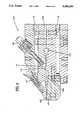
- FIG. 1is a cross-section view of the side of a die of the preferred embodiment of the invention.
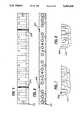
- FIG. 2is a front plan view of the die of FIG. 1;
- FIG. 3is a cross-section view of a portion of the top of the die of FIG. 1;
- FIG. 4is an enlarged cross-section view of the side of the die of FIG. 1;
- FIG. 5is a cross-section of the top of the lower die lip
- FIG. 6is a cross-section of the front of the lower die lip
- FIG. 7is an enlarged view of the groove for one of the closure elements of FIGS. 5 and 6;
- FIG. 8is an enlarged view of the groove for another closure element of FIGS. 5 and 6;
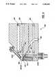
- FIG. 9is an enlarged cross-section view of the side of a multi-manifold die
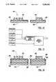
- FIG. 10shows a cross-section of a film with integrally formed closure elements of a different extrudate, according to an illustrative embodiment of this invention
- FIG. 11is a schematic view of a co-extrusion feed block coupled with a multi-manifold die, the co-extrusion feed block being fed by three extruders;
- FIG. 12shows a cross-section of a multi-layer film with integrally formed closure elements of a different extrudate, according to a further embodiment of the present invention.
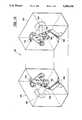
- FIG. 13is a perspective view of two plates used to form the co-extrusion feed block of FIG. 11;
- FIG. 14is a schematic view of a co-extrusion feed block coupled with a multi-manifold die, the co-extrusion feed block being fed by two extruders;
- FIG. 15shows a cross-section of a multi-layer film with integrally formed closure elements, according to an alternative embodiment of this invention.
- FIGS. 1 and 4illustrate a die 100 used in the cast film die process of the invention having a rear channel 102 where the plastic, resin or extrudate is injected from an extrusion apparatus (not shown).
- the extrudateis maintained in a fluid state by heater elements 118 extending into the die from the rear.
- the extrudateflows through the rear channel 102 to the manifold 104, best seen in FIG. 3, where it spreads out laterally across the die, filling the die. Then it flows under a choker bar 114 and into slot 106 where it becomes thinned before it passes through a space defined by an upper die lip 108 and a lower die lip 110 to be taken up by a chill roll or water bath in the conventional manner. If a water bath is used, the water is then stripped by conventional means. Thereafter, the film is folded, the closure elements are mated, and the film is sealed at bag side seams and divided into individual bags.
- the upper die lip 108has a lower surface that is substantially flat.
- the lower die lip 110has an upper surface that is substantially flat except for grooves, 200, 202 formed in the upper surface for extrusion of complementary closure elements, as shown in FIGS. 5 and 6.
- the extrudateas it flows from the manifold 104 and through slot 106, will fill the grooves 200 and 202 in the lower die lip 110 so that closure elements integral with the film are formed within the die.
- additional cavities/reservoirs(not shown) can be included to support the flow through grooves 200 and 202.
- the lower die lip 110is removable so that alternative die lips having grooves 200, 202 for the closure elements which are located in a different position, or having a different configuration, can be used.
- FIGS. 7 and 8show greatly enlarged views of the grooves 200 and 202, respectively.
- other shapes and configurations of the closure elementsmay be used.
- the die 100is also provided with an upper lip adjusting screw 112 for the upper die lip 108.
- the lip adjusting screw 112is used to vary the space between the upper die lip 108 and the lower die lip 110 so that the thickness of the film exiting the die can be varied.
- a choker bar 114protrudes downward and extends laterally across the manifold 104.
- the choker bar 114can be raised and lowered by a series of adjusting screws 116. In this way, the choker bar 114 controls the amount of extrudate passing under it causing the extrudate to evenly spread across the manifold 104. It will be appreciated that when the choker bar 114 is fully lowered, the flow of extrudate will be completely stopped.
- the choker bar 114will have gaps 115 formed at a position corresponding to the location of the grooves 200, 202 so that more extrudate will flow to the grooves.
- the die arrangement disclosed hereinis adapted to accommodate the use of separate resins, having different characteristics, for forming the closure elements and the film used to form the reclosable bags.
- a separate resincan be fed into the extrusion die just upstream from die grooves 620, 622 (comparable to the die grooves 200 and 202) by using a multi-manifold die 600 having a pair of slots 606 and 607 through which the resins may be co-extruded without being mixed together.
- the product resulting from such an arrangementis shown in FIG. 10.
- the product 400 shown thereinincludes closure elements 402 and 404 and a base layer 405 made out of a separate resin having different characteristics than the resin used to form a film 406.
- the first resinwhich is used to form the film 406, is injected into a first channel 602.
- the first resinflows through the first channel 602 to a first manifold 604, and is then laminally extruded through a first slot 606 in the multi-manifold die 600.
- a second resinwhich is used to form the closure elements 402 and 404 and the base layer 405, is injected into a second channel 603.
- the second resinflows through the second channel 603 to a second manifold 605, and is then laminally extruded through a second slot 607 in the die 600 by being fed upstream of the die grooves 620 and 622 at a feeding junction 614.
- the first and second resinswhich combine at the feeding junction 614, subsequently pass through a space defined by an upper die lip 608 and a lower die lip 610.
- the first resinforms the film 406, while the second resin fills the die grooves 620 and 622 to form the closure elements 402 and 404.
- the second resinflows outside the die grooves to form the base layer 405.
- the resulting productis as depicted in FIG. 10.
- the multi-manifold die 600includes heater elements 618, extending into the die 600 from the rear, for maintaining the first and second resins in a fluid state.
- the die 600is provided with an upper lip adjusting screw 612A for varying the space between the upper die lip 608 and the lower die lip 610 so that the thickness of the film exiting the die 600 can be varied.
- the die 600is provided with a choker bar 612B for varying the thickness of a downstream portion of the second slot 607. This allows one to vary the thickness of the second resin passing into the space between the upper die lip 608 and the lower die lip 610.
- the above arrangementis particularly advantageous where it is desired to form a reclosable bag having more than one film layer, with resulting film walls having special properties such as physical strength, ability to be colored and imprinted, etc.
- one type of resin which is particularly suited for profile extrusionsuch as a particular grade of polyethylene
- a different resinsuch as nylon
- a resin having the capability of being imprinted or coloredmay also be used for the additional layers.
- the additional layers of filmare best formed by injecting the desired resins into corresponding slots of a co-extrusion feed block. After exiting the co-extrusion feed block in a three-layered laminar flow, the flow is injected into a multi-manifold die, such as the die 600 shown in FIG. 9, so that it can be combined with another resin used to form the closure elements and the first inside layer of film.
- a multi-manifold diesuch as the die 600 shown in FIG. 9, so that it can be combined with another resin used to form the closure elements and the first inside layer of film.
- the product 500 realized from such a processis illustrated in FIG. 12.
- the closure elements 502, 504, as well as the inside layer of film 505,are all formed of the same resin.
- the closure elements 502, 504 and the associated web or inside film layer 505are formed using extruder 4 which is linked directly to the multi-manifold die through a separate plenum or manifold (not shown).
- additional layers of film 506, 508, 510, etc.may also be formed as required.
- These film layersare formed by using corresponding extruders (extruders 1, 2, and 3 in FIG. 11) which operate through the co-extrusion feed block in conjunction with the multi-manifold die. The arrangement, thus, provides the additional film layers formed of desired resins to realize a bag having multiple film layers.
- FIG. 13illustrates a co-extrusion feed block 700 which can be used to form the outer layers of film 506, 508, and 510.
- the co-extrusion feed block 700is formed from two plates 720, 722 which are attached to each other using an attaching means such as screws or bolts.
- a first resin, which is used to form the film layer 506,is injected into a first channel 702 and is laminally extruded through a first slot 704 in the feed block 700.
- a second resinwhich is used to form the film layer 508, is injected into a second channel 706 and is laminally extruded through a second slot 708; and a third resin, which is used to form the film layer 510, is injected into a third channel 710 and is laminally extruded through a third slot 712.
- the three slots 704, 708, and 712meet near the front of the feed block 700 and the three resins exit the block at a rectangularly-shaped output port 714 in a three-layered laminar flow.
- the second channel 706, the second slot 708, and the output port 714are formed from the adjoining of the two plates 720, 722.
- the laminar flowwhich forms the outer film layers 506, 508, and 510, is then fed directly into the first channel 602 of the multi-manifold 600 shown in FIG. 9.
- the laminar flowis spread out by the manifold 604 and is laminally extruded through the first slot 606.
- the first slot 606keeps the laminar flow uniform in thickness and guarantees uniform flow velocity.
- a fourth resinwhich is used to form the inner film layer 505 and the closure elements 502, 504, is fed into the second channel 603 and laminally extruded through the second slot 606.
- the choker bar 612Bis adjusted so that the fourth resin is thick enough to form both the inner film layer 505 and the closure elements 502, 504.
- the fourth resincombines with the first, second, and third resins at the feeding junction 614 to form a four-layered laminar flow, and the laminar flow then passes through the space between the upper die lip 608 and the lower die lip 610.
- the upper lip screw 612Ais adjusted so that the space is sufficient for the laminar flow to pass therethrough without being distorted.
- the first, second, and third resinsform the film layers 506, 508, 510
- a part of the fourth resinforms the inner base layer 505
- another part of the fourth resinfills the die grooves 620, 622 to form the closure elements 502, 504.
- an arrangement shown by the schematic diagram in FIG. 14is used to produce a multiple layer film product 300 shown in FIG. 15.
- the product 300 in FIG. 15differs from the product 500 in FIG. 12 in that the product 300 is composed of three film layers 306, 308, and 310 while the product 500 is composed of four film layers 505, 506, 508, and 510.
- resins for forming the film layers 306, 308, and 310may be chosen to give these film layers special properties.
- the closure elements 302, 304 and the base film layer 306are formed using extruder 3, which is linked directly to the multi-manifold die through a separate plenum or manifold (not shown). At the same time, additional layers of film 308, 310, etc. may also be formed as required.
- co-extrusion feed blockis constructed with two channels for receiving two separate resins.
- the construction of a co-extrusion feed block having two channels/slotsis similar to the feed block shown in FIG. 13, except that it includes two channels/slots instead of three channels/slots.
- the two resinsare laminally extruded through two separate slots in the feed block, the slots intersecting near an output face of the feed block. The two resins exit an output port of the feed block in a two-layered laminar flow.
- the laminar flowwhich forms the film layers 308 and 310, is then fed directly into the first channel 602 of the multi-manifold 600 shown in FIG. 9 and laminally extruded through the first slot 606.
- a third resinwhich is used to form the closure elements 302, 304 and the base layer 306, is fed into the second channel 603 and laminally extruded through the second slot 606.
- the choker bar 612Bmay be adjusted to vary the thickness of the third resin flow and, in turn, vary the thickness of the base film layer 306.
- the third resincombines with the other two resins at the feeding junction 614 to form a three-layered laminar flow, and the laminar flow then passes through the space between the upper die lip 608 and the lower die lip 610.
- part of the third resinfills the die grooves 620, 622 to form the closure elements 302, 304, another part of the third resin forms the base layer 306, and the other two resins form the two film layers 308 and 310.
- the film layers 308, 310are produced by use of a co-extrusion feed block which feeds a two-layered laminar flow into one channel of the multi-manifold die 600.
- the multiple layer film product shown in FIG. 15can be produced without using a co-extrusion feed block.
- the multi-manifold die 600 shown in FIG. 9is modified to include an additional entrance channel and corresponding manifold and slot.
- the product 300 in FIG. 15is realized by injecting a separate resin into each channel of the modified multi-manifold die, and laminally extruding each separate resin through separate manifolds and slots in the die.
- the resin injected into the additional channelis used to form one of the layers 308, 310, while a separate resin injected into another channel is used to form the other of the layers 308, 310.
- the resins for forming the layers 308, 310are fed through separate channels of the modified multi-manifold die.
- a third resin injected into a third channelis used to form the closure elements 302, 304 and the base layer 306.
- the lower die liphas only one groove formed in the upper surface for extrusion of a closure element.
- a film having a complementary closure elementis produced to be mated with a film having a corresponding complementary closure element.
- the closure elementsare positioned about 1.0 inch apart and about half-way between the outer edges of the lower die lip. Thereafter, the film is sealed at the bottom and at side seams to form enclosures having closure elements in the interior. The bag material is then separated into individual bags.
Landscapes
- Engineering & Computer Science (AREA)
- Mechanical Engineering (AREA)
- Manufacturing & Machinery (AREA)
- Chemical & Material Sciences (AREA)
- Ceramic Engineering (AREA)
- Extrusion Moulding Of Plastics Or The Like (AREA)
Abstract
Description
Claims (9)
Priority Applications (2)
| Application Number | Priority Date | Filing Date | Title |
|---|---|---|---|
| US08/021,967US5284430A (en) | 1991-08-27 | 1993-02-24 | Apparatus for manufacture of integral reclosable bag |
| US08/139,179US5425911A (en) | 1991-08-27 | 1993-10-21 | Method for manufacture of integral reclosable bag |
Applications Claiming Priority (2)
| Application Number | Priority Date | Filing Date | Title |
|---|---|---|---|
| US75034891A | 1991-08-27 | 1991-08-27 | |
| US08/021,967US5284430A (en) | 1991-08-27 | 1993-02-24 | Apparatus for manufacture of integral reclosable bag |
Related Parent Applications (1)
| Application Number | Title | Priority Date | Filing Date |
|---|---|---|---|
| US75034891AContinuation-In-Part | 1991-08-27 | 1991-08-27 |
Related Child Applications (1)
| Application Number | Title | Priority Date | Filing Date |
|---|---|---|---|
| US08/139,179DivisionUS5425911A (en) | 1991-08-27 | 1993-10-21 | Method for manufacture of integral reclosable bag |
Publications (1)
| Publication Number | Publication Date |
|---|---|
| US5284430Atrue US5284430A (en) | 1994-02-08 |
Family
ID=46247155
Family Applications (2)
| Application Number | Title | Priority Date | Filing Date |
|---|---|---|---|
| US08/021,967Expired - LifetimeUS5284430A (en) | 1991-08-27 | 1993-02-24 | Apparatus for manufacture of integral reclosable bag |
| US08/139,179Expired - LifetimeUS5425911A (en) | 1991-08-27 | 1993-10-21 | Method for manufacture of integral reclosable bag |
Family Applications After (1)
| Application Number | Title | Priority Date | Filing Date |
|---|---|---|---|
| US08/139,179Expired - LifetimeUS5425911A (en) | 1991-08-27 | 1993-10-21 | Method for manufacture of integral reclosable bag |
Country Status (1)
| Country | Link |
|---|---|
| US (2) | US5284430A (en) |
Cited By (14)
| Publication number | Priority date | Publication date | Assignee | Title |
|---|---|---|---|---|
| US5411692A (en)* | 1994-04-11 | 1995-05-02 | Reynolds Consumer Products Inc. | Integral reclosable bag die assembly |
| US5709750A (en)* | 1995-03-15 | 1998-01-20 | Schiefer; Rolf | Apparatus for applying a liquid medium |
| US5762848A (en)* | 1993-04-13 | 1998-06-09 | Sencorp Systems, Inc. | Method of adjusting choke gap of plastic extruder apparatus |
| US5770240A (en)* | 1996-04-12 | 1998-06-23 | Extrusion Dies, Inc. | Extrusion die for rigid foam sheet |
| US5851566A (en)* | 1996-07-02 | 1998-12-22 | Avery Dennison | Applicator die |
| US5858096A (en)* | 1995-09-06 | 1999-01-12 | Voith Sulzer Papiermaschinen Gmbh | Application unit for the direct or indirect application of a liquid or pasty medium onto a moving material web |
| US5962041A (en)* | 1994-02-04 | 1999-10-05 | Extrusion Dies, Inc. | Dual flexible lip extrusion apparatus |
| US6663375B1 (en) | 2000-06-19 | 2003-12-16 | Extrusion Dies, Inc. | Dual flexible lip extrusion apparatus with pivoting actuation member |
| US20040237886A1 (en)* | 2001-04-20 | 2004-12-02 | Hans-Jurgen Meissner | Device and method for despensing a fluid onto a substrate moving relative to the device |
| KR100460738B1 (en)* | 1999-12-18 | 2004-12-09 | 에스케이씨 주식회사 | The Feedblock Type Die |
| WO2009062460A3 (en)* | 2007-11-15 | 2009-07-02 | Dornier Gmbh Lindauer | Slot die and installation for coating with thermoplastic coating material |
| US8992204B2 (en) | 2010-10-06 | 2015-03-31 | Nordson Corporation | Patch coating die |
| US9434098B2 (en)* | 2014-05-29 | 2016-09-06 | Samsung Electronics Co., Ltd. | Slot die for film manufacturing |
| CN110900877A (en)* | 2019-11-29 | 2020-03-24 | 湖南工业大学 | A kind of high-fill wood-plastic composite material granulation die head voltage stabilizer device |
Families Citing this family (3)
| Publication number | Priority date | Publication date | Assignee | Title |
|---|---|---|---|---|
| MXPA05012994A (en)* | 2003-06-03 | 2006-03-16 | Avery Dennison Corp | Die assembly. |
| CA2543147A1 (en)* | 2003-10-21 | 2005-05-06 | Nestec S.A. | Shredded food products and methods of producing and applying shredded food products |
| US7494333B2 (en)* | 2004-06-04 | 2009-02-24 | S.C. Johnson Home Storage, Inc. | Apparatus for forming multiple closure elements |
Citations (8)
| Publication number | Priority date | Publication date | Assignee | Title |
|---|---|---|---|---|
| US3680997A (en)* | 1970-06-29 | 1972-08-01 | Pennwalt Corp | Extrusion strip die for thermoplastic sheet |
| US3761211A (en)* | 1972-01-17 | 1973-09-25 | Crompton & Knowles Corp | Multi-layer extrusion apparatus |
| US4515647A (en)* | 1983-02-08 | 1985-05-07 | The Dow Chemical Company | Method and apparatus for forming an integral closure for a thermoplastic container |
| US4533308A (en)* | 1984-04-16 | 1985-08-06 | Peter Cloeren | Multimanifold extrusion die and coextrusion process |
| US4536362A (en)* | 1983-10-06 | 1985-08-20 | Mobil Oil Corporation | Method for producing longitudinally ribbed plastic film |
| US4669965A (en)* | 1983-09-08 | 1987-06-02 | Kabushiki Kaisha Plastic Kogaku Kenkyusho | Multi-layer extrusion die |
| US4695236A (en)* | 1984-02-15 | 1987-09-22 | Reifenhauser Gmbh & Co. Maschinenfabrik | Apparatus for continuous extrusion of a multilayer synthetic resin web |
| US5053091A (en)* | 1990-01-18 | 1991-10-01 | Packaging Innovations, Inc. | Method and apparatus for manufacturing plastic film with integral interlocking closure members incorporating shape conforming cooling shoes after extrusion |
Family Cites Families (12)
| Publication number | Priority date | Publication date | Assignee | Title |
|---|---|---|---|---|
| US3579730A (en)* | 1965-10-22 | 1971-05-25 | Steven Ausnit | Apparatus for making a web having integral interlocking rib and groove portions |
| US3815637A (en)* | 1969-08-04 | 1974-06-11 | Phillips Petroleum Co | Means for flow control of thermoplastic material |
| US3940221A (en)* | 1973-09-10 | 1976-02-24 | Welex Incorporated | Thickness control system for an extrusion die |
| US3924247A (en)* | 1974-08-21 | 1975-12-02 | Rockwell International Corp | Driver cell with memory and shift capability |
| US4295919A (en)* | 1978-12-15 | 1981-10-20 | The Dow Chemical Co. | Forming an integral closure for a thermoplastic container |
| JPS5761542A (en)* | 1980-09-30 | 1982-04-14 | Matsushita Electric Works Ltd | Plate type special form extrusion die |
| US4822539A (en)* | 1987-09-14 | 1989-04-18 | Minigrip, Inc. | Method of and apparatus for extruding bag making material having fastener profiles and alignment ribs, with reinforcing and stabilizing beam effect ridge means |
| GB8809401D0 (en)* | 1988-04-21 | 1988-05-25 | Roeder Ind Holdings | Reclosable fasteners methods & apparatus for producing fastener profiles & products incorporating same |
| JPH066322B2 (en)* | 1988-08-18 | 1994-01-26 | 昭和高分子株式会社 | Device for continuously forming a tightening chuck on a thermoplastic synthetic resin film |
| US5066444A (en)* | 1990-07-05 | 1991-11-19 | Dowbrands Inc. | Process and apparatus for reducing color contamination in the process recycle of zippered thermoplastic bags |
| US5252281A (en)* | 1992-11-12 | 1993-10-12 | Reynolds Consumer Products Inc. | Apparatus and method for manufacture of a multi-colored closure member of a closure profile |
| US5273595A (en)* | 1992-12-09 | 1993-12-28 | Reynolds Consumer Products, Inc. | Apparatus using removable profile wedges for manufacture of reclosable bag |
- 1993
- 1993-02-24USUS08/021,967patent/US5284430A/ennot_activeExpired - Lifetime
- 1993-10-21USUS08/139,179patent/US5425911A/ennot_activeExpired - Lifetime
Patent Citations (8)
| Publication number | Priority date | Publication date | Assignee | Title |
|---|---|---|---|---|
| US3680997A (en)* | 1970-06-29 | 1972-08-01 | Pennwalt Corp | Extrusion strip die for thermoplastic sheet |
| US3761211A (en)* | 1972-01-17 | 1973-09-25 | Crompton & Knowles Corp | Multi-layer extrusion apparatus |
| US4515647A (en)* | 1983-02-08 | 1985-05-07 | The Dow Chemical Company | Method and apparatus for forming an integral closure for a thermoplastic container |
| US4669965A (en)* | 1983-09-08 | 1987-06-02 | Kabushiki Kaisha Plastic Kogaku Kenkyusho | Multi-layer extrusion die |
| US4536362A (en)* | 1983-10-06 | 1985-08-20 | Mobil Oil Corporation | Method for producing longitudinally ribbed plastic film |
| US4695236A (en)* | 1984-02-15 | 1987-09-22 | Reifenhauser Gmbh & Co. Maschinenfabrik | Apparatus for continuous extrusion of a multilayer synthetic resin web |
| US4533308A (en)* | 1984-04-16 | 1985-08-06 | Peter Cloeren | Multimanifold extrusion die and coextrusion process |
| US5053091A (en)* | 1990-01-18 | 1991-10-01 | Packaging Innovations, Inc. | Method and apparatus for manufacturing plastic film with integral interlocking closure members incorporating shape conforming cooling shoes after extrusion |
Cited By (14)
| Publication number | Priority date | Publication date | Assignee | Title |
|---|---|---|---|---|
| US5762848A (en)* | 1993-04-13 | 1998-06-09 | Sencorp Systems, Inc. | Method of adjusting choke gap of plastic extruder apparatus |
| US5962041A (en)* | 1994-02-04 | 1999-10-05 | Extrusion Dies, Inc. | Dual flexible lip extrusion apparatus |
| US5411692A (en)* | 1994-04-11 | 1995-05-02 | Reynolds Consumer Products Inc. | Integral reclosable bag die assembly |
| US5709750A (en)* | 1995-03-15 | 1998-01-20 | Schiefer; Rolf | Apparatus for applying a liquid medium |
| US5858096A (en)* | 1995-09-06 | 1999-01-12 | Voith Sulzer Papiermaschinen Gmbh | Application unit for the direct or indirect application of a liquid or pasty medium onto a moving material web |
| US5770240A (en)* | 1996-04-12 | 1998-06-23 | Extrusion Dies, Inc. | Extrusion die for rigid foam sheet |
| US5851566A (en)* | 1996-07-02 | 1998-12-22 | Avery Dennison | Applicator die |
| KR100460738B1 (en)* | 1999-12-18 | 2004-12-09 | 에스케이씨 주식회사 | The Feedblock Type Die |
| US6663375B1 (en) | 2000-06-19 | 2003-12-16 | Extrusion Dies, Inc. | Dual flexible lip extrusion apparatus with pivoting actuation member |
| US20040237886A1 (en)* | 2001-04-20 | 2004-12-02 | Hans-Jurgen Meissner | Device and method for despensing a fluid onto a substrate moving relative to the device |
| WO2009062460A3 (en)* | 2007-11-15 | 2009-07-02 | Dornier Gmbh Lindauer | Slot die and installation for coating with thermoplastic coating material |
| US8992204B2 (en) | 2010-10-06 | 2015-03-31 | Nordson Corporation | Patch coating die |
| US9434098B2 (en)* | 2014-05-29 | 2016-09-06 | Samsung Electronics Co., Ltd. | Slot die for film manufacturing |
| CN110900877A (en)* | 2019-11-29 | 2020-03-24 | 湖南工业大学 | A kind of high-fill wood-plastic composite material granulation die head voltage stabilizer device |
Also Published As
| Publication number | Publication date |
|---|---|
| US5425911A (en) | 1995-06-20 |
Similar Documents
| Publication | Publication Date | Title |
|---|---|---|
| US5284430A (en) | Apparatus for manufacture of integral reclosable bag | |
| EP0201617B1 (en) | Method and apparatus for continuously co-extruding a sheet | |
| US4405547A (en) | Method of coextruding diverse materials | |
| US4426344A (en) | Coextrusion process and apparatus for manufacturing multi-layered flat films of thermoplastic materials | |
| EP0050476B1 (en) | Coextrusion device and method | |
| US5087488A (en) | Method and apparatus for forming a plastic article with an overlay of varying thickness having a shaded color appearance | |
| EP0161812B1 (en) | Multimanifold extrusion die and coextrusion process | |
| US4118166A (en) | Extrusion apparatus | |
| US5120484A (en) | Coextrusion nozzle and process | |
| US4600550A (en) | Coextrusion process for overcoming the curtaining effect | |
| US3464087A (en) | Multiple-channel extrusion die for the production of multilayer thermoplastic sheet materials | |
| WO1986002316A1 (en) | Two-color sheet, article, method and apparatus | |
| GB2209701A (en) | Extruding bag-making film having fastener profiles and alignment ribs | |
| US3334382A (en) | Extrusion adapter | |
| EP0294213A2 (en) | Edge-laminating apparatus and process | |
| US4483812A (en) | Valve plate and feedblock design for co-extrusion apparatus and co-extrusion process using same | |
| US5045264A (en) | Method and apparatus for making extruded plastic film with strips embedded therein of a second thermoplastic material | |
| CN107175804A (en) | It is coextruded joint | |
| US4187270A (en) | Extrusion apparatus | |
| CA1140716A (en) | Extruding die apparatus for producing a plastic closure strip | |
| US4611987A (en) | Apparatus for forming multilayer thermoplastic resin extrusions | |
| US5273595A (en) | Apparatus using removable profile wedges for manufacture of reclosable bag | |
| EP0834388A1 (en) | Adjustable coextrusion feedblock | |
| US3941551A (en) | Apparatus involving a centerplate and a heat sink between multiple flat extrusion streams | |
| US7494333B2 (en) | Apparatus for forming multiple closure elements |
Legal Events
| Date | Code | Title | Description |
|---|---|---|---|
| AS | Assignment | Owner name:REYNOLDS CONSUMER PRODUCTS, INC., WISCONSIN Free format text:ASSIGNMENT OF ASSIGNORS INTEREST;ASSIGNOR:TOMIC, MLADOMIR ET AL.;REEL/FRAME:006532/0644 Effective date:19930215 | |
| STCF | Information on status: patent grant | Free format text:PATENTED CASE | |
| FEPP | Fee payment procedure | Free format text:PAYOR NUMBER ASSIGNED (ORIGINAL EVENT CODE: ASPN); ENTITY STATUS OF PATENT OWNER: LARGE ENTITY | |
| FPAY | Fee payment | Year of fee payment:4 | |
| REMI | Maintenance fee reminder mailed | ||
| FPAY | Fee payment | Year of fee payment:8 | |
| SULP | Surcharge for late payment | Year of fee payment:7 | |
| FPAY | Fee payment | Year of fee payment:12 | |
| AS | Assignment | Owner name:CREDIT SUISSE, SYDNEY BRANCH, AUSTRALIA Free format text:NOTICE AND CONFIRMATION OF GRANT OF SECURITY INTEREST IN PATENTS;ASSIGNOR:REYNOLDS CONSUMER PRODUCTS, INC.;REEL/FRAME:020828/0496 Effective date:20080229 Owner name:CREDIT SUISSE, SYDNEY BRANCH,AUSTRALIA Free format text:NOTICE AND CONFIRMATION OF GRANT OF SECURITY INTEREST IN PATENTS;ASSIGNOR:REYNOLDS CONSUMER PRODUCTS, INC.;REEL/FRAME:020828/0496 Effective date:20080229 | |
| AS | Assignment | Owner name:REYNOLDS CONSUMER PRODUCTS, INC., VIRGINIA Free format text:TERMINATION AND RELEASE OF SECURITY INTEREST;ASSIGNOR:CREDIT SUISSE, SYDNEY BRANCH;REEL/FRAME:023546/0309 Effective date:20091105 Owner name:REYNOLDS CONSUMER PRODUCTS, INC.,VIRGINIA Free format text:TERMINATION AND RELEASE OF SECURITY INTEREST;ASSIGNOR:CREDIT SUISSE, SYDNEY BRANCH;REEL/FRAME:023546/0309 Effective date:20091105 | |
| AS | Assignment | Owner name:THE BANK OF NEW YORK MELLON, NEW YORK Free format text:SECURITY AGREEMENT;ASSIGNORS:CLOSURE SYSTEMS INTERNATIONAL INC.;REYNOLDS CONSUMER PRODUCTS INC.;REYNOLDS FOIL INC.;AND OTHERS;REEL/FRAME:023574/0312 Effective date:20091105 Owner name:THE BANK OF NEW YORK MELLON,NEW YORK Free format text:SECURITY AGREEMENT;ASSIGNORS:CLOSURE SYSTEMS INTERNATIONAL INC.;REYNOLDS CONSUMER PRODUCTS INC.;REYNOLDS FOIL INC.;AND OTHERS;REEL/FRAME:023574/0312 Effective date:20091105 | |
| AS | Assignment | Owner name:REYNOLDS CONSUMER PRODUCTS LLC (F/K/A REYNOLDS FOIL INC.), ILLINOIS Free format text:RELEASE OF SECURITY INTEREST IN CERTAIN PATENT COLLATERAL;ASSIGNOR:THE BANK OF NEW YORK MELLON, AS COLLATERAL AGENT;REEL/FRAME:051798/0051 Effective date:20200204 Owner name:REYNOLDS PRESTO PRODUCTS INC. (F/K/A REYNOLDS CONSUMER PRODUCTS, INC.), ILLINOIS Free format text:RELEASE OF SECURITY INTEREST IN CERTAIN PATENT COLLATERAL;ASSIGNOR:THE BANK OF NEW YORK MELLON, AS COLLATERAL AGENT;REEL/FRAME:051798/0051 Effective date:20200204 |