US5284129A - Swivel ring surgical retractor - Google Patents
Swivel ring surgical retractorDownload PDFInfo
- Publication number
- US5284129A US5284129AUS07/936,970US93697092AUS5284129AUS 5284129 AUS5284129 AUS 5284129AUS 93697092 AUS93697092 AUS 93697092AUS 5284129 AUS5284129 AUS 5284129A
- Authority
- US
- United States
- Prior art keywords
- swivel
- retractor
- fixed portion
- ring
- sunburst
- Prior art date
- Legal status (The legal status is an assumption and is not a legal conclusion. Google has not performed a legal analysis and makes no representation as to the accuracy of the status listed.)
- Expired - Lifetime
Links
- 241001354471PseudobahiaSpecies0.000claimsabstractdescription18
- 208000002847Surgical WoundDiseases0.000claimsdescription4
- 238000000926separation methodMethods0.000claims1
- 238000001356surgical procedureMethods0.000description7
- 230000007246mechanismEffects0.000description5
- 210000004556brainAnatomy0.000description3
- 238000012084abdominal surgeryMethods0.000description2
- 210000001015abdomenAnatomy0.000description1
- 230000003187abdominal effectEffects0.000description1
Images


Classifications
- A—HUMAN NECESSITIES
- A61—MEDICAL OR VETERINARY SCIENCE; HYGIENE
- A61B—DIAGNOSIS; SURGERY; IDENTIFICATION
- A61B17/00—Surgical instruments, devices or methods
- A61B17/02—Surgical instruments, devices or methods for holding wounds open, e.g. retractors; Tractors
- A61B17/0293—Surgical instruments, devices or methods for holding wounds open, e.g. retractors; Tractors with ring member to support retractor elements
- Y—GENERAL TAGGING OF NEW TECHNOLOGICAL DEVELOPMENTS; GENERAL TAGGING OF CROSS-SECTIONAL TECHNOLOGIES SPANNING OVER SEVERAL SECTIONS OF THE IPC; TECHNICAL SUBJECTS COVERED BY FORMER USPC CROSS-REFERENCE ART COLLECTIONS [XRACs] AND DIGESTS
- Y10—TECHNICAL SUBJECTS COVERED BY FORMER USPC
- Y10T—TECHNICAL SUBJECTS COVERED BY FORMER US CLASSIFICATION
- Y10T403/00—Joints and connections
- Y10T403/32—Articulated members
- Y10T403/32254—Lockable at fixed position
- Y10T403/32262—At selected angle
Definitions
- the inventionrelates to the field of surgical appliances and particularly to a device that is used to mount surgical retractors in a position over the body of the patient and more particularly over the head of the patient during a surgical procedure.
- Surgical retractorsare used for holding tissue, at the edge of a surgical incision or wound, away from the field of the operation.
- One particular type of retractoremploys a support mechanism to which the actual retractor elements can be attached. This type of retractor is commonly used in abdominal surgery and also in brain surgery. In abdominal surgery the retractor is positioned over the abdomen of the patient. Moveable retractor arms are positioned to hold body tissue surrounding the incision away from the field of the operation. In brain surgery, the retractor is similarly used to keep tissue away from the field of the surgical procedure.
- a particular type of retractor used in both abdominal and brain surgeryis a retractor which has a frame to which individual arms, having retractor blades at their ends, can be attached.
- the positioning of the retractor on the framecan be adjusted so that the retractor can be used to adjust the retractor blades in the proper position for different types of surgery.
- retractorsexamples include those disclosed in U.S. Pat. Nos. 1,839,726; 2,594,086; 3,522,799; 4,099,521; 4,254,763 and 4,457,300. All of these retractors include a frame to which different types of retractor elements can be attached. The retractor blades themselves can be adjusted to position the retractor blades in a proper location to keep tissue away from the operative field during the surgical procedure.
- the retractor disclosed in U.S. Pat. No. 4,099,521is a ring shape retractor in which a portion of the ring is removable.
- the retractor disclosed in U.S. Pat. No. 4,457,300is ring shaped and has a dovetail slot around the outer circumference of the ring.
- the disclosure of U.S. Pat. No. 4,457,300is incorporated herein by reference.
- Retractor elementscan be fitted into the dovetail slot and secured in various positions.
- An improvement to the ring shown in U.S. Pat. No. 4,457,300provides a two component ring which has a portion which can swivel 180° to provide greater access to the operative site if desired.
- the swivel portion of the ringis attached to the fixed portion with a pair of pivot mechanisms which fit into the dovetail slot around the outer circumference of the ring.
- sunburst clampon one side of the ring which may be disengaged to allow the swivel portion of the ring to rotate.
- the swivel portion of the ringalso can be removed from the fixed portion of the ring by the removal of the pivot mechanisms from the dovetail slot on opposite sides of the fixed portion of the ring.
- the present inventionprovides an improved swivel ring retractor mechanism which provides the ability to swivel a portion of the ring in an 180° arc as well as to readily remove the swivel portion of the ring from the fixed portion of the ring if the removal of a portion of the ring is desired to provide greater access to the surgical field.
- the swivel portion of the retractor ringcan be removed by one person without the necessity of employing any tools.
- the swivel portion of the ringis attached to the fixed portion of the ring with a removable pin which is centered in a sunburst clamp and has a bore into which a pin located on the fixed portion of the ring can be inserted.
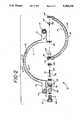
- FIG. 1is a perspective view of the retractor ring of the present invention.
- FIG. 2is a bottom plan view partially in section of a disassembled ring of the present invention.
- FIG. 3is a perspective view of the shoulder pin used to support the swivel portion of the ring of the present invention.
- FIG. 4is a cross sectional view of the ring structure showing the dovetail groove as taken along line 4--4 of FIG. 2.
- the retractor ring of the present inventioncomprises a generally circular ring 10 which is made in two parts, a fixed portion 11 and a swivel portion 12.
- the fixed portion 11has two support arms 13 that extend outwardly from the circumference of the ring.
- a support mechanism of this typeis shown in detail in U.S. Pat. No. 4,457,300 mentioned above.
- Around the outer circumference of the ringthere is a dovetail slot 15 which extends substantially around the circumference of each portion of the ring.
- each portion of the ringthere is an opening 16, preferably in the lower surface of each portion of the ring, to allow fixtures which secure the retractor blades to be inserted into the dovetail slot.
- the ringhas a swivel portion 12 which is capable of swiveling 180° along an axis between the threaded shaft 19 and the outwardly directed pin 23 on the fixed portion 11 of the ring and which is aligned with the shaft 19.
- the pin 23has at least one and preferably two flat shoulders 30 so that the pin can freely rotate in the bore or opening 24 of the swivel ring without binding.
- a sunburst clamping insert 28which is mated with the sunburst clamping insert 18 on the fixed portion of the ring to securely prevent the swivel portion of the ring from rotating until desired.
- Second boss 40 of the swivel portion of the ringhas an internally threaded bore 31 in its center.
- the threads in the boreare matched with the threads on the shaft 19.
- There is a second bore 24 on the swivel portion of the ringwhich is aligned with the threaded bore 31 to receive the pin 23 on the fixed portion of the ring.
- the ringis mounted on the supports by inserting a ball into the bushings 14 in the support arms 13.
- a locking ringis used to secure the support to the support arm.
- Retractors of the type shown in U.S. Pat. No. 4,457,300can be fitted into the dovetail slot and positioned around the surgical incision.
- the retractor bladesare held in the slot 15 by dovetail clamps which can be moved to position the retractors in the position desired by the surgeon.
- the handle 25 on the shaft 19can be rotated to remove the threaded end of the shaft from the threads in the swivel portion of the swivel ring. This allows the sunbursts clamping inserts to disengage and the swivel portion of the ring can rotate around an axis made up of the shaft 19 and the pin 23.
- the handle 25can be rotated to totally remove the threaded end 27 of the shaft from the sunburst insert 28 in the swivel portion of the ring.
- the pin 23will then disengage from the bore 24 and the swivel portion of the retractor ring can be totally removed from the fixed portion of the ring.
Landscapes
- Health & Medical Sciences (AREA)
- Life Sciences & Earth Sciences (AREA)
- Surgery (AREA)
- Heart & Thoracic Surgery (AREA)
- Engineering & Computer Science (AREA)
- Biomedical Technology (AREA)
- Nuclear Medicine, Radiotherapy & Molecular Imaging (AREA)
- Medical Informatics (AREA)
- Molecular Biology (AREA)
- Animal Behavior & Ethology (AREA)
- General Health & Medical Sciences (AREA)
- Public Health (AREA)
- Veterinary Medicine (AREA)
- Surgical Instruments (AREA)
Abstract
Description
Claims (3)
Priority Applications (1)
| Application Number | Priority Date | Filing Date | Title |
|---|---|---|---|
| US07/936,970US5284129A (en) | 1992-08-28 | 1992-08-28 | Swivel ring surgical retractor |
Applications Claiming Priority (1)
| Application Number | Priority Date | Filing Date | Title |
|---|---|---|---|
| US07/936,970US5284129A (en) | 1992-08-28 | 1992-08-28 | Swivel ring surgical retractor |
Publications (1)
| Publication Number | Publication Date |
|---|---|
| US5284129Atrue US5284129A (en) | 1994-02-08 |
Family
ID=25469281
Family Applications (1)
| Application Number | Title | Priority Date | Filing Date |
|---|---|---|---|
| US07/936,970Expired - LifetimeUS5284129A (en) | 1992-08-28 | 1992-08-28 | Swivel ring surgical retractor |
Country Status (1)
| Country | Link |
|---|---|
| US (1) | US5284129A (en) |
Cited By (37)
| Publication number | Priority date | Publication date | Assignee | Title |
|---|---|---|---|---|
| US5400774A (en)* | 1993-11-08 | 1995-03-28 | Villalta; Josue J. | Four blade medical retractor |
| US5529358A (en)* | 1994-09-30 | 1996-06-25 | Ohio Medical Instrument Company | Bifurcated surgical retractor |
| US5891157A (en)* | 1994-09-30 | 1999-04-06 | Ohio Medical Instrument Company, Inc. | Apparatus for surgical stereotactic procedures |
| USD412576S (en)* | 1998-07-30 | 1999-08-03 | Applied Medical Technologies, Inc. | Tissue retractor frame |
| US6659945B2 (en) | 2001-06-29 | 2003-12-09 | Depuy Orthopaedics, Inc. | Self retaining retractor ring |
| US20030229338A1 (en)* | 2000-11-03 | 2003-12-11 | Irion Klaus M. | Device for holding and positioning an endoscopic instrument |
| US20050080319A1 (en)* | 2001-04-20 | 2005-04-14 | Dinkler Ii Charles E. | Radiolucent retractor and related components |
| US20050159650A1 (en)* | 2003-12-18 | 2005-07-21 | Depuy Spine, Inc. | Surgical methods and surgical kits |
| US20050215866A1 (en)* | 2004-03-25 | 2005-09-29 | Depuy Spine, Inc. | Surgical retractor positioning device |
| US20060084900A1 (en)* | 2004-10-15 | 2006-04-20 | Schule Edgar F | Method and apparatus for attaching accessories to a surgical fixture |
| US20070156023A1 (en)* | 2006-01-05 | 2007-07-05 | Depuy Spine, Inc. | Non-rigid surgical retractor |
| US20070238932A1 (en)* | 2006-03-08 | 2007-10-11 | Jones Robert J | Surgical retractor and retractor assembly |
| US7730563B1 (en) | 2004-03-29 | 2010-06-08 | Frederick Sklar | Head support and stabilization system |
| US20100179601A1 (en)* | 2006-06-29 | 2010-07-15 | Jung Edward K Y | Threadless position augmenting mechanism |
| US7758501B2 (en) | 2006-01-04 | 2010-07-20 | Depuy Spine, Inc. | Surgical reactors and methods of minimally invasive surgery |
| US20100249847A1 (en)* | 2006-06-29 | 2010-09-30 | Searete Llc, A Limited Liability Corporation Of The State Of Delaware | Position augmenting mechanism |
| US7918792B2 (en) | 2006-01-04 | 2011-04-05 | Depuy Spine, Inc. | Surgical retractor for use with minimally invasive spinal stabilization systems and methods of minimally invasive surgery |
| US20110168184A1 (en)* | 2010-01-11 | 2011-07-14 | Sklar Frederick H | Pediatric Headrest for Skull Stabilization and Method for Use of Same |
| US7981031B2 (en) | 2006-01-04 | 2011-07-19 | Depuy Spine, Inc. | Surgical access devices and methods of minimally invasive surgery |
| DE102010006575A1 (en)* | 2010-02-02 | 2011-08-04 | Adeor Medical Technologies GmbH, 82049 | Ring retractor for head mount of head mount device for neurosurgery, has semi-circular ring segment with oval cross-section, where both ring segments are connected with each other by adjustable hinges fixable by nut |
| US8721538B2 (en) | 2010-05-10 | 2014-05-13 | St. Louis University | Distractor |
| US20140215767A1 (en)* | 2013-01-15 | 2014-08-07 | Magpul Industries Corp. | D-Ring for Sling |
| US8844536B1 (en) | 2010-08-24 | 2014-09-30 | Pro Med Instruments Gmbh | Locking apparatus for a head fixation device |
| US8894029B2 (en) | 2011-09-30 | 2014-11-25 | Specialty Surgical Instrumentation, Inc. | Retractor ring holder |
| US9084591B2 (en) | 2012-10-23 | 2015-07-21 | Neurostructures, Inc. | Retractor |
| US9216125B2 (en) | 2011-07-22 | 2015-12-22 | Frederick H. Sklar | Surgical head holder and surgical accessories for use with same |
| US9216126B2 (en) | 2012-08-28 | 2015-12-22 | Pro Med Instruments Gmbh | Table adapter with joint assembly |
| US9402692B2 (en) | 2011-10-02 | 2016-08-02 | Pro Med Instruments Gmbh | Head fixation device and apparatus for securing components thereto |
| RU188013U1 (en)* | 2018-09-24 | 2019-03-26 | Общество с ограниченной ответственностью научно-производственная фирма "Кварц" (ООО НПФ "Кварц") | Detachable ring retractor |
| US10682196B2 (en) | 2011-10-02 | 2020-06-16 | Pro Med Instruments Gmbh | Head fixation device and apparatus for securing components thereto |
| KR20200129581A (en)* | 2019-05-09 | 2020-11-18 | 가톨릭대학교 산학협력단 | Brain operation device with towing part |
| US10918371B2 (en) | 2019-04-03 | 2021-02-16 | Brain Innovations Llc | Apparatus and method for retracting brain tissue during brain surgery |
| US11123056B2 (en) | 2019-05-23 | 2021-09-21 | Thompson Surgical Instruments, Inc. | Ring retractor system |
| RU217780U1 (en)* | 2022-10-25 | 2023-04-17 | Антон Петрович Комаров | Annular seating device for a mechanical prosthetic heart valve |
| US11986426B1 (en) | 2022-11-07 | 2024-05-21 | Frederick H. Sklar | Base station assembly for an operating room table |
| US12082981B2 (en) | 2022-11-07 | 2024-09-10 | Frederick H. Sklar | Surgical armrest |
| US12083052B2 (en) | 2022-11-07 | 2024-09-10 | Frederick H. Sklar | Surgical universal headrest including skull pin holder assembly |
Citations (11)
| Publication number | Priority date | Publication date | Assignee | Title |
|---|---|---|---|---|
| US1839726A (en)* | 1930-08-01 | 1932-01-05 | Hubert R Arnold | Circular retractor |
| US2594086A (en)* | 1950-04-29 | 1952-04-22 | David P Smith | Table supported abdominal retractor |
| US3129706A (en)* | 1962-11-13 | 1964-04-21 | Jr Walker Reynolds | Surgical retractor |
| US3522799A (en)* | 1967-06-21 | 1970-08-04 | William K Gauthier | Surgical retractor device |
| US4099521A (en)* | 1975-06-16 | 1978-07-11 | Nestor Engineering Associates, Inc. | Surgical retractor adjustable mounting apparatus |
| US4254763A (en)* | 1979-06-07 | 1981-03-10 | Codman & Shurtleff, Inc. | Surgical retractor assembly |
| US4434791A (en)* | 1982-03-15 | 1984-03-06 | Humboldt Products Corp. | Surgical retractor array system |
| US4457300A (en)* | 1982-06-07 | 1984-07-03 | Ohio Medical Instrument Co., Inc. | Surgical retractor |
| US5009124A (en)* | 1986-02-13 | 1991-04-23 | Ae Plc | Wrist pin |
| US5201742A (en)* | 1991-04-16 | 1993-04-13 | Hasson Harrith M | Support jig for a surgical instrument |
| US5214815A (en)* | 1992-08-28 | 1993-06-01 | Codman & Shurtleff, Inc. | Surgical headrest with removable foam pad |
- 1992
- 1992-08-28USUS07/936,970patent/US5284129A/ennot_activeExpired - Lifetime
Patent Citations (11)
| Publication number | Priority date | Publication date | Assignee | Title |
|---|---|---|---|---|
| US1839726A (en)* | 1930-08-01 | 1932-01-05 | Hubert R Arnold | Circular retractor |
| US2594086A (en)* | 1950-04-29 | 1952-04-22 | David P Smith | Table supported abdominal retractor |
| US3129706A (en)* | 1962-11-13 | 1964-04-21 | Jr Walker Reynolds | Surgical retractor |
| US3522799A (en)* | 1967-06-21 | 1970-08-04 | William K Gauthier | Surgical retractor device |
| US4099521A (en)* | 1975-06-16 | 1978-07-11 | Nestor Engineering Associates, Inc. | Surgical retractor adjustable mounting apparatus |
| US4254763A (en)* | 1979-06-07 | 1981-03-10 | Codman & Shurtleff, Inc. | Surgical retractor assembly |
| US4434791A (en)* | 1982-03-15 | 1984-03-06 | Humboldt Products Corp. | Surgical retractor array system |
| US4457300A (en)* | 1982-06-07 | 1984-07-03 | Ohio Medical Instrument Co., Inc. | Surgical retractor |
| US5009124A (en)* | 1986-02-13 | 1991-04-23 | Ae Plc | Wrist pin |
| US5201742A (en)* | 1991-04-16 | 1993-04-13 | Hasson Harrith M | Support jig for a surgical instrument |
| US5214815A (en)* | 1992-08-28 | 1993-06-01 | Codman & Shurtleff, Inc. | Surgical headrest with removable foam pad |
Non-Patent Citations (2)
| Title |
|---|
| Codman Surgical Products Catalog, 1990, p. N 120.* |
| Codman Surgical Products Catalog, 1990, p. N-120. |
Cited By (67)
| Publication number | Priority date | Publication date | Assignee | Title |
|---|---|---|---|---|
| US5400774A (en)* | 1993-11-08 | 1995-03-28 | Villalta; Josue J. | Four blade medical retractor |
| US5529358A (en)* | 1994-09-30 | 1996-06-25 | Ohio Medical Instrument Company | Bifurcated surgical retractor |
| US5891157A (en)* | 1994-09-30 | 1999-04-06 | Ohio Medical Instrument Company, Inc. | Apparatus for surgical stereotactic procedures |
| USD412576S (en)* | 1998-07-30 | 1999-08-03 | Applied Medical Technologies, Inc. | Tissue retractor frame |
| US6966876B2 (en)* | 2000-11-03 | 2005-11-22 | Karl Storz Gmbh & Co. Kg | Device for holding and positioning an endoscopic instrument |
| US20030229338A1 (en)* | 2000-11-03 | 2003-12-11 | Irion Klaus M. | Device for holding and positioning an endoscopic instrument |
| US20050080319A1 (en)* | 2001-04-20 | 2005-04-14 | Dinkler Ii Charles E. | Radiolucent retractor and related components |
| US7232411B2 (en)* | 2001-04-20 | 2007-06-19 | Integra Lifesciences Corporation | Radiolucent retractor and related components |
| US6659945B2 (en) | 2001-06-29 | 2003-12-09 | Depuy Orthopaedics, Inc. | Self retaining retractor ring |
| US20090018400A1 (en)* | 2003-12-18 | 2009-01-15 | Depuy Spine, Inc. | Surgical retractor systems and illuminated cannulae |
| US20050159650A1 (en)* | 2003-12-18 | 2005-07-21 | Depuy Spine, Inc. | Surgical methods and surgical kits |
| US8038611B2 (en) | 2003-12-18 | 2011-10-18 | Depuy Spine, Inc. | Surgical methods and surgical kits |
| US8602984B2 (en) | 2003-12-18 | 2013-12-10 | DePuy Synthes Products, LLC | Surgical retractor systems and illuminated cannulae |
| US10869657B2 (en) | 2003-12-18 | 2020-12-22 | DePuy Synthes Products, Inc. | Surgical retractor systems and illuminated cannulae |
| US8622897B2 (en) | 2003-12-18 | 2014-01-07 | DePuy Synthes Products, LLC | Surgical methods and surgical kits |
| WO2005094695A3 (en)* | 2004-03-25 | 2005-11-10 | Depuy Spine Inc | Surgical retractor positioning device |
| US7435219B2 (en) | 2004-03-25 | 2008-10-14 | Depuy Spine, Inc. | Surgical retractor positioning device |
| US20090018401A1 (en)* | 2004-03-25 | 2009-01-15 | Depuy Spine, Inc. | Surgical retractor positioning device |
| US20050215866A1 (en)* | 2004-03-25 | 2005-09-29 | Depuy Spine, Inc. | Surgical retractor positioning device |
| US7730563B1 (en) | 2004-03-29 | 2010-06-08 | Frederick Sklar | Head support and stabilization system |
| US20060084900A1 (en)* | 2004-10-15 | 2006-04-20 | Schule Edgar F | Method and apparatus for attaching accessories to a surgical fixture |
| US7836532B2 (en) | 2004-10-15 | 2010-11-23 | Pro Med Instruments Gmbh | Method and apparatus for attaching accessories to a surgical fixture |
| US8517935B2 (en) | 2006-01-04 | 2013-08-27 | DePuy Synthes Products, LLC | Surgical retractors and methods of minimally invasive surgery |
| US8550995B2 (en) | 2006-01-04 | 2013-10-08 | DePuy Synthes Products, LLC | Surgical access devices and methods of minimally invasive surgery |
| US20110004067A1 (en)* | 2006-01-04 | 2011-01-06 | Connie Marchek | Surgical Retractors and Methods of Minimally Invasive Surgery |
| US7918792B2 (en) | 2006-01-04 | 2011-04-05 | Depuy Spine, Inc. | Surgical retractor for use with minimally invasive spinal stabilization systems and methods of minimally invasive surgery |
| US7758501B2 (en) | 2006-01-04 | 2010-07-20 | Depuy Spine, Inc. | Surgical reactors and methods of minimally invasive surgery |
| US7981031B2 (en) | 2006-01-04 | 2011-07-19 | Depuy Spine, Inc. | Surgical access devices and methods of minimally invasive surgery |
| US9254126B2 (en) | 2006-01-05 | 2016-02-09 | DePuy Synthes Products, Inc. | Non-rigid surgical retractor |
| US20110213207A1 (en)* | 2006-01-05 | 2011-09-01 | Depuy Spine, Inc. | Non-rigid surgical retractor |
| US7955257B2 (en) | 2006-01-05 | 2011-06-07 | Depuy Spine, Inc. | Non-rigid surgical retractor |
| US20070156023A1 (en)* | 2006-01-05 | 2007-07-05 | Depuy Spine, Inc. | Non-rigid surgical retractor |
| US20070238932A1 (en)* | 2006-03-08 | 2007-10-11 | Jones Robert J | Surgical retractor and retractor assembly |
| US8876687B2 (en) | 2006-03-08 | 2014-11-04 | Zimmer Spine, Inc. | Surgical retractor and retractor assembly |
| US20100179601A1 (en)* | 2006-06-29 | 2010-07-15 | Jung Edward K Y | Threadless position augmenting mechanism |
| US20100249847A1 (en)* | 2006-06-29 | 2010-09-30 | Searete Llc, A Limited Liability Corporation Of The State Of Delaware | Position augmenting mechanism |
| US20100274290A1 (en)* | 2006-06-29 | 2010-10-28 | Searete Llc, A Limited Liability Corporation Of The State Of Delaware | Position augmenting mechanism |
| US20110168184A1 (en)* | 2010-01-11 | 2011-07-14 | Sklar Frederick H | Pediatric Headrest for Skull Stabilization and Method for Use of Same |
| US8646452B2 (en) | 2010-01-11 | 2014-02-11 | Frederick H. Sklar | Pediatric headrest for skull stabilization and method for use of same |
| US9211224B2 (en) | 2010-01-11 | 2015-12-15 | Frederick H. Sklar | Pediatric headrest for skull stabilization and method for use of same |
| DE102010006575A1 (en)* | 2010-02-02 | 2011-08-04 | Adeor Medical Technologies GmbH, 82049 | Ring retractor for head mount of head mount device for neurosurgery, has semi-circular ring segment with oval cross-section, where both ring segments are connected with each other by adjustable hinges fixable by nut |
| US8721538B2 (en) | 2010-05-10 | 2014-05-13 | St. Louis University | Distractor |
| US8844536B1 (en) | 2010-08-24 | 2014-09-30 | Pro Med Instruments Gmbh | Locking apparatus for a head fixation device |
| US9216125B2 (en) | 2011-07-22 | 2015-12-22 | Frederick H. Sklar | Surgical head holder and surgical accessories for use with same |
| US8894029B2 (en) | 2011-09-30 | 2014-11-25 | Specialty Surgical Instrumentation, Inc. | Retractor ring holder |
| US9402692B2 (en) | 2011-10-02 | 2016-08-02 | Pro Med Instruments Gmbh | Head fixation device and apparatus for securing components thereto |
| US10682196B2 (en) | 2011-10-02 | 2020-06-16 | Pro Med Instruments Gmbh | Head fixation device and apparatus for securing components thereto |
| US9216126B2 (en) | 2012-08-28 | 2015-12-22 | Pro Med Instruments Gmbh | Table adapter with joint assembly |
| US9084591B2 (en) | 2012-10-23 | 2015-07-21 | Neurostructures, Inc. | Retractor |
| US9157699B2 (en)* | 2013-01-15 | 2015-10-13 | Magpul Industries Corp | D-ring for sling |
| US20140215767A1 (en)* | 2013-01-15 | 2014-08-07 | Magpul Industries Corp. | D-Ring for Sling |
| RU188013U1 (en)* | 2018-09-24 | 2019-03-26 | Общество с ограниченной ответственностью научно-производственная фирма "Кварц" (ООО НПФ "Кварц") | Detachable ring retractor |
| US11653908B2 (en) | 2019-04-03 | 2023-05-23 | Brain Innovations Llc | Apparatus and method for retracting brain tissue during brain surgery |
| US10918371B2 (en) | 2019-04-03 | 2021-02-16 | Brain Innovations Llc | Apparatus and method for retracting brain tissue during brain surgery |
| KR102235685B1 (en) | 2019-05-09 | 2021-04-01 | 가톨릭대학교 산학협력단 | Brain operation device with towing part |
| KR20200129581A (en)* | 2019-05-09 | 2020-11-18 | 가톨릭대학교 산학협력단 | Brain operation device with towing part |
| US11123056B2 (en) | 2019-05-23 | 2021-09-21 | Thompson Surgical Instruments, Inc. | Ring retractor system |
| US12070200B2 (en) | 2019-05-23 | 2024-08-27 | Thompson Surgical Instruments, Inc. | Ring retractor system |
| RU217780U1 (en)* | 2022-10-25 | 2023-04-17 | Антон Петрович Комаров | Annular seating device for a mechanical prosthetic heart valve |
| US11986426B1 (en) | 2022-11-07 | 2024-05-21 | Frederick H. Sklar | Base station assembly for an operating room table |
| US12082981B2 (en) | 2022-11-07 | 2024-09-10 | Frederick H. Sklar | Surgical armrest |
| US12083052B2 (en) | 2022-11-07 | 2024-09-10 | Frederick H. Sklar | Surgical universal headrest including skull pin holder assembly |
| US12090094B2 (en) | 2022-11-07 | 2024-09-17 | Frederick H. Sklar | Surgical universal headrest including skull pin holder assembly |
| US12090093B2 (en) | 2022-11-07 | 2024-09-17 | Frederick H. Sklar | Surgical universal headrest including skull pin holder assembly |
| US12209704B2 (en) | 2022-11-07 | 2025-01-28 | Frederick H. Sklar | Base station assembly for an operating room table |
| US12345373B2 (en) | 2022-11-07 | 2025-07-01 | Frederick H. Sklar | Base station assembly for an operating room table |
| US12409090B2 (en) | 2022-11-07 | 2025-09-09 | Frederick H. Sklar | Surgical universal headrest including skull pin holder assembly |
Similar Documents
| Publication | Publication Date | Title |
|---|---|---|
| US5284129A (en) | Swivel ring surgical retractor | |
| US7294104B2 (en) | Surgical instrument holder | |
| US5167223A (en) | Heart valve retractor and sternum spreader surgical instrument | |
| US4971037A (en) | Surgical retractor support | |
| US4457300A (en) | Surgical retractor | |
| US6659945B2 (en) | Self retaining retractor ring | |
| EP3116462B1 (en) | Limb positioning system | |
| US7749163B2 (en) | Universal scissors joint apparatus | |
| US3810462A (en) | Self-retaining surgical retractor | |
| US5025780A (en) | Table mounted surgical retractor | |
| US4796846A (en) | Retaining device for a surgical instrument | |
| US5020195A (en) | Clamping device for use on a retractor support | |
| US4949707A (en) | Retractor apparatus | |
| US5908382A (en) | Minimally invasive retractor for internal mammary artery harvesting | |
| US20090105547A1 (en) | Adjustable Retractor Blade | |
| US6808493B1 (en) | Adjustable ratchet retractor support apparatus | |
| US4934809A (en) | Lens positioning device for indirect biomicroscopy of the eye | |
| US6017306A (en) | Clamp assembly for use with orthopaedic retractor frame assembly | |
| US5254079A (en) | Head clamp | |
| US20060200005A1 (en) | Low profile, handle-in-between surgical scissors clamp | |
| CA2208054A1 (en) | External fixator for distal radius fractures | |
| EP1304962B1 (en) | Surgical retractor | |
| US7785254B2 (en) | Surgical tool holder | |
| US20240350129A1 (en) | Arm Attachment For Retractor And Retractor Blades | |
| CN222055477U (en) | Laparoscopic vascular suture forceps |
Legal Events
| Date | Code | Title | Description |
|---|---|---|---|
| AS | Assignment | Owner name:CODMAN & SHURTLEFF, INC., A CORP. OF MA Free format text:ASSIGNMENT OF ASSIGNORS INTEREST.;ASSIGNORS:AGBODOE, VICTOR B.;GALLINI, EDWARD L.;DAVID, ROBERT E.;REEL/FRAME:006244/0554 Effective date:19920826 | |
| STCF | Information on status: patent grant | Free format text:PATENTED CASE | |
| AS | Assignment | Owner name:JOHNSON & JOHNSON PROFESSIONAL, INC., NEW JERSEY Free format text:CERTIFIED COPY OF MERGER ATTACHED (6 PP. LAST PAGE DOUBLE-SIDED) WITH EFFECT FROM JANUARY 1, 1994;ASSIGNOR:CODMAN & SHURTLEFF, INC.;REEL/FRAME:007709/0871 Effective date:19931216 | |
| FPAY | Fee payment | Year of fee payment:4 | |
| AS | Assignment | Owner name:OHIO MEDICAL INSTRUMENT COMPANY, INC., OHIO Free format text:ASSIGNMENT OF ASSIGNORS INTEREST;ASSIGNOR:JOHNSON & JOHNSON PROFESSIONAL, INC.;REEL/FRAME:008907/0655 Effective date:19971223 | |
| FEPP | Fee payment procedure | Free format text:PAT HOLDER CLAIMS SMALL ENTITY STATUS - SMALL BUSINESS (ORIGINAL EVENT CODE: SM02); ENTITY STATUS OF PATENT OWNER: SMALL ENTITY | |
| REFU | Refund | Free format text:REFUND - PAYMENT OF MAINTENANCE FEE, 8TH YEAR, LARGE ENTITY (ORIGINAL EVENT CODE: R184); ENTITY STATUS OF PATENT OWNER: SMALL ENTITY | |
| FPAY | Fee payment | Year of fee payment:8 | |
| AS | Assignment | Owner name:SCHAERER MAYFIELD USA, INC., OHIO Free format text:CHANGE OF NAME;ASSIGNOR:OHIO MEDICAL INSTRUMENT COMPANY, INC.;REEL/FRAME:014137/0505 Effective date:20030728 | |
| AS | Assignment | Owner name:INTEGRA OHIO, INC., NEW JERSEY Free format text:ASSIGNMENT OF ASSIGNORS INTEREST;ASSIGNOR:SCHAERER MAYFIELD USA, INC.;REEL/FRAME:015377/0886 Effective date:20040510 | |
| FPAY | Fee payment | Year of fee payment:12 | |
| AS | Assignment | Owner name:INTEGRA LIFESCIENCES CORPORATION,NEW JERSEY Free format text:MERGER;ASSIGNOR:INTEGRA OHIO, INC;REEL/FRAME:019134/0506 Effective date:20060922 Owner name:INTEGRA LIFESCIENCES CORPORATION, NEW JERSEY Free format text:MERGER;ASSIGNOR:INTEGRA OHIO, INC;REEL/FRAME:019134/0506 Effective date:20060922 |