US5284029A - Triple effect absorption heat exchanger combining second cycle generator and first cycle absorber - Google Patents
Triple effect absorption heat exchanger combining second cycle generator and first cycle absorberDownload PDFInfo
- Publication number
- US5284029A US5284029AUS07/945,021US94502192AUS5284029AUS 5284029 AUS5284029 AUS 5284029AUS 94502192 AUS94502192 AUS 94502192AUS 5284029 AUS5284029 AUS 5284029A
- Authority
- US
- United States
- Prior art keywords
- refrigerant
- loop
- absorber
- generator
- heat
- Prior art date
- Legal status (The legal status is an assumption and is not a legal conclusion. Google has not performed a legal analysis and makes no representation as to the accuracy of the status listed.)
- Expired - Lifetime
Links
Images


Classifications
- F—MECHANICAL ENGINEERING; LIGHTING; HEATING; WEAPONS; BLASTING
- F25—REFRIGERATION OR COOLING; COMBINED HEATING AND REFRIGERATION SYSTEMS; HEAT PUMP SYSTEMS; MANUFACTURE OR STORAGE OF ICE; LIQUEFACTION SOLIDIFICATION OF GASES
- F25B—REFRIGERATION MACHINES, PLANTS OR SYSTEMS; COMBINED HEATING AND REFRIGERATION SYSTEMS; HEAT PUMP SYSTEMS
- F25B15/00—Sorption machines, plants or systems, operating continuously, e.g. absorption type
- F25B15/006—Sorption machines, plants or systems, operating continuously, e.g. absorption type with cascade operation
- F—MECHANICAL ENGINEERING; LIGHTING; HEATING; WEAPONS; BLASTING
- F25—REFRIGERATION OR COOLING; COMBINED HEATING AND REFRIGERATION SYSTEMS; HEAT PUMP SYSTEMS; MANUFACTURE OR STORAGE OF ICE; LIQUEFACTION SOLIDIFICATION OF GASES
- F25B—REFRIGERATION MACHINES, PLANTS OR SYSTEMS; COMBINED HEATING AND REFRIGERATION SYSTEMS; HEAT PUMP SYSTEMS
- F25B15/00—Sorption machines, plants or systems, operating continuously, e.g. absorption type
- Y—GENERAL TAGGING OF NEW TECHNOLOGICAL DEVELOPMENTS; GENERAL TAGGING OF CROSS-SECTIONAL TECHNOLOGIES SPANNING OVER SEVERAL SECTIONS OF THE IPC; TECHNICAL SUBJECTS COVERED BY FORMER USPC CROSS-REFERENCE ART COLLECTIONS [XRACs] AND DIGESTS
- Y02—TECHNOLOGIES OR APPLICATIONS FOR MITIGATION OR ADAPTATION AGAINST CLIMATE CHANGE
- Y02A—TECHNOLOGIES FOR ADAPTATION TO CLIMATE CHANGE
- Y02A30/00—Adapting or protecting infrastructure or their operation
- Y02A30/27—Relating to heating, ventilation or air conditioning [HVAC] technologies
- Y—GENERAL TAGGING OF NEW TECHNOLOGICAL DEVELOPMENTS; GENERAL TAGGING OF CROSS-SECTIONAL TECHNOLOGIES SPANNING OVER SEVERAL SECTIONS OF THE IPC; TECHNICAL SUBJECTS COVERED BY FORMER USPC CROSS-REFERENCE ART COLLECTIONS [XRACs] AND DIGESTS
- Y02—TECHNOLOGIES OR APPLICATIONS FOR MITIGATION OR ADAPTATION AGAINST CLIMATE CHANGE
- Y02B—CLIMATE CHANGE MITIGATION TECHNOLOGIES RELATED TO BUILDINGS, e.g. HOUSING, HOUSE APPLIANCES OR RELATED END-USER APPLICATIONS
- Y02B30/00—Energy efficient heating, ventilation or air conditioning [HVAC]
- Y02B30/62—Absorption based systems
Definitions
- This inventionrelates generally to absorption heat exchange apparatus for removing heat from a heat load to a heat sink, and particularly to plural-loop absorption heat exchange apparatus.
- Absorption refrigeration, chilling, heat pump, and related apparatus employing a composite refrigerant and a single refrigeration loopis well known.
- the refrigeration loopincludes a generator, a condenser, an evaporator, and an absorber.
- a variety of composite refrigerant systems can be usedis in such apparatus. Two examples are an ammonia/water system and a lithium bromide/water system.
- Heat from an external source of energyis added to the composite refrigerant in the generator.
- the generatorheats the composite liquid refrigerant sufficiently to distill out a vapor of the more volatile component or phase of the refrigerant (for example, ammonia vapor in the case of the ammonia/water refrigerant and water in the case of the lithium bromide/water system), leaving a less-volatile component or phase of the refrigerant behind.
- the less-volatile refrigerant componentcan either be more concentrated than the composite refrigerant (as when water vapor is distilled out of an aqueous lithium bromide solution) or more dilute than the initial refrigerant (as when ammonia is driven out of water solution). The remaining less-volatile refrigerant component is removed to the absorber.
- the condenserreceives the vapor phase of the refrigerant from the generator and condenses it to liquid form (also known as a condensate).
- liquid formalso known as a condensate.
- the heat released by the condensation of the vaporis rejected to a cooling tower, cooling water, some other external heat sink, or another stage of the refrigeration apparatus.
- the evaporatorwithdraws heat from a heat load (i.e. the building air, refrigerator contents, cooling water, or other medium the system is designed to cool) by evaporating the condensed liquid refrigerant in direct or indirect contact with the heat load.
- a heat loadi.e. the building air, refrigerator contents, cooling water, or other medium the system is designed to cool
- the evaporatorthus re-vaporizes the volatile refrigerant component.
- the absorbercontacts the refrigerant vapor component leaving the evaporator with the less-volatile refrigerant component leaving the generator.
- the contacting processgenerates heat when the vapor phase is reabsorbed into the less-volatile refrigerant phase. This heat is rejected to a cooling tower, cooling water, another stage of the refrigeration apparatus, or some other heat sink.
- the original composite refrigerantis re-formed in the absorber, and then is returned to the generator to complete the cycle.
- Triple-effect refrigeration apparatushas two separate but interacting refrigeration circuits of the type described above (sometimes respectively known as a high-temperature loop and a low-temperature loop, as a high loop and a low loop, or as a first loop and a second loop).
- the first and second loopsare interconnected so heat is transferred from the absorber and the condenser of the first loop to the generator of the second loop. Both the first loop and the second loop accept heat from the heat load.
- the second looprejects heat from its absorber and its condenser to an external heat sink.
- the first-loop condenseris a coiled pipe disposed within the second-loop generator vessel.
- heat from the first-loop absorber in one vesselis transferred indirectly to the second-loop generator in another vessel.
- the indirect heat transferis accomplished via a heat-exchange fluid circulated alternately through a first heat exchanger in the first-loop absorber and a second heat exchanger in the low-temperature generator vessel.
- the use of separate heat exchangers for the first-loop absorber and the second-loop generatorintroduces inefficiencies and adds to the cost, complexity, and waste heat generation of the apparatus.
- One known generatorwhich uses steam as a heat source, comprises an outer vessel which is closed at each end and inner vessels which are vertical tubes passing through the outer vessel. Heat supplied to the outer vessel in the form of steam from a source outside the refrigerant loop heats the tubes, and thus the refrigerant within the tubes. The refrigerant is boiled within the tubes, and the vapor and entrained liquid is conveyed upwardly and expelled from the upper ends of the tubes.
- An absorberin which the less-volatile component of the refrigerant trickles down from coil to coil on the substantially horizontal coils of a heat exchanger as it absorbs the refrigerant vapor leaving the evaporator.
- the heat exchangerremoves the heat resulting from the absorption process. The heat is rejected to a heat sink, such as cooling water.
- an object of the present inventionis to provide plural-loop absorption refrigeration apparatus which has less operative parts than previous systems.
- Another object of the inventionis to provide absorption refrigeration apparatus which is more efficient than prior apparatus.
- An additional object of the inventionis to provide absorption refrigeration apparatus which costs less, weighs less, takes up less space, and wastes less heat than prior apparatus.
- Yet another object of the inventionis to reduce or eliminate the need to transfer heat from one place to another within plural-loop absorption refrigeration apparatus, apart from transfers inherent in a single refrigeration cycle.
- Still another object of the inventionis to combine the generator of a lower refrigeration loop, and the absorber of a higher refrigeration loop in one outer vessel.
- the apparatuscomprises first and second interconnected heat exchange loops.
- the first loopcomprises a first generator, a first condenser, a first evaporator, and a first absorber operatively linked together.
- the second loopcomprises a second generator, a second condenser, a second evaporator, and a second absorber operatively linked together.
- the first absorber and the second generatorare in direct heat exchange relation.
- a related aspect of the inventionis a two-stage, second-loop generator for absorption heat exchange refrigeration apparatus of the type having at least two interfacing refrigeration loops.
- the condenser and absorber of a first heat-exchange loopare in the same vessel as the new second-stage generator, and directly provide the heat necessary to operate the second-stage generator.
- the preferred generatorcomprises a first vessel divided by a vessel formed from a heat-conductive media passes through said first and second chambers.
- the first and second vesselspartition into first and second chambers. At least one second are in heat exchange contact across the medium.
- the second vesselhas an entrance and an exit, and is unobstructed between its entrance and its exit.
- the interior of the second vesselfunctions as a second-stage generator, one of the first and second chambers (typically, the first vessel) functions as a first-stage absorber, and the other of the first and second chambers (typically, the second chamber) functions as a first-stage condenser.
- the present inventionhas several advantages. Its major advantage is that, since the generator of the second loop and the absorber of the first loop are combined in one unit, there is no need for a mechanism to transfer the heat of the first-loop absorber of one vessel into the second-loop generator of another vessel. Instead, the excess heat leaving the first-loop generator is used to heat the second-loop generator.
- the inventioneliminates several components, and their cost, weight, and space requirements, while providing more efficient refrigeration.
- FIG. 1is a schematic flow diagram of triple-effect absorption heat exchange apparatus according to the present invention.
- FIG. 2is a diagrammatic view of the apparatus of the present invention.
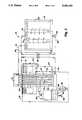
- FIG. 3is a more detailed diagrammatic view of the second-loop generator/first-loop absorber/first-loop condenser vessel illustrated in FIG. 2.
- refrigerantis not part of the present invention, so in the present description no particular refrigerant will be referred to.
- One of ordinary skill in the artis aware of refrigerant systems useful in the present apparatus.
- the same refrigerant system or different refrigerant systemsmay be used in the respective loops of the apparatus.
- This descriptionrefers generically to the components of a typical absorption refrigerant, which are a more volatile component or vapor (which, in liquid form, is sometimes referred to as a condensed vapor) and a less-volatile component. These components may coexist as a solution, they may be separated by applying heat to the solution and thus distilling the more volatile component away, and they may be re-combined to reconstitute the solution and reject heat. The vapor may also be condensed to reject heat or vaporized to accept heat. Refrigerants which operate in a different manner, but which may be used in comparable apparatus, are also contemplated for use herein.
- FIG. 1the heat and refrigerant transfers of a triple-effect refrigeration system are illustrated.
- the order of the componentshas been rearranged for clarity.
- the elements of FIG. 1are arranged in three columns.
- the left columnrelates to the first refrigeration loop; the center column shows the heat sources and the heat sink; and the right column shows the second refrigeration loop.
- the system 10is used to transfer heat from the heat load 12 to the heat sink 14. As is well known, this heat transfer can be carried out whether the heat load 12 is at a higher temperature than, a lower temperature than, or the same temperature as the heat sink 14.
- Heat from the load 12enters the first-loop evaporator 16 of the apparatus via the path 18. (All heat transfers to or from one of the refrigeration loops are represented in FIG. 1 by the letter Q next to an arrow indicating the direction of transfer.) Either the first-loop evaporator 16 is in direct heat-transfer contact with the heat load 12 or heat exchangers connect the first-loop evaporator 16 and the heat load 12 to accomplish this heat transfer.
- the heat entering the first-loop evaporator 16evaporates the condensed refrigerant vapor which has entered the first-loop evaporator 16 via the path 20.
- the effluent of the first-loop evaporator 16, which traverses the path 22,is refrigerant vapor which bears the heat from the heat load 12.
- the first-loop absorber 24receives the refrigerant vapor via the path 22 and contacts it with the less-volatile liquid refrigerant component received from the first-loop generator 26 via the paths 28.
- the resulting absorption of the refrigerant vapor into the less-volatile refrigerant liquidboth condenses the vapor, releasing its heat of vaporization, and releases heat of dissolution as the result of the absorption process.
- the resulting heatis rejected via the path 30 to the second-loop generator 32.
- the reconstituted composite refrigerantis passed via the paths 34 through the heat exchanger 35 to the first-loop generator 26.
- the heat exchanger 35preheats the composite refrigerant traversing the paths 34 before it enters the generator 26, using heat which otherwise would escape from the generator via the less-volatile refrigerant lines 28.
- the composite refrigerantis heated by the heater 36 sufficiently to distill away the more volatile refrigerant vapor, leaving the less volatile constituent of the refrigerant behind.
- the refrigerant vaporis delivered via the path 38 to the condenser 40.
- the less volatile constituent of the refrigerantgoes to the first-loop absorber 24 via path 28 (as previously described).
- the refrigerant vapor entering via the path 38is condensed.
- the heat of condensationis rejected from the first loop, and follows the path 42 to the second-loop generator 32.
- the condensed refrigerant vaporthen exits the first-loop condenser 40 via the path 20 and returns to the first-loop evaporator 16 to complete the first-loop cycle.
- a heat exchangeris also conventionally provided to transfer heat from the less-volatile refrigerant in the line 28 leaving the generator 26 to the composite refrigerant in the line 34 entering the generator 26.
- the organization of the second refrigerant loopis essentially identical to that of the first refrigerant loop.
- the primary differencesare in the heat inputs and outputs.
- the parts of the second loopare a second-loop evaporator 44, a second-loop absorber 46, a second-loop generator 32, and a second-loop condenser 50. These parts are connected in their operative relationship by a refrigerant vapor condensate line is 52, a refrigerant vapor line 54, composite refrigerant lines 56, less-volatile refrigerant, component lines 58, and a refrigerant vapor line 60.
- the heat inputs and outputs of the second loopare as follows.
- the heat required to operate the second-loop generator 32comes from the first-loop absorber 24 and condenser 40 via the paths 30 and 42, as previously described. Additional heat from the heat load 12 is received in the second-loop evaporator 44 via the path 48. Heat is rejected from the second-loop absorber 46 and condenser 50 via the paths 62 and 64. Although the paths 62 and 64 are shown as merging, it will be appreciated that separate heat sinks 14 can be provided for the second-loop absorber 46 and the condenser 50.
- the reconstituted composite refrigerantis passed via the paths 56 through the heat exchanger 65 to the second-loop generator 32. The heat exchanger 65 preheats the composite refrigerant traversing the paths 56 before it enters the generator 32, using heat which otherwise would escape from the generator 32 via the less-volatile refrigerant lines 58.
- FIGS. 2 and 3apparatus is disclosed which will function as illustrated in FIG. 1. Certain parts of FIGS. 2 and 3 correspond to those of FIG. 1, and thus share identical reference characters.
- the first-loop evaporator 16, the first-loop absorber 24, the first-loop condenser 40, the second-loop generator 32, and the second-loop condenser 50are all located in a single, subdivided first vessel 70.
- the first-loop generator 26is a separate vessel, and the second-loop evaporator 44 and the second-loop absorber 46 are each in a vessel 72.
- the first-loop generator 26has not been modified in this embodiment.
- the first vessel 70is made up of a lower cylindrical wall 74, a middle cylindrical wall 76, and an upper cylindrical wall 78.
- the first vessel defined by the space enclosed by the cylindrical walls 74, 76, and 78is subdivided by a lower bulkhead 80, a middle bulkhead 82, and an upper bulkhead 84 into a first header or entrance 86, a first-loop condenser (also known herein as a second chamber) 40, a first-loop absorber chamber (also known herein as a first chamber) 24, and a second header or exit 92 arranged in series.
- the bulkheads 80, 82, and 84are sealed to the cylindrical walls 74, 76, and 78 to close the first vessel and provide fluid-tight partitions.
- a multiplicity of substantially vertical tubes such as 94each having a cylindrical wall defining an interior surface 96 and an exterior surface 98, provides communication between the first header 86 and the second header 92.
- These tubes 94pass through the first-loop condenser (also known as a second chamber) 40 and the first-loop absorber (also known as a first chamber) 24.
- the bulkheads 80, 82, and 84also are welded, soldered, or otherwise sealed about the exterior surfaces 98 of the tubes 94 to maintain fluid-tight partitions between the first header 86, the first-loop condenser 40, the first-loop absorber 24, and the second header 92.
- the walls of the tubes 94taken together, define a partition between the first vessel 70 (which is outside the walls of the tubes 94 and between the bulkheads 80 and 84) and the second vessel (which is the sum of all the spaces within the walls of the tubes 94 in the vessel 70 between the bulkheads 80 and 84).
- the walls of the tubes 94serve as a heat transfer medium between the first and second vessels.
- the walls of the tubes 94are made of a copper alloy or another material which is structurally sound, not readily corroded, essentially liquid and vapor tight, and a good conductor of heat.
- first-loop condenser (second chamber) 40the space above the lower bulkhead 80, below the middle bulkhead 82, outside the tubes 94, and within the lower cylindrical wall 74.
- the spaces enclosed by the interior surfaces 96 of the tubes 94 and located within the confines of the first-loop condenser 40collectively define a first stage of the second-loop generator 32.
- the portions of the walls of the tubes 94 enclosed within the first-loop condenser 40define the heat transfer path 42 of FIG. 1.
- first-loop absorber or first chamber 24Above the middle bulkhead 82, below the upper bulkhead 84, outside the tubes 94, and within the middle cylindrical wall 76 is the first-loop absorber or first chamber 24.
- the spaces enclosed by the interior surfaces 96 of the tubes 94 within the confines of the first-loop absorber 24collectively define a second stage of the second-loop generator 32.
- the portions of the walls of the tubes 94 enclosed within the first-loop absorber 24define the heat transfer path 30 of FIG. 1.
- the first-loop condenser 40has an entrance generally indicated at 38 for receiving refrigerant vapor.
- the vaporcondenses on the exterior surfaces 98 of the tubes 94.
- the droplets of refrigerant condensate formed on the surfaces 98run down the tubes 94, due to the influence of gravity, forming a pool of the condensate in the sump 100 at the bottom of the first-loop condenser 40.
- the condensateis drained via the refrigerant path 20 to the first-loop evaporator 16. In this embodiment, the path 20 merges into the refrigerant recycle path 102.
- the heat of condensation from the is condensing refrigerant vapor in the first-loop condenser 40is mostly transferred to the tubes 94, and heats the contents of the tubes 94.
- the condenser 40thus provides its heat to the contents of the tubes 94.
- the first-loop evaporator 16preferably is an annular assembly located within the boundaries of the cylindrical wall 76 and surrounding the first-loop absorber 24.
- the condensed refrigerant vaporis delivered to the evaporator 16 from the sump 100 via the line 20 and the refrigerant recycle path 102.
- the condensateis sprayed through the sprayers 104 over an array of heat-exchange surfaces generally indicated at 106 which make up the first-loop evaporator 16.
- Water to be chilled (representing the heat load 12 of FIG. 1) or a separate heat exchange fluidis passed through the array 106 to transmit heat from the heat load 12 to the refrigerant vapor condensate.
- the heatthus accepted re-vaporizes the refrigerant condensate.
- the vapor produced in the first-loop evaporator 16fills the interior of the first-loop absorber 24, and is in contact with the surfaces 98 of the tubes 94 between the bulkheads 82 and 84.
- the low-volatility component of the refrigerantis delivered to the first-loop absorber 24 via the line 28.
- the low-volatility refrigerant componentis conveyed to the top surface of the distributor plate 108.
- the distributor plate 108deposits the low-volatility refrigerant component onto the exterior surfaces 98 of the tubes 94. Gravity causes sheets or drops of the less-volatile component of the refrigerant to flow down the exterior surfaces 98.
- the heat already in the low-volatility refrigerant component(which has just been boiled in the first-loop generator 26 to release the volatile component) is transferred to the tubes 94, and thus to their contents.
- the refrigerant vapor generated by the first-loop evaporator 16is absorbed by the less-volatile refrigerant component flowing down the tubes 94, reforming the original composite refrigerant and releasing a substantial quantity of heat of absorption and condensation. This heat is taken up by the tubes 94, and thus their contents.
- the newly-reconstituted composite refrigerantflows down the tubes 94 to the middle bulkhead 82 and collects in the inner sump 110.
- the contents of the inner sump 110are drained by the line 34 and returned to the first-loop generator 26.
- the first-loop evaporator 16also has an outer sump 112 in which the liquid sprayed onto the array of heat-exchange surfaces 106 of the first-stage evaporator 16, and which fails to evaporate, collects.
- the liquid refrigerant in the outer sump 112is recycled via the refrigerant recycle path 102 to the sprayers 104.
- the composite liquid second-loop refrigerant(which may be the same as or different from the first-loop refrigerant) enters the first header 86 of the second-loop generator 32 via the line 56.
- the composite refrigerant leaving the second-loop absorber 46is pumped by the pump 114 (FIG. 2) into the first header 86 and up into the entrances of the tubes 94.
- Heatis transferred to the composite second-loop refrigerant disposed within the interior surfaces 96 of the tubes 94 from the first-loop refrigerant vapor condensing on the is exterior surfaces 98 of the same tubes 94. Due to a combination of convection and the buoyancy of the refrigerant vapor bubbles formed in the tubes 94, the charge of second-loop composite refrigerant is driven upward within the tubes 94. The vapor bubbles rise particularly rapidly within the tubes 94.
- Absorptionis taking place on the exterior surfaces 98 of the tubes 94 within the first-stage absorber 24, which encloses the second stage of the second-loop generator 32.
- the second-loop refrigerant within the interior surfaces 96 of the tubes 94is further heated by the first-loop absorption taking place adjacent to the exterior surfaces 98 of the same tubes. This heating distills more refrigerant vapor from the less-volatile constituent of the second-loop refrigerant within the tubes 94.
- the rising bubbles of vapor formed within the interior surfaces 96expel both themselves and the entrained less-volatile liquid refrigerant through the tops 116 of the tubes 94 and into the second header 92.
- the vapor component of the second-loop refrigerant leaving the tubes 94is captured by the headspace in the second header 92.
- the less-volatile liquid constituent of the second-loop refrigerant expelled from the same tubes 94is deflected to and collects in a sump 118 defined by the top of the upper bulkhead 84. From the sump 118, the less-volatile second-loop refrigerant component is conveyed by the line 58 to the second-loop absorber 46.
- the second-loop condenser 50is also located within the second header 92.
- the second-loop condenser 50throws off heat to the heat sink 14 (FIG. 1), then collects the condensed second-loop refrigerant vapor for transport to the second-loop evaporator 44 via the line 52.
- the tubes 94in aggregate, have a large wall area, providing a high degree of heat exchange between the interior surfaces 96 and exterior surfaces 98 of the tubes 94. Direct heat exchange thus occurs between the first-loop condenser 40 and the second-loop generator 32, as well as between the first-loop absorber 24 and the second-loop generator 32. This provides much more efficient heat exchange than is found when heat is transferred indirectly via a coupling loop with an intermediate fluid, as has been suggested in earlier systems.
- the condenser space in this apparatusis outside the tubes 94, as has been the case in prior systems, but unlike prior systems, the second-loop generator space is inside those tubes.
- the absorbing processtakes place on the exterior surfaces 98 of the tubes 94, while the second-loop generator 32 is located within the very same tubes 94.
- the walls of the tubes 94are all that separates the absorber 24 and the generator 32 .
- This arrangementeliminates the need for a separate heat exchange loop in which a separate heat-exchange fluid is circulated between two heat exchangers, the walls of which respectively define second and third heat-exchange media in the second-loop generator 32 and the first-loop absorber 24.
- the present systemthus provides a direct heat-exchange relation (i.e. a single heat exchange medium) between the first-loop absorber 24 and the second-loop generator 32, and between the first-loop condenser 40 and the second-loop generator 32.
- a direct heat-exchange relationi.e. a single heat exchange medium
- Another distinctive feature of the present apparatusis the flow of the less volatile refrigerant for absorption along the outsides of the tubes 94, which are substantially straight and normally vertical ("normally” referring to the orientation of the apparatus in use).
- the refrigerantflows down the exterior surfaces 98 of the tubes 94 in a very thin, large surface area sheet which provides a large contact area between the less-volatile liquid phase and the vapor phase of the refrigerant.
- These tubescan have external and/or internal enhancements to provide for greater heat exchange surface area at relatively low cost.
- the vessel 72 containing the second-loop evaporator 44 and the second-loop absorber 46is somewhat similar to the corresponding apparatus of the first loop.
- the second-loop evaporator 44can be annular and can contain the second-loop absorber 46 within it so the refrigerant vapor from the second-loop evaporator 44 is released within the second-loop absorber 46.
- the illustrated apparatusshows a conventional second-loop absorber 46 with sprayers to subdivide the less volatile liquid refrigerant component.
- first-loop absorber 24 and second-loop generator 32could be provided in a different vessel than the combined first-loop condenser 40 and second-loop generator 32.
- first loop absorber and first loop condensercould be vertically interchanged and the second loop generator left unchanged.
Landscapes
- Engineering & Computer Science (AREA)
- Physics & Mathematics (AREA)
- Mechanical Engineering (AREA)
- Thermal Sciences (AREA)
- General Engineering & Computer Science (AREA)
- Sorption Type Refrigeration Machines (AREA)
- Engine Equipment That Uses Special Cycles (AREA)
Abstract
Description
Claims (26)
Priority Applications (9)
| Application Number | Priority Date | Filing Date | Title |
|---|---|---|---|
| US07945021US5284029B1 (en) | 1992-09-15 | 1992-09-15 | Triple effect absorption heat exchanger combining second cycle generator and first cycle absorber |
| PCT/US1993/008439WO1994007093A1 (en) | 1992-09-15 | 1993-09-09 | Triple effect absorption heat exchanger combining second cycle generator and first cycle absorber |
| DE69315700TDE69315700T2 (en) | 1992-09-15 | 1993-09-09 | Absorption heat pump with direct heat exchange between the expeller of a second circuit and the absorber and condenser of a first circuit |
| AT93921416TATE161086T1 (en) | 1992-09-15 | 1993-09-09 | ABSORPTION HEAT PUMP WITH DIRECT HEAT EXCHANGE BETWEEN THE EXPELLER OF A SECOND CIRCUIT AND THE ABSORBER AND CAPACITOR OF A FIRST CIRCUIT |
| JP50814094AJP3193720B2 (en) | 1992-09-15 | 1993-09-09 | Triple effect absorption heat exchanger combining a second cycle generator and a first cycle absorber |
| CA002144653ACA2144653C (en) | 1992-09-15 | 1993-09-09 | Triple effect absorption heat exchanger combining second cycle generator and first cycle absorber |
| EP93921416AEP0659258B1 (en) | 1992-09-15 | 1993-09-09 | Absorption heat pump with direct heat exchange between a second cycle generator and a first cycle absorber and condenser |
| KR1019950700833AKR100368180B1 (en) | 1992-09-15 | 1993-09-09 | Triple-effect absorption heat exchanger combining the second cycle generator and the first cycle absorber |
| CN93117834ACN1100241C (en) | 1992-09-15 | 1993-09-15 | Triple effect absorption heat exchahger combining second cycle generator and first cycle absorber |
Applications Claiming Priority (1)
| Application Number | Priority Date | Filing Date | Title |
|---|---|---|---|
| US07945021US5284029B1 (en) | 1992-09-15 | 1992-09-15 | Triple effect absorption heat exchanger combining second cycle generator and first cycle absorber |
Publications (2)
| Publication Number | Publication Date |
|---|---|
| US5284029Atrue US5284029A (en) | 1994-02-08 |
| US5284029B1 US5284029B1 (en) | 1996-05-14 |
Family
ID=25482489
Family Applications (1)
| Application Number | Title | Priority Date | Filing Date |
|---|---|---|---|
| US07945021Expired - LifetimeUS5284029B1 (en) | 1992-09-15 | 1992-09-15 | Triple effect absorption heat exchanger combining second cycle generator and first cycle absorber |
Country Status (9)
| Country | Link |
|---|---|
| US (1) | US5284029B1 (en) |
| EP (1) | EP0659258B1 (en) |
| JP (1) | JP3193720B2 (en) |
| KR (1) | KR100368180B1 (en) |
| CN (1) | CN1100241C (en) |
| AT (1) | ATE161086T1 (en) |
| CA (1) | CA2144653C (en) |
| DE (1) | DE69315700T2 (en) |
| WO (1) | WO1994007093A1 (en) |
Cited By (31)
| Publication number | Priority date | Publication date | Assignee | Title |
|---|---|---|---|---|
| US5390509A (en)* | 1991-11-27 | 1995-02-21 | Rocky Research | Triple effect absorption cycle apparatus |
| US5572884A (en)* | 1994-11-04 | 1996-11-12 | The Ohio State University Research Foundation | Heat pump |
| US5653117A (en)* | 1996-04-15 | 1997-08-05 | Gas Research Institute | Absorption refrigeration compositions containing thiocyanate, and absorption refrigeration apparatus |
| US5727397A (en)* | 1996-11-04 | 1998-03-17 | York International Corporation | Triple effect absorption refrigeration system |
| WO1998023906A1 (en)* | 1996-11-29 | 1998-06-04 | Gaz De France | Heating and cooling pump |
| US5783104A (en)* | 1996-04-16 | 1998-07-21 | Gas Research Institute | Absorption refrigeration compositions having germanium based compounds |
| USRE36045E (en)* | 1991-11-27 | 1999-01-19 | Rocky Research | Triple effect absorption cycle apparatus |
| US5899092A (en)* | 1996-10-10 | 1999-05-04 | Gaz De France | Chiller |
| US5911746A (en)* | 1997-12-24 | 1999-06-15 | Gas Research Institute | Gax absorption cycle with secondary refrigerant |
| US5941094A (en)* | 1998-05-18 | 1999-08-24 | York International Corporation | Triple-effect absorption refrigeration system having a combustion chamber cooled with a sub-ambient pressure solution stream |
| US6003331A (en)* | 1998-03-02 | 1999-12-21 | York International Corporation | Recovery of flue gas energy in a triple-effect absorption refrigeration system |
| US6122930A (en)* | 1998-03-19 | 2000-09-26 | Hitachi, Ltd. | Absorption refrigerating machine |
| US20020056163A1 (en)* | 1997-04-29 | 2002-05-16 | Estes Kurt A. | Non aqueous washing apparatus and method |
| US20030167790A1 (en)* | 2001-04-27 | 2003-09-11 | Hideaki Koike | Ammonia absorption type water chilling/heating device |
| US6658851B2 (en)* | 2000-10-18 | 2003-12-09 | Solutherm B.V. | Apparatus for subliming or condensing a water-containing fluid in a closed space |
| US20040117919A1 (en)* | 1997-04-29 | 2004-06-24 | Conrad Daniel C. | Non-aqueous washing machine & methods |
| US20050092352A1 (en)* | 2003-10-31 | 2005-05-05 | Luckman Joel A. | Non-aqueous washing apparatus and method |
| US20050096242A1 (en)* | 2003-10-31 | 2005-05-05 | Luckman Joel A. | Method for laundering fabric with a non-aqueous working fluid using a select rinse fluid |
| US20050092033A1 (en)* | 2003-10-31 | 2005-05-05 | Luckman Joel A. | Fabric laundering apparatus adapted for using a select rinse fluid |
| US20050096243A1 (en)* | 2003-10-31 | 2005-05-05 | Luckman Joel A. | Fabric laundering using a select rinse fluid and wash fluids |
| US20050091756A1 (en)* | 2003-10-31 | 2005-05-05 | Tremitchell Wright | Non-aqueous washing machine & methods |
| US20050150059A1 (en)* | 2003-10-31 | 2005-07-14 | Luckman Joel A. | Non-aqueous washing apparatus and method |
| US20050222002A1 (en)* | 2003-10-31 | 2005-10-06 | Luckman Joel A | Method for a semi-aqueous wash process |
| US20050224099A1 (en)* | 2004-04-13 | 2005-10-13 | Luckman Joel A | Method and apparatus for cleaning objects in an automatic cleaning appliance using an oxidizing agent |
| US20050263173A1 (en)* | 2003-10-31 | 2005-12-01 | Luckman Joel A | Method for fluid recovery in a semi-aqueous wash process |
| US20060260065A1 (en)* | 2005-05-23 | 2006-11-23 | Wright Tremitchell L | Methods and apparatus to accelerate the drying of aqueous working fluids |
| US7300468B2 (en) | 2003-10-31 | 2007-11-27 | Whirlpool Patents Company | Multifunctioning method utilizing a two phase non-aqueous extraction process |
| US20080104960A1 (en)* | 2006-11-07 | 2008-05-08 | H2Gen Innovations, Inc. | Heat exchanger having a counterflow evaporator |
| US7513132B2 (en) | 2003-10-31 | 2009-04-07 | Whirlpool Corporation | Non-aqueous washing machine with modular construction |
| US7837741B2 (en) | 2004-04-29 | 2010-11-23 | Whirlpool Corporation | Dry cleaning method |
| CN101984308A (en)* | 2009-11-11 | 2011-03-09 | 李华玉 | Two-stage first kind absorption heat pump taking triple effect as first stage |
Families Citing this family (2)
| Publication number | Priority date | Publication date | Assignee | Title |
|---|---|---|---|---|
| CN101280981B (en)* | 2008-05-08 | 2010-10-06 | 深圳职业技术学院 | Diffusion absorption type refrigeration system |
| CN113668538A (en)* | 2021-07-20 | 2021-11-19 | 中铁建华南建设有限公司 | Fluid material conveying device |
Citations (10)
| Publication number | Priority date | Publication date | Assignee | Title |
|---|---|---|---|---|
| US2196911A (en)* | 1935-10-28 | 1940-04-09 | Servel Inc | System for heating and refrigeration |
| US2729952A (en)* | 1952-07-11 | 1956-01-10 | Servel Inc | Absorption refrigeration apparatus |
| US3323323A (en)* | 1965-10-22 | 1967-06-06 | Whirlpool Co | Absorption generator |
| US3483710A (en)* | 1968-06-13 | 1969-12-16 | Crane Co | Cascade absorption refrigeration system |
| US4018583A (en)* | 1975-07-28 | 1977-04-19 | Carrier Corporation | Refrigeration heat recovery system |
| US4531374A (en)* | 1981-03-24 | 1985-07-30 | Georg Alefeld | Multi-stage apparatus having working-fluid and absorption cycles, and method of operation thereof |
| US4542628A (en)* | 1984-11-13 | 1985-09-24 | The United States Of America As Represented By The United States Department Of Energy | Coupled dual loop absorption heat pump |
| US4545217A (en)* | 1983-11-09 | 1985-10-08 | Mitsubishi Denki Kabushiki Kaisha | Steam generating and condensing apparatus |
| US4732008A (en)* | 1986-11-24 | 1988-03-22 | The United States Of America As Represented By The United States Department Of Energy | Triple effect absorption chiller utilizing two refrigeration circuits |
| US5097676A (en)* | 1990-10-24 | 1992-03-24 | Erickson Donald C | Vapor exchange duplex GAX absorption cycle |
Family Cites Families (4)
| Publication number | Priority date | Publication date | Assignee | Title |
|---|---|---|---|---|
| DE674460C (en)* | 1937-01-20 | 1939-04-14 | Rheinmetall Borsig Akt Ges | Device for expelling the refrigerant from continuously operating absorption refrigeration machines |
| US3990263A (en)* | 1974-03-18 | 1976-11-09 | Emmanuil Gershkovich Ainbinder | Absorption refrigerating installation |
| US4477396A (en)* | 1980-08-13 | 1984-10-16 | Battelle Development Corp. | Countercurrent flow absorber and desorber |
| US4921515A (en)* | 1988-10-20 | 1990-05-01 | Kim Dao | Advanced regenerative absorption refrigeration cycles |
- 1992
- 1992-09-15USUS07945021patent/US5284029B1/ennot_activeExpired - Lifetime
- 1993
- 1993-09-09EPEP93921416Apatent/EP0659258B1/ennot_activeExpired - Lifetime
- 1993-09-09DEDE69315700Tpatent/DE69315700T2/ennot_activeExpired - Fee Related
- 1993-09-09ATAT93921416Tpatent/ATE161086T1/enactive
- 1993-09-09CACA002144653Apatent/CA2144653C/ennot_activeExpired - Lifetime
- 1993-09-09KRKR1019950700833Apatent/KR100368180B1/ennot_activeExpired - Lifetime
- 1993-09-09JPJP50814094Apatent/JP3193720B2/ennot_activeExpired - Lifetime
- 1993-09-09WOPCT/US1993/008439patent/WO1994007093A1/enactiveIP Right Grant
- 1993-09-15CNCN93117834Apatent/CN1100241C/ennot_activeExpired - Lifetime
Patent Citations (10)
| Publication number | Priority date | Publication date | Assignee | Title |
|---|---|---|---|---|
| US2196911A (en)* | 1935-10-28 | 1940-04-09 | Servel Inc | System for heating and refrigeration |
| US2729952A (en)* | 1952-07-11 | 1956-01-10 | Servel Inc | Absorption refrigeration apparatus |
| US3323323A (en)* | 1965-10-22 | 1967-06-06 | Whirlpool Co | Absorption generator |
| US3483710A (en)* | 1968-06-13 | 1969-12-16 | Crane Co | Cascade absorption refrigeration system |
| US4018583A (en)* | 1975-07-28 | 1977-04-19 | Carrier Corporation | Refrigeration heat recovery system |
| US4531374A (en)* | 1981-03-24 | 1985-07-30 | Georg Alefeld | Multi-stage apparatus having working-fluid and absorption cycles, and method of operation thereof |
| US4545217A (en)* | 1983-11-09 | 1985-10-08 | Mitsubishi Denki Kabushiki Kaisha | Steam generating and condensing apparatus |
| US4542628A (en)* | 1984-11-13 | 1985-09-24 | The United States Of America As Represented By The United States Department Of Energy | Coupled dual loop absorption heat pump |
| US4732008A (en)* | 1986-11-24 | 1988-03-22 | The United States Of America As Represented By The United States Department Of Energy | Triple effect absorption chiller utilizing two refrigeration circuits |
| US5097676A (en)* | 1990-10-24 | 1992-03-24 | Erickson Donald C | Vapor exchange duplex GAX absorption cycle |
Non-Patent Citations (2)
| Title |
|---|
| Evaluation of a Commercial Advanced Absorption Heat Pump Breadboard, Proceedings of the 2nd DOE/ORNL heat pump conference (CONF 8804100), Modahl & Hayes, p. 117.* |
| Evaluation of a Commercial Advanced Absorption Heat Pump Breadboard, Proceedings of the 2nd DOE/ORNL heat pump conference (CONF-8804100), Modahl & Hayes, p. 117. |
Cited By (44)
| Publication number | Priority date | Publication date | Assignee | Title |
|---|---|---|---|---|
| USRE36045E (en)* | 1991-11-27 | 1999-01-19 | Rocky Research | Triple effect absorption cycle apparatus |
| US5390509A (en)* | 1991-11-27 | 1995-02-21 | Rocky Research | Triple effect absorption cycle apparatus |
| US5572884A (en)* | 1994-11-04 | 1996-11-12 | The Ohio State University Research Foundation | Heat pump |
| US5653117A (en)* | 1996-04-15 | 1997-08-05 | Gas Research Institute | Absorption refrigeration compositions containing thiocyanate, and absorption refrigeration apparatus |
| US5783104A (en)* | 1996-04-16 | 1998-07-21 | Gas Research Institute | Absorption refrigeration compositions having germanium based compounds |
| US5899092A (en)* | 1996-10-10 | 1999-05-04 | Gaz De France | Chiller |
| US5727397A (en)* | 1996-11-04 | 1998-03-17 | York International Corporation | Triple effect absorption refrigeration system |
| WO1998023906A1 (en)* | 1996-11-29 | 1998-06-04 | Gaz De France | Heating and cooling pump |
| FR2756621A1 (en)* | 1996-11-29 | 1998-06-05 | Gaz De France | THERMO-FRIGOPOMPE |
| US8262741B2 (en) | 1997-04-29 | 2012-09-11 | Whirlpool Corporation | Non-aqueous washing apparatus and method |
| US20020056163A1 (en)* | 1997-04-29 | 2002-05-16 | Estes Kurt A. | Non aqueous washing apparatus and method |
| US20080189872A9 (en)* | 1997-04-29 | 2008-08-14 | Wright Tremitchell L | Non-aqueous washing apparatus and method |
| US7534304B2 (en) | 1997-04-29 | 2009-05-19 | Whirlpool Corporation | Non-aqueous washing machine and methods |
| US20040117919A1 (en)* | 1997-04-29 | 2004-06-24 | Conrad Daniel C. | Non-aqueous washing machine & methods |
| US20050071928A1 (en)* | 1997-04-29 | 2005-04-07 | Wright Tremitchell L. | Non-aqueous washing apparatus and method |
| US5911746A (en)* | 1997-12-24 | 1999-06-15 | Gas Research Institute | Gax absorption cycle with secondary refrigerant |
| US6003331A (en)* | 1998-03-02 | 1999-12-21 | York International Corporation | Recovery of flue gas energy in a triple-effect absorption refrigeration system |
| US6122930A (en)* | 1998-03-19 | 2000-09-26 | Hitachi, Ltd. | Absorption refrigerating machine |
| US6233968B1 (en) | 1998-03-19 | 2001-05-22 | Hitachi, Ltd. | Absorption refrigerating machine |
| US5941094A (en)* | 1998-05-18 | 1999-08-24 | York International Corporation | Triple-effect absorption refrigeration system having a combustion chamber cooled with a sub-ambient pressure solution stream |
| US6658851B2 (en)* | 2000-10-18 | 2003-12-09 | Solutherm B.V. | Apparatus for subliming or condensing a water-containing fluid in a closed space |
| US20030167790A1 (en)* | 2001-04-27 | 2003-09-11 | Hideaki Koike | Ammonia absorption type water chilling/heating device |
| US20050096243A1 (en)* | 2003-10-31 | 2005-05-05 | Luckman Joel A. | Fabric laundering using a select rinse fluid and wash fluids |
| US7513004B2 (en) | 2003-10-31 | 2009-04-07 | Whirlpool Corporation | Method for fluid recovery in a semi-aqueous wash process |
| US20050091755A1 (en)* | 2003-10-31 | 2005-05-05 | Conrad Daniel C. | Non-aqueous washing machine & methods |
| US20050150059A1 (en)* | 2003-10-31 | 2005-07-14 | Luckman Joel A. | Non-aqueous washing apparatus and method |
| US20050222002A1 (en)* | 2003-10-31 | 2005-10-06 | Luckman Joel A | Method for a semi-aqueous wash process |
| US20050092352A1 (en)* | 2003-10-31 | 2005-05-05 | Luckman Joel A. | Non-aqueous washing apparatus and method |
| US20050263173A1 (en)* | 2003-10-31 | 2005-12-01 | Luckman Joel A | Method for fluid recovery in a semi-aqueous wash process |
| US7739891B2 (en) | 2003-10-31 | 2010-06-22 | Whirlpool Corporation | Fabric laundering apparatus adapted for using a select rinse fluid |
| US7300468B2 (en) | 2003-10-31 | 2007-11-27 | Whirlpool Patents Company | Multifunctioning method utilizing a two phase non-aqueous extraction process |
| US7695524B2 (en) | 2003-10-31 | 2010-04-13 | Whirlpool Corporation | Non-aqueous washing machine and methods |
| US20050092033A1 (en)* | 2003-10-31 | 2005-05-05 | Luckman Joel A. | Fabric laundering apparatus adapted for using a select rinse fluid |
| US20050091756A1 (en)* | 2003-10-31 | 2005-05-05 | Tremitchell Wright | Non-aqueous washing machine & methods |
| US7513132B2 (en) | 2003-10-31 | 2009-04-07 | Whirlpool Corporation | Non-aqueous washing machine with modular construction |
| US20050096242A1 (en)* | 2003-10-31 | 2005-05-05 | Luckman Joel A. | Method for laundering fabric with a non-aqueous working fluid using a select rinse fluid |
| US20050224099A1 (en)* | 2004-04-13 | 2005-10-13 | Luckman Joel A | Method and apparatus for cleaning objects in an automatic cleaning appliance using an oxidizing agent |
| US7837741B2 (en) | 2004-04-29 | 2010-11-23 | Whirlpool Corporation | Dry cleaning method |
| US20060260065A1 (en)* | 2005-05-23 | 2006-11-23 | Wright Tremitchell L | Methods and apparatus to accelerate the drying of aqueous working fluids |
| US7966684B2 (en) | 2005-05-23 | 2011-06-28 | Whirlpool Corporation | Methods and apparatus to accelerate the drying of aqueous working fluids |
| US20080104960A1 (en)* | 2006-11-07 | 2008-05-08 | H2Gen Innovations, Inc. | Heat exchanger having a counterflow evaporator |
| US7882809B2 (en)* | 2006-11-07 | 2011-02-08 | L'air Liquide, Societe Anonyme Pour L'etude Et L'exploitation Des Procedes Georges Claude | Heat exchanger having a counterflow evaporator |
| CN101984308A (en)* | 2009-11-11 | 2011-03-09 | 李华玉 | Two-stage first kind absorption heat pump taking triple effect as first stage |
| CN101984308B (en)* | 2009-11-11 | 2012-10-31 | 李华玉 | Two-stage first-class absorption heat pump with three-effect as the first stage |
Also Published As
| Publication number | Publication date |
|---|---|
| JPH08501382A (en) | 1996-02-13 |
| DE69315700D1 (en) | 1998-01-22 |
| EP0659258B1 (en) | 1997-12-10 |
| DE69315700T2 (en) | 1998-07-16 |
| WO1994007093A1 (en) | 1994-03-31 |
| ATE161086T1 (en) | 1997-12-15 |
| CN1100241C (en) | 2003-01-29 |
| CN1086006A (en) | 1994-04-27 |
| CA2144653A1 (en) | 1994-03-31 |
| KR100368180B1 (en) | 2003-03-26 |
| KR950703136A (en) | 1995-08-23 |
| US5284029B1 (en) | 1996-05-14 |
| EP0659258A1 (en) | 1995-06-28 |
| JP3193720B2 (en) | 2001-07-30 |
| CA2144653C (en) | 2004-11-16 |
Similar Documents
| Publication | Publication Date | Title |
|---|---|---|
| US5284029A (en) | Triple effect absorption heat exchanger combining second cycle generator and first cycle absorber | |
| US3831397A (en) | Multi-stage absorption refrigeration system | |
| US5426955A (en) | Absorption refrigeration system with additive separation method | |
| US4338268A (en) | Open cycle thermal boosting system | |
| JPS5913670B2 (en) | Dual effect absorption refrigeration equipment | |
| US3124938A (en) | absorption refrigeration systems and method of operation | |
| US5467614A (en) | Dual-circuit, multiple-effect refrigeration system and method | |
| US3390544A (en) | Absorption refrigeration systems having solution-cooled absorbers | |
| US5048308A (en) | Absorption refrigerator | |
| US3396549A (en) | Multiple-effect absorption refrigeration systems | |
| US2167663A (en) | Refrigeration | |
| US3389574A (en) | Multiple-effect absorption refrigeration systems with refrigerant economizers | |
| US3452550A (en) | Maintaining effectiveness of additives in absorption refrigeration systems | |
| US3389573A (en) | Refrigerant condensate circuit in multiple-effect absorption refrigeration systems | |
| US5600968A (en) | Absorption machine with multi-temperature compartments | |
| US3389572A (en) | Multiple-effect absorption refrigeration systems | |
| US1846006A (en) | Refrigeration | |
| US3389570A (en) | Refrigerant condensate circuit in multiple-effect absorption refrigeration systems | |
| US3514970A (en) | Absorption refrigeration machine | |
| JPS60162166A (en) | Multiple effect absorption type refrigerator | |
| JP3125063B2 (en) | Multi-effect distillation device | |
| GB2314149A (en) | Thermosyphon refrigeration apparatus | |
| JP3489934B2 (en) | Evaporator in absorption refrigerator | |
| AU699349B2 (en) | Process and apparatus for vapor pressure enhancement | |
| JP3236721B2 (en) | Regenerator for absorption refrigerator |
Legal Events
| Date | Code | Title | Description |
|---|---|---|---|
| AS | Assignment | Owner name:GAS RESEARCH INSTITUTE, ILLINOIS Free format text:ASSIGNMENT OF ASSIGNORS INTEREST.;ASSIGNORS:KEUPER, EDWARD F.;PLZAK, WILLIAM J.;REEL/FRAME:006339/0785 Effective date:19920915 | |
| STCF | Information on status: patent grant | Free format text:PATENTED CASE | |
| RR | Request for reexamination filed | Effective date:19940525 | |
| B1 | Reexamination certificate first reexamination | ||
| FEPP | Fee payment procedure | Free format text:PAYOR NUMBER ASSIGNED (ORIGINAL EVENT CODE: ASPN); ENTITY STATUS OF PATENT OWNER: LARGE ENTITY | |
| FPAY | Fee payment | Year of fee payment:4 | |
| AS | Assignment | Owner name:AMERICAN STANDARD INTERNATIONAL INC., NEW YORK Free format text:NOTICE OF ASSIGNMENT;ASSIGNOR:AMERICAN STANDARD INC., A CORPORATION OF DELAWARE;REEL/FRAME:011474/0650 Effective date:20010104 | |
| FPAY | Fee payment | Year of fee payment:8 | |
| FPAY | Fee payment | Year of fee payment:12 | |
| AS | Assignment | Owner name:GAS TECHNOLOGY INSTITUTE, ILLINOIS Free format text:ASSIGNMENT OF ASSIGNORS INTEREST;ASSIGNOR:GAS RESEARCH INSTITUTE;REEL/FRAME:017448/0282 Effective date:20060105 |