US5283682A - Reactionless scanning and positioning system - Google Patents
Reactionless scanning and positioning systemDownload PDFInfo
- Publication number
- US5283682A US5283682AUS07/957,420US95742092AUS5283682AUS 5283682 AUS5283682 AUS 5283682AUS 95742092 AUS95742092 AUS 95742092AUS 5283682 AUS5283682 AUS 5283682A
- Authority
- US
- United States
- Prior art keywords
- reaction mass
- mirror carrier
- pivotal movement
- mirror
- axis
- Prior art date
- Legal status (The legal status is an assumption and is not a legal conclusion. Google has not performed a legal analysis and makes no representation as to the accuracy of the status listed.)
- Expired - Lifetime
Links
- 238000006243chemical reactionMethods0.000claimsabstractdescription118
- 230000000694effectsEffects0.000claimsdescription9
- 238000000034methodMethods0.000claims6
- 239000002184metalSubstances0.000claims1
- 238000010168coupling processMethods0.000description15
- 238000005859coupling reactionMethods0.000description13
- 230000008878couplingEffects0.000description12
- 230000010355oscillationEffects0.000description3
- 238000005259measurementMethods0.000description2
- 230000007246mechanismEffects0.000description2
- 230000003534oscillatory effectEffects0.000description2
- 230000009467reductionEffects0.000description2
- 239000011800void materialSubstances0.000description2
- 230000004075alterationEffects0.000description1
- 238000006073displacement reactionMethods0.000description1
- 238000005516engineering processMethods0.000description1
- 238000012986modificationMethods0.000description1
- 230000004048modificationEffects0.000description1
- 230000003287optical effectEffects0.000description1
Images


Classifications
- G—PHYSICS
- G02—OPTICS
- G02B—OPTICAL ELEMENTS, SYSTEMS OR APPARATUS
- G02B7/00—Mountings, adjusting means, or light-tight connections, for optical elements
- G02B7/18—Mountings, adjusting means, or light-tight connections, for optical elements for prisms; for mirrors
- G02B7/182—Mountings, adjusting means, or light-tight connections, for optical elements for prisms; for mirrors for mirrors
- G02B7/1821—Mountings, adjusting means, or light-tight connections, for optical elements for prisms; for mirrors for mirrors for rotating or oscillating mirrors
Definitions
- This inventionrelates generally to scanning systems and, more specifically, to a thermal infrared radiometer scanning system comprising a movable mirror, a reaction mass, and an associated mirror position sensing system.
- Scanning systemstypically use a mirror, lens, or detector, or the like, to scan a target area.
- the above problemsare solved and a technical advance is achieved in the field by the reactionless scanning and positioning system of the present invention.
- the system of the present inventionincludes a mirror scanning assembly (including a mirror support) coupled to a reaction mass having a rotational moment of inertia equal and opposite to that of the mirror assembly, so that the system is effectively reactionless.
- the spacecraft containing the scanning systemis thus not caused to shake or required to compensate for disturbances generated during a scanning operation.
- the overall mechanical design of the scanning systemis optimized to require minimum power consumption by the actuators used to drive the scanning assembly.
- This minimum power consumptionis effected by having the mirror assembly mounted on flexible pivots.
- the torsional stiffness of these flexible pivotsis chosen to provide a mechanically resonant frequency such that a minimum amount of power is required to angularly position the mirror.
- Stored spring-effect energy in the flexible pivotsis used to help return the mirror in a scanning direction opposite to the direction in which the mirror is initially moved by the mirror scanning actuators. Because of the system mechanical resonance, movement of the mirror in this opposite direction is thus accomplished by supplying a minimal amount of power to the mirror scanning actuators.
- the mirror---a coarse positioning modewherein the mirror is moved slowly over an arc of 200 degrees or more
- a relatively fast scanning modewherein the mirror is moved rapidly back and forth over an arc of approximately ⁇ 2.5 degrees.
- a position encoder discis used in both modes to determine the position of the mirror.
- the position of the mirroris accurately determinable in a fast scanning mode due to the novel mounting of the mirror with respect to the mirror position sensing system.
- the flexible pivots used to support the mirrorimpart an eccentric motion to the axis of rotation of the mirror. This eccentric motion causes "wobbling" of the mirror.
- the present inventionemploys a mounting arrangement of the position encoder disc on its own flexible pivots as well as a unique connection between the position encoder disc and the mirror which collectively function to decouple the effect of the eccentric motion of the mirror rotational axis. This decoupling provides for an extremely accurate measurement of the mirror position.
- the mirror scanning operationis accomplished by using actuator motor cores which are not attached to any moving part of the mirror assembly in order to reduce the rotational inertia of the mirror assembly. This reduction of inertia allows the scanning system to scan at a faster rate.
- FIG. 1is a perspective view of the resonant optical scanning and position sensing system
- FIG. 2is a diagrammatic view showing operative components of the scanning system
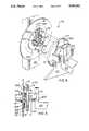
- FIG. 3is cut-away view illustrating the location of the flexible pivots used to attach the position encoder disc to the yoke;
- FIGS. 4 and 5illustrate the inverted box flexure used to attach the position encoder disc to the mirror carrier
- FIG. 6is a cut-away view of a typical flexible pivot
- FIG. 7illustrates the coarse positioning movement of the mirror and yoke with respect to the scanning system support structure
- FIG. 8illustrates one set of two drive flexures used to couple the reaction mass to the mirror carrier
- FIG. 9illustrates the relative movement between the reaction mass and the mirror carrier as a result of the operation of the drive flexures.
- FIG. 10illustrates the coupling of a typical linear actuator to the reaction mass and the yoke.
- FIG. 1is a perspective view showing operative components of the reactionless scanning and positioning system 100 (hereinafter referred to as "scanning system” 100).
- FIG. 2is a diagrammatic view of scanning system 100. The operation of scanning system 100 can be best understood by concurrent reference to both FIGS. 1 and 2.
- Scanning system 100is essentially a "three-mass system” wherein the three main components are (1) a mirror/mirror carrier assembly 101/103, (2) a reaction mass 105, and (3) a yoke 107.
- Yoke 107is coupled by a pair of flexible pivots 133, 233 to mirror/mirror carrier assembly 101/103.
- a yoke drive motor 111 attached to a fixed support 109is used for coarse positioning of the yoke/mirror/mirror carrier assembly 107/101/103 about axis 220.
- Yoke drive motor 111is connected via a gear 112 to drive shaft 210, which is, in turn, fixedly connected to outer shaft 205.
- Outer shaft 205is fixedly connected to yoke 107.
- An inner shaft (spindle) 207is located within outer shaft 205.
- rotation of gear 112 by yoke drive motor 111causes rotation of yoke 107 and a corresponding rotation of mirror/mirror carrier assembly 101/103 about axis 220.
- the coarse positioning adjustmentis independent of the scanning function and is used to rotate mirror/mirror carrier assembly 101/103 over a relatively large arc (200 degrees or more) for target location and for calibration purposes.
- Yoke 107is also coupled to reaction mass 105 by a pair of flexible pivots 231, 231'.
- two pairs of actuators 140(only one pair of which is visible in FIGS. 1 and 2) cause reaction mass 105 to oscillate about flexible pivots 231, 231' over a small angular excursion.
- This oscillation of reaction mass 105causes an opposite oscillation of mirror carrier 103 which is attached via a pair of drive flexures 117, 117' to reaction mass 105.
- Drive flexures 117, 117'function to cause the oscillation of mirror carrier 103 about flexible pivots 133, 233 in an angular direction opposite to that of reaction mass 105.
- Reaction mass 105has a rotational moment of inertia equal and opposite to that of the mirror/mirror carrier assembly 101/103, so that the system 101/103/105 is effectively reactionless when performing a scanning operation.
- a position encoder disc 113is located between yoke 107 and support 109.
- Position encoder disc 113rotates essentially in accordance with drive shaft 210, as well as with mirror/mirror carrier assembly 101/103.
- a pair of encoder read heads 115, 115'are fixedly attached to support 109 and are located proximate position encoder disc 113 in order to determine the mirror rotational position with respect to support 109.
- a novel coupling methodis employed between position encoder disc 113 and mirror carrier 103, as well as between position encoder disc 113 and drive shaft 210.
- Position encoder disc 113is rigidly connected to inner shaft (spindle) 207 which rotates via flexible pivots 235, 236 located at opposite ends of inner shaft 207. These flexible pivots 235, 236 connect inner shaft 207 to outer shaft 205, which in turn is connected to yoke 107.
- This coupling methodallows closer tracking of position encoder disc 11 with mirror rotational position by providing decoupling between position encoder disc 113 and the eccentric movement imparted to mirror carrier 103 by flexible pivots 133, 133' as mirror carrier is rotatably moved.
- yoke 107is rotatably attached to a fixed support 109, 109'.
- the entire mirror/mirror carrier and reaction mass assembly 101/103/105(which is movably connected to yoke 107) is also movably coupled to support 109, 109' via a right yoke support bearing pair 225 and a left yoke support bearing pair 223.
- Right yoke support shaft 116rotates on bearing pair 223 which is enclosed by bushing 118.
- Mirror/mirror carrier 101/103 and reaction mass 105are movably coupled to yoke 107 so that they move together as yoke 107 is rotated by yoke drive motor 111.
- Yoke drive motor 111 attached to support 109is used for coarse positioning of the yoke 107 over an arc of at least 200 degrees.
- FIG. 7illustrates the coarse positioning of mirror 101 and yoke 107 with respect to scanning system 100 support 109' (and support 109, which is not shown on FIG. 7).
- FIG. 7illustrates the movement of scanning system 100 yoke 107 and mirror 101 over a substantial angular displacement 700 between positions 701 and 703.
- Yoke 107 and mirror 101are also capable of movement in direction 705.
- Coarse positioning of mirror 101is performed in order to accomplish at least two functions. One of these functions is to move the mirror 101 to a desired position so that a mirror scanning operation can be performed. Another function of coarse positioning of mirror 101 is to move the mirror 101 to a position in front of a calibration source (not shown) so that a thermal infrared radiometer or other device (not shown) can be calibrated.
- the overall mechanical design of scanning system 100is optimized to require minimum power consumption by the actuators 140 used to drive the reaction mass/mirror carrier/mirror assembly 105/101/103.
- This minimum power consumptionis effected by flexibly coupling mirror/mirror carrier assembly 101/103 and reaction mass 105 to yoke 107.
- Mirror/mirror carrier assembly 101/103is coupled to yoke 107 via a pair of flexible pivots 133 and 233.
- Reaction mass 105is coupled to yoke 107 via another pair of flexible pivots 231 and 231'.
- a typical flexible pivot 600is shown in FIG. 6.
- Flexible pivots such as 600allow two rotatable members (not shown) to be coupled at ends 610, 620 with a torsional resistance between the two rotatable members about axis 604. This torsional resistance is imparted by spring members 601, 602, 603.
- the flexible pivot 600provides a frictionless coupling between the rotatable members.
- the torsional stiffness of flexible pivots 133 and 233 shown on FIGS. 1 and 2is chosen to provide a mechanically resonant frequency of the moving mass of the scanning system 100 at the desired scanning frequency such that the amount of power necessary to generate the desired resonant scanning is minimized.
- Spring-effect energy stored in flexible pivots 133 and 233is used to movably return mirror 101 during scanning in a direction opposite to the direction in which the mirror 105 is moved by actuators 140. In this manner, power necessary to control mirror 101 is minimized.
- reaction mass 105is coupled to mirror carrier 103 via a pair of drive flexures 117, 117'.
- Two pairs of actuators 140are coupled to reaction mass 105.
- One pairis located on the front of reaction mass 105 as shown in FIG. 1.
- the second pairis analogously located on the back of reaction mass 105 and is not shown.
- FIG. 8illustrates one (117) of the two drive flexure pairs used to couple reaction mass 105 to mirror carrier 103.
- FIG. 9illustrates the relative movement between reaction mass 105 and mirror carrier 103 as a result of the operation of each drive flexure 117 and 117'.
- drive flexure 117comprises two separate members, each of which includes a flat spring 801, 801'.
- Plate 803is used to attach flat spring 801 to reaction mass 105.
- Plate 805is used to attach flat spring 801 to mirror carrier 103.
- Plate 807is used to attach flat spring 801' to mirror carrier 103.
- Plate 809is used to attach flat spring 801' to reaction mass 105.
- Plate 803(which is attached to reaction mass 105) and the front end of reaction mass 105 are displaced in direction 900;
- Plate 809(which is attached to reaction mass 105) is displaced in a clockwise direction 901 about axis 240;
- FIG. 10illustrates the coupling of a typical linear actuator to reaction mass 105 and yoke 107.
- Each of these actuators 140comprises an actuator motor coil 127 and an actuator motor core 128.
- the motor coil 127 of each actuator 140is directly attached to yoke 107 by a coupling plate 1001.
- the motor core 128 of each actuator 140is attached to reaction mass 105.
- each actuator 140is energized to cause its motor core 128 to move either up or down in direction 1003. Movement in direction 1003 by actuator motor core 128 causes a corresponding movement of reaction mass 105.
- Each actuator 140is a linear-type actuator which is well-known in the art.
- a typical similar actuatoris manufactured by Ball Aerospace Corp., Post Office Box 1062, Boulder, Colo. 80306.
- the rotational inertia of the reaction mass/mirror/mirror carrier assembly 105/101/103is reduced. This reduction of inertia allows scanning system 100 to scan at a faster rate.
- actuators 140 and 140'Only the front pair of actuators, specifically left and right actuators 140 and 140' are shown in FIG. 1. An identical pair of actuators are similarly positioned in an analogous position at the rear of reaction mass 105. Actuators 140 and 140' are used to impart an oscillatory motion to reaction mass 105. This oscillatory motion of reaction mass 105 causes mirror/mirror carrier 101/103 to oscillate and thereby scan a target object. The angular excursion of the mirror about axis 220 during a typical scanning operation is a total of approximately 5 degrees.
- Mirror/mirror carrier assembly 101/103is coupled to reaction mass 105 by a pair of drive flexures 117, 117'.
- Reaction mass 105has a rotational moment of inertia equal and opposite to that of the mirror/mirror carrier assembly 101/103, so that the system 101/103/105 is effectively reactionless.
- the spacecraft containing the scanning system 10is thus not caused to shake or required to compensate for disturbances generated during a scanning operation.
- position encoder disc 113is located between the left end of yoke 107 and support 109, as shown in FIGS. 1, 2 and 3. Position encoder disc 113 rotates indirectly in accordance with the rotation of drive shaft 210, as well as with the rotation of mirror/mirror carrier assembly 101/103. Position encoding devices such as position encoder disc 113 are well-known in the art. A typical similar encoder disc is manufactured by Aerospace Controls Corp., Little Rock, Ark. Encoder read heads 115, 115' are attached to support 109 and are proximate position encoder disc 113. Encoder read heads 115, 115' read marks placed around the periphery of encoder disc 113 in order to generate information regarding mirror 101 rotational position with respect to support 109.
- FIG. 3is cut-away view illustrating the connection between position encoder disc 113, inner shaft 207, outer shaft 205, and yoke 107.
- drive shaft 210is connected to a first (left) end of outer shaft 205 which first end is connected to one (left) end of flexible pivot 235.
- the other (right) end of flexible pivot 235is connected to a first (left) end of inner shaft 207 which rotates inside of hollow outer shaft 205.
- Outer shaft 205is supported on its left end by bearing pair 225.
- the second (right) end of inner shaft 207is connected to one (left) end of flexible pivot 236.
- Plate 309 and attached position encoder disc 113are rigidly connected to inner shaft 207 rather than to outer shaft 205.
- Plate 309comprises three struts 301 with three holes 302 therebetween.
- Outer shaft 205is rigidly connected to yoke 107 by three prongs 311 which pass through holes 302.
- Prongs 311comprise an integral part of outer shaft 205.
- Three fins 303 coupled to inner shaft 207are used to add structural support to the connection between inner shaft 207 and plate 309. This connection is better shown in FIG. 4, described below.
- Yoke 107is attached to the left end of flexible pivot 233 via yoke attachment cylinder 313 which is rigidly connected to yoke 107.
- the right end of flexible pivot 233is attached to mirror carrier 103.
- Flexible pivots 235 and 236 attached to inner shaft 207are substantially smaller than the flexible pivots 133 and 233 connected to mirror carrier 103. Flexible pivots 235 and 236 are used primarily to support inner shaft 207 independently of the mirror/mirror carrier 101/103 to reduce the eccentric motion of the mirror/mirror carrier 101/103 caused by using larger flexible pivots 133 and 233 during a scanning operation.
- FIGS. 4 and 5illustrate the inverted box flexure 136 used to attach position encoder disc 113 to mirror carrier 103.
- Inverted box flexure 136comprises two coupling blade pairs 119, 419' and 121, 121' which are used to attach position encoder disc 113 to mirror carrier 103.
- Position encoder disc 113is coupled via inverted box flexure 136 to mirror carrier 103 and rotates in accordance with mirror carrier 103 during a scanning operation.
- the use of an inverted box flexure 136allows closer tracking of position encoder disc 113 with mirror rotational position while providing decoupling between position encoder disc 113 and the eccentric movement of mirror/mirror carrier 101/103.
- each pair of coupling blades 119, 419' and 121, 121'allows a slight flexing of the inverted box flexure 136 in orthogonal directions 450 and 452, respectively.
- This orthogonal counter-couplingallows a slight compliance with the eccentric motion of the mirror/mirror carrier assembly, while reducing some of the "wobble" otherwise imparted to the position encoder disk 113.
- the use of small flexible pivots 235 and 235allow position encoder disk 113 to more accurately track the angular position of mirror 101 imparted by inverted box flexure 136 to position encoder disc 113 during a scanning operation, despite the eccentric motion of the mirror 101. Both coarse and fine position determination of mirror 101 can thus be accurately made using the system of the present invention.
Landscapes
- Physics & Mathematics (AREA)
- General Physics & Mathematics (AREA)
- Optics & Photonics (AREA)
- Optical Recording Or Reproduction (AREA)
Abstract
Description
______________________________________ RATIONLESS SCANNING AND POSITIONING SYSTEM Reference No. List ______________________________________ Figures 1 & 2 100Scanning System 101Mirror 103Mirror Carrier 105Reaction Mass 107Yoke 109, 109' (Scanning System) Support 111Yoke Drive Motor 112Gear 113Position Encoder Disc 114Intermediate Plate 115, 115' (Encoder)Read Heads 116 RightYoke support shaft 117, 117'Drive 119, 419 1stFlexures 118 Bushingcoupling blade pair 121, 121' 2ndcoupling blade pair 127Actuator motor Coil 128Actuator motor Core 133, 233 (Mirror Carrier)Flexible Pivots 136Inverted box flexure 140, 140' (Linear)Actuators 205Outer shaft 207Inner shaft 210Drive Shaft 220 Axis of rotation of yoke 223 (Left Yoke Support) Bearing Pair 225 (Right Yoke Support)Bearing Pair 231, 231' (Reaction Mass)Flexible Pivots 233, 133 (Mirror carrier)flexible Pivots 235, 236 (Position Encoder Disc)Flexible Pivots 240 Axis of rotation of reaction mass Figure 3 301Strut 302 Hole (inter-strut) 303 Fin 306 Collar (prong/yoke) 309 (encoder disc)Plate 311 Prong(s) 313 Yoke attachment cylinder (Yoke 107 - flex. pivot 233) 315 Void (inside outer shaft 205) Figure 4 419, 119 1stcoupling blade pair 450 flex direction (allowed by couplingblades 119, 419) 452 flex direction (allowed by couplingblades 121, 121') Figures 8 & 9 801, 801'Flat springs 803Plate 805Plate 807Plate 809Plate 900, 900'Drive flexure direction 901, 901' Drive flexure direction ______________________________________
Claims (23)
Priority Applications (1)
| Application Number | Priority Date | Filing Date | Title |
|---|---|---|---|
| US07/957,420US5283682A (en) | 1992-10-06 | 1992-10-06 | Reactionless scanning and positioning system |
Applications Claiming Priority (1)
| Application Number | Priority Date | Filing Date | Title |
|---|---|---|---|
| US07/957,420US5283682A (en) | 1992-10-06 | 1992-10-06 | Reactionless scanning and positioning system |
Publications (1)
| Publication Number | Publication Date |
|---|---|
| US5283682Atrue US5283682A (en) | 1994-02-01 |
Family
ID=25499547
Family Applications (1)
| Application Number | Title | Priority Date | Filing Date |
|---|---|---|---|
| US07/957,420Expired - LifetimeUS5283682A (en) | 1992-10-06 | 1992-10-06 | Reactionless scanning and positioning system |
Country Status (1)
| Country | Link |
|---|---|
| US (1) | US5283682A (en) |
Cited By (44)
| Publication number | Priority date | Publication date | Assignee | Title |
|---|---|---|---|---|
| US5384661A (en)* | 1990-06-21 | 1995-01-24 | Aerospatiale Societe Nationale Industrielle | Articulated device for space vehicles, especially for temporarily sealing the aperture of space optical instruments |
| US5751078A (en)* | 1996-10-03 | 1998-05-12 | Lockheed Martin Corp. Missiles & Space | Reactionless, momentum compensated payload positioner |
| US6069726A (en)* | 1998-10-20 | 2000-05-30 | Lockheed Martin Corporation | Optical scanner |
| US6107770A (en)* | 1998-01-27 | 2000-08-22 | Lockheed Martin Corporation | Control system for counter-oscillating masses |
| US6124961A (en)* | 1997-03-13 | 2000-09-26 | Fujitsu Limited | Scanner |
| US6275326B1 (en)* | 1999-09-21 | 2001-08-14 | Lucent Technologies Inc. | Control arrangement for microelectromechanical devices and systems |
| US6612192B2 (en) | 2001-01-10 | 2003-09-02 | Ball Aerospace & Technologies Corp. | Scanning apparatus and method that avoids unwanted reactions |
| US20030167647A1 (en)* | 2002-02-14 | 2003-09-11 | Simon Raab | Portable coordinate measurement machine |
| EP1158653A3 (en)* | 2000-04-18 | 2003-12-17 | Physik Instrumente (PI) GmbH & Co. | Electromechanical linear drive with torque compensation |
| US20040103547A1 (en)* | 2002-02-14 | 2004-06-03 | Simon Raab | Portable coordinate measurement machine |
| US20040111908A1 (en)* | 2002-02-14 | 2004-06-17 | Simon Raab | Method for improving measurement accuracy of a protable coordinate measurement machine |
| US20050016008A1 (en)* | 2002-02-14 | 2005-01-27 | Simon Raab | Method for providing sensory feedback to the operator of a portable measurement machine |
| US20050046979A1 (en)* | 2003-06-24 | 2005-03-03 | Dave Hiley | Precision mirror displacement assembly |
| US20050046976A1 (en)* | 2003-02-25 | 2005-03-03 | Ealey Mark A. | Integrated actuator meniscus mirror without reaction mass |
| EP1126300A4 (en)* | 1999-03-10 | 2006-05-17 | Mitsubishi Heavy Ind Ltd | Telescope and movement control device |
| US20060129349A1 (en)* | 2002-02-14 | 2006-06-15 | Simon Raab | Portable coordinate measurement machine with integrated line laser scanner |
| US20070294045A1 (en)* | 2002-02-14 | 2007-12-20 | Faro Technologies, Inc. | Portable coordinate measurement machine with integrated line laser scanner |
| CN100406957C (en)* | 2006-09-11 | 2008-07-30 | 中国科学院上海技术物理研究所 | A device and method for measuring the angular velocity of a pointing scanning mirror |
| US20080309887A1 (en)* | 2007-06-15 | 2008-12-18 | Samsung Electronics Co., Ltd. | Micro-scanner and image projection apparatus using the same |
| US7881896B2 (en) | 2002-02-14 | 2011-02-01 | Faro Technologies, Inc. | Portable coordinate measurement machine with integrated line laser scanner |
| USRE42082E1 (en) | 2002-02-14 | 2011-02-01 | Faro Technologies, Inc. | Method and apparatus for improving measurement accuracy of a portable coordinate measurement machine |
| FR2948832A1 (en)* | 2009-07-29 | 2011-02-04 | Centre Nat Etd Spatiales | DYNAMICALLY COMPENSATED MOTORIZED DEVICE FOR ADJUSTING THE POSITION OF A MOBILE CREW IN RELATION TO A WORKPIECE |
| FR2996890A1 (en)* | 2012-10-12 | 2014-04-18 | Sagem Defense Securite | Support assembly for scanning mirror of telescope used onboard e.g. meteorological satellite, has support device comprising rigidificator to connect plates so as to oppose movement of one of plates by freely allowing displacement of plate |
| CN105467553A (en)* | 2015-12-12 | 2016-04-06 | 中国科学院西安光学精密机械研究所 | Two-dimensional mirror bracket for circumferentially supporting large-aperture reflector |
| WO2018045441A1 (en)* | 2016-09-09 | 2018-03-15 | Centro Nacional De Pesquisa Em Energia E Materiais | Instrument for moving and positioning optical elements with nanometric mechanical stability and resolution in light lines |
| US10048205B2 (en) | 2016-04-14 | 2018-08-14 | Saudi Arabian Oil Company | Characterizing petroleum product contamination using fluorescence signal |
| CN108761772A (en)* | 2018-05-30 | 2018-11-06 | 中国科学院光电技术研究所 | Frame type electric adjusting mirror mounted like mirror frame |
| US10139617B2 (en) | 2016-02-22 | 2018-11-27 | Raytheon Company | Reaction compensated steerable platform |
| US10197792B2 (en) | 2016-02-22 | 2019-02-05 | Raytheon Company | Reaction compensated steerable platform |
| CN109690379A (en)* | 2016-09-09 | 2019-04-26 | 巴西能源与材料研究中心 | For moving and positioning the instrument of the optical element with nanoscale mechanical stability and resolution ratio in synchrotron light source light bunch |
| US10281401B2 (en) | 2016-04-14 | 2019-05-07 | Saudi Arabian Oil Company | Opto-mechanical part for parabolic mirror fine rotation and on-axis linear positioning |
| US10598924B2 (en) | 2017-01-04 | 2020-03-24 | Ball Aerospace & Technologies Corp. | Cross flexure suspension system |
| US10914339B2 (en) | 2018-09-25 | 2021-02-09 | Ball Aerospace & Technologies Corp. | Flexural pivot assembly with shaped blade sections |
| EP3836372A1 (en)* | 2019-12-13 | 2021-06-16 | Mitsumi Electric Co., Ltd. | Rotary reciprocating drive actuator |
| US20220128812A1 (en)* | 2020-10-28 | 2022-04-28 | Raytheon Company | Large aperture, single axis, reactionless fast steering mirror |
| CN114787686A (en)* | 2019-12-13 | 2022-07-22 | 三美电机株式会社 | Optical scanning device |
| US11586231B2 (en) | 2017-01-11 | 2023-02-21 | Mitsubishi Electric Corporation | Reaction compensation device and fast steering mirror system |
| US20240019686A1 (en)* | 2022-07-15 | 2024-01-18 | Mitsumi Electric Co., Ltd. | Rotary reciprocating drive actuator |
| US20240022154A1 (en)* | 2022-07-15 | 2024-01-18 | Mitsumi Electric Co., Ltd. | Rotary reciprocating drive actuator |
| US11909291B2 (en) | 2018-06-26 | 2024-02-20 | Mitsumi Electric Co., Ltd. | Rotary reciprocating drive actuator with movable element and magnets and rotating mirror |
| US12130423B1 (en) | 2020-08-12 | 2024-10-29 | Bae Systems Space & Mission Systems Inc. | Two degree-of freedom reactionless pointing and scanning system |
| US12313905B1 (en) | 2022-03-15 | 2025-05-27 | Bae Systems Space & Mission Systems Inc. | Monolithic two-axis flexure with center hole feature |
| US12320466B2 (en) | 2021-03-10 | 2025-06-03 | Bae Systems Space & Mission Systems Inc. | Systems and methods for limiting rotation of a supported object |
| WO2025189214A1 (en)* | 2024-03-04 | 2025-09-12 | Jacobs Martin John | Scanner module and method |
Citations (16)
| Publication number | Priority date | Publication date | Assignee | Title |
|---|---|---|---|---|
| US3234844A (en)* | 1961-06-14 | 1966-02-15 | Infrared Ind Inc | Torsionally driven scanning mirror |
| US3453464A (en)* | 1966-07-15 | 1969-07-01 | Hb Eng Corp | Oscillating resonator |
| US3532408A (en)* | 1968-05-20 | 1970-10-06 | Bulova Watch Co Inc | Resonant torsional oscillators |
| US3612643A (en)* | 1969-07-24 | 1971-10-12 | Hughes Aircraft Co | Target locating system |
| US3952217A (en)* | 1973-09-25 | 1976-04-20 | The Perkin-Elmer Corporation | Drive for scanning mirror |
| US4160177A (en)* | 1977-10-03 | 1979-07-03 | The Gillette Company | Vibratory electromagnetic motor |
| US4302709A (en)* | 1978-12-14 | 1981-11-24 | Office National D'etudes Et De Recherche Aerospatiales | Vibrating device with motionless frame |
| US4439003A (en)* | 1981-08-10 | 1984-03-27 | Honeywell Inc. | Remote counter-balancing mechanism |
| US4613203A (en)* | 1982-04-07 | 1986-09-23 | Max-Planck-Gesellschaft Zur Forderung Der Wissenschaften | Secondary mirror tilting device for a reflecting telescope |
| US4619498A (en)* | 1983-03-30 | 1986-10-28 | Societe Nationale Industrielle Aerospatiale | Suspension and drive method and corresponding device for oscillating mirror in space telescope |
| US4802720A (en)* | 1987-06-30 | 1989-02-07 | Paulsen Dean R | Flexural pivot |
| US4861125A (en)* | 1988-05-06 | 1989-08-29 | Tencor Instruments | Suspension assembly for a scanning mirror |
| US4902083A (en)* | 1988-05-31 | 1990-02-20 | Reflection Technology, Inc. | Low vibration resonant scanning unit for miniature optical display apparatus |
| US5009473A (en)* | 1988-05-31 | 1991-04-23 | Reflection Technology, Inc. | Low vibration resonant scanning unit for miniature optical display apparatus |
| US5066084A (en)* | 1989-02-06 | 1991-11-19 | Rockwell International Corporation | Constant velocity scanning apparatus |
| US5097356A (en)* | 1990-06-01 | 1992-03-17 | General Scanning, Inc. | Optical scanner with damped coupling |
- 1992
- 1992-10-06USUS07/957,420patent/US5283682A/ennot_activeExpired - Lifetime
Patent Citations (16)
| Publication number | Priority date | Publication date | Assignee | Title |
|---|---|---|---|---|
| US3234844A (en)* | 1961-06-14 | 1966-02-15 | Infrared Ind Inc | Torsionally driven scanning mirror |
| US3453464A (en)* | 1966-07-15 | 1969-07-01 | Hb Eng Corp | Oscillating resonator |
| US3532408A (en)* | 1968-05-20 | 1970-10-06 | Bulova Watch Co Inc | Resonant torsional oscillators |
| US3612643A (en)* | 1969-07-24 | 1971-10-12 | Hughes Aircraft Co | Target locating system |
| US3952217A (en)* | 1973-09-25 | 1976-04-20 | The Perkin-Elmer Corporation | Drive for scanning mirror |
| US4160177A (en)* | 1977-10-03 | 1979-07-03 | The Gillette Company | Vibratory electromagnetic motor |
| US4302709A (en)* | 1978-12-14 | 1981-11-24 | Office National D'etudes Et De Recherche Aerospatiales | Vibrating device with motionless frame |
| US4439003A (en)* | 1981-08-10 | 1984-03-27 | Honeywell Inc. | Remote counter-balancing mechanism |
| US4613203A (en)* | 1982-04-07 | 1986-09-23 | Max-Planck-Gesellschaft Zur Forderung Der Wissenschaften | Secondary mirror tilting device for a reflecting telescope |
| US4619498A (en)* | 1983-03-30 | 1986-10-28 | Societe Nationale Industrielle Aerospatiale | Suspension and drive method and corresponding device for oscillating mirror in space telescope |
| US4802720A (en)* | 1987-06-30 | 1989-02-07 | Paulsen Dean R | Flexural pivot |
| US4861125A (en)* | 1988-05-06 | 1989-08-29 | Tencor Instruments | Suspension assembly for a scanning mirror |
| US4902083A (en)* | 1988-05-31 | 1990-02-20 | Reflection Technology, Inc. | Low vibration resonant scanning unit for miniature optical display apparatus |
| US5009473A (en)* | 1988-05-31 | 1991-04-23 | Reflection Technology, Inc. | Low vibration resonant scanning unit for miniature optical display apparatus |
| US5066084A (en)* | 1989-02-06 | 1991-11-19 | Rockwell International Corporation | Constant velocity scanning apparatus |
| US5097356A (en)* | 1990-06-01 | 1992-03-17 | General Scanning, Inc. | Optical scanner with damped coupling |
Cited By (103)
| Publication number | Priority date | Publication date | Assignee | Title |
|---|---|---|---|---|
| US5384661A (en)* | 1990-06-21 | 1995-01-24 | Aerospatiale Societe Nationale Industrielle | Articulated device for space vehicles, especially for temporarily sealing the aperture of space optical instruments |
| US5751078A (en)* | 1996-10-03 | 1998-05-12 | Lockheed Martin Corp. Missiles & Space | Reactionless, momentum compensated payload positioner |
| US6124961A (en)* | 1997-03-13 | 2000-09-26 | Fujitsu Limited | Scanner |
| US6107770A (en)* | 1998-01-27 | 2000-08-22 | Lockheed Martin Corporation | Control system for counter-oscillating masses |
| US6069726A (en)* | 1998-10-20 | 2000-05-30 | Lockheed Martin Corporation | Optical scanner |
| EP1126300A4 (en)* | 1999-03-10 | 2006-05-17 | Mitsubishi Heavy Ind Ltd | Telescope and movement control device |
| US6275326B1 (en)* | 1999-09-21 | 2001-08-14 | Lucent Technologies Inc. | Control arrangement for microelectromechanical devices and systems |
| EP1158653A3 (en)* | 2000-04-18 | 2003-12-17 | Physik Instrumente (PI) GmbH & Co. | Electromechanical linear drive with torque compensation |
| US6612192B2 (en) | 2001-01-10 | 2003-09-02 | Ball Aerospace & Technologies Corp. | Scanning apparatus and method that avoids unwanted reactions |
| US6952882B2 (en) | 2002-02-14 | 2005-10-11 | Faro Technologies, Inc. | Portable coordinate measurement machine |
| US6988322B2 (en) | 2002-02-14 | 2006-01-24 | Faro Technologies, Inc. | Apparatus for providing sensory feedback to the operator of a portable measurement machine |
| US20030208919A1 (en)* | 2002-02-14 | 2003-11-13 | Simon Raab | Portable coordinate measurement machine with integrated touch probe and improved handle assembly |
| US20030221326A1 (en)* | 2002-02-14 | 2003-12-04 | Simon Raab | Portable coordinate measurement machine having on-board power supply |
| US20030172537A1 (en)* | 2002-02-14 | 2003-09-18 | Simon Raab | Portable coordinate measurement machine with improved surface features |
| US20040006882A1 (en)* | 2002-02-14 | 2004-01-15 | Simon Raab | Portable coordinate measurement machine with integrated magnetic mount |
| US20040103547A1 (en)* | 2002-02-14 | 2004-06-03 | Simon Raab | Portable coordinate measurement machine |
| US20040111908A1 (en)* | 2002-02-14 | 2004-06-17 | Simon Raab | Method for improving measurement accuracy of a protable coordinate measurement machine |
| US20050016008A1 (en)* | 2002-02-14 | 2005-01-27 | Simon Raab | Method for providing sensory feedback to the operator of a portable measurement machine |
| US20050028393A1 (en)* | 2002-02-14 | 2005-02-10 | Simon Raab | Method for improving measurement accuracy of a portable coordinate measurement machine |
| US8595948B2 (en) | 2002-02-14 | 2013-12-03 | Faro Technologies, Inc. | Portable coordinate measurement machine with a rotatable handle |
| US8572858B2 (en) | 2002-02-14 | 2013-11-05 | Faro Technologies, Inc. | Portable coordinate measurement machine having a removable external sensor |
| US6892465B2 (en) | 2002-02-14 | 2005-05-17 | Faro Technologies, Inc. | Portable coordinate measurement machine with integrated magnetic mount |
| US20050115092A1 (en)* | 2002-02-14 | 2005-06-02 | Simon Raab | Portable coordinate measurement machine with improved handle assembly |
| US6904691B2 (en) | 2002-02-14 | 2005-06-14 | Faro Technologies, Inc. | Portable coordinate measurement machine with improved counter balance |
| US20050144799A1 (en)* | 2002-02-14 | 2005-07-07 | Simon Raab | Portable coordinate measurement machine |
| US6920697B2 (en) | 2002-02-14 | 2005-07-26 | Faro Technologies, Inc. | Portable coordinate measurement machine with integrated touch probe and improved handle assembly |
| US6925722B2 (en) | 2002-02-14 | 2005-08-09 | Faro Technologies, Inc. | Portable coordinate measurement machine with improved surface features |
| US6935036B2 (en) | 2002-02-14 | 2005-08-30 | Faro Technologies, Inc. | Portable coordinate measurement machine |
| US20050188557A1 (en)* | 2002-02-14 | 2005-09-01 | Simon Raab | Apparatus for providing sensory feedback to the operator of a portable measurement machine |
| US20050222803A1 (en)* | 2002-02-14 | 2005-10-06 | Simon Raab | Portable coordinate measurement machine with integrated line laser scanner |
| US8607467B2 (en) | 2002-02-14 | 2013-12-17 | Faro Technologies, Inc. | Portable coordinate measurement machine |
| US6957496B2 (en) | 2002-02-14 | 2005-10-25 | Faro Technologies, Inc. | Method for improving measurement accuracy of a portable coordinate measurement machine |
| US6965843B2 (en) | 2002-02-14 | 2005-11-15 | Faro Technologies, Inc. | Portable coordinate measurement machine with integrated line laser scanner |
| US8931182B2 (en) | 2002-02-14 | 2015-01-13 | Faro Technologies, Inc. | Portable coordinate measurement machine having a handle that includes electronics |
| US6973734B2 (en) | 2002-02-14 | 2005-12-13 | Faro Technologies, Inc. | Method for providing sensory feedback to the operator of a portable measurement machine |
| US20030191603A1 (en)* | 2002-02-14 | 2003-10-09 | Simon Raab | Portable coordinate measurement machine with integrated line laser scanner |
| US6996912B2 (en) | 2002-02-14 | 2006-02-14 | Faro Technologies, Inc. | Method for improving measurement accuracy of a portable coordinate measurement machine |
| US20060053647A1 (en)* | 2002-02-14 | 2006-03-16 | Simon Raab | Method for improving measurement accuracy of a portable coordinate measurement machine |
| US7017275B2 (en) | 2002-02-14 | 2006-03-28 | Faro Technologies, Inc. | Portable coordinate measurement machine with improved handle assembly |
| US7032321B2 (en) | 2002-02-14 | 2006-04-25 | Faro Technologies, Inc. | Portable coordinate measurement machine |
| US7043847B2 (en) | 2002-02-14 | 2006-05-16 | Faro Technologies, Inc. | Portable coordinate measurement machine having on-board power supply |
| US20030172536A1 (en)* | 2002-02-14 | 2003-09-18 | Simon Raab | Portable coordinate measurement machine with improved counter balance |
| US7050930B2 (en) | 2002-02-14 | 2006-05-23 | Faro Technologies, Inc. | Portable coordinate measurement machine with integrated line laser scanner |
| US20060129349A1 (en)* | 2002-02-14 | 2006-06-15 | Simon Raab | Portable coordinate measurement machine with integrated line laser scanner |
| US7069664B2 (en) | 2002-02-14 | 2006-07-04 | Faro Technologies, Inc. | Portable coordinate measurement machine |
| US7174651B2 (en) | 2002-02-14 | 2007-02-13 | Faro Technologies, Inc. | Portable coordinate measurement machine |
| US9410787B2 (en) | 2002-02-14 | 2016-08-09 | Faro Technologies, Inc. | Portable coordinate measurement machine having a bearing assembly with an optical encoder |
| US7246030B2 (en) | 2002-02-14 | 2007-07-17 | Faro Technologies, Inc. | Portable coordinate measurement machine with integrated line laser scanner |
| US7269910B2 (en) | 2002-02-14 | 2007-09-18 | Faro Technologies, Inc. | Method for improving measurement accuracy of a portable coordinate measurement machine |
| US20070294045A1 (en)* | 2002-02-14 | 2007-12-20 | Faro Technologies, Inc. | Portable coordinate measurement machine with integrated line laser scanner |
| US20030167647A1 (en)* | 2002-02-14 | 2003-09-11 | Simon Raab | Portable coordinate measurement machine |
| US10168134B2 (en) | 2002-02-14 | 2019-01-01 | Faro Technologies, Inc. | Portable coordinate measurement machine having a handle that includes electronics |
| US7519493B2 (en) | 2002-02-14 | 2009-04-14 | Faro Technologies, Inc. | Portable coordinate measurement machine with integrated line laser scanner |
| USRE42055E1 (en) | 2002-02-14 | 2011-01-25 | Faro Technologies, Inc. | Method for improving measurement accuracy of a portable coordinate measurement machine |
| US7881896B2 (en) | 2002-02-14 | 2011-02-01 | Faro Technologies, Inc. | Portable coordinate measurement machine with integrated line laser scanner |
| USRE42082E1 (en) | 2002-02-14 | 2011-02-01 | Faro Technologies, Inc. | Method and apparatus for improving measurement accuracy of a portable coordinate measurement machine |
| US9513100B2 (en) | 2002-02-14 | 2016-12-06 | Faro Technologies, Inc. | Portable coordinate measurement machine having a handle that includes electronics |
| US7192145B2 (en)* | 2003-02-25 | 2007-03-20 | Xinetics, Inc. | Integrated actuator meniscus mirror without reaction mass |
| US20050046976A1 (en)* | 2003-02-25 | 2005-03-03 | Ealey Mark A. | Integrated actuator meniscus mirror without reaction mass |
| US6972885B2 (en)* | 2003-06-24 | 2005-12-06 | Drs Sensors & Targeting Systems, Inc. | Precision mirror displacement assembly |
| US20050046979A1 (en)* | 2003-06-24 | 2005-03-03 | Dave Hiley | Precision mirror displacement assembly |
| CN100406957C (en)* | 2006-09-11 | 2008-07-30 | 中国科学院上海技术物理研究所 | A device and method for measuring the angular velocity of a pointing scanning mirror |
| US8113665B2 (en)* | 2007-06-15 | 2012-02-14 | Samsung Electronics Co., Ltd. | Micro-scanner and image projection apparatus using the same |
| US20080309887A1 (en)* | 2007-06-15 | 2008-12-18 | Samsung Electronics Co., Ltd. | Micro-scanner and image projection apparatus using the same |
| WO2011015771A1 (en) | 2009-07-29 | 2011-02-10 | Centre National D'etudes Spatiales (Cnes) | Dynamically compensated motor-driven device for adjusting the position of a moving part relative to a frame |
| FR2948832A1 (en)* | 2009-07-29 | 2011-02-04 | Centre Nat Etd Spatiales | DYNAMICALLY COMPENSATED MOTORIZED DEVICE FOR ADJUSTING THE POSITION OF A MOBILE CREW IN RELATION TO A WORKPIECE |
| FR2996890A1 (en)* | 2012-10-12 | 2014-04-18 | Sagem Defense Securite | Support assembly for scanning mirror of telescope used onboard e.g. meteorological satellite, has support device comprising rigidificator to connect plates so as to oppose movement of one of plates by freely allowing displacement of plate |
| CN105467553A (en)* | 2015-12-12 | 2016-04-06 | 中国科学院西安光学精密机械研究所 | Two-dimensional mirror bracket for circumferentially supporting large-aperture reflector |
| CN105467553B (en)* | 2015-12-12 | 2017-09-22 | 中国科学院西安光学精密机械研究所 | Two-dimensional mirror bracket for circumferentially supporting large-aperture reflector |
| US10139617B2 (en) | 2016-02-22 | 2018-11-27 | Raytheon Company | Reaction compensated steerable platform |
| US10197792B2 (en) | 2016-02-22 | 2019-02-05 | Raytheon Company | Reaction compensated steerable platform |
| US11255788B2 (en) | 2016-04-14 | 2022-02-22 | Saudi Arabian Oil Company | Optomechanical part for parabolic mirror fine rotation and on-axis linear positioning |
| US10281401B2 (en) | 2016-04-14 | 2019-05-07 | Saudi Arabian Oil Company | Opto-mechanical part for parabolic mirror fine rotation and on-axis linear positioning |
| US10048205B2 (en) | 2016-04-14 | 2018-08-14 | Saudi Arabian Oil Company | Characterizing petroleum product contamination using fluorescence signal |
| US10712269B2 (en) | 2016-04-14 | 2020-07-14 | Saudi Arabian Oil Company | Optomechanical part for parabolic mirror fine rotation and on-axis linear positioning |
| CN109690379B (en)* | 2016-09-09 | 2021-12-28 | 巴西能源与材料研究中心 | Instrument for moving and positioning optical elements with nanoscale mechanical stability and resolution in synchrotron light source beam line |
| CN109690379A (en)* | 2016-09-09 | 2019-04-26 | 巴西能源与材料研究中心 | For moving and positioning the instrument of the optical element with nanoscale mechanical stability and resolution ratio in synchrotron light source light bunch |
| US11747612B2 (en)* | 2016-09-09 | 2023-09-05 | Centro Nacional De Pesquisa Em Energia E Materials | Instrument for moving and positioning of optical elements with nanometric mechanical stabiling and resolution in synchrotron light source beamlines |
| WO2018045441A1 (en)* | 2016-09-09 | 2018-03-15 | Centro Nacional De Pesquisa Em Energia E Materiais | Instrument for moving and positioning optical elements with nanometric mechanical stability and resolution in light lines |
| US20220075179A1 (en)* | 2016-09-09 | 2022-03-10 | Centro Nacional De Pesquisa Em Energia E Materiais | Instrument for Moving and Positioning of Optical Elements with Nanometric Mechanical Stabiling and Resolution in Synchrotron Light Source Beamlines |
| US10598924B2 (en) | 2017-01-04 | 2020-03-24 | Ball Aerospace & Technologies Corp. | Cross flexure suspension system |
| US11586231B2 (en) | 2017-01-11 | 2023-02-21 | Mitsubishi Electric Corporation | Reaction compensation device and fast steering mirror system |
| CN108761772A (en)* | 2018-05-30 | 2018-11-06 | 中国科学院光电技术研究所 | Frame type electric adjusting mirror mounted like mirror frame |
| US12095332B2 (en)* | 2018-06-26 | 2024-09-17 | Mitsumi Electric Co., Ltd. | Rotary reciprocating drive actuator |
| US20240154509A1 (en)* | 2018-06-26 | 2024-05-09 | Mitsumi Electric Co., Ltd. | Rotary reciprocating drive actuator |
| US11909291B2 (en) | 2018-06-26 | 2024-02-20 | Mitsumi Electric Co., Ltd. | Rotary reciprocating drive actuator with movable element and magnets and rotating mirror |
| US10914339B2 (en) | 2018-09-25 | 2021-02-09 | Ball Aerospace & Technologies Corp. | Flexural pivot assembly with shaped blade sections |
| EP3836372A1 (en)* | 2019-12-13 | 2021-06-16 | Mitsumi Electric Co., Ltd. | Rotary reciprocating drive actuator |
| US12046976B2 (en)* | 2019-12-13 | 2024-07-23 | Mitsumi Electric Co., Ltd. | Rotary reciprocating drive actuator with movable body and drive unit and wall with position sensor |
| US20230283156A1 (en)* | 2019-12-13 | 2023-09-07 | Mitsumi Electric Co., Ltd. | Rotary reciprocating drive actuator |
| CN112987285B (en)* | 2019-12-13 | 2023-09-08 | 三美电机株式会社 | Rotary reciprocating drive actuator |
| CN114787686B (en)* | 2019-12-13 | 2023-09-19 | 三美电机株式会社 | Optical scanning device |
| CN112987285A (en)* | 2019-12-13 | 2021-06-18 | 三美电机株式会社 | Rotary reciprocating drive actuator |
| US11664713B2 (en) | 2019-12-13 | 2023-05-30 | Mitsumi Electric Co., Ltd. | Rotary reciprocating drive actuator having magnets and coils, capable of attaching a movable object |
| CN114787686A (en)* | 2019-12-13 | 2022-07-22 | 三美电机株式会社 | Optical scanning device |
| US12130423B1 (en) | 2020-08-12 | 2024-10-29 | Bae Systems Space & Mission Systems Inc. | Two degree-of freedom reactionless pointing and scanning system |
| US20220128812A1 (en)* | 2020-10-28 | 2022-04-28 | Raytheon Company | Large aperture, single axis, reactionless fast steering mirror |
| US11852803B2 (en)* | 2020-10-28 | 2023-12-26 | Raytheon Company | Large aperture, single axis, reactionless fast steering mirror |
| US12320466B2 (en) | 2021-03-10 | 2025-06-03 | Bae Systems Space & Mission Systems Inc. | Systems and methods for limiting rotation of a supported object |
| US12313905B1 (en) | 2022-03-15 | 2025-05-27 | Bae Systems Space & Mission Systems Inc. | Monolithic two-axis flexure with center hole feature |
| US20240022154A1 (en)* | 2022-07-15 | 2024-01-18 | Mitsumi Electric Co., Ltd. | Rotary reciprocating drive actuator |
| US20240019686A1 (en)* | 2022-07-15 | 2024-01-18 | Mitsumi Electric Co., Ltd. | Rotary reciprocating drive actuator |
| WO2025189214A1 (en)* | 2024-03-04 | 2025-09-12 | Jacobs Martin John | Scanner module and method |
Similar Documents
| Publication | Publication Date | Title |
|---|---|---|
| US5283682A (en) | Reactionless scanning and positioning system | |
| EP0486787B1 (en) | Multi-bar parallelogram-type positioner | |
| US5243241A (en) | Totally magnetic fine tracking miniature galvanometer actuator | |
| US5110195A (en) | High bandwidth steering mirror | |
| US4157861A (en) | Optical beam steering system | |
| JP3767273B2 (en) | Rotational vibration testing machine | |
| JPS58161152A (en) | Optical reading/writing head for recording and reproduction of optical disc and optical unit therewith | |
| IL247846A (en) | Optical element switching system using a halbach array | |
| US6380649B1 (en) | Galvanometer unit | |
| JPS6212570B2 (en) | ||
| JP2985871B2 (en) | Laser pointing device | |
| JP3038707B1 (en) | Swing drive | |
| US4525030A (en) | Positioner for optical element | |
| JP2965072B2 (en) | Head positioning device | |
| US6693401B1 (en) | Precision positioning tilt device | |
| JPH11231251A (en) | Mirror rotation driving device and multi-beam scanning device using the same | |
| JPH067450Y2 (en) | Two-dimensional drive | |
| JP2001075031A (en) | Optical axis correcting device | |
| JP2663543B2 (en) | Secondary mirror vibration device | |
| JPH0566832A (en) | 2-axis drive actuator | |
| JPH04114325A (en) | Optical disk device | |
| Ostaszewski et al. | High-performance reactionless scan mechanism | |
| JP3219465B2 (en) | Galvano mirror | |
| JP2542602B2 (en) | Objective lens drive | |
| JP3764590B2 (en) | Optical resonator |
Legal Events
| Date | Code | Title | Description |
|---|---|---|---|
| AS | Assignment | Owner name:BALL CORPORATION, INDIANA Free format text:ASSIGNMENT OF ASSIGNORS INTEREST.;ASSIGNOR:OSTASZEWSKI, MIROSLAW A.;REEL/FRAME:006291/0796 Effective date:19921006 | |
| STCF | Information on status: patent grant | Free format text:PATENTED CASE | |
| AS | Assignment | Owner name:BALL AEROSPACE & TECHNOLOGIES CORP., COLORADO Free format text:ASSIGNMENT OF ASSIGNORS INTEREST;ASSIGNOR:BALL CORPORATION;REEL/FRAME:007888/0001 Effective date:19950806 | |
| FPAY | Fee payment | Year of fee payment:4 | |
| FPAY | Fee payment | Year of fee payment:8 | |
| AS | Assignment | Owner name:PATRIARCH PARTNERS AGENCY SERVICES, LLC, NORTH CAR Free format text:PATENT COLLATERAL;ASSIGNOR:DIGITALGLOBE, INC;REEL/FRAME:016172/0848 Effective date:20040910 | |
| FPAY | Fee payment | Year of fee payment:12 | |
| AS | Assignment | Owner name:DIGITALGLOBE, INC., COLORADO Free format text:TERMINATION & RELEASE OF SECURITY INTEREST;ASSIGNOR:PATRIARCH PARTNERS AGENCY SERVICES, LLC;REEL/FRAME:016397/0654 Effective date:20050418 | |
| AS | Assignment | Owner name:DIGITALGLOBE, INC., COLORADO Free format text:TERMINATION OF SECURITY INTEREST IN PATENTS;ASSIGNOR:MORGAN STANLEY SENIOR FUNDING, INC.;REEL/FRAME:022610/0803 Effective date:20090428 |