US5282822A - Lancet ejector for lancet injector - Google Patents
Lancet ejector for lancet injectorDownload PDFInfo
- Publication number
- US5282822A US5282822AUS08/004,885US488593AUS5282822AUS 5282822 AUS5282822 AUS 5282822AUS 488593 AUS488593 AUS 488593AUS 5282822 AUS5282822 AUS 5282822A
- Authority
- US
- United States
- Prior art keywords
- lancet
- housing
- control member
- holder
- slot
- Prior art date
- Legal status (The legal status is an assumption and is not a legal conclusion. Google has not performed a legal analysis and makes no representation as to the accuracy of the status listed.)
- Expired - Lifetime
Links
Images


Classifications
- A—HUMAN NECESSITIES
- A61—MEDICAL OR VETERINARY SCIENCE; HYGIENE
- A61B—DIAGNOSIS; SURGERY; IDENTIFICATION
- A61B5/00—Measuring for diagnostic purposes; Identification of persons
- A61B5/15—Devices for taking samples of blood
- A61B5/151—Devices specially adapted for taking samples of capillary blood, e.g. by lancets, needles or blades
- A61B5/15186—Devices loaded with a single lancet, i.e. a single lancet with or without a casing is loaded into a reusable drive device and then discarded after use; drive devices reloadable for multiple use
- A61B5/15188—Constructional features of reusable driving devices
- A61B5/1519—Constructional features of reusable driving devices comprising driving means, e.g. a spring, for propelling the piercing unit
- A—HUMAN NECESSITIES
- A61—MEDICAL OR VETERINARY SCIENCE; HYGIENE
- A61B—DIAGNOSIS; SURGERY; IDENTIFICATION
- A61B5/00—Measuring for diagnostic purposes; Identification of persons
- A61B5/15—Devices for taking samples of blood
- A61B5/150007—Details
- A61B5/150015—Source of blood
- A61B5/150022—Source of blood for capillary blood or interstitial fluid
- A—HUMAN NECESSITIES
- A61—MEDICAL OR VETERINARY SCIENCE; HYGIENE
- A61B—DIAGNOSIS; SURGERY; IDENTIFICATION
- A61B5/00—Measuring for diagnostic purposes; Identification of persons
- A61B5/15—Devices for taking samples of blood
- A61B5/150007—Details
- A61B5/150374—Details of piercing elements or protective means for preventing accidental injuries by such piercing elements
- A61B5/150381—Design of piercing elements
- A61B5/150412—Pointed piercing elements, e.g. needles, lancets for piercing the skin
- A61B5/150435—Specific design of proximal end
- A—HUMAN NECESSITIES
- A61—MEDICAL OR VETERINARY SCIENCE; HYGIENE
- A61B—DIAGNOSIS; SURGERY; IDENTIFICATION
- A61B5/00—Measuring for diagnostic purposes; Identification of persons
- A61B5/15—Devices for taking samples of blood
- A61B5/151—Devices specially adapted for taking samples of capillary blood, e.g. by lancets, needles or blades
- A61B5/15101—Details
- A61B5/15103—Piercing procedure
- A61B5/15107—Piercing being assisted by a triggering mechanism
- A61B5/15113—Manually triggered, i.e. the triggering requires a deliberate action by the user such as pressing a drive button
- A—HUMAN NECESSITIES
- A61—MEDICAL OR VETERINARY SCIENCE; HYGIENE
- A61B—DIAGNOSIS; SURGERY; IDENTIFICATION
- A61B5/00—Measuring for diagnostic purposes; Identification of persons
- A61B5/15—Devices for taking samples of blood
- A61B5/151—Devices specially adapted for taking samples of capillary blood, e.g. by lancets, needles or blades
- A61B5/15101—Details
- A61B5/15115—Driving means for propelling the piercing element to pierce the skin, e.g. comprising mechanisms based on shape memory alloys, magnetism, solenoids, piezoelectric effect, biased elements, resilient elements, vacuum or compressed fluids
- A61B5/15117—Driving means for propelling the piercing element to pierce the skin, e.g. comprising mechanisms based on shape memory alloys, magnetism, solenoids, piezoelectric effect, biased elements, resilient elements, vacuum or compressed fluids comprising biased elements, resilient elements or a spring, e.g. a helical spring, leaf spring, or elastic strap
- A—HUMAN NECESSITIES
- A61—MEDICAL OR VETERINARY SCIENCE; HYGIENE
- A61B—DIAGNOSIS; SURGERY; IDENTIFICATION
- A61B5/00—Measuring for diagnostic purposes; Identification of persons
- A61B5/15—Devices for taking samples of blood
- A61B5/151—Devices specially adapted for taking samples of capillary blood, e.g. by lancets, needles or blades
- A61B5/15101—Details
- A61B5/15126—Means for controlling the lancing movement, e.g. 2D- or 3D-shaped elements, tooth-shaped elements or sliding guides
- A61B5/15128—Means for controlling the lancing movement, e.g. 2D- or 3D-shaped elements, tooth-shaped elements or sliding guides comprising 2D- or 3D-shaped elements, e.g. cams, curved guide rails or threads
Definitions
- the inventionrelates to lancet injectors and more particularly to lancet injectors having lancet tips that are automatically removable from the lancet injector without requiring hand contact with the lancet.
- Lancetsare used to pierce the skin of a subject, usually through the finger. Blood then flows through the incision where it can be collected for testing in a blood collection tube such as a capillary tube or pipette.
- a blood collection tubesuch as a capillary tube or pipette.
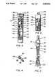
- a lancet injector 10including an elongate, generally cylindrical, housing 12 having a chamber or bore 14, and a lancet holder 16 slidable in the housing bore 14.
- Housing 12has a proximal end 18 in which is secured an end plug 20, and a distal end 22 covered by a removable cap 24 having a central opening 25.
- Cap 24is frictionally held in place by an annular bead 26 on the exterior of housing 12. In this way, the cap 24 can be snapped on and off the distal end 22 of the housing.
- the lancet holder 16as also seen in FIG. 3, includes a generally cylindrical portion or slide 28 having a lancet holding member 30 integrally connected to the distal end of the slide and a cylindrical extension or spring connector 32 at the proximal end of the slide.
- a spring 34shown as a coil spring, is disposed in the bore 14 between the holder 16 and the plug 20. Spring 34 is shown engaged between the holder and a lower end portion of the housing.
- the connector 32is provided with a series of external integral bumps 36 disposed in a spiral arrangement for threadedly receiving and holding the upper or distal end of coil spring 34. The spring 34 is threaded onto connector 32 until the end of the spring engages an integral stop bump 38.
- the end plug 20is shown provided with an integral extension or spring connector 40 having a spiral series of integral bumps 42 which threadedly receives and, as shown, holds the lower end of coil spring 34.
- the spring 34is threaded onto connector 40 until the end of the spring engages an integral stop bump 44.
- the spring connectors 32 and 40may be provided with suitable screw threads instead of the series of bumps or the ends of the spring 34 may be fixed to those connectors by other suitable means.
- the slide 28has a hole 46 in which is secured a manual slide control member or control latch 48 which extends through a slot, indicated generally at 50, in the sidewall of the housing 12.
- Latch 48extends to the exterior of the housing so that it provides an exterior manual control movable along the slot 50 for positioning the lancet holder 16 in a number of positions, as will be further described.
- the opposite ends of spring 34may be respectively threaded onto connectors 32 and 40 to provide unitary assembly, as seen in FIG. 3.
- This assemblycan be inserted into the proximal end of the housing 12.
- the free length of the spring 34is such that the unit may be manually rotated in the housing 12 by rotating plug 20 until the hole 46 appears in the slot 50.
- the latch 48may then be inserted through the slot and into hole 46.
- the latch 48is fixed in the hole 46, for example, it may be adhesively connected or solvent bonded to the sidewalls of hole 46.
- the holder 16 and connected latch 48are preferably spring biased in a counterclockwise direction of rotation, as viewed in the drawings, that is arcuately toward engagement with the left sidewall 52 of slot 50. This may be accomplished by providing the plug 20 and inner wall of the housing 12 at its proximal end with cooperating surfaces which permit insertion of the plug in a selected relative position with respect to slide 28.
- the plug 20is provided with a plurality of flats 54 which register with a plurality of flats 56 (FIG. 2) on the inner sidewall of bore 14 at the proximal end 18.
- the plug 20can be rotated counterclockwise so that the latch 48 engages a wall of slot 50, and then the plug 20 is further rotated in the same direction a slight amount relative to holder 16, and then the plug is inserted into the end 18 of the housing. Because of the cooperating flats 54 and 56, the plug cannot rotate and remains in its inserted position with the spring 34 resiliently biasing the holder 16 and latch 48 leftwardly or counterclockwise toward the left edge 52 of slot 50.
- the plug 20may be adhesively connected such as by applying a suitable adhesive to the plug prior to insertion or a suitable solvent where the plug and housing materials can be solvent bonded.
- the lancet holding member 30is shown as a sleeve or cylindrical barrel having inner sidewalls 58 which frictionally engage outer peripheral surfaces of a lancet 60.
- the lancet 60is shown including a base or handle 62, such as of plastic material, and a needle 64, such as a solid stainless steel pointed needle.
- the handle 62may be molded about the needle so that the tip of the needle extends outwardly beyond the upper end 66 of the handle.
- the lancet 60is shown including an integrally molded needle cap or sheath 68 covering the pointed needle tip.
- the connection between the sheath 68 and the handle 62is fragile so that by twisting or rotating the sheath relative to the handle, and then pulling the sheath from the needle tip, the needle tip is exposed.
- the depth of the lancet holding member 30is less than the length of the lancet handle 62 so that the upper portion, such as its upper one half, extends out of the holder and may be grasped, for example, between the thumb and finger, for inserting the lancet 60 into the holder 30 and for removing it after use.
- the bottom of the lancet bottoms on the bottom of the member 30as shown in FIG. 2.
- the slot 50is shaped so as to have a relative wide portion at the proximal end of the slot through which the control member 48 can be moved.
- the member 48is shown in its retracted position which places holder 16, member 30, and lancet 60 in the retracted position with the needle tip wholly within the housing 12.
- the control member 48is shown releasably latched in an axial recess 69 having a downward protrusion 70 for securely holding the lancet holder in the retracted position.
- the spring 34is in compression and exerting maximum longitudinal or linear spring force on the holder 16 in the distal direction. Also, the holder 16 is held in recess 69 against the biasing force of spring 34.
- control member 48When the control member 48 is manually unlatched from the retracted position (FIGS. 1 and 2), such as by moving it leftward over the protrusion 70 by applying pressure with a finger or thumb, the holder 16, due to the force of spring 34 and inertia, moves swiftly linearly or longitudinally and distally through housing bore 14 to a skin piercing position wherein the point of needle 64 extends through opening 25 in the end cap 24 and distally of the distal end of the housing as shown in phantom in FIG. 5. During this movement control member 48 moves along a slot portion 72.
- the holder 16 and lancet 60are quickly linearly retracted to a neutral position, that is, with the point of needle 64 retracted or withdrawn from the incision and within the housing 12 as shown in FIG. 5.
- Spring 34is sized relative to housing 12 such that when the holder 16 and control member 48 are in this neutral position, the spring 34 is at its free length position or neutral force position, that is, spring 34 is substantially neither in tension nor compression.
- the partsmay be proportioned such that the extent of distal travel of the lancet 60 may be limited by the engagement of the control member 48 with a sidewall 74 (FIGS. 1, 5 and 6) of the slot 50, the indicated phantom position of member 48 in FIG. 5, or, if desired, by the engagement of the upper end 66 of the lancet handle with the inner side of the end wall of cap 24. In some cases, the construction may allow the end 66 to strike the skin.
- the holder 16 and lancet holder 30may be moved to a lancet access or unloading and loading position, the position shown in FIG. 6. This is accomplished by removing cap 24 and urging the control member 48 rightwardly against the bias force from its neutral position of FIG. 5 and into an elongate slot portion 76 of slot 50, then longitudinally or linearly upwardly and distally into an enlarged slot portion 78, and then leftwardly into the access position in a recess 80 in slot 50 and which has a distally extending sidewall 82 holding the member 48 in place.
- the coil spring 34is tensioned, that is, stretched beyond its neutral or free length condition of FIG. 5.
- the tensioned spring 34tends to maintain the member 48 urged downwardly in groove 80 so that it cannot move out of the groove.
- the lancet holding member 30extends through and above the upper or distal open end of the housing 12. In this position the upper portion of the lancet 60 may be grasped by the handle 62 and pulled upwardly to remove it from the member 30. A new lancet may then be inserted into the holder 30 until it bottoms against the inner bottom wall of the member 30. After a new lancet is inserted into the holding member in the access position of FIG. 6, the needle sheath such as sheath 68 (FIG. 4) is removed to expose the pointed needle tip, and then the external control member 48 is manually moved out of recess 80 into the enlarged slot portion 78.
- sheathsuch as sheath 68 (FIG. 4)
- the member 48is moved rightwardly against the rotary bias force of spring 34 into an elongate slot 76 where the force of tensioned spring 34 swiftly moves the slide 28 proximally longitudinally or axially of the housing so that it moves back into its neutral position shown in FIG. 5, the bias force of the spring urging it against the left edge 52 of the slot 50.
- the cap 24may then be snapped back onto the distal end of housing 12.
- a new lancetsuch as lancet 60
- lancet holder 30When the control member 48 is positioned in the lancet access position indicated in FIG. 6.
- the needle sheathsuch as sheath 68 (FIG. 4) is removed from the lancet, and the control member 48 is manually moved out of recess 80 so that the tensioned spring 34 withdraws the lancet and slide 48 through slot portion 76 to the neutral position indicated in FIG. 5.
- the cap 24 or a new capmay now be placed over the distal end of the housing 12.
- control member 48is manually moved proximally or downwardly in slot portion 72 compressing coil spring 34 and then over to recess 68 to place the member 48 and holder 16 in a latched retracted or cocked position as shown in FIGS. 1 and 2.
- the housing 12may now be hand grasped and the end cap 24 pressed against the skin, such as the skin of the finger, of the person whose blood is to be tested.
- the control member 48may now be forced out or the retracted position so that the force of spring 34 and the inertia of the lancet 60 and lancet holder 16 effect piercing of the skin by the needle tip of the lancet and quick removal of the needle from the skin incision to the neutral position as indicated in FIG. 5.
- the cap 24may now be removed and the control member 48 moved to the lancet access position as shown in FIG. 6 so that the used lancet may be easily and safely removed from the injector 10 and discarded.
- a new lancetmay be inserted into the holding member 30 and the control member again moved to the neutral position of FIG. 5 so that the device is again ready to be used to effect skin piercing.
- the blood flow caused by the lancet piercing the skinmay be collected in a capillary tube or pipette and subjected to clinical testing. For example, at times, glucose testing may be done relatively often in the case of diabetics. Also, such testing may be self-performed such as in the home for monitoring blood glucose.
- the lancet injector device 10effects a very quick incision and withdrawal of the lancet needle so that patient discomfort is minimized. Since the lancet is substantially hidden by the housing, one does not see the lancet point during use and the anxiety of the patient is generally substantially less than where one sees the lancet point. Also, the injector 10 is easy to operate.
- the injector 10requires only one functional spring while operating in a simple and highly effective manner.
- the spring 34is shown as a single coil propulsion compression spring which propels the lancet holder 16 for the skin piercing operation.
- Spring 34provides the force for piercing the skin as well as swiftly withdrawing the lancet from the incision.
- the spring 34is also tensioned when the device is in its lancet access position (FIG. 6) so that its force is also used to quickly withdraw the exposed lancet needle to the neutral position (FIG. 5) when the control member 48 is moved accordingly.
- spring 34provides the arcuate biasing force normally urging the slide 48 leftwardly when such bias is employed in the device.
- the construction of device 10requires few moving parts and, in general, is simple and economical to make and use.
- the housing 12, holder 16 and plug 20may be economically molded from any suitable plastic, for example, from a copolymer made from acrylonitrile, butadiene, and styrene (ABS), or polypropylene.
- the cap 24may also be made from a suitable plastic such as polypropylene. While a snap-on type cap 24 is shown, other cap constructions allowing attachment and removal are possible.”
- a problem with the lancet injectors of the two above-referenced patentsis that the lancet tip must be manually removed from the lancet holder 30 after the lancet has been retracted from the skin of the subject. During this removal process, the lancet tip is exposed and in close proximity to the fingers of the person removing the lancet tip. This increases the possibility that the person removing the lancet may become inadvertently stuck by the lancet tip. In addition to the dangers inherent in puncture wounds, there is the additional danger that the person removing the lancet tip may become infected with a blood borne disease transmitted through the stick from a contaminated lancet tip. These are of course problems to be avoided.
- a lancet injectorhaving a lancet tip that may be automatically removed from the lancet injector after piercing and being retracted from the skin of the subject.
- the present inventionis used in combination with a lancet injector including a generally tubular housing having a patient contacting or distal end and an opposed distal end.
- the inventionalso includes, within the housing, a lancet holder having a central bore coaxial with the central axis of the housing and a spring that biases the lancet holder toward the distal end of the housing.
- the lancet holderfrictionally holds the lancet so that the lancet needle is aligned with the central axis and directed toward the distal end of the housing.
- An external control memberis connected to the holder through a slot in the housing.
- the control memberis constrained to move along the slot because of the contact between the slot and the connection of the holder and control member.
- the control membermoves the holder to a retracted position against the bias of the spring.
- a separation recessextends from the slot along the housing toward the proximal end of the housing to allow the control member to move proximally in the separation recess.
- the separation recesshas a proximally extending retention recess having means to retain the lancet holder in its most proximal position
- a pinextends from the proximal end of the housing along the central axis of the housing toward the central bore of the holder.
- the pinmoves into the central bore of the holder.
- the pin in the central bore of the lancet holdercomes into contact with the lancet.
- the pinstops proximal movement of the lancet during further proximal movement of the control member in the separation recess thereby causing the lancet to be pushed to the edge of frictional contact with the lancet holder. Movement of the control member proximally into the retention recess moves the lancet out of frictional contact with the holder.
- the distal end of the lancet injectoris directed downward into an appropriate sharps container.
- the lancetnow free from frictional retaining contact with the lancet holder, falls from the lancet injector into the sharps container.
- FIG. 1is a side elevational view of a prior art lancet injector device
- FIG. 2is a cross-sectional view of the injector device of FIG. 1;
- FIG. 3is a side elevational view of an assembly of parts employed in the injector device of FIG. 1;
- FIG. 4is a perspective view of the lancet of FIG. 1;
- FIG. 5is a fragmentary side elevational view showing the upper portion of the injector device of FIG. 1 and illustrating the lancet in phantom in its skin piercing position, and the lancet and holder in the neutral position;
- FIG. 6is a fragmentary side elevational view of the upper portion of the injector device of FIG. 1 showing the lancet holder and in its lancet loading and unloading position with the lancet removed from the device;
- FIG. 7is a side elevational view of the lancet injector device of FIG. 1 incorporating the present invention.
- FIG. 8is a cross-sectional view of the injector device of FIG. 7;
- FIG. 9ais a side elevational view of the pin of the injector device of FIG. 7;
- FIG. 9bis a cross-sectional view of the pin of FIG. 9a through line B--B;
- FIG. 9cis a cross-sectional view of the pin of FIG. 9a through line A--A
- FIG. 10is a cross-sectional view of the lancet holder of the lancet injector device of FIG. 7;
- FIG. 11ais a cross-sectional view of the lancet injector device of FIG. 7 in the "load" position;
- FIG. 11bis a cross-sectional view of the lancet injector device of FIG. 7 in the "neutral" position;
- FIG. 11cis a cross-sectional view of the lancet injector device of FIG. 7 in the "retracted" position;
- FIG. 11dis a cross-sectional view of the lancet injector device of FIG. 7 in the "separation position";
- FIG. 12is a side elevational view of the preferred embodiment of the lancet injector device having a retention recess
- FIG. 13is an enlarged view of the separation recess and retention recess of the device of FIG. 12 circled in phantom in FIG. 12;
- FIG. 14is cross-sectional view of the control member of the embodiment of FIG. 12;
- FIG. 15ais a schematic embodiment of the control member of FIG. 14 moving into the retention recess of FIG. 13;
- FIG. 15bis a schematic view of the control member of FIG. 14 in position within the retention recess of FIG. 13;
- FIG. 16is a side elevational view of an alternate embodiment of the retention recess of the present invention.
- FIG. 17ais a side elevational view of an alternate embodiment of the retention device of the present invention before the device is locked in the retaining position;
- FIG. 17bis a side elevational view of the embodiment of FIG. 17a wherein the control member is locked in position within the retention recess.
- FIG. 18is a side elevational view of an alternate embodiment of the invention.
- the lancet injector device of FIG. 1is shown with slot 50 modified by the inclusion of a separation recess 84 extending axially along housing 12 opposite axial recess 69.
- Separation recess 84is sufficiently wide to allow control member 48 to be moved into and along it.
- control member 48moves along separation recess 84, lancet holder 16 moves along with it in bore 14 of housing 12.
- lancet holder 16is drawn proximally toward end plug 20.
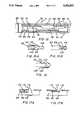
- the lancet injection device of FIG. 1is also modified in the present invention by placing a central bore 94 through lancet holder 16 as shown in FIG. 10.
- Central bore 94extends entirely through lancet holder 16 including extending through slide 28, spring connector 32 and lancet holding member 30.
- Central bore 94preferably has an enlarged proximal end 96 within spring connector 32 that tapers to the distal end 97 of central bore 94. Because central bore 94 extends entirely through lancet holder 16, it provides access to the bottom end 67 of lancet 60 through bore 94 when lancet 60 is placed in position in lancet holding member 30.
- a pin 86(FIG. 9a) is molded in part with end plug 20 at the proximal end 18 of housing 12 within spring connector 40 as shown in FIG. 8.
- Pin 86includes an enlarged part 88 and a narrow part 90.
- Enlarged part 88is preferably "cross-shaped" in cross-section as shown in FIG. 9b and is of sufficient stiffness and rigidity to support narrow part 90 and to provide a connection between narrow part 90 and spring connector 40.
- enlarged part 88is preferably "cross-shaped" in cross-section, other cross-sections are possible and within the scope of the invention so long as they perform the functions of supporting and connecting narrow part 90 as described above.
- An advantage of the "cross-shaped" cross-sectionis that the amount of material needed to mold enlarged part 88 is reduced as compared to a more solid cross-section.
- Narrow part 90is preferably circular in cross-section as shown in FIG. 9c. This circular shape facilitates the insertion of narrow part 90 through the central bore 94 as will be described hereafter.
- pin 86is positioned within and along the central axis of spring 34 and extends from end plug 20 to a point where the most distal end of narrow part 90 just contacts the bottom end 67 of lancet when control member 48 is in the "retracted” position.
- narrow part 90extends into and through the central bore 94.
- FIGS. 11a-dshow cross-sectional views of the present invention in operation.
- control member 48has been moved forward to the "load” position.
- a lancet 60has been placed in position in lancet holding member 30 so that the outer walls of lancet 60 are in frictional contact with inner sidewalls 58 of lancet holding member 30.
- pin 86does not protrude through the central bore 94 of lancet holder 16.
- control member 48After lancet needle 64 has punctured skin of the subject as described above and has returned to the "neutral" position shown in FIG. 11b, control member 48 is retracted proximally through slot 50 to the "retracted” position shown in FIG. 11c. In the “retracted” position, spring 34 is slightly compressed providing a bias against lancet holder 16 which pushes control member 48 into contact with axial recess 69. Contact between control member 48 and axial recess 69 holds lancet holder 16 in the "retracted” position. At this time, or previously when control member 48 was in the "neutral” position after having punctured the skin of the subject, the removable cap 24 is removed from the distal end 22 of housing 12.
- control member 48When control member 48 is moved to the "retracted” position as shown in FIG. 11c, the narrow part 90 of pin 86 moves through the enlarged proximal end 96 and through central bore 94 of lancet holder 16 into a position nearly in contact with the bottom end 67 of lancet 60. In this position, any further proximal movement of control member 48 brings the most distal end of narrow part 90 into contact with bottom end 67 of lancet 60.
- control member 48As shown in FIG. 11d, as control member 48 is moved proximally into separation recess 84, the distal end of narrow part 90 comes into contact with the bottom end 67 of lancet 60. As control member 48 is moved further proximally, contact between the distal end of narrow part 90 and lower end 67 of lancet 60 causes lancet 60 to become separated from its frictional contact with lancet holding member 30. Further, as control member 48 is moved proximally from the "retracted” position shown in FIG. 11c, spring 34 becomes highly compressed therefore strongly biasing control member 48 toward the "retracted” position shown in FIG. 11c. Also, as can be seen in FIG. 11d, when control member 48 is moved to its most proximal position known as the "separation position", the enlarged part 88 of pin 86 extends into the enlarged proximal end 96 of lancet holder 16.
- control member 48Any premature release of control member 48 before it is moved and secured in retention recess 98 will cause lancet holder 16 to move distally under the bias of spring 34 but, because lancet 60 is still in frictional contact with lancet holding member 30, lancet 60 will be retained in frictional contact with lancet holding member 30 when control member 48 comes into contact with axial recess 69.
- FIGS. 12-15A preferred embodiment for retention recess 98 is shown in FIGS. 12-15.
- separation recess 84is modified by including a retention recess 98 extending proximally and axially along housing 12 from the most proximal end of separation recess 84.
- retention recess 98includes a narrow bore 100 that opens into an expanded roughly circular shaped proximal stop 102.
- control member 48is modified in cross-section as shown in FIG. 14 to include an expanded end 104 at the most proximal end of control member 48.
- the cross-sectional shape of expanded end 104is approximately the same as the interior shape of proximal stop 102.
- the transverse width of control member 48 distal to expanded end 104is approximately the same as the inside diameter of narrow bore 100.
- at least the part of control member 48 that will move proximally into contact with retention recess 98should be made of a resilient material for a purpose that will be explained hereafter.
- the resilient material of control member 48is preferably the same resilient material as housing 12 as explained above.
- FIG. 15ashows the control member 48 moving proximally from separation recess 84 into retention recess 98.
- proximal expanded end 104moves through narrow bore 100, because the transverse width of expanded end 104 is wider than narrow bore 100, expanded end 104 deforms to pass through narrow bore 100 into proximal stop 102 as shown in FIG. 15b. Because expanded end 104 is no longer compressed within bore 100, it expands to its full non-deformed dimensions that closely correspond to the shape of proximal stop 102.
- Spring 34biases control member 48 distally in retention recess 98 so that expanded end 104 comes into frictional contact with the material of housing 12 narrowing from proximal stop 102 to form narrow bore 100. This frictional contact between expanded end 104 and the entrance to narrow bore 100 retains control member 48 at the proximal end of retention recess 98 despite the bias of spring 34.
- control member 48When it is desired to release control member 48 so that the bias of spring 34 causes control member 48 to move back into contact with axial recess 69, distal pressure is placed on control member 48. This distal pressure causes expanded end 104 to deform to move into narrow bore 100 thereby allowing control member 48 to pass through bore 100.
- the bias of spring 34moves control member 48, and by extension holder 16, proximally until control member 48 contacts axial recess 69.
- proximal stop 102 and expanded end 104have been described as being roughly circular, any other shape may be used so long as the transverse width of expanded end 104 is larger than the width of narrow bore 100.
- FIG. 16shows a modification of the embodiment shown in FIGS. 12-15.
- narrow bore 100is formed by a protrusion 106 pivotally attached to housing 12 at pivot point 108.
- Protrusion 106is integrally made with housing 12 and pivot point 108 is preferably a narrow piece of the material of housing 12 so that protrusion 106 flexes with transverse movement of protrusion 106. Transverse pressure on protrusion 106 causes it to move away from retention recess 98.
- control member 48When it is desired to release control member 48 so that the bias of spring 34 causes control member 48 to move back into contact with axial recess 69, distal pressure is placed on control member 48. This distal pressure causes protrusion 106 to move away from expanded end 104 thereby allowing control member 48 to pass through bore 100.
- the bias of spring 34moves control member 48, and by extension holder 16, proximally until control member 48 contacts axial recess 69.
- control member 48has a protrusion 110 extending transverse to the elongated axis of control member 48.
- a slot 112extends away from retention recess 98 into housing 12 so that a lip 114 is formed on the distal end of slot 112.
- control member 48In operation, as control member 48 is moved sufficiently proximally into recess 98, protrusion 110 moves past lip 114. At this point, control member 48 can be moved toward slot 112 so that protrusion 110 comes into contact with lip 114. When proximal pressure on control member 48 is removed, the bias of spring 34 will place protrusion 110 into frictional contact with lip 114 thereby retaining control member 48 in position within retention recess 98. When it is desired to allow control member 48 to move back into contact with axial recess 69, control member 48 is moved away from slot 112 so that 110 moves out of contact with lip 114. At this time, spring 34 then moves control member 48 distally.
- FIG. 18A further embodiment of the invention is shown in FIG. 18.
- a retention protrusion 116is formed between separation recess 84 and retention recess 98.
- retention recess 98is formed at an angle to separation recess 84 although retention recess 98 may also be formed along a common linear axis with separation recess 84.
- Control member 48is moved past retention protrusion 116 into retention recess 98. There, the bias of spring 34 pushes control member 48 into contact with retention protrusion 116. Frictional contact between control member 48 and retention protrusion 116 holds control member 48 in position within retention recess 98.
- control member 48When control member 48 is to be moved back into contact with axial recess 69, control member 48 is moved along retention protrusion 116 until it clears retention protrusion 116. At this point, the bias of spring 34 moves control member 48 distally.
Landscapes
- Health & Medical Sciences (AREA)
- Life Sciences & Earth Sciences (AREA)
- Heart & Thoracic Surgery (AREA)
- Medical Informatics (AREA)
- Biophysics (AREA)
- Pathology (AREA)
- Engineering & Computer Science (AREA)
- Biomedical Technology (AREA)
- Hematology (AREA)
- Physics & Mathematics (AREA)
- Molecular Biology (AREA)
- Surgery (AREA)
- Animal Behavior & Ethology (AREA)
- General Health & Medical Sciences (AREA)
- Public Health (AREA)
- Veterinary Medicine (AREA)
- Dermatology (AREA)
- Measurement Of The Respiration, Hearing Ability, Form, And Blood Characteristics Of Living Organisms (AREA)
Abstract
Description
Claims (31)
Priority Applications (1)
| Application Number | Priority Date | Filing Date | Title |
|---|---|---|---|
| US08/004,885US5282822A (en) | 1993-01-19 | 1993-01-19 | Lancet ejector for lancet injector |
Applications Claiming Priority (1)
| Application Number | Priority Date | Filing Date | Title |
|---|---|---|---|
| US08/004,885US5282822A (en) | 1993-01-19 | 1993-01-19 | Lancet ejector for lancet injector |
Publications (1)
| Publication Number | Publication Date |
|---|---|
| US5282822Atrue US5282822A (en) | 1994-02-01 |
Family
ID=21713007
Family Applications (1)
| Application Number | Title | Priority Date | Filing Date |
|---|---|---|---|
| US08/004,885Expired - LifetimeUS5282822A (en) | 1993-01-19 | 1993-01-19 | Lancet ejector for lancet injector |
Country Status (1)
| Country | Link |
|---|---|
| US (1) | US5282822A (en) |
Cited By (136)
| Publication number | Priority date | Publication date | Assignee | Title |
|---|---|---|---|---|
| US5487748A (en)* | 1992-04-01 | 1996-01-30 | Owen Mumford Limited | Blood sampling device |
| US5540709A (en)* | 1991-11-12 | 1996-07-30 | Actimed Laboratories, Inc. | Lancet device |
| US5554166A (en)* | 1993-06-21 | 1996-09-10 | Boehringer Mannheim Gmbh | Blood lancet device for withdrawing blood for diagnostic purposes |
| US5637100A (en)* | 1992-11-27 | 1997-06-10 | Daikyo Seiko, Ltd. | Syringe-cum-container |
| WO1997042885A1 (en)* | 1996-05-17 | 1997-11-20 | Mercury Diagnostics, Inc. | Methods and apparatus for sampling body fluid |
| US5857983A (en)* | 1996-05-17 | 1999-01-12 | Mercury Diagnostics, Inc. | Methods and apparatus for sampling body fluid |
| US6015392A (en)* | 1996-05-17 | 2000-01-18 | Mercury Diagnostics, Inc. | Apparatus for sampling body fluid |
| US6027459A (en)* | 1996-12-06 | 2000-02-22 | Abbott Laboratories | Method and apparatus for obtaining blood for diagnostic tests |
| US6183489B1 (en) | 1996-05-17 | 2001-02-06 | Amira Medical | Disposable element for use in a body fluid sampling device |
| US20030083686A1 (en)* | 2001-06-12 | 2003-05-01 | Freeman Dominique M. | Tissue penetration device |
| US6558402B1 (en) | 1999-08-03 | 2003-05-06 | Becton, Dickinson And Company | Lancer |
| US20030088261A1 (en)* | 2000-01-28 | 2003-05-08 | Stat Medical Device Inc. | Adjustable tip for a lancet device and method |
| US20030199907A1 (en)* | 2002-04-19 | 2003-10-23 | Pelikan Technologies, Inc. | Method and apparatus for penetrating tissue |
| US20030199899A1 (en)* | 2002-04-19 | 2003-10-23 | Pelikan Technologies, Inc. | Method and apparatus for penetrating tissue |
| US20030199904A1 (en)* | 2002-04-19 | 2003-10-23 | Pelikan Technologies, Inc. | Method and apparatus for penetrating tissue |
| US20030199905A1 (en)* | 2002-04-19 | 2003-10-23 | Pelikan Technologies, Inc. | Method and apparatus for penetrating tissue |
| US20030199906A1 (en)* | 2002-04-19 | 2003-10-23 | Pelikan Technologies, Inc. | Method and apparatus for penetrating tissue |
| US20030199911A1 (en)* | 2002-04-19 | 2003-10-23 | Pelikan Technologies, Inc. | Method and apparatus for penetrating tissue |
| US20030199901A1 (en)* | 2002-04-19 | 2003-10-23 | Pelikan Technologies, Inc. | Method and apparatus for penetrating tissue |
| US20030199898A1 (en)* | 2002-04-19 | 2003-10-23 | Pelikan Technologies, Inc. | Method and apparatus for penetrating tissue |
| US20030199908A1 (en)* | 2002-04-19 | 2003-10-23 | Pelikan Technologies, Inc. | Method and apparatus for penetrating tissue |
| US20030225430A1 (en)* | 1998-06-11 | 2003-12-04 | Stat Medical Devices Inc. | Lancet having adjustable penetration depth |
| US6706000B2 (en) | 1997-11-21 | 2004-03-16 | Amira Medical | Methods and apparatus for expressing body fluid from an incision |
| US20040102803A1 (en)* | 2002-04-19 | 2004-05-27 | Pelikan Technologies, Inc. | Method and apparatus for a multi-use body fluid sampling device |
| US20040162506A1 (en)* | 1996-05-17 | 2004-08-19 | Duchon Brent G. | Body fluid sampling device and methods of use |
| US20040181249A1 (en)* | 2003-03-10 | 2004-09-16 | Pathway Medical Technologies, Inc. | Bearing system to support a rotatable operating head in an intracorporeal device |
| US20040236362A1 (en)* | 2003-05-20 | 2004-11-25 | Stat Medical Devices, Inc. | Adjustable lancet device and method |
| US20040243165A1 (en)* | 2001-07-11 | 2004-12-02 | Masufumi Koike | Lancet and piercing device |
| US20040249406A1 (en)* | 2003-03-20 | 2004-12-09 | Griffin Carl E. | Lancing device with decoupled lancet |
| US20040254599A1 (en)* | 2003-03-25 | 2004-12-16 | Lipoma Michael V. | Method and apparatus for pre-lancing stimulation of puncture site |
| US20040260326A1 (en)* | 2003-03-24 | 2004-12-23 | Lipoma Michael V. | Lancing device with floating lancet |
| US20050038465A1 (en)* | 2003-08-15 | 2005-02-17 | Stat Medical Devices, Inc. | Adjustable lancet device and method |
| US20050101981A1 (en)* | 2001-06-12 | 2005-05-12 | Don Alden | Method and apparatus for lancet launching device intergrated onto a blood-sampling cartridge |
| US20050165435A1 (en)* | 2002-03-22 | 2005-07-28 | Gyrus Ent L.L.C. | Powered surgical apparatus, method of manufacturing powered surgical apparatus, and method of using powered surgical apparatus |
| US6969359B2 (en) | 1997-11-21 | 2005-11-29 | Roche Diagnostics Operations, Inc. | Body fluid sampling device |
| US20050288699A1 (en)* | 2004-06-29 | 2005-12-29 | Stat Medical Devices, Inc. | Adjustable disposable/single-use lancet device and method |
| US20060106411A1 (en)* | 2004-11-16 | 2006-05-18 | Stat Medical Devices Inc. | Adjustable disposable/single-use blade lancet device and method |
| US20060116705A1 (en)* | 2004-11-30 | 2006-06-01 | Stat Medical Devices, Inc. | Disposable or single-use lancet device and method |
| US7105006B2 (en) | 2003-08-15 | 2006-09-12 | Stat Medical Devices, Inc. | Adjustable lancet device and method |
| US20060204399A1 (en)* | 2002-12-30 | 2006-09-14 | Freeman Dominique M | Method and apparatus using optical techniques to measure analyte levels |
| US20060241668A1 (en)* | 2005-01-28 | 2006-10-26 | Stat Medical Devices, Inc. | Multi-lancet unit, method and lancet device using the multi-lancet unit, and method of assembling and/or making the multi-lancet unit |
| US20070095178A1 (en)* | 2005-11-03 | 2007-05-03 | Stat Medical Devices, Inc. | Disposable/single-use blade lancet device and method |
| US20070118081A1 (en)* | 2003-09-17 | 2007-05-24 | Dali Medical Devices Ltd. | Automatic needle device |
| WO2007021979A3 (en)* | 2005-08-12 | 2007-05-24 | Bayer Healthcare Llc | Integrated test system for monitoring bodily fluids |
| US7232451B2 (en) | 2002-04-19 | 2007-06-19 | Pelikan Technologies, Inc. | Method and apparatus for penetrating tissue |
| US7258693B2 (en) | 2002-04-19 | 2007-08-21 | Pelikan Technologies, Inc. | Device and method for variable speed lancet |
| US20070244499A1 (en)* | 2002-04-19 | 2007-10-18 | Barry Briggs | Methods and apparatus for lancet actuation |
| US7297151B2 (en) | 2002-04-19 | 2007-11-20 | Elikan Technologies, Inc. | Method and apparatus for body fluid sampling with improved sensing |
| US20070293747A1 (en)* | 1996-05-17 | 2007-12-20 | Roche Diagnostics Operations, Inc. | Methods and apparatus for sampling and analyzing body fluid |
| US20070299459A1 (en)* | 2006-06-26 | 2007-12-27 | X-Sten Corp. | Percutaneous Tissue Access Device |
| US7316700B2 (en) | 2001-06-12 | 2008-01-08 | Pelikan Technologies, Inc. | Self optimizing lancing device with adaptation means to temporal variations in cutaneous properties |
| EP1764047A3 (en)* | 1996-05-17 | 2008-01-23 | Roche Diagnostics Operations, Inc. | Apparatus for sampling body fluid |
| US7344507B2 (en) | 2002-04-19 | 2008-03-18 | Pelikan Technologies, Inc. | Method and apparatus for lancet actuation |
| US7344894B2 (en) | 2001-10-16 | 2008-03-18 | Agilent Technologies, Inc. | Thermal regulation of fluidic samples within a diagnostic cartridge |
| US20080082116A1 (en)* | 2006-06-15 | 2008-04-03 | Abbott Diabetes Care Inc. | Lancing Devices Having Lancet Ejection Assembly |
| US20080092241A1 (en)* | 2006-10-11 | 2008-04-17 | Media Machines, Inc. | Provision and use of digital rights data for embedded content over networked systems |
| US7371247B2 (en) | 2002-04-19 | 2008-05-13 | Pelikan Technologies, Inc | Method and apparatus for penetrating tissue |
| US20080149524A1 (en)* | 2003-03-27 | 2008-06-26 | Rademaker William B | Food containers including dental cleaning devices and other personal care items |
| US7410468B2 (en) | 2002-04-19 | 2008-08-12 | Pelikan Technologies, Inc. | Method and apparatus for penetrating tissue |
| US20080243159A1 (en)* | 2007-03-30 | 2008-10-02 | Stat Medical Devices, Inc. | Lancet device with combined trigger and cocking mechanism and method |
| US20080243161A1 (en)* | 2007-03-30 | 2008-10-02 | Ramzi Abulhaj | Disposable lancet with re-cocking prevention means |
| US20080308441A1 (en)* | 2007-06-15 | 2008-12-18 | Ultimed Inc. | Lancet dispenser |
| US20080319291A1 (en)* | 2000-11-21 | 2008-12-25 | Dominique Freeman | Blood Testing Apparatus Having a Rotatable Cartridge with Multiple Lancing Elements and Testing Means |
| US20090005664A1 (en)* | 2000-11-21 | 2009-01-01 | Dominique Freeman | Blood Testing Apparatus Having a Rotatable Cartridge with Multiple Lancing Elements and Testing Means |
| US20090024009A1 (en)* | 2002-04-19 | 2009-01-22 | Dominique Freeman | Body fluid sampling device with a capacitive sensor |
| US7485128B2 (en) | 2002-04-19 | 2009-02-03 | Pelikan Technologies, Inc. | Method and apparatus for penetrating tissue |
| US7491178B2 (en) | 2002-04-19 | 2009-02-17 | Pelikan Technologies, Inc. | Method and apparatus for penetrating tissue |
| US7524293B2 (en) | 2002-04-19 | 2009-04-28 | Pelikan Technologies, Inc. | Method and apparatus for penetrating tissue |
| US20090112123A1 (en)* | 2002-04-19 | 2009-04-30 | Dominique Freeman | Method for penetrating tissue |
| US20090118752A1 (en)* | 2001-06-08 | 2009-05-07 | Edward Perez | Devices and methods for expression of bodily fluids from an incision |
| US7537571B2 (en) | 2001-06-12 | 2009-05-26 | Pelikan Technologies, Inc. | Integrated blood sampling analysis system with multi-use sampling module |
| US7547287B2 (en) | 2002-04-19 | 2009-06-16 | Pelikan Technologies, Inc. | Method and apparatus for penetrating tissue |
| US7563232B2 (en) | 2002-04-19 | 2009-07-21 | Pelikan Technologies, Inc. | Method and apparatus for penetrating tissue |
| USD598549S1 (en) | 2008-09-16 | 2009-08-18 | Vertos Medical, Inc. | Surgical trocar |
| US7604592B2 (en) | 2003-06-13 | 2009-10-20 | Pelikan Technologies, Inc. | Method and apparatus for a point of care device |
| US7648468B2 (en) | 2002-04-19 | 2010-01-19 | Pelikon Technologies, Inc. | Method and apparatus for penetrating tissue |
| US7666149B2 (en) | 1997-12-04 | 2010-02-23 | Peliken Technologies, Inc. | Cassette of lancet cartridges for sampling blood |
| USD612051S1 (en) | 2008-12-18 | 2010-03-16 | Facet Technologies, Llc | Lancing device |
| US7682318B2 (en) | 2001-06-12 | 2010-03-23 | Pelikan Technologies, Inc. | Blood sampling apparatus and method |
| US7699791B2 (en) | 2001-06-12 | 2010-04-20 | Pelikan Technologies, Inc. | Method and apparatus for improving success rate of blood yield from a fingerstick |
| US20100106058A1 (en)* | 1996-05-17 | 2010-04-29 | Douglas Joel S | Blood and interstitial fluid sampling device |
| US20100160943A1 (en)* | 2008-12-18 | 2010-06-24 | Facet Technologies, Llc | Lancing device and lancet |
| US7758516B2 (en) | 2001-09-26 | 2010-07-20 | Roche Diagnostics Operations, Inc. | Method and apparatus for sampling bodily fluid |
| US20100187132A1 (en)* | 2008-12-29 | 2010-07-29 | Don Alden | Determination of the real electrochemical surface areas of screen printed electrodes |
| US7780631B2 (en) | 1998-03-30 | 2010-08-24 | Pelikan Technologies, Inc. | Apparatus and method for penetration with shaft having a sensor for sensing penetration depth |
| US7822454B1 (en) | 2005-01-03 | 2010-10-26 | Pelikan Technologies, Inc. | Fluid sampling device with improved analyte detecting member configuration |
| US20100274273A1 (en)* | 2007-06-19 | 2010-10-28 | Steven Schraga | Lancet device with depth adjustment and lancet removal system and method |
| US7841991B2 (en) | 1996-05-17 | 2010-11-30 | Roche Diagnostics Operations, Inc. | Methods and apparatus for expressing body fluid from an incision |
| US7850621B2 (en) | 2003-06-06 | 2010-12-14 | Pelikan Technologies, Inc. | Method and apparatus for body fluid sampling and analyte sensing |
| US7892185B2 (en) | 2002-04-19 | 2011-02-22 | Pelikan Technologies, Inc. | Method and apparatus for body fluid sampling and analyte sensing |
| US7892183B2 (en) | 2002-04-19 | 2011-02-22 | Pelikan Technologies, Inc. | Method and apparatus for body fluid sampling and analyte sensing |
| US7901362B2 (en) | 2002-04-19 | 2011-03-08 | Pelikan Technologies, Inc. | Method and apparatus for penetrating tissue |
| USD634426S1 (en) | 2010-04-08 | 2011-03-15 | Facet Technologies, Llc | Lancing device |
| US7909778B2 (en) | 2002-04-19 | 2011-03-22 | Pelikan Technologies, Inc. | Method and apparatus for penetrating tissue |
| US20110098735A1 (en)* | 2009-10-22 | 2011-04-28 | Facet Technologies, Llc | Lancing device with improved guidance assembly |
| US20110160759A1 (en)* | 2007-02-09 | 2011-06-30 | Stat Medical Devices, Inc. | Multi-lancet unit, method and lancet device using the multi-lancet unit, and method of assembling and/or making the multi-lancet unit |
| US7976476B2 (en) | 2002-04-19 | 2011-07-12 | Pelikan Technologies, Inc. | Device and method for variable speed lancet |
| US7985216B2 (en) | 2004-03-16 | 2011-07-26 | Dali Medical Devices Ltd. | Medicinal container engagement and automatic needle device |
| US8043318B2 (en) | 2007-02-08 | 2011-10-25 | Stat Medical Devices, Inc. | Push-button lance device and method |
| US8197421B2 (en) | 2002-04-19 | 2012-06-12 | Pelikan Technologies, Inc. | Method and apparatus for penetrating tissue |
| US8221334B2 (en) | 2002-04-19 | 2012-07-17 | Sanofi-Aventis Deutschland Gmbh | Method and apparatus for penetrating tissue |
| US8262614B2 (en) | 2003-05-30 | 2012-09-11 | Pelikan Technologies, Inc. | Method and apparatus for fluid injection |
| US8267870B2 (en) | 2002-04-19 | 2012-09-18 | Sanofi-Aventis Deutschland Gmbh | Method and apparatus for body fluid sampling with hybrid actuation |
| US20120245559A1 (en)* | 2011-03-25 | 2012-09-27 | Stanley Kruger | Grip for self-injectable device |
| US8282576B2 (en) | 2003-09-29 | 2012-10-09 | Sanofi-Aventis Deutschland Gmbh | Method and apparatus for an improved sample capture device |
| US8337421B2 (en) | 2001-06-12 | 2012-12-25 | Sanofi-Aventis Deutschland Gmbh | Tissue penetration device |
| US8353924B2 (en) | 1999-11-02 | 2013-01-15 | Stat Medical Devices, Inc. | Single use lancet assembly |
| US8360992B2 (en) | 2002-04-19 | 2013-01-29 | Sanofi-Aventis Deutschland Gmbh | Method and apparatus for penetrating tissue |
| US8376998B2 (en) | 2003-09-17 | 2013-02-19 | Elcam Medical Agricultural Cooperative Association Ltd. | Automatic injection device |
| US8652831B2 (en) | 2004-12-30 | 2014-02-18 | Sanofi-Aventis Deutschland Gmbh | Method and apparatus for analyte measurement test time |
| US8668656B2 (en) | 2003-12-31 | 2014-03-11 | Sanofi-Aventis Deutschland Gmbh | Method and apparatus for improving fluidic flow and sample capture |
| US8702624B2 (en) | 2006-09-29 | 2014-04-22 | Sanofi-Aventis Deutschland Gmbh | Analyte measurement device with a single shot actuator |
| US8715309B2 (en) | 2002-04-29 | 2014-05-06 | Steven Schraga | Lancet device |
| US8721671B2 (en) | 2001-06-12 | 2014-05-13 | Sanofi-Aventis Deutschland Gmbh | Electric lancet actuator |
| US8814896B2 (en) | 1999-11-02 | 2014-08-26 | Stat Medical Devices, Inc. | Single use lancet assembly |
| US8828203B2 (en) | 2004-05-20 | 2014-09-09 | Sanofi-Aventis Deutschland Gmbh | Printable hydrogels for biosensors |
| US8965476B2 (en) | 2010-04-16 | 2015-02-24 | Sanofi-Aventis Deutschland Gmbh | Tissue penetration device |
| US9144401B2 (en) | 2003-06-11 | 2015-09-29 | Sanofi-Aventis Deutschland Gmbh | Low pain penetrating member |
| US9226699B2 (en) | 2002-04-19 | 2016-01-05 | Sanofi-Aventis Deutschland Gmbh | Body fluid sampling module with a continuous compression tissue interface surface |
| US9248267B2 (en) | 2002-04-19 | 2016-02-02 | Sanofi-Aventis Deustchland Gmbh | Tissue penetration device |
| US9314194B2 (en) | 2002-04-19 | 2016-04-19 | Sanofi-Aventis Deutschland Gmbh | Tissue penetration device |
| US9351680B2 (en) | 2003-10-14 | 2016-05-31 | Sanofi-Aventis Deutschland Gmbh | Method and apparatus for a variable user interface |
| US9375169B2 (en) | 2009-01-30 | 2016-06-28 | Sanofi-Aventis Deutschland Gmbh | Cam drive for managing disposable penetrating member actions with a single motor and motor and control system |
| US9386944B2 (en) | 2008-04-11 | 2016-07-12 | Sanofi-Aventis Deutschland Gmbh | Method and apparatus for analyte detecting device |
| US9427532B2 (en) | 2001-06-12 | 2016-08-30 | Sanofi-Aventis Deutschland Gmbh | Tissue penetration device |
| US9603563B2 (en) | 2011-04-08 | 2017-03-28 | Owen Mumford Limited | Skin penetration device |
| US9775553B2 (en) | 2004-06-03 | 2017-10-03 | Sanofi-Aventis Deutschland Gmbh | Method and apparatus for a fluid sampling device |
| US9795747B2 (en) | 2010-06-02 | 2017-10-24 | Sanofi-Aventis Deutschland Gmbh | Methods and apparatus for lancet actuation |
| US9820684B2 (en) | 2004-06-03 | 2017-11-21 | Sanofi-Aventis Deutschland Gmbh | Method and apparatus for a fluid sampling device |
| US9844331B2 (en) | 2011-12-15 | 2017-12-19 | Facet Technologies, Llc | Latch mechanism for preventing lancet oscillation in a lancing device |
| USD806246S1 (en) | 2016-02-25 | 2017-12-26 | Steven Schraga | Lancet cover |
| US10070811B2 (en) | 2014-06-26 | 2018-09-11 | Stat Medical Devices, Inc. | Lancing device with depth adjustment and lancet removal system and method |
| US10085681B2 (en) | 2012-04-11 | 2018-10-02 | Facet Technologies, Llc | Lancing device with moving pivot depth adjust |
| US10456069B2 (en) | 2012-04-12 | 2019-10-29 | Facet Technologies, Llc | Lancing device with side activated charge and eject mechanisms |
| US12102348B2 (en) | 2016-09-07 | 2024-10-01 | Vertos Medical, Inc. | Percutaneous lateral recess resection methods and instruments |
| US12324572B2 (en) | 2022-06-16 | 2025-06-10 | Vertos Medical, Inc. | Integrated instrument assembly |
Citations (13)
| Publication number | Priority date | Publication date | Assignee | Title |
|---|---|---|---|---|
| US3744493A (en)* | 1972-01-10 | 1973-07-10 | Syntex Corp | Implanter having an improved cartridge ejector |
| US4469110A (en)* | 1981-06-25 | 1984-09-04 | Slama Gerard J | Device for causing a pinprick to obtain and to test a drop of blood |
| US4484910A (en)* | 1983-12-21 | 1984-11-27 | Survival Technology, Inc. | Dual mode automatic injector |
| US4503856A (en)* | 1981-06-29 | 1985-03-12 | Sherwood Medical Company | Lancet injector |
| US4517978A (en)* | 1983-01-13 | 1985-05-21 | Levin Paul D | Blood sampling instrument |
| US4580565A (en)* | 1981-06-29 | 1986-04-08 | Sherwood Medical Company | Lancet injector |
| US4653513A (en)* | 1985-08-09 | 1987-03-31 | Dombrowski Mitchell P | Blood sampler |
| US4658821A (en)* | 1986-01-08 | 1987-04-21 | Packaging Corporation International A/K/A/ Medicore | Ejector for an automatic lancet arm |
| US4841985A (en)* | 1986-04-21 | 1989-06-27 | Thomas Wanamaker | Blood drawing apparatus |
| US4895147A (en)* | 1988-10-28 | 1990-01-23 | Sherwood Medical Company | Lancet injector |
| US4974603A (en)* | 1989-12-04 | 1990-12-04 | Jerome Jacobs | Needle ejector apparatus for a blood sample vacuum tube container |
| US4976724A (en)* | 1989-08-25 | 1990-12-11 | Lifescan, Inc. | Lancet ejector mechanism |
| US4984580A (en)* | 1986-04-21 | 1991-01-15 | Thomas Wanamaker | Blood drawing apparatus |
- 1993
- 1993-01-19USUS08/004,885patent/US5282822A/ennot_activeExpired - Lifetime
Patent Citations (13)
| Publication number | Priority date | Publication date | Assignee | Title |
|---|---|---|---|---|
| US3744493A (en)* | 1972-01-10 | 1973-07-10 | Syntex Corp | Implanter having an improved cartridge ejector |
| US4469110A (en)* | 1981-06-25 | 1984-09-04 | Slama Gerard J | Device for causing a pinprick to obtain and to test a drop of blood |
| US4503856A (en)* | 1981-06-29 | 1985-03-12 | Sherwood Medical Company | Lancet injector |
| US4580565A (en)* | 1981-06-29 | 1986-04-08 | Sherwood Medical Company | Lancet injector |
| US4517978A (en)* | 1983-01-13 | 1985-05-21 | Levin Paul D | Blood sampling instrument |
| US4484910A (en)* | 1983-12-21 | 1984-11-27 | Survival Technology, Inc. | Dual mode automatic injector |
| US4653513A (en)* | 1985-08-09 | 1987-03-31 | Dombrowski Mitchell P | Blood sampler |
| US4658821A (en)* | 1986-01-08 | 1987-04-21 | Packaging Corporation International A/K/A/ Medicore | Ejector for an automatic lancet arm |
| US4841985A (en)* | 1986-04-21 | 1989-06-27 | Thomas Wanamaker | Blood drawing apparatus |
| US4984580A (en)* | 1986-04-21 | 1991-01-15 | Thomas Wanamaker | Blood drawing apparatus |
| US4895147A (en)* | 1988-10-28 | 1990-01-23 | Sherwood Medical Company | Lancet injector |
| US4976724A (en)* | 1989-08-25 | 1990-12-11 | Lifescan, Inc. | Lancet ejector mechanism |
| US4974603A (en)* | 1989-12-04 | 1990-12-04 | Jerome Jacobs | Needle ejector apparatus for a blood sample vacuum tube container |
Cited By (310)
| Publication number | Priority date | Publication date | Assignee | Title |
|---|---|---|---|---|
| US5540709A (en)* | 1991-11-12 | 1996-07-30 | Actimed Laboratories, Inc. | Lancet device |
| US5487748A (en)* | 1992-04-01 | 1996-01-30 | Owen Mumford Limited | Blood sampling device |
| US5637100A (en)* | 1992-11-27 | 1997-06-10 | Daikyo Seiko, Ltd. | Syringe-cum-container |
| US5554166A (en)* | 1993-06-21 | 1996-09-10 | Boehringer Mannheim Gmbh | Blood lancet device for withdrawing blood for diagnostic purposes |
| US7731668B2 (en) | 1996-05-17 | 2010-06-08 | Roche Diagnostics Operations, Inc. | Methods and apparatus for sampling and analyzing body fluid |
| US20040162506A1 (en)* | 1996-05-17 | 2004-08-19 | Duchon Brent G. | Body fluid sampling device and methods of use |
| US6015392A (en)* | 1996-05-17 | 2000-01-18 | Mercury Diagnostics, Inc. | Apparatus for sampling body fluid |
| US20110046515A1 (en)* | 1996-05-17 | 2011-02-24 | Douglas Joel S | Methods and apparatus for expressing body fluid from an incision |
| US6183489B1 (en) | 1996-05-17 | 2001-02-06 | Amira Medical | Disposable element for use in a body fluid sampling device |
| US20100222704A1 (en)* | 1996-05-17 | 2010-09-02 | Roche Diagnostics Operations, Inc. | Methods and apparatus for sampling and analyzing body fluid |
| US8231549B2 (en) | 1996-05-17 | 2012-07-31 | Roche Diagnostics Operations, Inc. | Methods and apparatus for sampling and analyzing body fluid |
| US8123701B2 (en) | 1996-05-17 | 2012-02-28 | Roche Diagnostics Operations, Inc. | Methods and apparatus for sampling and analyzing body fluid |
| US20070293747A1 (en)* | 1996-05-17 | 2007-12-20 | Roche Diagnostics Operations, Inc. | Methods and apparatus for sampling and analyzing body fluid |
| US5857983A (en)* | 1996-05-17 | 1999-01-12 | Mercury Diagnostics, Inc. | Methods and apparatus for sampling body fluid |
| US7235056B2 (en) | 1996-05-17 | 2007-06-26 | Amira Medical | Body fluid sampling device and methods of use |
| US20100106058A1 (en)* | 1996-05-17 | 2010-04-29 | Douglas Joel S | Blood and interstitial fluid sampling device |
| US7727168B2 (en) | 1996-05-17 | 2010-06-01 | Roche Diagnostics Operations, Inc. | Methods and apparatus for sampling and analyzing body fluid |
| US20080015425A1 (en)* | 1996-05-17 | 2008-01-17 | Roche Diagnostics Operations, Inc. | Methods and apparatus for sampling and analyzing body fluid |
| US7841991B2 (en) | 1996-05-17 | 2010-11-30 | Roche Diagnostics Operations, Inc. | Methods and apparatus for expressing body fluid from an incision |
| US8740813B2 (en) | 1996-05-17 | 2014-06-03 | Roche Diagnostics Operations, Inc. | Methods and apparatus for expressing body fluid from an incision |
| EP1764047A3 (en)* | 1996-05-17 | 2008-01-23 | Roche Diagnostics Operations, Inc. | Apparatus for sampling body fluid |
| US7901363B2 (en) | 1996-05-17 | 2011-03-08 | Roche Diagnostics Operations, Inc. | Body fluid sampling device and methods of use |
| US8690798B2 (en) | 1996-05-17 | 2014-04-08 | Roche Diagnostics Operations, Inc. | Methods and apparatus for sampling and analyzing body fluid |
| US7828749B2 (en) | 1996-05-17 | 2010-11-09 | Roche Diagnostics Operations, Inc. | Blood and interstitial fluid sampling device |
| WO1997042885A1 (en)* | 1996-05-17 | 1997-11-20 | Mercury Diagnostics, Inc. | Methods and apparatus for sampling body fluid |
| US20100222656A1 (en)* | 1996-05-17 | 2010-09-02 | Roche Diagnostics Operations, Inc. | Methods and apparatus for sampling and analyzing body fluid |
| US8696596B2 (en) | 1996-05-17 | 2014-04-15 | Roche Diagnostics Operations, Inc. | Blood and interstitial fluid sampling device |
| US6027459A (en)* | 1996-12-06 | 2000-02-22 | Abbott Laboratories | Method and apparatus for obtaining blood for diagnostic tests |
| US6706000B2 (en) | 1997-11-21 | 2004-03-16 | Amira Medical | Methods and apparatus for expressing body fluid from an incision |
| US20040204662A1 (en)* | 1997-11-21 | 2004-10-14 | Perez Edward P. | Methods and apparatus for expressing body fluid from an incision |
| US6969359B2 (en) | 1997-11-21 | 2005-11-29 | Roche Diagnostics Operations, Inc. | Body fluid sampling device |
| US7666149B2 (en) | 1997-12-04 | 2010-02-23 | Peliken Technologies, Inc. | Cassette of lancet cartridges for sampling blood |
| US7780631B2 (en) | 1998-03-30 | 2010-08-24 | Pelikan Technologies, Inc. | Apparatus and method for penetration with shaft having a sensor for sensing penetration depth |
| US8439872B2 (en) | 1998-03-30 | 2013-05-14 | Sanofi-Aventis Deutschland Gmbh | Apparatus and method for penetration with shaft having a sensor for sensing penetration depth |
| US7311718B2 (en) | 1998-06-11 | 2007-12-25 | Stat Medical Devices Inc. | Lancet having adjustable penetration depth |
| US20080045992A1 (en)* | 1998-06-11 | 2008-02-21 | Stat Medical Devices, Inc., Of North Miami, Fl | Lancet having adjustable penetration depth |
| US20030225430A1 (en)* | 1998-06-11 | 2003-12-04 | Stat Medical Devices Inc. | Lancet having adjustable penetration depth |
| US8834503B2 (en) | 1998-06-11 | 2014-09-16 | Stat Medical Devices, Inc. | Lancet having adjustable penetration depth |
| US7947057B2 (en) | 1998-06-11 | 2011-05-24 | Stat Medical Devices, Inc. | Lancet having adjustable penetration depth |
| US20100082055A1 (en)* | 1999-08-03 | 2010-04-01 | Becton, Dickinson And Company | Lancer |
| US20030187470A1 (en)* | 1999-08-03 | 2003-10-02 | Chelak Todd M. | Lancer |
| US6558402B1 (en) | 1999-08-03 | 2003-05-06 | Becton, Dickinson And Company | Lancer |
| US8777973B2 (en)* | 1999-08-03 | 2014-07-15 | Becton, Dickinson And Company | Lancer |
| US7651512B2 (en) | 1999-08-03 | 2010-01-26 | Becton, Dickinson And Company | Lancer |
| US9622697B2 (en) | 1999-08-03 | 2017-04-18 | Becton, Dickinson And Company | Lancer |
| US8814896B2 (en) | 1999-11-02 | 2014-08-26 | Stat Medical Devices, Inc. | Single use lancet assembly |
| US8353924B2 (en) | 1999-11-02 | 2013-01-15 | Stat Medical Devices, Inc. | Single use lancet assembly |
| US8709032B2 (en) | 2000-01-28 | 2014-04-29 | Stat Medical Devices, Inc. | Adjustable tip for a lancet device and method |
| US20030088261A1 (en)* | 2000-01-28 | 2003-05-08 | Stat Medical Device Inc. | Adjustable tip for a lancet device and method |
| US8641644B2 (en) | 2000-11-21 | 2014-02-04 | Sanofi-Aventis Deutschland Gmbh | Blood testing apparatus having a rotatable cartridge with multiple lancing elements and testing means |
| US20090005664A1 (en)* | 2000-11-21 | 2009-01-01 | Dominique Freeman | Blood Testing Apparatus Having a Rotatable Cartridge with Multiple Lancing Elements and Testing Means |
| US20080319291A1 (en)* | 2000-11-21 | 2008-12-25 | Dominique Freeman | Blood Testing Apparatus Having a Rotatable Cartridge with Multiple Lancing Elements and Testing Means |
| US9538941B2 (en) | 2001-06-08 | 2017-01-10 | Roche Diabetes Care, Inc. | Devices and methods for expression of bodily fluids from an incision |
| US7758518B2 (en) | 2001-06-08 | 2010-07-20 | Roche Diagnostics Operations, Inc. | Devices and methods for expression of bodily fluids from an incision |
| US20090118752A1 (en)* | 2001-06-08 | 2009-05-07 | Edward Perez | Devices and methods for expression of bodily fluids from an incision |
| US8360991B2 (en) | 2001-06-12 | 2013-01-29 | Sanofi-Aventis Deutschland Gmbh | Tissue penetration device |
| US7749174B2 (en) | 2001-06-12 | 2010-07-06 | Pelikan Technologies, Inc. | Method and apparatus for lancet launching device intergrated onto a blood-sampling cartridge |
| US8211037B2 (en) | 2001-06-12 | 2012-07-03 | Pelikan Technologies, Inc. | Tissue penetration device |
| US8206317B2 (en) | 2001-06-12 | 2012-06-26 | Sanofi-Aventis Deutschland Gmbh | Tissue penetration device |
| US8206319B2 (en) | 2001-06-12 | 2012-06-26 | Sanofi-Aventis Deutschland Gmbh | Tissue penetration device |
| US8282577B2 (en) | 2001-06-12 | 2012-10-09 | Sanofi-Aventis Deutschland Gmbh | Method and apparatus for lancet launching device integrated onto a blood-sampling cartridge |
| US20070249962A1 (en)* | 2001-06-12 | 2007-10-25 | Don Alden | Method and apparatus for lancet launching device integrated onto a blood-sampling cartridge |
| US8123700B2 (en) | 2001-06-12 | 2012-02-28 | Pelikan Technologies, Inc. | Method and apparatus for lancet launching device integrated onto a blood-sampling cartridge |
| US7537571B2 (en) | 2001-06-12 | 2009-05-26 | Pelikan Technologies, Inc. | Integrated blood sampling analysis system with multi-use sampling module |
| US8016774B2 (en) | 2001-06-12 | 2011-09-13 | Pelikan Technologies, Inc. | Tissue penetration device |
| US7988645B2 (en) | 2001-06-12 | 2011-08-02 | Pelikan Technologies, Inc. | Self optimizing lancing device with adaptation means to temporal variations in cutaneous properties |
| US8337421B2 (en) | 2001-06-12 | 2012-12-25 | Sanofi-Aventis Deutschland Gmbh | Tissue penetration device |
| US20030083686A1 (en)* | 2001-06-12 | 2003-05-01 | Freeman Dominique M. | Tissue penetration device |
| US7981055B2 (en) | 2001-06-12 | 2011-07-19 | Pelikan Technologies, Inc. | Tissue penetration device |
| US7316700B2 (en) | 2001-06-12 | 2008-01-08 | Pelikan Technologies, Inc. | Self optimizing lancing device with adaptation means to temporal variations in cutaneous properties |
| US8382683B2 (en) | 2001-06-12 | 2013-02-26 | Sanofi-Aventis Deutschland Gmbh | Tissue penetration device |
| US20030083685A1 (en)* | 2001-06-12 | 2003-05-01 | Freeman Dominique M. | Sampling module device and method |
| US8622930B2 (en) | 2001-06-12 | 2014-01-07 | Sanofi-Aventis Deutschland Gmbh | Tissue penetration device |
| US20060195047A1 (en)* | 2001-06-12 | 2006-08-31 | Freeman Dominique M | Sampling module device and method |
| US7909775B2 (en) | 2001-06-12 | 2011-03-22 | Pelikan Technologies, Inc. | Method and apparatus for lancet launching device integrated onto a blood-sampling cartridge |
| US7682318B2 (en) | 2001-06-12 | 2010-03-23 | Pelikan Technologies, Inc. | Blood sampling apparatus and method |
| US8641643B2 (en) | 2001-06-12 | 2014-02-04 | Sanofi-Aventis Deutschland Gmbh | Sampling module device and method |
| US7041068B2 (en) | 2001-06-12 | 2006-05-09 | Pelikan Technologies, Inc. | Sampling module device and method |
| US7025774B2 (en) | 2001-06-12 | 2006-04-11 | Pelikan Technologies, Inc. | Tissue penetration device |
| US7850622B2 (en) | 2001-06-12 | 2010-12-14 | Pelikan Technologies, Inc. | Tissue penetration device |
| US8679033B2 (en) | 2001-06-12 | 2014-03-25 | Sanofi-Aventis Deutschland Gmbh | Tissue penetration device |
| US9937298B2 (en) | 2001-06-12 | 2018-04-10 | Sanofi-Aventis Deutschland Gmbh | Tissue penetration device |
| US20050101981A1 (en)* | 2001-06-12 | 2005-05-12 | Don Alden | Method and apparatus for lancet launching device intergrated onto a blood-sampling cartridge |
| US8721671B2 (en) | 2001-06-12 | 2014-05-13 | Sanofi-Aventis Deutschland Gmbh | Electric lancet actuator |
| US7699791B2 (en) | 2001-06-12 | 2010-04-20 | Pelikan Technologies, Inc. | Method and apparatus for improving success rate of blood yield from a fingerstick |
| US9802007B2 (en) | 2001-06-12 | 2017-10-31 | Sanofi-Aventis Deutschland Gmbh | Methods and apparatus for lancet actuation |
| US8845550B2 (en) | 2001-06-12 | 2014-09-30 | Sanofi-Aventis Deutschland Gmbh | Tissue penetration device |
| US9427532B2 (en) | 2001-06-12 | 2016-08-30 | Sanofi-Aventis Deutschland Gmbh | Tissue penetration device |
| US9694144B2 (en) | 2001-06-12 | 2017-07-04 | Sanofi-Aventis Deutschland Gmbh | Sampling module device and method |
| US8216154B2 (en) | 2001-06-12 | 2012-07-10 | Sanofi-Aventis Deutschland Gmbh | Tissue penetration device |
| US20090088787A1 (en)* | 2001-07-11 | 2009-04-02 | Arkray, Inc. | Lancet and lancing apparatus |
| US8758380B2 (en) | 2001-07-11 | 2014-06-24 | Arkray, Inc. | Lancet and lancing apparatus |
| US20040243165A1 (en)* | 2001-07-11 | 2004-12-02 | Masufumi Koike | Lancet and piercing device |
| EP1405596A4 (en)* | 2001-07-11 | 2007-04-18 | Arkray Inc | Lancet and piercing device |
| US8016847B2 (en) | 2001-07-11 | 2011-09-13 | Arkray, Inc. | Lancet and lancing apparatus |
| US7758516B2 (en) | 2001-09-26 | 2010-07-20 | Roche Diagnostics Operations, Inc. | Method and apparatus for sampling bodily fluid |
| US7344894B2 (en) | 2001-10-16 | 2008-03-18 | Agilent Technologies, Inc. | Thermal regulation of fluidic samples within a diagnostic cartridge |
| US9560993B2 (en) | 2001-11-21 | 2017-02-07 | Sanofi-Aventis Deutschland Gmbh | Blood testing apparatus having a rotatable cartridge with multiple lancing elements and testing means |
| US20050165435A1 (en)* | 2002-03-22 | 2005-07-28 | Gyrus Ent L.L.C. | Powered surgical apparatus, method of manufacturing powered surgical apparatus, and method of using powered surgical apparatus |
| US8454640B2 (en)* | 2002-03-22 | 2013-06-04 | Gyrus Ent L.L.C. | Powered surgical apparatus, method of manufacturing powered surgical apparatus, and method of using powered surgical apparatus |
| US7909778B2 (en) | 2002-04-19 | 2011-03-22 | Pelikan Technologies, Inc. | Method and apparatus for penetrating tissue |
| US9089678B2 (en) | 2002-04-19 | 2015-07-28 | Sanofi-Aventis Deutschland Gmbh | Method and apparatus for penetrating tissue |
| US7563232B2 (en) | 2002-04-19 | 2009-07-21 | Pelikan Technologies, Inc. | Method and apparatus for penetrating tissue |
| US20030199907A1 (en)* | 2002-04-19 | 2003-10-23 | Pelikan Technologies, Inc. | Method and apparatus for penetrating tissue |
| US9907502B2 (en) | 2002-04-19 | 2018-03-06 | Sanofi-Aventis Deutschland Gmbh | Method and apparatus for penetrating tissue |
| US9839386B2 (en) | 2002-04-19 | 2017-12-12 | Sanofi-Aventis Deustschland Gmbh | Body fluid sampling device with capacitive sensor |
| US20030199899A1 (en)* | 2002-04-19 | 2003-10-23 | Pelikan Technologies, Inc. | Method and apparatus for penetrating tissue |
| US7648468B2 (en) | 2002-04-19 | 2010-01-19 | Pelikon Technologies, Inc. | Method and apparatus for penetrating tissue |
| US20090138032A1 (en)* | 2002-04-19 | 2009-05-28 | Dominique Freeman | Tissue penetration device |
| US20090131829A1 (en)* | 2002-04-19 | 2009-05-21 | Dominique Freeman | Tissue penetration device |
| US7674232B2 (en) | 2002-04-19 | 2010-03-09 | Pelikan Technologies, Inc. | Method and apparatus for penetrating tissue |
| US9795334B2 (en) | 2002-04-19 | 2017-10-24 | Sanofi-Aventis Deutschland Gmbh | Method and apparatus for penetrating tissue |
| US20090112123A1 (en)* | 2002-04-19 | 2009-04-30 | Dominique Freeman | Method for penetrating tissue |
| US20090112124A1 (en)* | 2002-04-19 | 2009-04-30 | Dominique Freeman | Method and apparatus for penetrating tissue |
| US7524293B2 (en) | 2002-04-19 | 2009-04-28 | Pelikan Technologies, Inc. | Method and apparatus for penetrating tissue |
| US9724021B2 (en) | 2002-04-19 | 2017-08-08 | Sanofi-Aventis Deutschland Gmbh | Method and apparatus for penetrating tissue |
| US20030199904A1 (en)* | 2002-04-19 | 2003-10-23 | Pelikan Technologies, Inc. | Method and apparatus for penetrating tissue |
| US7708701B2 (en) | 2002-04-19 | 2010-05-04 | Pelikan Technologies, Inc. | Method and apparatus for a multi-use body fluid sampling device |
| US7713214B2 (en) | 2002-04-19 | 2010-05-11 | Pelikan Technologies, Inc. | Method and apparatus for a multi-use body fluid sampling device with optical analyte sensing |
| US7717863B2 (en) | 2002-04-19 | 2010-05-18 | Pelikan Technologies, Inc. | Method and apparatus for penetrating tissue |
| US20030199905A1 (en)* | 2002-04-19 | 2003-10-23 | Pelikan Technologies, Inc. | Method and apparatus for penetrating tissue |
| US7731729B2 (en) | 2002-04-19 | 2010-06-08 | Pelikan Technologies, Inc. | Method and apparatus for penetrating tissue |
| US7491178B2 (en) | 2002-04-19 | 2009-02-17 | Pelikan Technologies, Inc. | Method and apparatus for penetrating tissue |
| US20030199906A1 (en)* | 2002-04-19 | 2003-10-23 | Pelikan Technologies, Inc. | Method and apparatus for penetrating tissue |
| US20030199911A1 (en)* | 2002-04-19 | 2003-10-23 | Pelikan Technologies, Inc. | Method and apparatus for penetrating tissue |
| US9498160B2 (en) | 2002-04-19 | 2016-11-22 | Sanofi-Aventis Deutschland Gmbh | Method for penetrating tissue |
| US20030199901A1 (en)* | 2002-04-19 | 2003-10-23 | Pelikan Technologies, Inc. | Method and apparatus for penetrating tissue |
| US7485128B2 (en) | 2002-04-19 | 2009-02-03 | Pelikan Technologies, Inc. | Method and apparatus for penetrating tissue |
| US20090024009A1 (en)* | 2002-04-19 | 2009-01-22 | Dominique Freeman | Body fluid sampling device with a capacitive sensor |
| US9339612B2 (en) | 2002-04-19 | 2016-05-17 | Sanofi-Aventis Deutschland Gmbh | Tissue penetration device |
| US9314194B2 (en) | 2002-04-19 | 2016-04-19 | Sanofi-Aventis Deutschland Gmbh | Tissue penetration device |
| US9248267B2 (en) | 2002-04-19 | 2016-02-02 | Sanofi-Aventis Deustchland Gmbh | Tissue penetration device |
| US9226699B2 (en) | 2002-04-19 | 2016-01-05 | Sanofi-Aventis Deutschland Gmbh | Body fluid sampling module with a continuous compression tissue interface surface |
| US9186468B2 (en) | 2002-04-19 | 2015-11-17 | Sanofi-Aventis Deutschland Gmbh | Method and apparatus for penetrating tissue |
| US9089294B2 (en) | 2002-04-19 | 2015-07-28 | Sanofi-Aventis Deutschland Gmbh | Analyte measurement device with a single shot actuator |
| US7547287B2 (en) | 2002-04-19 | 2009-06-16 | Pelikan Technologies, Inc. | Method and apparatus for penetrating tissue |
| US7410468B2 (en) | 2002-04-19 | 2008-08-12 | Pelikan Technologies, Inc. | Method and apparatus for penetrating tissue |
| US7833171B2 (en) | 2002-04-19 | 2010-11-16 | Pelikan Technologies, Inc. | Method and apparatus for penetrating tissue |
| US9072842B2 (en) | 2002-04-19 | 2015-07-07 | Sanofi-Aventis Deutschland Gmbh | Method and apparatus for penetrating tissue |
| US8905945B2 (en) | 2002-04-19 | 2014-12-09 | Dominique M. Freeman | Method and apparatus for penetrating tissue |
| US8845549B2 (en) | 2002-04-19 | 2014-09-30 | Sanofi-Aventis Deutschland Gmbh | Method for penetrating tissue |
| US7374544B2 (en) | 2002-04-19 | 2008-05-20 | Pelikan Technologies, Inc. | Method and apparatus for penetrating tissue |
| US7862520B2 (en) | 2002-04-19 | 2011-01-04 | Pelikan Technologies, Inc. | Body fluid sampling module with a continuous compression tissue interface surface |
| US20030199898A1 (en)* | 2002-04-19 | 2003-10-23 | Pelikan Technologies, Inc. | Method and apparatus for penetrating tissue |
| US7874994B2 (en) | 2002-04-19 | 2011-01-25 | Pelikan Technologies, Inc. | Method and apparatus for penetrating tissue |
| US7875047B2 (en) | 2002-04-19 | 2011-01-25 | Pelikan Technologies, Inc. | Method and apparatus for a multi-use body fluid sampling device with sterility barrier release |
| US7892185B2 (en) | 2002-04-19 | 2011-02-22 | Pelikan Technologies, Inc. | Method and apparatus for body fluid sampling and analyte sensing |
| US7892183B2 (en) | 2002-04-19 | 2011-02-22 | Pelikan Technologies, Inc. | Method and apparatus for body fluid sampling and analyte sensing |
| US7371247B2 (en) | 2002-04-19 | 2008-05-13 | Pelikan Technologies, Inc | Method and apparatus for penetrating tissue |
| US7901362B2 (en) | 2002-04-19 | 2011-03-08 | Pelikan Technologies, Inc. | Method and apparatus for penetrating tissue |
| US7901365B2 (en) | 2002-04-19 | 2011-03-08 | Pelikan Technologies, Inc. | Method and apparatus for penetrating tissue |
| US20030199908A1 (en)* | 2002-04-19 | 2003-10-23 | Pelikan Technologies, Inc. | Method and apparatus for penetrating tissue |
| US20040102803A1 (en)* | 2002-04-19 | 2004-05-27 | Pelikan Technologies, Inc. | Method and apparatus for a multi-use body fluid sampling device |
| US8808201B2 (en) | 2002-04-19 | 2014-08-19 | Sanofi-Aventis Deutschland Gmbh | Methods and apparatus for penetrating tissue |
| US8784335B2 (en) | 2002-04-19 | 2014-07-22 | Sanofi-Aventis Deutschland Gmbh | Body fluid sampling device with a capacitive sensor |
| US7344507B2 (en) | 2002-04-19 | 2008-03-18 | Pelikan Technologies, Inc. | Method and apparatus for lancet actuation |
| US7909777B2 (en) | 2002-04-19 | 2011-03-22 | Pelikan Technologies, Inc | Method and apparatus for penetrating tissue |
| US7914465B2 (en) | 2002-04-19 | 2011-03-29 | Pelikan Technologies, Inc. | Method and apparatus for penetrating tissue |
| US8690796B2 (en) | 2002-04-19 | 2014-04-08 | Sanofi-Aventis Deutschland Gmbh | Method and apparatus for penetrating tissue |
| US8636673B2 (en) | 2002-04-19 | 2014-01-28 | Sanofi-Aventis Deutschland Gmbh | Tissue penetration device |
| US7938787B2 (en) | 2002-04-19 | 2011-05-10 | Pelikan Technologies, Inc. | Method and apparatus for penetrating tissue |
| US7331931B2 (en) | 2002-04-19 | 2008-02-19 | Pelikan Technologies, Inc. | Method and apparatus for penetrating tissue |
| US8579831B2 (en) | 2002-04-19 | 2013-11-12 | Sanofi-Aventis Deutschland Gmbh | Method and apparatus for penetrating tissue |
| US7976476B2 (en) | 2002-04-19 | 2011-07-12 | Pelikan Technologies, Inc. | Device and method for variable speed lancet |
| US8562545B2 (en) | 2002-04-19 | 2013-10-22 | Sanofi-Aventis Deutschland Gmbh | Tissue penetration device |
| US7981056B2 (en) | 2002-04-19 | 2011-07-19 | Pelikan Technologies, Inc. | Methods and apparatus for lancet actuation |
| US8556829B2 (en) | 2002-04-19 | 2013-10-15 | Sanofi-Aventis Deutschland Gmbh | Method and apparatus for penetrating tissue |
| US7297151B2 (en) | 2002-04-19 | 2007-11-20 | Elikan Technologies, Inc. | Method and apparatus for body fluid sampling with improved sensing |
| US7988644B2 (en) | 2002-04-19 | 2011-08-02 | Pelikan Technologies, Inc. | Method and apparatus for a multi-use body fluid sampling device with sterility barrier release |
| US8007446B2 (en) | 2002-04-19 | 2011-08-30 | Pelikan Technologies, Inc. | Method and apparatus for penetrating tissue |
| US7297122B2 (en) | 2002-04-19 | 2007-11-20 | Pelikan Technologies, Inc. | Method and apparatus for penetrating tissue |
| US7291117B2 (en) | 2002-04-19 | 2007-11-06 | Pelikan Technologies, Inc. | Method and apparatus for penetrating tissue |
| US8496601B2 (en) | 2002-04-19 | 2013-07-30 | Sanofi-Aventis Deutschland Gmbh | Methods and apparatus for lancet actuation |
| US8062231B2 (en) | 2002-04-19 | 2011-11-22 | Pelikan Technologies, Inc. | Method and apparatus for penetrating tissue |
| US8491500B2 (en) | 2002-04-19 | 2013-07-23 | Sanofi-Aventis Deutschland Gmbh | Methods and apparatus for lancet actuation |
| US8079960B2 (en) | 2002-04-19 | 2011-12-20 | Pelikan Technologies, Inc. | Methods and apparatus for lancet actuation |
| US8435190B2 (en) | 2002-04-19 | 2013-05-07 | Sanofi-Aventis Deutschland Gmbh | Method and apparatus for penetrating tissue |
| US8430828B2 (en) | 2002-04-19 | 2013-04-30 | Sanofi-Aventis Deutschland Gmbh | Method and apparatus for a multi-use body fluid sampling device with sterility barrier release |
| US20070244499A1 (en)* | 2002-04-19 | 2007-10-18 | Barry Briggs | Methods and apparatus for lancet actuation |
| US8414503B2 (en) | 2002-04-19 | 2013-04-09 | Sanofi-Aventis Deutschland Gmbh | Methods and apparatus for lancet actuation |
| US8157748B2 (en) | 2002-04-19 | 2012-04-17 | Pelikan Technologies, Inc. | Methods and apparatus for lancet actuation |
| US8197421B2 (en) | 2002-04-19 | 2012-06-12 | Pelikan Technologies, Inc. | Method and apparatus for penetrating tissue |
| US8197423B2 (en) | 2002-04-19 | 2012-06-12 | Pelikan Technologies, Inc. | Method and apparatus for penetrating tissue |
| US8202231B2 (en) | 2002-04-19 | 2012-06-19 | Sanofi-Aventis Deutschland Gmbh | Method and apparatus for penetrating tissue |
| US7258693B2 (en) | 2002-04-19 | 2007-08-21 | Pelikan Technologies, Inc. | Device and method for variable speed lancet |
| US20070173742A1 (en)* | 2002-04-19 | 2007-07-26 | Dominique Freeman | Method and apparatus for penetrating tissue |
| US7244265B2 (en) | 2002-04-19 | 2007-07-17 | Pelikan Technologies, Inc. | Method and apparatus for penetrating tissue |
| US7232451B2 (en) | 2002-04-19 | 2007-06-19 | Pelikan Technologies, Inc. | Method and apparatus for penetrating tissue |
| US8221334B2 (en) | 2002-04-19 | 2012-07-17 | Sanofi-Aventis Deutschland Gmbh | Method and apparatus for penetrating tissue |
| US7229458B2 (en) | 2002-04-19 | 2007-06-12 | Pelikan Technologies, Inc. | Method and apparatus for penetrating tissue |
| US8235915B2 (en) | 2002-04-19 | 2012-08-07 | Sanofi-Aventis Deutschland Gmbh | Method and apparatus for penetrating tissue |
| US8403864B2 (en) | 2002-04-19 | 2013-03-26 | Sanofi-Aventis Deutschland Gmbh | Method and apparatus for penetrating tissue |
| US8388551B2 (en) | 2002-04-19 | 2013-03-05 | Sanofi-Aventis Deutschland Gmbh | Method and apparatus for multi-use body fluid sampling device with sterility barrier release |
| US8382682B2 (en) | 2002-04-19 | 2013-02-26 | Sanofi-Aventis Deutschland Gmbh | Method and apparatus for penetrating tissue |
| US8267870B2 (en) | 2002-04-19 | 2012-09-18 | Sanofi-Aventis Deutschland Gmbh | Method and apparatus for body fluid sampling with hybrid actuation |
| US7198606B2 (en) | 2002-04-19 | 2007-04-03 | Pelikan Technologies, Inc. | Method and apparatus for a multi-use body fluid sampling device with analyte sensing |
| US8372016B2 (en) | 2002-04-19 | 2013-02-12 | Sanofi-Aventis Deutschland Gmbh | Method and apparatus for body fluid sampling and analyte sensing |
| US7226461B2 (en) | 2002-04-19 | 2007-06-05 | Pelikan Technologies, Inc. | Method and apparatus for a multi-use body fluid sampling device with sterility barrier release |
| US8366637B2 (en) | 2002-04-19 | 2013-02-05 | Sanofi-Aventis Deutschland Gmbh | Method and apparatus for penetrating tissue |
| US8360992B2 (en) | 2002-04-19 | 2013-01-29 | Sanofi-Aventis Deutschland Gmbh | Method and apparatus for penetrating tissue |
| US8715309B2 (en) | 2002-04-29 | 2014-05-06 | Steven Schraga | Lancet device |
| US9034639B2 (en) | 2002-12-30 | 2015-05-19 | Sanofi-Aventis Deutschland Gmbh | Method and apparatus using optical techniques to measure analyte levels |
| US8574895B2 (en) | 2002-12-30 | 2013-11-05 | Sanofi-Aventis Deutschland Gmbh | Method and apparatus using optical techniques to measure analyte levels |
| US20060204399A1 (en)* | 2002-12-30 | 2006-09-14 | Freeman Dominique M | Method and apparatus using optical techniques to measure analyte levels |
| US20040181249A1 (en)* | 2003-03-10 | 2004-09-16 | Pathway Medical Technologies, Inc. | Bearing system to support a rotatable operating head in an intracorporeal device |
| US7288102B2 (en)* | 2003-03-20 | 2007-10-30 | Facet Technologies, Llc | Lancing device with decoupled lancet |
| US20040249406A1 (en)* | 2003-03-20 | 2004-12-09 | Griffin Carl E. | Lancing device with decoupled lancet |
| US8142466B2 (en) | 2003-03-24 | 2012-03-27 | Facet Technologies, Llc | Lancing device with floating lancet |
| US20040260326A1 (en)* | 2003-03-24 | 2004-12-23 | Lipoma Michael V. | Lancing device with floating lancet |
| US7494498B2 (en) | 2003-03-24 | 2009-02-24 | Facet Technologies, Llc | Lancing device with floating lancet |
| US20090105741A1 (en)* | 2003-03-24 | 2009-04-23 | Facet Technologies, Llc | Lancing device with floating lancet |
| US20040254599A1 (en)* | 2003-03-25 | 2004-12-16 | Lipoma Michael V. | Method and apparatus for pre-lancing stimulation of puncture site |
| US20080149524A1 (en)* | 2003-03-27 | 2008-06-26 | Rademaker William B | Food containers including dental cleaning devices and other personal care items |
| US20040236362A1 (en)* | 2003-05-20 | 2004-11-25 | Stat Medical Devices, Inc. | Adjustable lancet device and method |
| US7621931B2 (en) | 2003-05-20 | 2009-11-24 | Stat Medical Devices, Inc. | Adjustable lancet device and method |
| US8262614B2 (en) | 2003-05-30 | 2012-09-11 | Pelikan Technologies, Inc. | Method and apparatus for fluid injection |
| US8251921B2 (en) | 2003-06-06 | 2012-08-28 | Sanofi-Aventis Deutschland Gmbh | Method and apparatus for body fluid sampling and analyte sensing |
| US7850621B2 (en) | 2003-06-06 | 2010-12-14 | Pelikan Technologies, Inc. | Method and apparatus for body fluid sampling and analyte sensing |
| US9144401B2 (en) | 2003-06-11 | 2015-09-29 | Sanofi-Aventis Deutschland Gmbh | Low pain penetrating member |
| US10034628B2 (en) | 2003-06-11 | 2018-07-31 | Sanofi-Aventis Deutschland Gmbh | Low pain penetrating member |
| US7604592B2 (en) | 2003-06-13 | 2009-10-20 | Pelikan Technologies, Inc. | Method and apparatus for a point of care device |
| US20110098736A1 (en)* | 2003-08-15 | 2011-04-28 | Stat Medical Devices, Inc. | Adjustable lancet device and method |
| US7905898B2 (en) | 2003-08-15 | 2011-03-15 | Stat Medical Devices, Inc. | Adjustable lancet device and method |
| US8888804B2 (en) | 2003-08-15 | 2014-11-18 | Stat Medical Devices, Inc. | Adjustable lancet device and method |
| US7105006B2 (en) | 2003-08-15 | 2006-09-12 | Stat Medical Devices, Inc. | Adjustable lancet device and method |
| US20050038465A1 (en)* | 2003-08-15 | 2005-02-17 | Stat Medical Devices, Inc. | Adjustable lancet device and method |
| US20050234495A1 (en)* | 2003-08-15 | 2005-10-20 | Stat Medical Devices, Inc. | Adjustable lancet device and method |
| US20070118081A1 (en)* | 2003-09-17 | 2007-05-24 | Dali Medical Devices Ltd. | Automatic needle device |
| US8376998B2 (en) | 2003-09-17 | 2013-02-19 | Elcam Medical Agricultural Cooperative Association Ltd. | Automatic injection device |
| US11623051B2 (en) | 2003-09-17 | 2023-04-11 | E3D Agricultural Cooperative Association Ltd. | Automatic injection device |
| EP2650033A2 (en) | 2003-09-17 | 2013-10-16 | Elcam Medical Agricultural Cooperative Association Ltd. | Automatic injection device |
| US8945910B2 (en) | 2003-09-29 | 2015-02-03 | Sanofi-Aventis Deutschland Gmbh | Method and apparatus for an improved sample capture device |
| US8282576B2 (en) | 2003-09-29 | 2012-10-09 | Sanofi-Aventis Deutschland Gmbh | Method and apparatus for an improved sample capture device |
| US9351680B2 (en) | 2003-10-14 | 2016-05-31 | Sanofi-Aventis Deutschland Gmbh | Method and apparatus for a variable user interface |
| US9561000B2 (en) | 2003-12-31 | 2017-02-07 | Sanofi-Aventis Deutschland Gmbh | Method and apparatus for improving fluidic flow and sample capture |
| US8668656B2 (en) | 2003-12-31 | 2014-03-11 | Sanofi-Aventis Deutschland Gmbh | Method and apparatus for improving fluidic flow and sample capture |
| US8296918B2 (en) | 2003-12-31 | 2012-10-30 | Sanofi-Aventis Deutschland Gmbh | Method of manufacturing a fluid sampling device with improved analyte detecting member configuration |
| US7985216B2 (en) | 2004-03-16 | 2011-07-26 | Dali Medical Devices Ltd. | Medicinal container engagement and automatic needle device |
| US8828203B2 (en) | 2004-05-20 | 2014-09-09 | Sanofi-Aventis Deutschland Gmbh | Printable hydrogels for biosensors |
| US9261476B2 (en) | 2004-05-20 | 2016-02-16 | Sanofi Sa | Printable hydrogel for biosensors |
| US9820684B2 (en) | 2004-06-03 | 2017-11-21 | Sanofi-Aventis Deutschland Gmbh | Method and apparatus for a fluid sampling device |
| US9775553B2 (en) | 2004-06-03 | 2017-10-03 | Sanofi-Aventis Deutschland Gmbh | Method and apparatus for a fluid sampling device |
| US8257380B2 (en) | 2004-06-29 | 2012-09-04 | Stat Medical Devices, Inc. | Adjustabable disposable/single-use lancet device and method |
| US20050288699A1 (en)* | 2004-06-29 | 2005-12-29 | Stat Medical Devices, Inc. | Adjustable disposable/single-use lancet device and method |
| US20060106411A1 (en)* | 2004-11-16 | 2006-05-18 | Stat Medical Devices Inc. | Adjustable disposable/single-use blade lancet device and method |
| US8105347B2 (en) | 2004-11-16 | 2012-01-31 | Stat Medical Devices, Inc. | Adjustable disposable/single-use blade lancet device and method |
| US20060116705A1 (en)* | 2004-11-30 | 2006-06-01 | Stat Medical Devices, Inc. | Disposable or single-use lancet device and method |
| US8066728B2 (en) | 2004-11-30 | 2011-11-29 | Stat Medical Devices, Inc. | Disposable or single-use lancet device and method |
| US8652831B2 (en) | 2004-12-30 | 2014-02-18 | Sanofi-Aventis Deutschland Gmbh | Method and apparatus for analyte measurement test time |
| US7822454B1 (en) | 2005-01-03 | 2010-10-26 | Pelikan Technologies, Inc. | Fluid sampling device with improved analyte detecting member configuration |
| US9282918B2 (en) | 2005-01-28 | 2016-03-15 | Stat Medical Devices, Inc. | Multi-lancet unit, method and lancet device using the multi-lancet unit, and method of assembling and/or making the multi-lancet unit |
| US20060241668A1 (en)* | 2005-01-28 | 2006-10-26 | Stat Medical Devices, Inc. | Multi-lancet unit, method and lancet device using the multi-lancet unit, and method of assembling and/or making the multi-lancet unit |
| US9289161B2 (en) | 2005-01-28 | 2016-03-22 | Stat Medical Divices, Inc. | Multi-lancet unit, method and lancet device using the multi-lancet unit, and method of assembling and/or making the multi-lancet unit |
| JP2009504273A (en)* | 2005-08-12 | 2009-02-05 | バイエル・ヘルスケア・エルエルシー | Integrated inspection system for body fluid monitoring |
| US20090326355A1 (en)* | 2005-08-12 | 2009-12-31 | Brenneman Allen J | Integrated Test System for Monitoring Bodily Fluids |
| CN101237815B (en)* | 2005-08-12 | 2010-09-29 | 拜尔保健有限公司 | Integrated Test System for Monitoring Body Fluids |
| WO2007021979A3 (en)* | 2005-08-12 | 2007-05-24 | Bayer Healthcare Llc | Integrated test system for monitoring bodily fluids |
| US8876846B2 (en) | 2005-11-03 | 2014-11-04 | Stat Medical Devices, Inc. | Disposable/single-use blade lancet device and method |
| US20100168776A1 (en)* | 2005-11-03 | 2010-07-01 | Stat Medical Devices, Inc. | Disposable/single-use blade lancet device and method |
| US8454642B2 (en) | 2005-11-03 | 2013-06-04 | Stat Medical Devices, Inc. | Disposable/single-use blade lancet device and method |
| US20070095178A1 (en)* | 2005-11-03 | 2007-05-03 | Stat Medical Devices, Inc. | Disposable/single-use blade lancet device and method |
| US7704265B2 (en) | 2005-11-03 | 2010-04-27 | Stat Medical Devices, Inc. | Disposable/single-use blade lancet device and method |
| US7867244B2 (en) | 2006-06-15 | 2011-01-11 | Abbott Diabetes Care Inc. | Lancing devices having lancet ejection assembly |
| US20080082116A1 (en)* | 2006-06-15 | 2008-04-03 | Abbott Diabetes Care Inc. | Lancing Devices Having Lancet Ejection Assembly |
| US20070299459A1 (en)* | 2006-06-26 | 2007-12-27 | X-Sten Corp. | Percutaneous Tissue Access Device |
| US8702624B2 (en) | 2006-09-29 | 2014-04-22 | Sanofi-Aventis Deutschland Gmbh | Analyte measurement device with a single shot actuator |
| US20080092241A1 (en)* | 2006-10-11 | 2008-04-17 | Media Machines, Inc. | Provision and use of digital rights data for embedded content over networked systems |
| US8043318B2 (en) | 2007-02-08 | 2011-10-25 | Stat Medical Devices, Inc. | Push-button lance device and method |
| US9017356B2 (en) | 2007-02-09 | 2015-04-28 | Stat Medical Devices, Inc. | Multi-lancet unit, method and lancet device using the multi-lancet unit, and method of assembling and/or making the multi-lancet unit |
| US20110160759A1 (en)* | 2007-02-09 | 2011-06-30 | Stat Medical Devices, Inc. | Multi-lancet unit, method and lancet device using the multi-lancet unit, and method of assembling and/or making the multi-lancet unit |
| US20080243159A1 (en)* | 2007-03-30 | 2008-10-02 | Stat Medical Devices, Inc. | Lancet device with combined trigger and cocking mechanism and method |
| US20080243161A1 (en)* | 2007-03-30 | 2008-10-02 | Ramzi Abulhaj | Disposable lancet with re-cocking prevention means |
| US9307939B2 (en) | 2007-03-30 | 2016-04-12 | Stat Medical Devices, Inc. | Lancet device with combined trigger and cocking mechanism |
| US20080308441A1 (en)* | 2007-06-15 | 2008-12-18 | Ultimed Inc. | Lancet dispenser |
| US8950578B2 (en) | 2007-06-15 | 2015-02-10 | Ultimed, Inc. | Lancet dispenser |
| US9179867B2 (en) | 2007-06-19 | 2015-11-10 | Stat Medical Devices, Inc. | Lancet device with depth adjustment and lancet removal system and method |
| US20100274273A1 (en)* | 2007-06-19 | 2010-10-28 | Steven Schraga | Lancet device with depth adjustment and lancet removal system and method |
| US10307095B2 (en) | 2007-06-19 | 2019-06-04 | Stat Medical Devices, Inc. | Lancet device with depth adjustment and lancet removal system and method |
| US9386944B2 (en) | 2008-04-11 | 2016-07-12 | Sanofi-Aventis Deutschland Gmbh | Method and apparatus for analyte detecting device |
| USD598549S1 (en) | 2008-09-16 | 2009-08-18 | Vertos Medical, Inc. | Surgical trocar |
| USD628293S1 (en) | 2008-12-18 | 2010-11-30 | Facet Technologies, Llc | Lancing device |
| US8398664B2 (en) | 2008-12-18 | 2013-03-19 | Facet Technologies, Llc | Lancing device and lancet |
| US20100160942A1 (en)* | 2008-12-18 | 2010-06-24 | Facet Technologies, Llc | Lancing device and lancet |
| US9095293B2 (en) | 2008-12-18 | 2015-08-04 | Facet Technologies, Llc | Lancing device and lancet |
| US9095294B2 (en) | 2008-12-18 | 2015-08-04 | Facet Technologies, Llc | Lancing device and lancet |
| US20100160943A1 (en)* | 2008-12-18 | 2010-06-24 | Facet Technologies, Llc | Lancing device and lancet |
| USD612051S1 (en) | 2008-12-18 | 2010-03-16 | Facet Technologies, Llc | Lancing device |
| US20100187132A1 (en)* | 2008-12-29 | 2010-07-29 | Don Alden | Determination of the real electrochemical surface areas of screen printed electrodes |
| US9375169B2 (en) | 2009-01-30 | 2016-06-28 | Sanofi-Aventis Deutschland Gmbh | Cam drive for managing disposable penetrating member actions with a single motor and motor and control system |
| US9055899B2 (en) | 2009-10-22 | 2015-06-16 | Facet Technologies, Llc | Lancing device with improved guidance assembly |
| US20110098735A1 (en)* | 2009-10-22 | 2011-04-28 | Facet Technologies, Llc | Lancing device with improved guidance assembly |
| USD634426S1 (en) | 2010-04-08 | 2011-03-15 | Facet Technologies, Llc | Lancing device |
| US8965476B2 (en) | 2010-04-16 | 2015-02-24 | Sanofi-Aventis Deutschland Gmbh | Tissue penetration device |
| US9795747B2 (en) | 2010-06-02 | 2017-10-24 | Sanofi-Aventis Deutschland Gmbh | Methods and apparatus for lancet actuation |
| US20120245559A1 (en)* | 2011-03-25 | 2012-09-27 | Stanley Kruger | Grip for self-injectable device |
| US9603563B2 (en) | 2011-04-08 | 2017-03-28 | Owen Mumford Limited | Skin penetration device |
| US10820849B2 (en) | 2011-12-15 | 2020-11-03 | Facet Technologies, Llc | Latch mechanism for preventing lancet oscillation in a lancing device |
| US12329524B2 (en) | 2011-12-15 | 2025-06-17 | Facet Technologies, Llc | Latch mechanism for preventing lancet oscillation in a lancing device |
| US11564603B2 (en) | 2011-12-15 | 2023-01-31 | Facet Technologies, Llc | Latch mechanism for preventing lancet oscillation in a lancing device |
| US9844331B2 (en) | 2011-12-15 | 2017-12-19 | Facet Technologies, Llc | Latch mechanism for preventing lancet oscillation in a lancing device |
| US11883171B2 (en) | 2011-12-15 | 2024-01-30 | Facet Technologies, Llc | Latch mechanism for preventing lancet oscillation in a lancing device |
| US10085681B2 (en) | 2012-04-11 | 2018-10-02 | Facet Technologies, Llc | Lancing device with moving pivot depth adjust |
| US10456069B2 (en) | 2012-04-12 | 2019-10-29 | Facet Technologies, Llc | Lancing device with side activated charge and eject mechanisms |
| US12076147B2 (en) | 2012-04-12 | 2024-09-03 | Facet Technologies, Llc | Lancing device with side activated charge and eject mechanisms |
| US10070811B2 (en) | 2014-06-26 | 2018-09-11 | Stat Medical Devices, Inc. | Lancing device with depth adjustment and lancet removal system and method |
| US11071482B2 (en) | 2014-06-26 | 2021-07-27 | Stat Medical Devices, Inc. | Lancet device with depth adjustment and lancet removal system and method |
| USD806246S1 (en) | 2016-02-25 | 2017-12-26 | Steven Schraga | Lancet cover |
| US12102348B2 (en) | 2016-09-07 | 2024-10-01 | Vertos Medical, Inc. | Percutaneous lateral recess resection methods and instruments |
| US12324572B2 (en) | 2022-06-16 | 2025-06-10 | Vertos Medical, Inc. | Integrated instrument assembly |
| US12342999B2 (en) | 2022-06-16 | 2025-07-01 | Vertos Medical, Inc. | Integrated instrument assembly |
Similar Documents
| Publication | Publication Date | Title |
|---|---|---|
| US5282822A (en) | Lancet ejector for lancet injector | |
| US4580565A (en) | Lancet injector | |
| US4503856A (en) | Lancet injector | |
| US11679233B2 (en) | Retractable needle catheter insertion device | |
| EP1449554B1 (en) | Passive safety device for needle of IV infusion or blood collection set | |
| US7291128B2 (en) | Medical kit comprising a catheter, a needle and its case | |
| US4895147A (en) | Lancet injector | |
| US5518006A (en) | Blood sampling device | |
| US6626868B1 (en) | Needle apparatus | |
| US6832992B2 (en) | Passive safety device for needle of blood collection set | |
| CA1310241C (en) | Blood collector cylinder with needle ejector | |
| AU2007100992A4 (en) | Disposable blood sampling device | |
| US20110098736A1 (en) | Adjustable lancet device and method | |
| US20030187470A1 (en) | Lancer | |
| EP1656962A2 (en) | Cap operated retractable medical device | |
| EP1652474A2 (en) | Combined lancing and auxiliary device | |
| KR20010071316A (en) | Self-retracting IV catheter introducer | |
| US4951685A (en) | Blood drawing system | |
| JP2004538103A (en) | Retractable safety needle device | |
| WO1994000173A1 (en) | Hypodermic needle | |
| JPH03141929A (en) | Lancet ejecting mechanism | |
| JPH02502076A (en) | Shielded safety syringe with retractable needle | |
| JPH03502648A (en) | blood sampling device | |
| US20020123721A1 (en) | Safety-sheathed phlebotomy needle holder | |
| JP5291337B2 (en) | Cam-operated medical puncture device and method |
Legal Events
| Date | Code | Title | Description |
|---|---|---|---|
| AS | Assignment | Owner name:SHERWOOD BENELUX S.A., BELGIUM Free format text:ASSIGNMENT OF ASSIGNORS INTEREST;ASSIGNOR:MACORS, PAUL P.M.G.J.;REEL/FRAME:006531/0756 Effective date:19930506 Owner name:SHERWOOD MEDICAL COMPANY, MISSOURI Free format text:ASSIGNMENT OF ASSIGNORS INTEREST;ASSIGNOR:SHERWOOD BENELUX S.A.;REEL/FRAME:006531/0754 Effective date:19930119 | |
| STCF | Information on status: patent grant | Free format text:PATENTED CASE | |
| FPAY | Fee payment | Year of fee payment:4 | |
| FEPP | Fee payment procedure | Free format text:PAYOR NUMBER ASSIGNED (ORIGINAL EVENT CODE: ASPN); ENTITY STATUS OF PATENT OWNER: LARGE ENTITY | |
| AS | Assignment | Owner name:TYCO GROUP S.A.R.L., LUXEMBOURG Free format text:ASSIGNMENT OF ASSIGNORS INTEREST;ASSIGNOR:SHERWOOD MEDICAL COMPANY;REEL/FRAME:010255/0446 Effective date:19990406 Owner name:SHERWOOD SERVICES AG, SWITZERLAND Free format text:ASSIGNMENT OF ASSIGNORS INTEREST;ASSIGNOR:TYCO GROUP S.A.R.L.;REEL/FRAME:010180/0294 Effective date:19990406 | |
| FEPP | Fee payment procedure | Free format text:PAYER NUMBER DE-ASSIGNED (ORIGINAL EVENT CODE: RMPN); ENTITY STATUS OF PATENT OWNER: LARGE ENTITY Free format text:PAYOR NUMBER ASSIGNED (ORIGINAL EVENT CODE: ASPN); ENTITY STATUS OF PATENT OWNER: LARGE ENTITY | |
| FPAY | Fee payment | Year of fee payment:8 | |
| FPAY | Fee payment | Year of fee payment:12 |