US5282540A - Tamper band with flexible engagement member - Google Patents
Tamper band with flexible engagement memberDownload PDFInfo
- Publication number
- US5282540A US5282540AUS07/980,623US98062392AUS5282540AUS 5282540 AUS5282540 AUS 5282540AUS 98062392 AUS98062392 AUS 98062392AUS 5282540 AUS5282540 AUS 5282540A
- Authority
- US
- United States
- Prior art keywords
- container
- end cap
- band
- tamper
- tamper band
- Prior art date
- Legal status (The legal status is an assumption and is not a legal conclusion. Google has not performed a legal analysis and makes no representation as to the accuracy of the status listed.)
- Expired - Lifetime
Links
- 230000003014reinforcing effectEffects0.000claimsabstractdescription7
- 230000000694effectsEffects0.000claims2
- 239000011324beadSubstances0.000description5
- 239000000463materialSubstances0.000description3
- 230000004048modificationEffects0.000description2
- 238000012986modificationMethods0.000description2
- WYTGDNHDOZPMIW-RCBQFDQVSA-NalstonineNatural productsC1=CC2=C3C=CC=CC3=NC2=C2N1C[C@H]1[C@H](C)OC=C(C(=O)OC)[C@H]1C2WYTGDNHDOZPMIW-RCBQFDQVSA-N0.000description1
- 230000000295complement effectEffects0.000description1
- 230000006835compressionEffects0.000description1
- 238000007906compressionMethods0.000description1
- 238000010276constructionMethods0.000description1
- 230000002452interceptive effectEffects0.000description1
Images


Classifications
- B—PERFORMING OPERATIONS; TRANSPORTING
- B65—CONVEYING; PACKING; STORING; HANDLING THIN OR FILAMENTARY MATERIAL
- B65D—CONTAINERS FOR STORAGE OR TRANSPORT OF ARTICLES OR MATERIALS, e.g. BAGS, BARRELS, BOTTLES, BOXES, CANS, CARTONS, CRATES, DRUMS, JARS, TANKS, HOPPERS, FORWARDING CONTAINERS; ACCESSORIES, CLOSURES, OR FITTINGS THEREFOR; PACKAGING ELEMENTS; PACKAGES
- B65D41/00—Caps, e.g. crown caps or crown seals, i.e. members having parts arranged for engagement with the external periphery of a neck or wall defining a pouring opening or discharge aperture; Protective cap-like covers for closure members, e.g. decorative covers of metal foil or paper
- B65D41/32—Caps or cap-like covers with lines of weakness, tearing-strips, tags, or like opening or removal devices, e.g. to facilitate formation of pouring openings
- B65D41/34—Threaded or like caps or cap-like covers provided with tamper elements formed in, or attached to, the closure skirt
- B65D41/3423—Threaded or like caps or cap-like covers provided with tamper elements formed in, or attached to, the closure skirt with flexible tabs, or elements rotated from a non-engaging to an engaging position, formed on the tamper element or in the closure skirt
- B65D41/3428—Threaded or like caps or cap-like covers provided with tamper elements formed in, or attached to, the closure skirt with flexible tabs, or elements rotated from a non-engaging to an engaging position, formed on the tamper element or in the closure skirt the tamper element being integrally connected to the closure by means of bridges
Definitions
- This inventionrelates generally to tamper bands for container end caps, and more particularly to a tamper band having an engagement member on its interior surface which is flexible and provides gripping of a substantially cylindrical or rectilinear portion of the container neck during removal of the end cap to restrict axial movement of the tamper band, enable severing of a frangible connection between the tamper band and the end cap and retain the tamper band on the container after removal of the end cap to provide evidence of tampering.
- axial movement of the tamper band with respect to the end capmust be restricted as the end cap is removed.
- the container necktypically requires modification to include a tamper band engagement flange about its periphery which abuts the tamper band during removal of the end cap.
- the closurecan be modified to vary the positioning of the annular lower portion with respect to the annular upper portion of the tamper band or by providing projections on the tabs and/or on the lower inside part of the annular upper portion of the tamper band.
- a tamper bandhaving an engagement member on its interior surface which engages a substantially cylindrical or rectilinear portion of the container neck to restrict axial movement of the tamper band, enable severing of the frangible connection between the tamper band and the end cap and retain the tamper band on the container neck to provide visible indication of tampering to a user after the end cap is removed.
- the inventionprovides a tamper evident closure for a container opening having a substantially cylindrical end cap closed at a first end by a top surface, open at a second opposite end and including an annular side wall having a predetermined width extending between the first and second ends.
- a tamper band member frangiblyis connected about the second opposite end of the end cap for detaching from the end cap and remaining affixed to the container upon removal of the end cap from the container.
- An engagement memberintegrally is formed with a first portion of an inside surface of the tamper band for providing gripping contact between the tamper band and a substantially cylindrical or rectilinear neck portion of the container, for restricting axial movement of the tamper band with respect to the end cap and the neck portion and for preventing removal of the tamper band from the container upon severing of the frangible connection and removal of the end cap.
- Stop membersalso integrally are formed with a second portion of, and at a plurality of predetermined positions about, the inside surface of the tamper band for reinforcing the engagement member during gripping contact with the rectilinear neck portion of the container.
- FIG. 1is a front elevational view of the closure of the invention before being attached to a container illustrating the end cap, tamper band and the frangible connection therebetween as well as a portion of the engagement member of the tamper band;
- FIG. 2is a bottom plan view in partial section of the closure of the invention taken along line 2--2 of FIG. 1 and in the direction indicated generally illustrating the engagement member of the tamper band and the frangible connections with the end cap;
- FIG. 3is an enlarged partial vertical cross-sectional view of the closure of the invention taken along line 3--3 of FIG. 1 and in the direction indicated generally illustrating the engagement member of the tamper band and a stop member formed on the inside surface of the tamper band;
- FIG. 4is an enlarged partial vertical cross-sectional view of the closure of the invention, similar to FIG. 3, illustrating the closure applied to a container neck and the gripping of the engagement member with a substantially cylindrical or rectilinear portion of the container neck;
- FIG. 5is an enlarged partial vertical cross-sectional view of the closure and container neck illustrating another embodiment of the engagement member of the tamper band;
- FIG. 6is a front elevational view in partial section of the closure of the invention attached to a container neck illustrating the flexible contact between the engagement member of the tamper band with the cylindrical or rectilinear neck portion of the container;
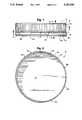
- FIG. 7is a horizontal cross-sectional view of the closure of the invention taken along line 7--7 of FIG. 6 and in the direction indicated generally illustrating the flexible contact of the engagement member with the container neck.
- the closure 10is of a one-piece design and includes an annular end cap 12 having a first closed end 14, a second opposite open end 16 and an annular side wall 18 interconnecting the first and second ends 14 and 16.
- a tamper indicating band 20 frangiblyis connected about the second open end 16 of the end cap 12 by a plurality of severable strap members 22.
- a plurality of severable strap members 22Preferably, eight straps 22 are utilized, one each positioned in predetermined locations about the periphery of the closure 10. It is to be understood that the number of straps 22 as well as the particular frangible connection between the tamper band 20 and end cap 12 can vary.
- the closure 10is utilized to threadingly engage a neck portion 24 of a container 26 and to seal the mouth (not illustrated) of the container 26 against leakage of material contained therein.
- a flexible engagement portion or flange 28integrally is formed with the tamper band 20 to grip a substantially cylindrical or rectilinear portion 30 of the neck 24 during mounting and removal of the closure 10 from the container 26.
- the engagement portion 28restricts the tamper band 20 from axial movement to enable severing of the straps 22 and keeps the tamper band 20 on the container neck 24 after severing of the straps 22 and removal of the end cap 12, without any flange on the neck portion 24, to provide evidence of tampering with the container 26 and/or closure 10.
- closure 10 and container 26are formed from plastic, but the particular material, size and shape of the closure 10 and container 26 can vary. Additionally, although the closure 10 is depicted as being threadingly engaged with the container 26, it is to be understood that the particular engagement between the closure 10 and container 26 also can vary so long as the closure 10 functions as described herein.
- an exterior surface of the neck 24 of the container 26includes a plurality of threads 32.
- the threads 32are designed for complementary threading engagement with threads 34 formed on an interior surface 36 of the side wall 18 of the end cap 120.
- FIG. 3illustrates the general shape of the closure 10 before being assembled to the container 26.
- the tamper band 20is connected to the second open end 16 of the end cap 12 by the severable straps 22, only one of which is illustrated.
- the flexible engagement portion or flange 28substantially is annular in shape and includes a first proximal end 36, integrally formed with a bottom surface 38 of the tamper band 20, and a second distal end 40, extending downwardly away from the tamper band 20 at a slight angle toward the interior of the end cap 12, which is to the left with respect to FIG. 3.
- the first proximal end 36preferably is formed with relieved annular portions 42, one each on either side of the engagement portion 28.
- the relieved portions 42thus provide somewhat of a hinge action to the first proximal end 36 of the engagement portion 28.
- FIG. 4illustrates, during fitting or mounting of the closure 10 onto the neck 24 of the container 26, the engagement portion 28 of the tamper band 22 is flexed upward by the container mouth and neck portion 24 and rotates about the first proximal end 36 toward the tamper band 22 to the position illustrated.
- an outside edge 44 of the distal end 40 of the engagement portion 28engages the cylindrical rectilinear portion 30 of the neck 24 and provides engagement along a line or "line contact" as opposed to contact over a surface area.
- an inside surface 46 of the tamper band 22includes a plurality of ribs 48 formed therewith.
- ribs 48are utilized, one each at a predetermined position about the inside surface 46 but the number, shape and positioning of the ribs 48 can vary.
- the ribs 48substantially extend across the width of the tamper band 22 and include an engagement corner 50 which contacts a portion of the engagement portion 28 proximate the first proximal end 36. The ribs 48 therefore limit the upward or inward flexing of the engagement portion 28 which in turn increases the resilient and compressive forces exerted on the neck 24.
- the engagement portion 28is provided with a wave-like, serpentine or pleated shape as FIG. 7 illustrates. This wave-like configuration strengthens the tamper band 22 and engagement portion 28, provides increased engagement proximate the ribs 48 and assists in filling in the area between the closure 10 and the container 26. If desired, the engagement portion 28 can be pre-formed with the wave-like or serpentine shape rather than having the ribs 48 provide such a shape.
- closure 10To install the closure 10 to the neck 24 of the container 26, the closure 10 is provided as illustrated in FIGS. 1 and 3 with the engagement portion 28 of the tamper band 22 extending downward or outward. The closure 10 then axially is aligned with the open mouth of the container 26 and forced downward thereon, with or without twisting or screwing of the closure 10, until the closure 10 is seated on the neck 24 in the position illustrated in FIGS. 4 and 6.
- the end cap 12is unscrewed while the tamper band 22 remains axially and/or rotationally secured to the rectilinear portion 30 thereby severing the straps 22 as the end cap 12 moves axially away due to the action of the screw threads 32 and 34.
- the end cap 12then can be removed from the container 26 with the tamper band 20 remaining about the neck 24 to provide evidence of tampering.
- the engagement portion 28can include thread portions 51 formed thereabout.
- the thread portions 51are positioned at intervals about the engagement portion 28 and approximate the dimensions of the container threads 32 for alignment therewith.
- the engagement portion 28 and ribs 48provide sufficient gripping of the rectilinear portion 30 after being assembled to the container 26 to enable the desired severing of the straps 22 without the need for any additional flange On the neck 24.
- the rectilinear portion 30 of the neck 24can be tapered slightly outward toward the open mouth of the container (not illustrated).
- the neck 24can be formed to include an annular bead 52 thereabout.
- the bead 52substantially is rounded and does not provide a discrete surface against which the engagement portion 28 axially would abut to provide any severing of the straps 22.
- the bead 52rather, provides a slight outward deflection of the engagement portion 28 toward the tamper band 20. The slight outward deflection in turn enhances the gripping power of the engagement portion 28 against the rounded surface of the bead 52 since the engagement portion 28 is further leveraged between the bead 52 and the ribs 48.
Landscapes
- Engineering & Computer Science (AREA)
- Mechanical Engineering (AREA)
- Closures For Containers (AREA)
- Cartons (AREA)
- Slot Machines And Peripheral Devices (AREA)
- Bag Frames (AREA)
Abstract
Description
Claims (8)
Priority Applications (4)
| Application Number | Priority Date | Filing Date | Title |
|---|---|---|---|
| US07/980,623US5282540A (en) | 1992-11-23 | 1992-11-23 | Tamper band with flexible engagement member |
| CA002148804ACA2148804C (en) | 1992-11-23 | 1993-10-25 | Tamper band with flexible engagement member |
| AU54108/94AAU668258B2 (en) | 1992-11-23 | 1993-10-25 | Tamper band with flexible engagement member |
| PCT/US1993/010206WO1994012400A1 (en) | 1992-11-23 | 1993-10-25 | Tamper band with flexible engagement member |
Applications Claiming Priority (1)
| Application Number | Priority Date | Filing Date | Title |
|---|---|---|---|
| US07/980,623US5282540A (en) | 1992-11-23 | 1992-11-23 | Tamper band with flexible engagement member |
Publications (1)
| Publication Number | Publication Date |
|---|---|
| US5282540Atrue US5282540A (en) | 1994-02-01 |
Family
ID=25527715
Family Applications (1)
| Application Number | Title | Priority Date | Filing Date |
|---|---|---|---|
| US07/980,623Expired - LifetimeUS5282540A (en) | 1992-11-23 | 1992-11-23 | Tamper band with flexible engagement member |
Country Status (4)
| Country | Link |
|---|---|
| US (1) | US5282540A (en) |
| AU (1) | AU668258B2 (en) |
| CA (1) | CA2148804C (en) |
| WO (1) | WO1994012400A1 (en) |
Cited By (34)
| Publication number | Priority date | Publication date | Assignee | Title |
|---|---|---|---|---|
| US5407091A (en)* | 1993-04-14 | 1995-04-18 | Wallis; Martin | Rainwater storage tanks |
| US5462186A (en)* | 1994-08-02 | 1995-10-31 | The Coca Cola Company | Cam follower closure on container with cam track finish |
| US5570798A (en)* | 1994-05-17 | 1996-11-05 | Mikasa Industry Co., Inc. | Container opening/closing device |
| US5727705A (en)* | 1996-11-22 | 1998-03-17 | Crown Cork & Seal Technologies Corporation | Closure cap for closure of a container mouth |
| US5755347A (en)* | 1989-07-27 | 1998-05-26 | Owens-Illinois Closure Inc. | Tamper indicating package |
| US6119883A (en)* | 1998-12-07 | 2000-09-19 | Owens-Illinois Closure Inc. | Tamper-indicating closure and method of manufacture |
| US6152316A (en)* | 1999-05-17 | 2000-11-28 | Owens-Illinois Closure Inc. | Tamper-indicating closure and method of manufacture |
| US6371317B1 (en) | 1998-08-07 | 2002-04-16 | Kerr Group, Inc. | Tamper indicating closure with foldable tab |
| US6382443B1 (en) | 1999-04-28 | 2002-05-07 | Owens-Illinois Closure Inc. | Tamper-indicating closure with lugs on a stop flange for spacing the flange from the finish of a container |
| US6491175B1 (en) | 2000-06-28 | 2002-12-10 | Saad Taha | Single piece closure for a pressurized container |
| US20030000907A1 (en)* | 1997-09-19 | 2003-01-02 | Gregory Kevorkian | Vented beverage container |
| US6644487B2 (en) | 2001-08-17 | 2003-11-11 | Seaquist Closures Foreign, Inc. | Tamper-evident closure with break-off piece retention |
| US20040007553A1 (en)* | 1997-09-19 | 2004-01-15 | Smolko Daniel D. | Pervaporatively cooled containers |
| US6691901B2 (en) | 2001-12-14 | 2004-02-17 | Gateway Plastics, Inc. | Closure for a container |
| US20040069738A1 (en)* | 2002-08-07 | 2004-04-15 | Orth Kevin William | Reduced application energy closure |
| US20040173556A1 (en)* | 1997-09-19 | 2004-09-09 | Smolko Daniel D. | Vented closures for containers |
| US20050189312A1 (en)* | 1998-08-07 | 2005-09-01 | Bixler Frederick L. | Tamper indicating closure with foldable tab |
| USD509426S1 (en) | 1997-10-28 | 2005-09-13 | Gateway Plastics, Inc. | Integrally-formed closure for a container |
| USD513452S1 (en) | 2002-09-27 | 2006-01-10 | Gateway Plastics, Inc. | Closure for a container |
| USD532298S1 (en) | 2004-11-20 | 2006-11-21 | Gateway Plastics, Inc. | Closure for a container |
| US20060261096A1 (en)* | 2003-10-10 | 2006-11-23 | Alei Phillip E | Liquid dispensing valve assembly having a unitarily formed base and a vacuum release feature |
| USD532691S1 (en) | 2004-11-20 | 2006-11-28 | Gateway Plastics, Inc. | Closure for a container |
| USD533452S1 (en) | 2004-11-20 | 2006-12-12 | Gateway Plastics, Inc. | Closure for a container |
| US20070068977A1 (en)* | 2002-12-21 | 2007-03-29 | Gateway Plastics, Inc. | Closure for a container |
| US20070102389A1 (en)* | 2005-11-08 | 2007-05-10 | Seaquist Closures Foreign, Inc. | Tamper-evident closure |
| US20070102390A1 (en)* | 2005-11-08 | 2007-05-10 | Seaquist Closures Foreign, Inc. | Closure with deformed wall retention of lid hinge shaft |
| US20070228079A1 (en)* | 2006-02-16 | 2007-10-04 | Gateway Plastics, Inc. | Closure for a container |
| US20070246485A1 (en)* | 2005-12-20 | 2007-10-25 | Shelby Mathew | Apparatus for controlled initiation of fluid-flow from an inverted container |
| US20080164235A1 (en)* | 2007-01-05 | 2008-07-10 | Phoenix Closures, Inc. | Tamper-evident closure and container combination |
| US20080257918A1 (en)* | 2004-09-05 | 2008-10-23 | Gateway Plastics Inc. | Closure for a Container |
| US20090139954A1 (en)* | 2007-12-04 | 2009-06-04 | Len Ekkert | Closure With Improved Tamper-Evident Band |
| USD596029S1 (en) | 2006-06-20 | 2009-07-14 | Gateway Plastics, Inc. | Closure for a container |
| US20100122254A1 (en)* | 2008-11-11 | 2010-05-13 | Cray Inc. | Batch and application scheduler interface layer in a multiprocessor computing environment |
| US11059633B2 (en) | 2019-10-31 | 2021-07-13 | Cheer Pack North America | Flip-top closure for container |
Citations (11)
| Publication number | Priority date | Publication date | Assignee | Title |
|---|---|---|---|---|
| US4470513A (en)* | 1982-09-23 | 1984-09-11 | Ethyl Molded Products Company | Tamper-indicating closure |
| US4478343A (en)* | 1982-09-23 | 1984-10-23 | Ethyl Molded Products Company | Tamper-indicating closure |
| US4550844A (en)* | 1984-06-22 | 1985-11-05 | Owens-Illinois, Inc. | Tamper resistant closure with tear-off band |
| US4700859A (en)* | 1986-08-11 | 1987-10-20 | Owens-Illinois Closure Inc. | Tamper indicating closure |
| US4721218A (en)* | 1987-02-17 | 1988-01-26 | Owens-Illinois Closure Inc. | Tamper indicating package |
| US4753360A (en)* | 1986-09-16 | 1988-06-28 | National Plastics Limited | Container closure |
| US4784280A (en)* | 1987-02-26 | 1988-11-15 | Crown Cork Ag | Sealing cap with a safety band |
| US4801031A (en)* | 1987-05-28 | 1989-01-31 | Owens-Illinois Closure Inc. | Tamper-indicating closures and packages |
| USRE33265E (en)* | 1985-04-29 | 1990-07-17 | Owens-Illinois Closure Inc. | Tamper-indicating closure, container and combination thereof |
| US5004112A (en)* | 1990-04-10 | 1991-04-02 | H-C Industries, Inc. | Tamper-indicating plastic closure |
| US5096079A (en)* | 1989-12-08 | 1992-03-17 | Astra Plastique | Screw-on stopper cap, having a tamper-proof band |
Family Cites Families (4)
| Publication number | Priority date | Publication date | Assignee | Title |
|---|---|---|---|---|
| US4801030A (en)* | 1987-05-28 | 1989-01-31 | Owens-Illinois Closure Inc. | Tamper-indicating closure and package |
| US5080246A (en)* | 1989-09-01 | 1992-01-14 | Anchor Hocking Packaging Company | Closure having a spring open tamper evidencing band |
| US5058755A (en)* | 1989-09-01 | 1991-10-22 | Anchor Hocking Packaging Company | Tamper indicating closure having retaining hoop with relief windows |
| ATE127756T1 (en)* | 1990-08-20 | 1995-09-15 | Anchor Hocking Packaging | ORIGINALITY CAP WITH RELIEF WINDOWS IN THE RETAINING RING. |
- 1992
- 1992-11-23USUS07/980,623patent/US5282540A/ennot_activeExpired - Lifetime
- 1993
- 1993-10-25CACA002148804Apatent/CA2148804C/ennot_activeExpired - Fee Related
- 1993-10-25WOPCT/US1993/010206patent/WO1994012400A1/enactiveApplication Filing
- 1993-10-25AUAU54108/94Apatent/AU668258B2/ennot_activeCeased
Patent Citations (11)
| Publication number | Priority date | Publication date | Assignee | Title |
|---|---|---|---|---|
| US4470513A (en)* | 1982-09-23 | 1984-09-11 | Ethyl Molded Products Company | Tamper-indicating closure |
| US4478343A (en)* | 1982-09-23 | 1984-10-23 | Ethyl Molded Products Company | Tamper-indicating closure |
| US4550844A (en)* | 1984-06-22 | 1985-11-05 | Owens-Illinois, Inc. | Tamper resistant closure with tear-off band |
| USRE33265E (en)* | 1985-04-29 | 1990-07-17 | Owens-Illinois Closure Inc. | Tamper-indicating closure, container and combination thereof |
| US4700859A (en)* | 1986-08-11 | 1987-10-20 | Owens-Illinois Closure Inc. | Tamper indicating closure |
| US4753360A (en)* | 1986-09-16 | 1988-06-28 | National Plastics Limited | Container closure |
| US4721218A (en)* | 1987-02-17 | 1988-01-26 | Owens-Illinois Closure Inc. | Tamper indicating package |
| US4784280A (en)* | 1987-02-26 | 1988-11-15 | Crown Cork Ag | Sealing cap with a safety band |
| US4801031A (en)* | 1987-05-28 | 1989-01-31 | Owens-Illinois Closure Inc. | Tamper-indicating closures and packages |
| US5096079A (en)* | 1989-12-08 | 1992-03-17 | Astra Plastique | Screw-on stopper cap, having a tamper-proof band |
| US5004112A (en)* | 1990-04-10 | 1991-04-02 | H-C Industries, Inc. | Tamper-indicating plastic closure |
Cited By (53)
| Publication number | Priority date | Publication date | Assignee | Title |
|---|---|---|---|---|
| US5755347A (en)* | 1989-07-27 | 1998-05-26 | Owens-Illinois Closure Inc. | Tamper indicating package |
| US5407091A (en)* | 1993-04-14 | 1995-04-18 | Wallis; Martin | Rainwater storage tanks |
| US5570798A (en)* | 1994-05-17 | 1996-11-05 | Mikasa Industry Co., Inc. | Container opening/closing device |
| CN1042019C (en)* | 1994-05-17 | 1999-02-10 | 三笠产业株式会社 | Opening and closing device of container |
| US5462186A (en)* | 1994-08-02 | 1995-10-31 | The Coca Cola Company | Cam follower closure on container with cam track finish |
| US5727705A (en)* | 1996-11-22 | 1998-03-17 | Crown Cork & Seal Technologies Corporation | Closure cap for closure of a container mouth |
| WO1998022361A1 (en)* | 1996-11-22 | 1998-05-28 | Crown Cork & Seal Technologies Corporation | Closure cap for closure of a container mouth |
| US20050263480A1 (en)* | 1997-09-19 | 2005-12-01 | Advanced Porous Technologies, Llc | Vented closures for containers |
| US7107783B2 (en) | 1997-09-19 | 2006-09-19 | Advanced Porcus Technologies, Llc | Self-cooling containers for liquids |
| US20030000907A1 (en)* | 1997-09-19 | 2003-01-02 | Gregory Kevorkian | Vented beverage container |
| US20050263479A1 (en)* | 1997-09-19 | 2005-12-01 | Advanced Porous Technologies, Llc | Vented closures for containers |
| US20040173556A1 (en)* | 1997-09-19 | 2004-09-09 | Smolko Daniel D. | Vented closures for containers |
| US20040007553A1 (en)* | 1997-09-19 | 2004-01-15 | Smolko Daniel D. | Pervaporatively cooled containers |
| USD530610S1 (en) | 1997-10-28 | 2006-10-24 | Gateway Plastic, Inc. | Integrally-formed closure for a container |
| USD509426S1 (en) | 1997-10-28 | 2005-09-13 | Gateway Plastics, Inc. | Integrally-formed closure for a container |
| US7344039B2 (en) | 1998-08-07 | 2008-03-18 | Berry Plastics Corporation | Tamper indicating band having foldable tabs including tab extensions, tamper indicating closure including such tamper indicating band, and tamper indicating closure including such tamper indicating band and container |
| US6371317B1 (en) | 1998-08-07 | 2002-04-16 | Kerr Group, Inc. | Tamper indicating closure with foldable tab |
| US20050189312A1 (en)* | 1998-08-07 | 2005-09-01 | Bixler Frederick L. | Tamper indicating closure with foldable tab |
| US6673298B2 (en) | 1998-08-07 | 2004-01-06 | Kerr Group, Inc. | Tamper indicating closure with foldable tab |
| US6119883A (en)* | 1998-12-07 | 2000-09-19 | Owens-Illinois Closure Inc. | Tamper-indicating closure and method of manufacture |
| US6622460B2 (en) | 1999-04-28 | 2003-09-23 | Owens-Illinois Closure Inc. | Tamper-indicating closure with lugs on a stop flange for spacing the flange from the finish of a container |
| US6382443B1 (en) | 1999-04-28 | 2002-05-07 | Owens-Illinois Closure Inc. | Tamper-indicating closure with lugs on a stop flange for spacing the flange from the finish of a container |
| US6968966B2 (en) | 1999-04-28 | 2005-11-29 | Owens Illinois Closure Inc. | Tamper-indicating closure with lugs on a stop flange for spacing the flange from the finish of a container |
| US20030192854A1 (en)* | 1999-04-28 | 2003-10-16 | Gregory James L. | Tamper-indicating closure with lugs on a stop flange for spacing the flange from the finish of a container |
| US6152316A (en)* | 1999-05-17 | 2000-11-28 | Owens-Illinois Closure Inc. | Tamper-indicating closure and method of manufacture |
| US6491175B1 (en) | 2000-06-28 | 2002-12-10 | Saad Taha | Single piece closure for a pressurized container |
| US6640988B2 (en) | 2000-06-28 | 2003-11-04 | Saad Taha | Container closure |
| US6626310B2 (en) | 2000-06-28 | 2003-09-30 | Saad Taha | Closure with gas barrier seal for a pressurized container |
| US7044317B2 (en) | 2001-08-17 | 2006-05-16 | Seaquist Closures Foreign, Inc. | Tamper-evident closure with break-off piece retention |
| US6644487B2 (en) | 2001-08-17 | 2003-11-11 | Seaquist Closures Foreign, Inc. | Tamper-evident closure with break-off piece retention |
| US6691901B2 (en) | 2001-12-14 | 2004-02-17 | Gateway Plastics, Inc. | Closure for a container |
| US20040069738A1 (en)* | 2002-08-07 | 2004-04-15 | Orth Kevin William | Reduced application energy closure |
| USD513452S1 (en) | 2002-09-27 | 2006-01-10 | Gateway Plastics, Inc. | Closure for a container |
| US20070068977A1 (en)* | 2002-12-21 | 2007-03-29 | Gateway Plastics, Inc. | Closure for a container |
| US20060261096A1 (en)* | 2003-10-10 | 2006-11-23 | Alei Phillip E | Liquid dispensing valve assembly having a unitarily formed base and a vacuum release feature |
| US8066158B2 (en) | 2004-09-05 | 2011-11-29 | Gateway Plastics, Inc. | Closure for a container |
| US20080257918A1 (en)* | 2004-09-05 | 2008-10-23 | Gateway Plastics Inc. | Closure for a Container |
| USD582274S1 (en)* | 2004-11-20 | 2008-12-09 | Gateway Plastics, Inc. | Closure for a container |
| USD533452S1 (en) | 2004-11-20 | 2006-12-12 | Gateway Plastics, Inc. | Closure for a container |
| USD532298S1 (en) | 2004-11-20 | 2006-11-21 | Gateway Plastics, Inc. | Closure for a container |
| USD532691S1 (en) | 2004-11-20 | 2006-11-28 | Gateway Plastics, Inc. | Closure for a container |
| USD582273S1 (en)* | 2004-11-20 | 2008-12-09 | Gateway Plastics, Inc. | Closure for a container |
| US20070102389A1 (en)* | 2005-11-08 | 2007-05-10 | Seaquist Closures Foreign, Inc. | Tamper-evident closure |
| US20070102390A1 (en)* | 2005-11-08 | 2007-05-10 | Seaquist Closures Foreign, Inc. | Closure with deformed wall retention of lid hinge shaft |
| US20070246485A1 (en)* | 2005-12-20 | 2007-10-25 | Shelby Mathew | Apparatus for controlled initiation of fluid-flow from an inverted container |
| US7621425B2 (en) | 2005-12-20 | 2009-11-24 | Genx Innovations, Llc | Apparatus for controlled initiation of fluid-flow from an inverted container |
| US20070228079A1 (en)* | 2006-02-16 | 2007-10-04 | Gateway Plastics, Inc. | Closure for a container |
| USD596029S1 (en) | 2006-06-20 | 2009-07-14 | Gateway Plastics, Inc. | Closure for a container |
| US20080164235A1 (en)* | 2007-01-05 | 2008-07-10 | Phoenix Closures, Inc. | Tamper-evident closure and container combination |
| US8353413B2 (en) | 2007-01-05 | 2013-01-15 | Phoenix Closures, Inc. | Tamper-evident closure and container combination |
| US20090139954A1 (en)* | 2007-12-04 | 2009-06-04 | Len Ekkert | Closure With Improved Tamper-Evident Band |
| US20100122254A1 (en)* | 2008-11-11 | 2010-05-13 | Cray Inc. | Batch and application scheduler interface layer in a multiprocessor computing environment |
| US11059633B2 (en) | 2019-10-31 | 2021-07-13 | Cheer Pack North America | Flip-top closure for container |
Also Published As
| Publication number | Publication date |
|---|---|
| AU5410894A (en) | 1994-06-22 |
| CA2148804C (en) | 1998-08-04 |
| AU668258B2 (en) | 1996-04-26 |
| CA2148804A1 (en) | 1994-06-09 |
| WO1994012400A1 (en) | 1994-06-09 |
Similar Documents
| Publication | Publication Date | Title |
|---|---|---|
| US5282540A (en) | Tamper band with flexible engagement member | |
| US5215204A (en) | Tamper evident closure with hinged band | |
| CA2293535C (en) | Sports beverage snap closure | |
| US7988004B1 (en) | Dispensing closure with tamper evident device | |
| US4176755A (en) | Resealable pour bottle with severing ring | |
| CA1227457A (en) | Safety closure | |
| RU2139230C1 (en) | Cap with opening indicating strip | |
| US4709823A (en) | Tamper evident bottle or package closure | |
| US5680965A (en) | Tamper evident container closure | |
| RU2387589C2 (en) | Packaging product | |
| US4948003A (en) | Container and closure with internal tamper indication | |
| EP0770560B1 (en) | Tamper-evident, child resistant closure | |
| EP0163470A2 (en) | A tamper evident closure | |
| US20080173611A1 (en) | Tamper evident band with hook | |
| US20050269373A1 (en) | Cover for dispensing closure with pressure actuated valve | |
| US11858710B2 (en) | Spouted pouch provided with a closure device | |
| CA1285525C (en) | Safety closure and container package | |
| US6116442A (en) | Tamper indicating closure | |
| CA1309379C (en) | Tamper-evident cap construction | |
| HUP0003431A2 (en) | Single-piece plastic lid | |
| JPS6382957A (en) | Cover for vessel | |
| US6431404B1 (en) | Tamper evident plastic closure | |
| EP0323812A2 (en) | Improvement in the composite closure caps with evidencing of the tampering | |
| JP2001058658A (en) | Plastic cap | |
| US6394294B1 (en) | Closure having torque-reducing feature |
Legal Events
| Date | Code | Title | Description |
|---|---|---|---|
| AS | Assignment | Owner name:CREATIVE PACKAGING CORP., ILLINOIS Free format text:ASSIGNMENT OF ASSIGNORS INTEREST.;ASSIGNOR:BECK, JAMES M.;REEL/FRAME:006342/0866 Effective date:19921120 | |
| STCF | Information on status: patent grant | Free format text:PATENTED CASE | |
| CC | Certificate of correction | ||
| FPAY | Fee payment | Year of fee payment:4 | |
| AS | Assignment | Owner name:BANK OF AMERICA, N.A., TEXAS Free format text:ASSIGNMENT AND SECURITY AGREEMENT;ASSIGNORS:LLS CORP.;COURTESY CORPORATION;CREATIVE PACKAGING CORP.;AND OTHERS;REEL/FRAME:010180/0262 Effective date:19990730 | |
| FEPP | Fee payment procedure | Free format text:PAT HLDR NO LONGER CLAIMS SMALL ENT STAT AS SMALL BUSINESS (ORIGINAL EVENT CODE: LSM2); ENTITY STATUS OF PATENT OWNER: LARGE ENTITY | |
| FPAY | Fee payment | Year of fee payment:8 | |
| AS | Assignment | Owner name:BANK OF AMERICA, N.A., TEXAS Free format text:SECURITY AGREEMENT;ASSIGNOR:COURTESY CORPORATION; CREATIVE PACKAGING CORP.;REEL/FRAME:012539/0589 Effective date:20020116 | |
| AS | Assignment | Owner name:CREATIVE PACKAGING CORP., ILLINOIS Free format text:RELEASE OF SECURITY INTERESTS;ASSIGNOR:BANK OF AMERICA, N.A.;REEL/FRAME:013467/0957 Effective date:20021024 | |
| AS | Assignment | Owner name:WACHOVIA BANK, NATIONAL ASSOCIATION, NORTH CAROLIN Free format text:SECURITY INTEREST;ASSIGNOR:CREATIVE PACKAGING CORP.;REEL/FRAME:013484/0041 Effective date:20021024 | |
| AS | Assignment | Owner name:CREATIVE PACKAGING CORP., ILLINOIS Free format text:RELEASE OF SECURITY INTEREST;ASSIGNOR:WACHOVIA BANK, NATIONAL ASSOCIATION;REEL/FRAME:015065/0799 Effective date:20040319 Owner name:WACHOVIA BANK, NATIONAL ASSOCIATEION, NORTH CAROLI Free format text:SECURITY AGREEMENT;ASSIGNOR:CREATIVE PACKAGING CORP.;REEL/FRAME:015065/0804 Effective date:20040322 | |
| FEPP | Fee payment procedure | Free format text:PAYOR NUMBER ASSIGNED (ORIGINAL EVENT CODE: ASPN); ENTITY STATUS OF PATENT OWNER: LARGE ENTITY | |
| FPAY | Fee payment | Year of fee payment:12 | |
| AS | Assignment | Owner name:REXAM CLOSURES AND CONTAINERS INC., NORTH CAROLINA Free format text:ASSIGNMENT OF ASSIGNORS INTEREST;ASSIGNOR:CREATIVE PACKAGING CORPORATION;REEL/FRAME:028548/0802 Effective date:20110815 | |
| AS | Assignment | Owner name:REXAM CLOSURES LLC, NORTH CAROLINA Free format text:ASSIGNMENT OF ASSIGNORS INTEREST;ASSIGNOR:REXAM CLOSURES AND CONTAINERS, INC.;REEL/FRAME:028680/0204 Effective date:20110815 | |
| AS | Assignment | Owner name:BERRY PLASTICS CORPORATION, INDIANA Free format text:ASSIGNMENT OF ASSIGNORS INTEREST;ASSIGNOR:REXAM CLOSURES LLC;REEL/FRAME:028715/0215 Effective date:20120529 |