US5282478A - Guidewire extension system with coil connectors - Google Patents
Guidewire extension system with coil connectorsDownload PDFInfo
- Publication number
- US5282478A US5282478AUS07/748,301US74830191AUS5282478AUS 5282478 AUS5282478 AUS 5282478AUS 74830191 AUS74830191 AUS 74830191AUS 5282478 AUS5282478 AUS 5282478A
- Authority
- US
- United States
- Prior art keywords
- guidewire
- helical coil
- coil
- extension wire
- turns
- Prior art date
- Legal status (The legal status is an assumption and is not a legal conclusion. Google has not performed a legal analysis and makes no representation as to the accuracy of the status listed.)
- Expired - Lifetime
Links
Images


Classifications
- A—HUMAN NECESSITIES
- A61—MEDICAL OR VETERINARY SCIENCE; HYGIENE
- A61M—DEVICES FOR INTRODUCING MEDIA INTO, OR ONTO, THE BODY; DEVICES FOR TRANSDUCING BODY MEDIA OR FOR TAKING MEDIA FROM THE BODY; DEVICES FOR PRODUCING OR ENDING SLEEP OR STUPOR
- A61M25/00—Catheters; Hollow probes
- A61M25/01—Introducing, guiding, advancing, emplacing or holding catheters
- A61M25/09—Guide wires
- A61M25/0905—Guide wires extendable, e.g. mechanisms for extension
- Y—GENERAL TAGGING OF NEW TECHNOLOGICAL DEVELOPMENTS; GENERAL TAGGING OF CROSS-SECTIONAL TECHNOLOGIES SPANNING OVER SEVERAL SECTIONS OF THE IPC; TECHNICAL SUBJECTS COVERED BY FORMER USPC CROSS-REFERENCE ART COLLECTIONS [XRACs] AND DIGESTS
- Y10—TECHNICAL SUBJECTS COVERED BY FORMER USPC
- Y10T—TECHNICAL SUBJECTS COVERED BY FORMER US CLASSIFICATION
- Y10T403/00—Joints and connections
- Y10T403/45—Flexibly connected rigid members
- Y10T403/459—Helical spring type coupling
Definitions
- the present inventiongenerally relates guidewires used in vascular surgery and procedures, and specifically to angioplasty and embolectomy guidewires.
- Guidewiresare used in various surgical catheter procedures to steer a catheter to a desired location in the patient's vascular system.
- the guidewiresare inserted and steered through the patient's vascular system to the desired site.
- the catheteris typically positioned over a portion of the guidewire during this initial placement, and then pushed along the guidewire until properly positioned at the desired site.
- Standard guidewiresare typically longer than the catheter to allow for independent movement of the catheter and the wire. Examples of suitable guidewires are illustrated in U.S. Pat. No. 4,538,622, issued to Samson et al on Sep. 3, 1985; U.S. Pat. No. 4,719,924, issued to Crittenden et al on Jan. 19, 1988; U.S. Pat. No. 4,934,380, issued to de Toledo on Jun. 19, 1990 and European Patent Application Number 89304257.2, published on Dec. 20, 1989.
- the guidewireis steered to the vascular blockage.
- the steering of the guidewireis facilitated by a video X-ray device allowing the surgeon to visually observe the movement of the guidewire.
- the guidewireusually includes a radiopaque marker at its distal end to provide a reference for the surgeon. The surgeon positions the radiopaque marker adjacent the blockage, and then slides a balloon angioplasty catheter over the wire to the blockage.
- the balloonis expanded to open the blockage and then is removed along with the guidewire. However, sometimes the balloon breaks, or a larger sized balloon is required to fully open the blockage. In either situation the balloon catheter must be removed, and a replacement catheter is slid over the guidewire.
- the surgeonremoves the catheter over the guidewire, retaining the wire in the patient.
- the guidewiremust be sufficiently long enough to allow the surgeon to grip a portion of the wire as the catheter is being withdrawn. This requires the guidewire be long enough to provide an external portion longer than the catheter.
- a wire this longis difficult to steer, and as a result, guidewires are usually only slightly longer than the typical balloon catheter, e.g. 20-50 centimeters.
- a more recent developmentinvolves coupling a length of a second wire to the exposed guidewire end.
- the second wire lengthshould be sufficient to allow the catheter to be withdrawn while retaining the placement of the guidewire in the patient.
- Various approacheshave been suggested for affecting this coupling action.
- United Kingdom Patent Application Number 8615949published Apr. 1, 1987, corresponding to U.S. Pat. No. 4,917,103, issued to Gamble et al on Apr. 17, 1990, discloses a guidewire extension wire with a tubular connector fitted to the end of either the exposed guidewire or the extension wire.
- the other wireis formed with a reduced diameter end which slips into the tubular connector.
- Gamble et aldiscloses crimping the tubular connector.
- the basic disadvantage to this approachis that the tubular connector does not sufficiently grip the reduced diameter end of the wire unless crimped to prevent dislodging of the guidewire from the extension during the catheter exchange.
- U.S. Pat. No. 4,846,193 to William S. Tremulis et al.describes an extendable guidewire which permits the introduction and exchange of catheters.
- the guidewire of the '193 Tremulis patenthas a telescopically mounted inner shaft or wire having axially extended and retracted positions.
- a disadvantage with the Kraus et al deviceis the fabrication of the female and male threaded sections.
- the actual size of the connectorsis relatively small, i.e. less than 2.3 millimeters. It is difficult to fabricate female and male threaded portions of this size. If the size of the connectors is increased over the diameter of the guidewire and extension wire, the disadvantages discussed above for the DOCTM and LINXTM Guide Wire Extension systems apply.
- the present inventionovercomes the above discussed disadvantages by providing a guidewire extension system including a guidewire with proximal and distal ends, and an extension wire with opposing ends.
- First and second flexible connectorsare mounted to one of the extension wire ends and the guidewire proximal end.
- the connectorsare interlocking helical coils which are connected by rotating one with respect to the other.
- the preferred embodiment of the extendable guidewire system of the inventionincludes a guidewire section and an extension wire section.
- the guidewire sectionis designed for placement into a vascular system and has proximal and distal ends.
- the guidewire section proximal endincludes a helical coil with the most proximally located helical coil turns spatially separated to form gaps between adjacent turns.
- the extension wire sectionhas a diameter substantially equivalent to that of the guidewire section, and includes at one of its opposing ends a helical coil formed with gaps between adjacent turns.
- the gaps of the two helical coilsare compatibly spaced and adapted to receive the other helical coil turns when the guidewire proximal end helical coil and extension end helical coil are screwed together.
- a stem, pilot, or guide pinextends from one or the other of the helical coils.
- the guide pinis adapted to be received inside the other of the helical coils to enhance ease of interlock.
- a cooperating tubular sleeve, socket extension or coupling tubemay be included within one or the other of the helical coils. The socket extension would cooperate with and receive the guide pin located within the other coil to enhance the ease of coil interlock and connector rigidity.
- the cooperating helical coilsare provided with means to enhance or to identify their state of interlock.
- an affirmative lock or snap meansmay be provided on cooperating segments of the respective coils so that an intended state of interlock may be identified.
- diminishing or increasing coil separation distancemay be utilized to increase or enhance the interaction between coils. Rotation or winding of the coils into each other becomes increasingly difficult as the intended coupling state is approached.
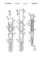
- FIG. 1is a prospective view of a guidewire and an extension wire in accordance with the invention, with the extension wire fitted in a coiled tubular holder;
- FIG. 1Ais a partially sectional enlarged view of the guidewire and extension wire of FIG. 1 at 1A;
- FIGS. 2A and 2Bare close-up views of the helical coil connectors before and after coupling
- FIG. 3A-Care side views of various embodiments of the invention incorporating rotating joints contiguous the helical coil
- FIG. 4is a side view of a further embodiment of the helical coil connectors respectively affixed to the ends of the guidewire and the extension wire;
- FIGS. 5A and 5Bare side view of still further embodiments of the helical coil connectors of the invention.
- Guidewiresgenerally include a main core, preferably composed of a solid wire.
- a helical coil springis mounted about the distal portion of this core wire.
- the distal ends of the core wire and helical coil springsmay be connected by brazing, adhesive bonding, mechanical interaction, or restriction fit.
- the proximal portion of the guidewireis usually formed by only the core wire. This proximal portion may be coated with a polymeric material, e.g. polytetrafluoroethylene, to enhance the lubricity of the guidewire.
- typical guidewire dimensionsare from about 100 centimeters (cm) to 400 cm long and from about 0.008 inches to about 0.100 inches in diameter.
- a guidewire employed with the present inventionis not critical. Many different types of guidewire configuration are suitable. Examples of such guidewires are found in U.S. Pat. No. 4,538,622, issued to Samson et al on Sep. 3, 1985; U.S. Pat. No. 4,719,924, issued to Crittenden et al on Jan. 19, 1988; U.S. Pat. No. 4,934,380, issued to de Toledo on Jun. 19, 1990 and European Patent Application Number 89304257.2, published on Dec. 20, 1989.
- the main modification to the described guidewire constructionis the provision of a helical coil connector at the very proximal end of the guidewire.
- This helical coilis coupled with a similarly configured helical coil arranged at one end of an extension wire.
- each helical coilis at least partially loosely wound or stretched to provide gaps between adjacent coil turns. The dimension of these gaps is sufficient to allow the two coils to be easily twisted together, while maintaining a sufficiently positive engagement or interaction therebetween.
- the positive interactionmay be restrictive or frictional, or simply cooperative.
- connection between the two coilshas many advantages over the commercially available guidewire extension coupling systems.
- One possible advantageis that the dual helical coil connector of the present invention remains flexible after connection, as compared to the commercially available systems which incorporate a hypotube as one part of the connector. This connection flexibility may be useful in certain applications.
- a further advantageis that the diameter of the dual helical coil connector remains substantially the same as that of the guidewire and extension wire.
- commercially available guidewire extension connectorsinclude a hypo tube which is generally larger in diameter than the guidewire or extension wire.
- the hypo tube connector used in the DOCTM Guide Wire Extension by Advanced Cardiovascular Systems, Inc., 26531 Ynez Road, Temecula, Calif., and the LINXTM Guide Wire Extension by USCI Division of C.R. Bard, Inc., 129 Concord Road, Billerica, Mass.is slightly larger than the guidewire and extension wire. This slight difference may interfere with the passage of the catheter over the connector, and does limit the types of catheter sizes useful with a particular extension system.
- Guidewire 10is of standard guidewire construction modified at its proximal end 12 with a helical coil connector 14 in accordance with the invention.
- the guidewire 10includes a core wire 16 and a distally located helical coil spring 18. Core wire 16 is tapered at both ends.
- the core wire 16 and distally located helical coil spring 18are brazed together at their distal ends, as seen at 20.
- the distal end of the core wire 16forms a safety wire 22, whose function is well known.
- the precise construction of guidewire 10(other than its proximal end) is not critical to the invention, and will not be described in any further detail herein.
- Extension wire 24is generally formed from an elongated, constant diameter wire provided at one end with a helical coil connector 26.
- the extension wire 24 end to which the helical coil connector 26 is connectedis provided with a guiding pin 28.
- Guiding pin 28may be formed by tapering the respective end of extension wire 24, or brazing a pin to such end. Guiding pin 28 is dimensioned to fit inside the distally located helical coil connector 14 of guidewire 10. While guiding pin 28 is shown on the end of extension wire 24, it may be provided on the proximal end 12 of guidewire 10.
- extension wire 24it is also preferred to store the extension wire 24 in a tubular shipping container 30, which is held in a spiral configuration, as seen in FIG. 1, by one or more mounting brackets 32.
- the guidewire 10will have been previously placed in a patient's vascular system, not shown, with only the proximal end 12 exposed.
- the extension wire 24 end bearing the helical coil connector 26is brought into engagement with the helical coil connector 14 of the guidewire 10.
- the guiding pin 28is slipped inside the helical coil connector 14 to align the positioning of the two helical coil connectors 14 and 26.
- the two helical coil connectors 14 and 26may be twisted or rotated with respect to each other so that the respective spaced coils helically engage to provide the chosen or predetermined positive engagement.
- a torque device 34also may be used to facilitate the turning of the extension wire 24. Suitable torque devices are commercially available and generally provide a hub which is mechanically affixed to the extension wire 24. Examples of commercially available torque devices are sold by the USCI Division of C.R. Bard Inc., 129 Concord Road, Billerica, Mass.
- FIG. 2Aillustrates the respective proximal end 12 of guidewire 10, and that end of extension wire 24 bearing the helical coil connector 26.
- the helical coil connectors 14 and 26are formed from helical coil springs which are partially configured with loosely wound (or stretched) turns 38 and 39 respectively that form gaps 36 and 37 between the adjacent coil turns 38 and 39. The size of the gaps 36 and 37 are provided to snugly receive the respective spaced apart coil turns 38 and 39.
- the helical coil connectors 14 and 26are formed with the spatially separated coil turns 38 and 39 .
- This spatial separationmay be formed in any manner, with the distances between adjacent coil turns 38 forming the gaps 36 and 37 being only slightly larger than the diameter of the coil turns 38 and 39.
- the number of spatially separated coil turns 38 and 39 defining gaps 36 and 37is not critical to the invention, provided that there is a sufficient number to provide an effective connection between the helical coil connector 14 and the helical coil connector 26.
- the spatial separation between coil turnsmay be varied to enhance their primarily frictional, helical interaction or engagement.
- gaps 36, 37may be reduced adjacent the body of the guidewire so that the leading end segment of extension coil connector 26 is more affirmatively engaged.
- Coil separation distances for extension coil 26may be analogously diminished adjacent the extension body to provide the same enhanced frictional engagement with guidewire coil connector 14.
- connection between the helical coil connectors 14 and 26is performed by inserting the guiding pin 28 into the helical coil connector 14. Rotation, e.g., in the direction of arrow A, causes coil connectors 14 and 26 to be positively and helically engaged. Guiding pin 28 aligns the respective coil turns 38 and 39 of the two connectors 14 an 26 to ensure proper mating or engagement of connectors 14 and 26 , as seen in FIG. 2B. Once engaged, the helical coil connectors 14 and 26 form a flexible joint between the guidewire 10 and extension wire 24. In an alternative embodiment of the invention, neither the guidewire 10, nor the extension wire 24 is provided with the guiding pin 28. This embodiment is illustrated in FIG. 4. In this embodiment, the respective helical coil connectors 14 and 26 are aligned without the assistance of a guiding pin 28.
- this flexible jointprovides advantages over the joints formed by the commercially available guidewire extension connector systems described above. Furthermore, the connectors 14 and 26 are easily disengaged by twisting or rotating in a direction opposite to that of the coil wind.
- the connection system of the inventionalso provides an easily reusable connection in those circumstances where additional replacement catheters are required, for example, when additional balloon catheters are required for one angioplasty procedure.
- one of the ends of the guidewire 10 or extension wire 24 adjacent the helical coil connectors 14 or 26includes a rotatable joint.
- This rotating jointfosters the rotation of the associated helical coil connector during the connection procedure by allowing that portion of the wire carrying the connector to be rotated independently from the remainder of the wire. This feature can be useful, for example, when the guide wire coil and extension wire coil are wound together while the remainder of the extension is fitted in the coiled tubular holder (FIG. 1).
- FIGS. 3A-CExamples of suitable rotating joints are illustrated in FIGS. 3A-C. While these embodiments will be described with reference to providing the extension wire 24 with the rotating joint, it should be noted that the described rotating joint may be provided at the proximal end 12 of guidewire 10.
- One such rotating joint as seen in FIG. 3A at 40is a ball 42 and socket 44 configuration.
- the rotating joint 40is located on the extension wire 24 at a location contiguous to the helical coil connector 26.
- the end of extension wire 24is divided into a main portion 46 and a connector portion 48.
- the connector portion 48includes one end bearing the helical coil connector 26, with the opposite end formed with the ball 42.
- the main portion 46includes one end bearing the socket 44 formed about the ball 42 of the connector portion 48. In this manner the connector portion 48 may be freely rotated with respect to the main portion 46.
- Connector portion 48may be gripped and rotated by hand or by means of a torque device discussed above.
- FIG. 3BAn alterative rotating joint of this invention is seen in FIG. 3B.
- This rotating joint 40'is also located on the extension wire 24 at a location contiguous to the helical coil connector 26.
- the extension wire 24is divided into a main portion 46' and a connector portion 48'.
- the connector portion 48'includes one end bearing the helical coil connector 26, with the opposite end formed with a ball 50.
- the main portion 46'includes one end bearing a second ball 52.
- the balls 50 and 52are rotatably held in a sleeve 54.
- FIG. 3CA still further embodiment of the rotating joint is seen in FIG. 3C.
- This embodimentis formed by a second helical coil connector arrangement having a twist direction opposite that of the connector formed from helical coil connectors 14 and 26 shown in FIG. 2A and B.
- the extension wire 24is divided into a main portion 46" and a connector portion 48".
- the main portion 46"includes a first helical coil 56 twisted together with a second helical coil 58 mounted at one end of connector portion 48".
- the opposite end of the connector portion 48"bears the helical coil connector 26.
- the total length in which the first helical coil 56 and second helical coil 58 are twisted togethershould be sufficiently greater than the overall length to which the helical coil connectors 14 and 26 will be screwed together, represented as distance X, to ensure that the main portion 46" and connector portion 48" will not become disengaged.
- the connectormay be provided with means to identify when the coil connectors 14 and 26 are affirmatively engaged.
- the coil connectors 14 and 26could be provided with cooperating dimple-detente means so that when suitably engaged, an affirmative "snap" would be felt or heard.
- cooperating projections and slotscould be provided within or between cooperating segments of coil connectors 14, 26 so that affirmative engagement is identified. Many variations upon this affirmative identification means would be apparent to one of skill in this art.
- the helical coil connector not carrying the guiding pin 28includes a cooperating, tubular, female socket extension 60.
- Socket extension 60is dimensioned to receive the guiding pin 28, and assists in aligning the helical coil connector 14 with helical coil connector 26 during the coupling process.
- Socket extension 60 and helical coil connectors 14 and 26may be brazed, bonded or machined from the end of either the proximal end of the guide wire 12 or from extension wire 24.
- the use of the socket extension 60provides additional stiffness reducing the possibility of kinking of the helical coils during the coupling process.
- the primary difference between the embodiments illustrated in FIGS. 5A and 5Bare the length of the guiding pin, seen at 28 and 28,' respectively. Guiding pin 28 is seen to extend from the helical coil connector 26 in FIG. 5A, while guiding pin 28' remains within the envelope of the interior of the helical coil connector 26 in FIG. 5B.
- the length of the socket extension 60may also be similarly adjusted.
- Socket extension 60may be designed to completely or partially receive guiding pin 28 or 28'. By restricting the progress of guiding pin 28 or 28' into the socket extension 60 the extent of the helical interaction between the helical coil connectors 14 and 26 may be controlled to prevent overturning of the connectors 14 and 26. This limits the possibility of overlapping the coil turns by excessive winding of connectors 14 and 26 with respect to each other.
- a further modification of the embodiments of FIGS. 5A and 5Binvolves providing a releasable keeper inside the socket extension 60 for snapping onto the end of the guiding pin 28 for providing a tactile sensation to the user of the device indicating successful coupling of the connectors 14 and 26.
Landscapes
- Health & Medical Sciences (AREA)
- Life Sciences & Earth Sciences (AREA)
- Biophysics (AREA)
- Pulmonology (AREA)
- Engineering & Computer Science (AREA)
- Anesthesiology (AREA)
- Biomedical Technology (AREA)
- Heart & Thoracic Surgery (AREA)
- Hematology (AREA)
- Animal Behavior & Ethology (AREA)
- General Health & Medical Sciences (AREA)
- Public Health (AREA)
- Veterinary Medicine (AREA)
- Media Introduction/Drainage Providing Device (AREA)
- Near-Field Transmission Systems (AREA)
Abstract
Description
Claims (25)
Priority Applications (2)
| Application Number | Priority Date | Filing Date | Title |
|---|---|---|---|
| US07/748,301US5282478A (en) | 1991-08-21 | 1991-08-21 | Guidewire extension system with coil connectors |
| PCT/US1992/007047WO1993003664A2 (en) | 1991-08-21 | 1992-08-20 | Guidewire extension system |
Applications Claiming Priority (1)
| Application Number | Priority Date | Filing Date | Title |
|---|---|---|---|
| US07/748,301US5282478A (en) | 1991-08-21 | 1991-08-21 | Guidewire extension system with coil connectors |
Publications (1)
| Publication Number | Publication Date |
|---|---|
| US5282478Atrue US5282478A (en) | 1994-02-01 |
Family
ID=25008882
Family Applications (1)
| Application Number | Title | Priority Date | Filing Date |
|---|---|---|---|
| US07/748,301Expired - LifetimeUS5282478A (en) | 1991-08-21 | 1991-08-21 | Guidewire extension system with coil connectors |
Country Status (2)
| Country | Link |
|---|---|
| US (1) | US5282478A (en) |
| WO (1) | WO1993003664A2 (en) |
Cited By (73)
| Publication number | Priority date | Publication date | Assignee | Title |
|---|---|---|---|---|
| US5421348A (en)* | 1993-11-29 | 1995-06-06 | Cordis Corporation | Rotating guidewire extension system with mechanically locking extension wire |
| US5421349A (en)* | 1994-06-16 | 1995-06-06 | Cordis Corporation | Atraumatic proximal guidewire end |
| US5441055A (en)* | 1994-06-27 | 1995-08-15 | Cordis Corporation | Guidewire extension wire and connector assembly |
| US5497782A (en)* | 1994-04-28 | 1996-03-12 | Medtronic, Inc. | Lockable guidewire |
| US5588442A (en)* | 1992-08-12 | 1996-12-31 | Scimed Life Systems, Inc. | Shaft movement control apparatus and method |
| EP0804937A1 (en)* | 1996-05-03 | 1997-11-05 | Schneider (Europe) Ag | Guidewire and its manufacturing procedure |
| US5701911A (en)* | 1996-04-05 | 1997-12-30 | Medtronic, Inc. | Guide wire extension docking system |
| US5755018A (en)* | 1995-06-28 | 1998-05-26 | Hoechst Aktiengesellschaft | Bending element for the triggering indicator of a belt tensioner |
| US5860938A (en)* | 1996-03-07 | 1999-01-19 | Scimed Life Systems, Inc. | Medical pressure sensing guide wire |
| US5980471A (en)* | 1997-10-10 | 1999-11-09 | Advanced Cardiovascular System, Inc. | Guidewire with tubular connector |
| US6010464A (en)* | 1998-01-02 | 2000-01-04 | Scimed Life Systems, Inc. | Controlled guide wire resistance washer for guide catheter exchange device |
| US6039700A (en)* | 1996-06-25 | 2000-03-21 | Schneider (Europe) A.G. | Docking assembly for the extension of a guidewire |
| US6080117A (en)* | 1997-10-16 | 2000-06-27 | Scimed Life Systems, Inc. | Guide wire extension system |
| US6146339A (en)* | 1999-05-24 | 2000-11-14 | Advanced Cardiovascular Systems | Guide wire with operator controllable tip stiffness |
| US6231564B1 (en) | 1995-09-29 | 2001-05-15 | Medtronic Ave, Inc. | Storable guidewire system |
| US6306105B1 (en) | 1998-05-14 | 2001-10-23 | Scimed Life Systems, Inc. | High performance coil wire |
| US6494894B2 (en) | 2000-03-16 | 2002-12-17 | Scimed Life Systems, Inc. | Coated wire |
| US20040122416A1 (en)* | 2002-12-18 | 2004-06-24 | Medical Components, Inc. | Locking guidewire straightener |
| US6755794B2 (en) | 2000-04-25 | 2004-06-29 | Synovis Life Technologies, Inc. | Adjustable stylet |
| US20040143197A1 (en)* | 2001-08-21 | 2004-07-22 | Synovis Interventional Solutions | Steerable stylet |
| EP1109591A4 (en)* | 1998-06-12 | 2004-08-18 | Cardiac Pacemakers Inc | Modified guidewire for left ventricular access lead |
| US20050049572A1 (en)* | 2002-12-18 | 2005-03-03 | Medical Components, Inc. | Locking guidewire straightener |
| US6911016B2 (en) | 2001-08-06 | 2005-06-28 | Scimed Life Systems, Inc. | Guidewire extension system |
| US20060089569A1 (en)* | 2004-10-26 | 2006-04-27 | Soukup Thomas M | Articulator with adjustable stiffness distal portion |
| US20060184105A1 (en)* | 2005-02-15 | 2006-08-17 | Townsend Gregory L | Thin wall catheter and method of placing same |
| US20070135733A1 (en)* | 2005-12-09 | 2007-06-14 | Soukup Thomas M | Handle and articulator system and method |
| US20080051721A1 (en)* | 2006-08-25 | 2008-02-28 | Wilson-Cook Medical Inc. | Loop Tip Wire Guide |
| US20080051676A1 (en)* | 2006-08-24 | 2008-02-28 | Melsheimer Jeffry S | Extendable Wire Guide system |
| US20080064988A1 (en)* | 2006-09-07 | 2008-03-13 | Wilson-Cook Medical Inc. | Loop Tip Wire Guide |
| US20080172122A1 (en)* | 2007-01-12 | 2008-07-17 | Mayberry Kevin J | Dual concentric guidewire and methods of bifurcated graft deployment |
| US20090131912A1 (en)* | 2007-11-15 | 2009-05-21 | Wright-Ahn Technologies, Llc | Variable Stiffness Guidewire Systems |
| US20090162530A1 (en)* | 2007-12-21 | 2009-06-25 | Orion Industries, Ltd. | Marked precoated medical device and method of manufacturing same |
| US20090181156A1 (en)* | 2007-12-21 | 2009-07-16 | Bruce Nesbitt | Marked precoated medical device and method of manufacturing same |
| US20090211909A1 (en)* | 2007-12-21 | 2009-08-27 | Bruce Nesbitt | Marked precoated medical device and method of manufacturing same |
| US20090312670A1 (en)* | 2008-06-13 | 2009-12-17 | Cook Incorporated | Wire guide having a rib for coil attachment |
| US7714217B2 (en) | 2007-12-21 | 2010-05-11 | Innovatech, Llc | Marked precoated strings and method of manufacturing same |
| US20100228150A1 (en)* | 2009-03-05 | 2010-09-09 | Lake Region Medical, Inc. | Neuro guidewire |
| US7993329B2 (en) | 2002-08-13 | 2011-08-09 | Cook Medical Technologies Llc | ERCP catheter with a removable handle for lithotriptor compatible basket |
| US8202246B2 (en) | 2008-02-05 | 2012-06-19 | Bridgepoint Medical, Inc. | Crossing occlusions in blood vessels |
| US8231926B2 (en) | 2007-12-21 | 2012-07-31 | Innovatech, Llc | Marked precoated medical device and method of manufacturing same |
| US8337425B2 (en) | 2008-02-05 | 2012-12-25 | Bridgepoint Medical, Inc. | Endovascular device with a tissue piercing distal probe and associated methods |
| US8425537B2 (en)* | 2006-07-31 | 2013-04-23 | Codman & Shurtleff, Inc. | Method of using interventional medical device system having an elongation retarding portion |
| US8900652B1 (en) | 2011-03-14 | 2014-12-02 | Innovatech, Llc | Marked fluoropolymer surfaces and method of manufacturing same |
| US20160115983A1 (en)* | 2014-10-28 | 2016-04-28 | Artistic Southern, Inc. | In-Line Rail and Component System and Method for Rapid Coupling |
| US20170000632A1 (en)* | 2013-11-29 | 2017-01-05 | Pfm Medical Ag | System for connecting a medical implant to an insertion aid |
| USD785792S1 (en)* | 2016-03-28 | 2017-05-02 | Smiths Medical Asd, Inc. | Guidewire introducer |
| US9731113B2 (en) | 2014-12-30 | 2017-08-15 | The Spectranetics Corporation | Collapsing coil coupling for lead extension and extraction |
| US9884184B2 (en) | 2014-12-30 | 2018-02-06 | The Spectranetics Corporation | Wire hook coupling for lead extension and extraction |
| US9918729B2 (en) | 2009-09-14 | 2018-03-20 | The Spectranetics Corporation | Snaring systems and methods |
| US9968762B2 (en) | 2012-08-08 | 2018-05-15 | Cook Medical Technologies Llc | Wire guide with multiple tips |
| US9987469B2 (en) | 2015-02-27 | 2018-06-05 | Thomas A. Sos | Atraumatic micropuncture guidewire and guidewire extension |
| US20180214216A1 (en)* | 2017-02-01 | 2018-08-02 | Acclarent, Inc. | Navigation guidewire with interlocked coils |
| US10105533B2 (en) | 2014-12-30 | 2018-10-23 | The Spectranetics Corporation | Multi-loop coupling for lead extension and extraction |
| WO2019049039A1 (en)* | 2017-09-08 | 2019-03-14 | Acclarent, Inc. | Guidewire assembly with intertwined core wire |
| US10245166B2 (en) | 2008-02-22 | 2019-04-02 | Endologix, Inc. | Apparatus and method of placement of a graft or graft system |
| US10603196B2 (en) | 2009-04-28 | 2020-03-31 | Endologix, Inc. | Fenestrated prosthesis |
| US10835259B2 (en) | 2017-03-13 | 2020-11-17 | Boston Scientific Scimed, Inc. | Occlusive medical device system |
| US10874402B2 (en) | 2017-10-10 | 2020-12-29 | Boston Scientific Scimed, Inc. | Detachable RF energized occlusive device |
| US11000287B2 (en) | 2017-08-15 | 2021-05-11 | Boston Scientific Scimed, Inc. | Occlusive medical device system |
| US11110248B2 (en) | 2016-11-17 | 2021-09-07 | Boston Scientific Scimed, Inc. | Medical device release system |
| US11129737B2 (en) | 2015-06-30 | 2021-09-28 | Endologix Llc | Locking assembly for coupling guidewire to delivery system |
| US11154412B2 (en) | 2018-02-01 | 2021-10-26 | Boston Scientific Scimed, Inc. | Medical device release system |
| US11191927B2 (en) | 2017-07-31 | 2021-12-07 | Boston Scientific Scimed, Inc. | Dilator with engagement region |
| US11284902B2 (en) | 2018-02-01 | 2022-03-29 | Boston Scientific Scimed, Inc. | Method of making a vascular occlusion device |
| US11357977B2 (en) | 2014-12-30 | 2022-06-14 | Spectranetics Llc | Expanding coil coupling for lead extension and extraction |
| US11406518B2 (en) | 2010-11-02 | 2022-08-09 | Endologix Llc | Apparatus and method of placement of a graft or graft system |
| US11559667B2 (en) | 2019-03-18 | 2023-01-24 | Makram R. Ebeid | Guidewire retaining accessory |
| US11612724B2 (en) | 2019-03-08 | 2023-03-28 | Boston Scientific Scimed, Inc. | Pinch-lock sheath retention mechanism |
| US11642178B2 (en) | 2020-02-07 | 2023-05-09 | Centerline Biomedical, Inc. | Guidewire |
| US11672946B2 (en) | 2019-09-24 | 2023-06-13 | Boston Scientific Scimed, Inc. | Protection and actuation mechanism for controlled release of implantable embolic devices |
| US11992238B2 (en) | 2008-02-05 | 2024-05-28 | Boston Scientific Scimed, Inc. | Endovascular device with a tissue piercing distal probe and associated methods |
| US20240285281A1 (en)* | 2023-02-23 | 2024-08-29 | Brian B. Martin | Adjustable length medical devices |
| CN118662760A (en)* | 2024-08-22 | 2024-09-20 | 杭州亿科医疗科技有限公司 | Vascular intervention guide wire |
Families Citing this family (3)
| Publication number | Priority date | Publication date | Assignee | Title |
|---|---|---|---|---|
| DE69421386T2 (en)* | 1994-04-11 | 2000-03-23 | Schneider (Europe) Gmbh, Buelach | Retaining connection for the extension of a guide wire |
| ES2094010T3 (en)* | 1994-05-11 | 1997-01-01 | Schneider Europ Ag | ASSEMBLY FOR THE EXTENSION OF A GUIDE WIRE. |
| US5792075A (en)* | 1995-04-11 | 1998-08-11 | Schneider (Europe) A.G. | Method and apparatus for extending the length of a guide wire |
Citations (29)
| Publication number | Priority date | Publication date | Assignee | Title |
|---|---|---|---|---|
| US2450519A (en)* | 1944-03-24 | 1948-10-05 | Julius A Luther | Belt connector |
| US2554708A (en)* | 1948-08-25 | 1951-05-29 | Kosten Johannes | Rowing device and oar assembly |
| US2751911A (en)* | 1953-01-23 | 1956-06-26 | American Cystoscope Makers Inc | Surgical instrument and coupling therefor |
| US2808503A (en)* | 1956-06-18 | 1957-10-01 | Sanford W Ball | Shock absorbing support for lamp shades |
| US2945714A (en)* | 1959-02-24 | 1960-07-19 | Egger Ernest | Flexible connecting means for a rod joint |
| US3484121A (en)* | 1966-09-26 | 1969-12-16 | Wayne E Quinton | Cannula extension and connector apparatus |
| US3631848A (en)* | 1968-09-04 | 1972-01-04 | Us Catheter & Instr Corp | Extensible catheter |
| US3906938A (en)* | 1974-09-03 | 1975-09-23 | Lake Region Manufacturing Comp | Coil spring wire guide |
| US4538622A (en)* | 1983-11-10 | 1985-09-03 | Advanced Cardiovascular Systems, Inc. | Guide wire for catheters |
| GB2180454A (en)* | 1985-09-18 | 1987-04-01 | Bard Inc C R | Catheter exchange method and means therefor |
| US4719924A (en)* | 1986-09-09 | 1988-01-19 | C. R. Bard, Inc. | Small diameter steerable guidewire with adjustable tip |
| US4827941A (en)* | 1987-12-23 | 1989-05-09 | Advanced Cardiovascular Systems, Inc. | Extendable guidewire for cardiovascular procedures |
| US4846193A (en)* | 1987-09-21 | 1989-07-11 | Advanced Cardiovascular Systems, Inc. | Extendable guide wire for vascular procedures |
| US4875489A (en)* | 1987-08-14 | 1989-10-24 | Advanced Cardiovascular Systems, Inc. | Extendable guidewire |
| US4886500A (en)* | 1988-11-07 | 1989-12-12 | Lazarus Harrison M | External guide wire |
| EP0347035A2 (en)* | 1988-06-13 | 1989-12-20 | C.R. Bard, Inc. | Guidewire extension with selflatching detachable connection |
| US4895168A (en)* | 1988-01-21 | 1990-01-23 | Schneider (Usa) Inc., A Pfizer Company | Guidewire with movable core and external tubular safety cover |
| US4907332A (en)* | 1988-01-11 | 1990-03-13 | Advanced Cardiovascular Systems, Inc. | Device for connecting extendable guidewire sections for cardiovascular procedures |
| US4917103A (en)* | 1985-09-18 | 1990-04-17 | C. R. Bard, Inc. | Guide wire extension |
| US4922923A (en)* | 1985-09-18 | 1990-05-08 | C. R. Bard, Inc. | Method for effecting a catheter exchange |
| EP0367472A2 (en)* | 1988-11-02 | 1990-05-09 | Cardiometrics, Inc. | Guide wire assembly |
| US4934380A (en)* | 1987-11-27 | 1990-06-19 | Boston Scientific Corporation | Medical guidewire |
| EP0380227A2 (en)* | 1989-01-27 | 1990-08-01 | C.R. Bard, Inc. | Catheter exchange system with detachable luer fitting |
| CH674943A5 (en)* | 1988-01-13 | 1990-08-15 | Sarcem Sa | Coupling esp. for connecting wire to spring - has wire end made with curved conical tip with spiral grooves to screw into spring |
| EP0383159A1 (en)* | 1989-02-14 | 1990-08-22 | Advanced Cardiovascular Systems, Inc. | Extendable guidewire for vascular procedures |
| US5002560A (en)* | 1989-09-08 | 1991-03-26 | Advanced Cardiovascular Systems, Inc. | Expandable cage catheter with a rotatable guide |
| US5101213A (en)* | 1989-01-23 | 1992-03-31 | Harada Kogyo Kabushiki Kaisha | Screw type coupling device and an antenna installation device using the same |
| US5113872A (en)* | 1990-04-18 | 1992-05-19 | Cordis Corporation | Guidewire extension system with connectors |
| US5117838A (en)* | 1990-04-18 | 1992-06-02 | Cordis Corporation | Rotating guidewire extension system |
Family Cites Families (1)
| Publication number | Priority date | Publication date | Assignee | Title |
|---|---|---|---|---|
| US5109867A (en)* | 1991-04-19 | 1992-05-05 | Target Therapeutics | Extendable guidewire assembly |
- 1991
- 1991-08-21USUS07/748,301patent/US5282478A/ennot_activeExpired - Lifetime
- 1992
- 1992-08-20WOPCT/US1992/007047patent/WO1993003664A2/enactiveApplication Filing
Patent Citations (30)
| Publication number | Priority date | Publication date | Assignee | Title |
|---|---|---|---|---|
| US2450519A (en)* | 1944-03-24 | 1948-10-05 | Julius A Luther | Belt connector |
| US2554708A (en)* | 1948-08-25 | 1951-05-29 | Kosten Johannes | Rowing device and oar assembly |
| US2751911A (en)* | 1953-01-23 | 1956-06-26 | American Cystoscope Makers Inc | Surgical instrument and coupling therefor |
| US2808503A (en)* | 1956-06-18 | 1957-10-01 | Sanford W Ball | Shock absorbing support for lamp shades |
| US2945714A (en)* | 1959-02-24 | 1960-07-19 | Egger Ernest | Flexible connecting means for a rod joint |
| US3484121A (en)* | 1966-09-26 | 1969-12-16 | Wayne E Quinton | Cannula extension and connector apparatus |
| US3631848A (en)* | 1968-09-04 | 1972-01-04 | Us Catheter & Instr Corp | Extensible catheter |
| US3906938A (en)* | 1974-09-03 | 1975-09-23 | Lake Region Manufacturing Comp | Coil spring wire guide |
| US4538622A (en)* | 1983-11-10 | 1985-09-03 | Advanced Cardiovascular Systems, Inc. | Guide wire for catheters |
| GB2180454A (en)* | 1985-09-18 | 1987-04-01 | Bard Inc C R | Catheter exchange method and means therefor |
| US4917103A (en)* | 1985-09-18 | 1990-04-17 | C. R. Bard, Inc. | Guide wire extension |
| US4922923A (en)* | 1985-09-18 | 1990-05-08 | C. R. Bard, Inc. | Method for effecting a catheter exchange |
| US4719924A (en)* | 1986-09-09 | 1988-01-19 | C. R. Bard, Inc. | Small diameter steerable guidewire with adjustable tip |
| US4875489A (en)* | 1987-08-14 | 1989-10-24 | Advanced Cardiovascular Systems, Inc. | Extendable guidewire |
| US4846193A (en)* | 1987-09-21 | 1989-07-11 | Advanced Cardiovascular Systems, Inc. | Extendable guide wire for vascular procedures |
| US4934380A (en)* | 1987-11-27 | 1990-06-19 | Boston Scientific Corporation | Medical guidewire |
| US4827941A (en)* | 1987-12-23 | 1989-05-09 | Advanced Cardiovascular Systems, Inc. | Extendable guidewire for cardiovascular procedures |
| US4907332A (en)* | 1988-01-11 | 1990-03-13 | Advanced Cardiovascular Systems, Inc. | Device for connecting extendable guidewire sections for cardiovascular procedures |
| CH674943A5 (en)* | 1988-01-13 | 1990-08-15 | Sarcem Sa | Coupling esp. for connecting wire to spring - has wire end made with curved conical tip with spiral grooves to screw into spring |
| US4895168A (en)* | 1988-01-21 | 1990-01-23 | Schneider (Usa) Inc., A Pfizer Company | Guidewire with movable core and external tubular safety cover |
| EP0347035A2 (en)* | 1988-06-13 | 1989-12-20 | C.R. Bard, Inc. | Guidewire extension with selflatching detachable connection |
| EP0367472A2 (en)* | 1988-11-02 | 1990-05-09 | Cardiometrics, Inc. | Guide wire assembly |
| US4886500A (en)* | 1988-11-07 | 1989-12-12 | Lazarus Harrison M | External guide wire |
| US5101213A (en)* | 1989-01-23 | 1992-03-31 | Harada Kogyo Kabushiki Kaisha | Screw type coupling device and an antenna installation device using the same |
| EP0380227A2 (en)* | 1989-01-27 | 1990-08-01 | C.R. Bard, Inc. | Catheter exchange system with detachable luer fitting |
| US4966163A (en)* | 1989-02-14 | 1990-10-30 | Advanced Cardiovascular Systems, Inc. | Extendable guidewire for vascular procedures |
| EP0383159A1 (en)* | 1989-02-14 | 1990-08-22 | Advanced Cardiovascular Systems, Inc. | Extendable guidewire for vascular procedures |
| US5002560A (en)* | 1989-09-08 | 1991-03-26 | Advanced Cardiovascular Systems, Inc. | Expandable cage catheter with a rotatable guide |
| US5113872A (en)* | 1990-04-18 | 1992-05-19 | Cordis Corporation | Guidewire extension system with connectors |
| US5117838A (en)* | 1990-04-18 | 1992-06-02 | Cordis Corporation | Rotating guidewire extension system |
Non-Patent Citations (4)
| Title |
|---|
| Hartzler, Rutherford, and McConahay; "Retained Percutaneous Transluminal Coronary Angioplasty Equipment Components and Their Management" American Journal of Cardiology, vol. 60, Dec. 1, 1987; pp. 1260-1264. |
| Hartzler, Rutherford, and McConahay; Retained Percutaneous Transluminal Coronary Angioplasty Equipment Components and Their Management American Journal of Cardiology, vol. 60, Dec. 1, 1987; pp. 1260 1264.* |
| Warren, S. G.; Barnett, J. C.; "Catheterization and Cardiovascular Diagnosis", Wiley-Liss, Inc.; vol. 20, No. 3, Jul. 1990, pp. 212-215. |
| Warren, S. G.; Barnett, J. C.; Catheterization and Cardiovascular Diagnosis , Wiley Liss, Inc.; vol. 20, No. 3, Jul. 1990, pp. 212 215.* |
Cited By (124)
| Publication number | Priority date | Publication date | Assignee | Title |
|---|---|---|---|---|
| US5588442A (en)* | 1992-08-12 | 1996-12-31 | Scimed Life Systems, Inc. | Shaft movement control apparatus and method |
| US5421348A (en)* | 1993-11-29 | 1995-06-06 | Cordis Corporation | Rotating guidewire extension system with mechanically locking extension wire |
| US5497782A (en)* | 1994-04-28 | 1996-03-12 | Medtronic, Inc. | Lockable guidewire |
| US5421349A (en)* | 1994-06-16 | 1995-06-06 | Cordis Corporation | Atraumatic proximal guidewire end |
| US5441055A (en)* | 1994-06-27 | 1995-08-15 | Cordis Corporation | Guidewire extension wire and connector assembly |
| US5755018A (en)* | 1995-06-28 | 1998-05-26 | Hoechst Aktiengesellschaft | Bending element for the triggering indicator of a belt tensioner |
| US6231564B1 (en) | 1995-09-29 | 2001-05-15 | Medtronic Ave, Inc. | Storable guidewire system |
| US5860938A (en)* | 1996-03-07 | 1999-01-19 | Scimed Life Systems, Inc. | Medical pressure sensing guide wire |
| US5701911A (en)* | 1996-04-05 | 1997-12-30 | Medtronic, Inc. | Guide wire extension docking system |
| EP0804937A1 (en)* | 1996-05-03 | 1997-11-05 | Schneider (Europe) Ag | Guidewire and its manufacturing procedure |
| US5951496A (en)* | 1996-05-03 | 1999-09-14 | Schneider (Europe) Gmbh | Guide wire and method of producing a guide wire |
| US6039700A (en)* | 1996-06-25 | 2000-03-21 | Schneider (Europe) A.G. | Docking assembly for the extension of a guidewire |
| US6602208B2 (en) | 1997-10-10 | 2003-08-05 | Advanced Cardiovascular Systems, Inc. | Guidewire with tubular connector |
| US5980471A (en)* | 1997-10-10 | 1999-11-09 | Advanced Cardiovascular System, Inc. | Guidewire with tubular connector |
| US6248082B1 (en) | 1997-10-10 | 2001-06-19 | Advanced Cardiovascular Systems, Inc. | Guidewire with tubular connector |
| US6328702B1 (en) | 1997-10-16 | 2001-12-11 | Scimed Life Systems, Inc. | Guide wire extension system |
| US6080117A (en)* | 1997-10-16 | 2000-06-27 | Scimed Life Systems, Inc. | Guide wire extension system |
| US6010464A (en)* | 1998-01-02 | 2000-01-04 | Scimed Life Systems, Inc. | Controlled guide wire resistance washer for guide catheter exchange device |
| US7470239B1 (en) | 1998-05-14 | 2008-12-30 | Scimed Life Systems, Inc. | High performance coil wire |
| US20020019599A1 (en)* | 1998-05-14 | 2002-02-14 | Maura Rooney | High performance coil wire |
| US6306105B1 (en) | 1998-05-14 | 2001-10-23 | Scimed Life Systems, Inc. | High performance coil wire |
| US7946999B2 (en) | 1998-05-14 | 2011-05-24 | Scimed Life Systems, Inc. | High performance coil wire |
| US7955272B2 (en) | 1998-05-14 | 2011-06-07 | Boston Scientific Scimed, Inc. | High performance coil wire |
| EP1109591A4 (en)* | 1998-06-12 | 2004-08-18 | Cardiac Pacemakers Inc | Modified guidewire for left ventricular access lead |
| US6146339A (en)* | 1999-05-24 | 2000-11-14 | Advanced Cardiovascular Systems | Guide wire with operator controllable tip stiffness |
| US6494894B2 (en) | 2000-03-16 | 2002-12-17 | Scimed Life Systems, Inc. | Coated wire |
| US6755794B2 (en) | 2000-04-25 | 2004-06-29 | Synovis Life Technologies, Inc. | Adjustable stylet |
| US6911016B2 (en) | 2001-08-06 | 2005-06-28 | Scimed Life Systems, Inc. | Guidewire extension system |
| US20040143197A1 (en)* | 2001-08-21 | 2004-07-22 | Synovis Interventional Solutions | Steerable stylet |
| US6776765B2 (en) | 2001-08-21 | 2004-08-17 | Synovis Life Technologies, Inc. | Steerable stylet |
| US7993329B2 (en) | 2002-08-13 | 2011-08-09 | Cook Medical Technologies Llc | ERCP catheter with a removable handle for lithotriptor compatible basket |
| US20040122416A1 (en)* | 2002-12-18 | 2004-06-24 | Medical Components, Inc. | Locking guidewire straightener |
| US8202254B2 (en) | 2002-12-18 | 2012-06-19 | Medical Components, Inc. | Method for using a guidewire locking device |
| US20050049572A1 (en)* | 2002-12-18 | 2005-03-03 | Medical Components, Inc. | Locking guidewire straightener |
| US20110144621A1 (en)* | 2002-12-18 | 2011-06-16 | Medical Components, Inc | Method for Using a Guidewire Locking Device |
| US7455660B2 (en) | 2002-12-18 | 2008-11-25 | Medical Components, Inc. | Locking guidewire straightener |
| US20090118706A1 (en)* | 2002-12-18 | 2009-05-07 | Medical Components, Inc. | Locking Guidewire Straightener |
| US8652106B2 (en) | 2002-12-18 | 2014-02-18 | Medical Components, Inc. | Locking guidewire straightener |
| US20060089569A1 (en)* | 2004-10-26 | 2006-04-27 | Soukup Thomas M | Articulator with adjustable stiffness distal portion |
| US20060184105A1 (en)* | 2005-02-15 | 2006-08-17 | Townsend Gregory L | Thin wall catheter and method of placing same |
| US7892186B2 (en) | 2005-12-09 | 2011-02-22 | Heraeus Materials S.A. | Handle and articulator system and method |
| US20070135733A1 (en)* | 2005-12-09 | 2007-06-14 | Soukup Thomas M | Handle and articulator system and method |
| US8425537B2 (en)* | 2006-07-31 | 2013-04-23 | Codman & Shurtleff, Inc. | Method of using interventional medical device system having an elongation retarding portion |
| US20080051676A1 (en)* | 2006-08-24 | 2008-02-28 | Melsheimer Jeffry S | Extendable Wire Guide system |
| US20080051721A1 (en)* | 2006-08-25 | 2008-02-28 | Wilson-Cook Medical Inc. | Loop Tip Wire Guide |
| US8715205B2 (en)* | 2006-08-25 | 2014-05-06 | Cook Medical Tecnologies Llc | Loop tip wire guide |
| US20080064988A1 (en)* | 2006-09-07 | 2008-03-13 | Wilson-Cook Medical Inc. | Loop Tip Wire Guide |
| US8523931B2 (en)* | 2007-01-12 | 2013-09-03 | Endologix, Inc. | Dual concentric guidewire and methods of bifurcated graft deployment |
| US20080172122A1 (en)* | 2007-01-12 | 2008-07-17 | Mayberry Kevin J | Dual concentric guidewire and methods of bifurcated graft deployment |
| US20090131912A1 (en)* | 2007-11-15 | 2009-05-21 | Wright-Ahn Technologies, Llc | Variable Stiffness Guidewire Systems |
| US9782569B2 (en) | 2007-12-21 | 2017-10-10 | Innovatech, Llc | Marked precoated medical device and method of manufacturing same |
| US9355621B2 (en) | 2007-12-21 | 2016-05-31 | Innovatech, Llc | Marked precoated strings and method of manufacturing same |
| US7714217B2 (en) | 2007-12-21 | 2010-05-11 | Innovatech, Llc | Marked precoated strings and method of manufacturing same |
| US7811623B2 (en) | 2007-12-21 | 2010-10-12 | Innovatech, Llc | Marked precoated medical device and method of manufacturing same |
| US8048471B2 (en) | 2007-12-21 | 2011-11-01 | Innovatech, Llc | Marked precoated medical device and method of manufacturing same |
| US20090211909A1 (en)* | 2007-12-21 | 2009-08-27 | Bruce Nesbitt | Marked precoated medical device and method of manufacturing same |
| US8940357B2 (en) | 2007-12-21 | 2015-01-27 | Innovatech Llc | Marked precoated medical device and method of manufacturing same |
| US8231927B2 (en) | 2007-12-21 | 2012-07-31 | Innovatech, Llc | Marked precoated medical device and method of manufacturing same |
| US8231926B2 (en) | 2007-12-21 | 2012-07-31 | Innovatech, Llc | Marked precoated medical device and method of manufacturing same |
| US20100199830A1 (en)* | 2007-12-21 | 2010-08-12 | Innovatech, Llc | Marked precoated strings and method of manufacturing same |
| US8362344B2 (en) | 2007-12-21 | 2013-01-29 | Innovatech, Llc | Marked precoated strings and method of manufacturing same |
| US20090181156A1 (en)* | 2007-12-21 | 2009-07-16 | Bruce Nesbitt | Marked precoated medical device and method of manufacturing same |
| US20090162530A1 (en)* | 2007-12-21 | 2009-06-25 | Orion Industries, Ltd. | Marked precoated medical device and method of manufacturing same |
| US8574171B2 (en) | 2007-12-21 | 2013-11-05 | Innovatech, Llc | Marked precoated medical device and method of manufacturing same |
| US10573280B2 (en) | 2007-12-21 | 2020-02-25 | Innovatech, Llc | Marked precoated strings and method of manufacturing same |
| US7923617B2 (en) | 2007-12-21 | 2011-04-12 | Innovatech Llc | Marked precoated strings and method of manufacturing same |
| US8772614B2 (en) | 2007-12-21 | 2014-07-08 | Innovatech, Llc | Marked precoated strings and method of manufacturing same |
| US8202246B2 (en) | 2008-02-05 | 2012-06-19 | Bridgepoint Medical, Inc. | Crossing occlusions in blood vessels |
| US11540857B2 (en) | 2008-02-05 | 2023-01-03 | Boston Scientific Scimed, Inc. | Endovascular device with a tissue piercing distal probe and associated methods |
| US9872685B2 (en) | 2008-02-05 | 2018-01-23 | Bridgepoint Medical, Inc. | Crossing occlusions in blood vessels |
| US11065002B2 (en) | 2008-02-05 | 2021-07-20 | Bridgepoint Medical, Inc. | Crossing occlusions in blood vessels |
| US8337425B2 (en) | 2008-02-05 | 2012-12-25 | Bridgepoint Medical, Inc. | Endovascular device with a tissue piercing distal probe and associated methods |
| US10575869B2 (en) | 2008-02-05 | 2020-03-03 | Bridgepoint Medical, Inc. | Endovascular device with a tissue piercing distal probe and associated methods |
| US11992238B2 (en) | 2008-02-05 | 2024-05-28 | Boston Scientific Scimed, Inc. | Endovascular device with a tissue piercing distal probe and associated methods |
| US10245166B2 (en) | 2008-02-22 | 2019-04-02 | Endologix, Inc. | Apparatus and method of placement of a graft or graft system |
| US20090312670A1 (en)* | 2008-06-13 | 2009-12-17 | Cook Incorporated | Wire guide having a rib for coil attachment |
| US8777873B2 (en)* | 2008-06-13 | 2014-07-15 | Cook Medical Technologies Llc | Wire guide having a rib for coil attachment |
| US20100228150A1 (en)* | 2009-03-05 | 2010-09-09 | Lake Region Medical, Inc. | Neuro guidewire |
| US10603196B2 (en) | 2009-04-28 | 2020-03-31 | Endologix, Inc. | Fenestrated prosthesis |
| US10687836B2 (en) | 2009-09-14 | 2020-06-23 | Spectranetics Llc | Snaring systems and methods |
| US9918729B2 (en) | 2009-09-14 | 2018-03-20 | The Spectranetics Corporation | Snaring systems and methods |
| US11406518B2 (en) | 2010-11-02 | 2022-08-09 | Endologix Llc | Apparatus and method of placement of a graft or graft system |
| US9962470B2 (en) | 2011-03-14 | 2018-05-08 | Innovatech, Llc | Marked fluoropolymer surfaces and method of manufacturing same |
| US10111987B2 (en) | 2011-03-14 | 2018-10-30 | Innovatech, Llc | Marked fluoropolymer surfaces and method of manufacturing same |
| US9744271B2 (en) | 2011-03-14 | 2017-08-29 | Innovatech, Llc | Marked fluoropolymer surfaces and method of manufacturing same |
| US8900652B1 (en) | 2011-03-14 | 2014-12-02 | Innovatech, Llc | Marked fluoropolymer surfaces and method of manufacturing same |
| US9968762B2 (en) | 2012-08-08 | 2018-05-15 | Cook Medical Technologies Llc | Wire guide with multiple tips |
| US10821269B2 (en) | 2012-08-08 | 2020-11-03 | Cook Medical Technologies Llc | Wire guide with multiple tips |
| US20170000632A1 (en)* | 2013-11-29 | 2017-01-05 | Pfm Medical Ag | System for connecting a medical implant to an insertion aid |
| US10413433B2 (en)* | 2013-11-29 | 2019-09-17 | Pfm Medical Ag | System for connecting a medical implant to an insertion aid |
| US9790975B2 (en)* | 2014-10-28 | 2017-10-17 | Artistic Southern, Inc. | In-line rail and component system and method for rapid coupling |
| US20160115983A1 (en)* | 2014-10-28 | 2016-04-28 | Artistic Southern, Inc. | In-Line Rail and Component System and Method for Rapid Coupling |
| US10105533B2 (en) | 2014-12-30 | 2018-10-23 | The Spectranetics Corporation | Multi-loop coupling for lead extension and extraction |
| US11173298B2 (en) | 2014-12-30 | 2021-11-16 | Spectranetics Llc. | Collapsing coil coupling for lead extension and extraction |
| US11826563B2 (en) | 2014-12-30 | 2023-11-28 | Koninklijke Philips N.V. | Expanding tube coupling for reversible lead locking |
| US11357977B2 (en) | 2014-12-30 | 2022-06-14 | Spectranetics Llc | Expanding coil coupling for lead extension and extraction |
| US9884184B2 (en) | 2014-12-30 | 2018-02-06 | The Spectranetics Corporation | Wire hook coupling for lead extension and extraction |
| US10864370B2 (en) | 2014-12-30 | 2020-12-15 | Koninklijke Philips N.V. | Multi-loop coupling for lead extension and extraction |
| US10391300B2 (en) | 2014-12-30 | 2019-08-27 | The Spectranetics Corporation | Collapsing coil coupling for lead extension and extraction |
| US9731113B2 (en) | 2014-12-30 | 2017-08-15 | The Spectranetics Corporation | Collapsing coil coupling for lead extension and extraction |
| US10179225B2 (en) | 2015-02-27 | 2019-01-15 | Thomas A. Sos | Atraumatic micropuncture guidewire and guidewire extension |
| US11701499B2 (en) | 2015-02-27 | 2023-07-18 | Thomas A. Sos | Atraumatic micropuncture guidewire and guidewire extension |
| US9987469B2 (en) | 2015-02-27 | 2018-06-05 | Thomas A. Sos | Atraumatic micropuncture guidewire and guidewire extension |
| US12186215B2 (en) | 2015-06-30 | 2025-01-07 | Endologix Llc | Locking assembly for coupling guidewire to delivery system |
| US11129737B2 (en) | 2015-06-30 | 2021-09-28 | Endologix Llc | Locking assembly for coupling guidewire to delivery system |
| USD785792S1 (en)* | 2016-03-28 | 2017-05-02 | Smiths Medical Asd, Inc. | Guidewire introducer |
| US11110248B2 (en) | 2016-11-17 | 2021-09-07 | Boston Scientific Scimed, Inc. | Medical device release system |
| US20180214216A1 (en)* | 2017-02-01 | 2018-08-02 | Acclarent, Inc. | Navigation guidewire with interlocked coils |
| US10610308B2 (en)* | 2017-02-01 | 2020-04-07 | Acclarent, Inc. | Navigation guidewire with interlocked coils |
| US10835259B2 (en) | 2017-03-13 | 2020-11-17 | Boston Scientific Scimed, Inc. | Occlusive medical device system |
| US11191927B2 (en) | 2017-07-31 | 2021-12-07 | Boston Scientific Scimed, Inc. | Dilator with engagement region |
| US11000287B2 (en) | 2017-08-15 | 2021-05-11 | Boston Scientific Scimed, Inc. | Occlusive medical device system |
| US11278706B2 (en) | 2017-09-08 | 2022-03-22 | Acclarent, Inc. | Guidewire assembly with intertwined core wire |
| WO2019049039A1 (en)* | 2017-09-08 | 2019-03-14 | Acclarent, Inc. | Guidewire assembly with intertwined core wire |
| US10874402B2 (en) | 2017-10-10 | 2020-12-29 | Boston Scientific Scimed, Inc. | Detachable RF energized occlusive device |
| US11284902B2 (en) | 2018-02-01 | 2022-03-29 | Boston Scientific Scimed, Inc. | Method of making a vascular occlusion device |
| US11154412B2 (en) | 2018-02-01 | 2021-10-26 | Boston Scientific Scimed, Inc. | Medical device release system |
| US11612724B2 (en) | 2019-03-08 | 2023-03-28 | Boston Scientific Scimed, Inc. | Pinch-lock sheath retention mechanism |
| US11559667B2 (en) | 2019-03-18 | 2023-01-24 | Makram R. Ebeid | Guidewire retaining accessory |
| US11672946B2 (en) | 2019-09-24 | 2023-06-13 | Boston Scientific Scimed, Inc. | Protection and actuation mechanism for controlled release of implantable embolic devices |
| US11642178B2 (en) | 2020-02-07 | 2023-05-09 | Centerline Biomedical, Inc. | Guidewire |
| US20240285281A1 (en)* | 2023-02-23 | 2024-08-29 | Brian B. Martin | Adjustable length medical devices |
| US12329387B2 (en)* | 2023-02-23 | 2025-06-17 | Maduro Discovery, Llc | Adjustable length medical devices |
| CN118662760A (en)* | 2024-08-22 | 2024-09-20 | 杭州亿科医疗科技有限公司 | Vascular intervention guide wire |
Also Published As
| Publication number | Publication date |
|---|---|
| WO1993003664A2 (en) | 1993-03-04 |
| WO1993003664A3 (en) | 1993-04-15 |
Similar Documents
| Publication | Publication Date | Title |
|---|---|---|
| US5282478A (en) | Guidewire extension system with coil connectors | |
| US5546958A (en) | Guidewire extension system with tactile connection indication | |
| US5109867A (en) | Extendable guidewire assembly | |
| US5701911A (en) | Guide wire extension docking system | |
| US5421348A (en) | Rotating guidewire extension system with mechanically locking extension wire | |
| US8043232B2 (en) | High performance wire guide | |
| US5117838A (en) | Rotating guidewire extension system | |
| CA2201073C (en) | Guidewire extension with sliding release mechanism | |
| US4966163A (en) | Extendable guidewire for vascular procedures | |
| JP2571850B2 (en) | Self-latching connector | |
| US4846193A (en) | Extendable guide wire for vascular procedures | |
| EP0259945B1 (en) | Small diameter steerable guidewire with adjustable tip | |
| US6491646B1 (en) | Guidewire extension system | |
| EP0680354A1 (en) | Guidewire extension system | |
| JPH08506261A (en) | Replaceable guide wire | |
| NZ244033A (en) | Extendable guidewire for catheter: includes polymeric sleeve | |
| EP0591945A1 (en) | Guidewire extension with selflatching detachable connector | |
| JP3241635B2 (en) | Coupling assembly for guidewire and extension wire | |
| US5195535A (en) | Detachable guidewire extension | |
| US5513650A (en) | Guidewire extension connector - keyed joint | |
| US5441055A (en) | Guidewire extension wire and connector assembly | |
| US20200146688A1 (en) | Guidewire |
Legal Events
| Date | Code | Title | Description |
|---|---|---|---|
| AS | Assignment | Owner name:BAXTER INTERNATIONAL INC. A CORPORATION OF DELAWA Free format text:ASSIGNMENT OF ASSIGNORS INTEREST.;ASSIGNORS:FLEISCHHAKER, JOSEPH F.;HIGGINS, SHERYL;SCHIFFER, MICHAEL C.;AND OTHERS;REEL/FRAME:005891/0551;SIGNING DATES FROM 19910913 TO 19911018 Owner name:LAKE REGION MANUFACTURING COMPANY, INC. A CORPOR Free format text:ASSIGNMENT OF ASSIGNORS INTEREST.;ASSIGNORS:FLEISCHHAKER, JOSEPH F.;HIGGINS, SHERYL;SCHIFFER, MICHAEL C.;AND OTHERS;REEL/FRAME:005891/0551;SIGNING DATES FROM 19910913 TO 19911018 | |
| FEPP | Fee payment procedure | Free format text:PAYOR NUMBER ASSIGNED (ORIGINAL EVENT CODE: ASPN); ENTITY STATUS OF PATENT OWNER: LARGE ENTITY | |
| STCF | Information on status: patent grant | Free format text:PATENTED CASE | |
| AS | Assignment | Owner name:ADVANCED CARDIOVASCULAR SYSTEMS, INC., CALIFORNIA Free format text:ASSIGNMENT OF ASSIGNORS INTEREST;ASSIGNOR:BAXTER INTERNATIONAL INC.;REEL/FRAME:008239/0257 Effective date:19950810 | |
| FPAY | Fee payment | Year of fee payment:4 | |
| AS | Assignment | Owner name:LAKE REGION MANUFACTURING, INC., MINNESOTA Free format text:CHANGE OF NAME;ASSIGNOR:LAKE REGION MANUFACTURING COMPANY, INC.;REEL/FRAME:011821/0380 Effective date:19941220 | |
| FPAY | Fee payment | Year of fee payment:8 | |
| FPAY | Fee payment | Year of fee payment:12 |