US5282294A - Apparatus for producing layered material - Google Patents
Apparatus for producing layered materialDownload PDFInfo
- Publication number
- US5282294A US5282294AUS07/923,210US92321092AUS5282294AUS 5282294 AUS5282294 AUS 5282294AUS 92321092 AUS92321092 AUS 92321092AUS 5282294 AUS5282294 AUS 5282294A
- Authority
- US
- United States
- Prior art keywords
- band
- roll
- tow
- filament
- layered
- Prior art date
- Legal status (The legal status is an assumption and is not a legal conclusion. Google has not performed a legal analysis and makes no representation as to the accuracy of the status listed.)
- Expired - Lifetime
Links
- 239000000463materialSubstances0.000titleclaimsabstractdescription8
- 238000013459approachMethods0.000claims2
- 235000019504cigarettesNutrition0.000description3
- 238000002788crimpingMethods0.000description3
- 238000004519manufacturing processMethods0.000description3
- 229920002301cellulose acetatePolymers0.000description2
- 238000000034methodMethods0.000description2
- 238000009987spinningMethods0.000description2
- 238000005520cutting processMethods0.000description1
- 230000007547defectEffects0.000description1
- 238000012986modificationMethods0.000description1
- 230000004048modificationEffects0.000description1
Images


Classifications
- B—PERFORMING OPERATIONS; TRANSPORTING
- B65—CONVEYING; PACKING; STORING; HANDLING THIN OR FILAMENTARY MATERIAL
- B65H—HANDLING THIN OR FILAMENTARY MATERIAL, e.g. SHEETS, WEBS, CABLES
- B65H39/00—Associating, collating, or gathering articles or webs
- B65H39/16—Associating two or more webs
- B—PERFORMING OPERATIONS; TRANSPORTING
- B65—CONVEYING; PACKING; STORING; HANDLING THIN OR FILAMENTARY MATERIAL
- B65H—HANDLING THIN OR FILAMENTARY MATERIAL, e.g. SHEETS, WEBS, CABLES
- B65H2301/00—Handling processes for sheets or webs
- B65H2301/30—Orientation, displacement, position of the handled material
- B65H2301/33—Modifying, selecting, changing orientation
- B65H2301/331—Skewing, correcting skew, i.e. changing slightly orientation of material
Definitions
- This inventionrelates to apparatus for producing continuous lengths of layered material.
- the apparatusis capable of controlling the lateral position of the individual layers so they can be brought into predetermined lateral position with respect to other layers.
- the inventionis particularly useful in the production of tows of filamentary material wherein individual bands of tow (sometimes called "ends") are to be layered in alignment with each other to produce a tow band which is rectangular in cross section.
- the apparatus according to this inventionhas broader applications with respect to aligning layers of continuously advancing material to form a layered assembly, it is especially useful in the production of filamentary tow for making articles such as cigarette filters. Accordingly, the invention will be described herein in that context.
- cellulose acetateis spun through a spinnerette having, for example, 100-200 orifices.
- the bundles of filaments or "ends" from each of a number of spinnerettes and their associated “spinning cabinets”are assembled to form a tow.
- This towis normally composed of filaments of about 1.5 to about 10 denier and the denier of the tow is from about 25,000 to about 100,000.
- the towis then sent to a crimping device in the form of a flat band of, for example, 4 to 10 filament-diameters thickness.
- the width of the tow or bandmay vary considerably, depending on the number of ends combined.
- a typical crimpercomprises a pair of nip rollers by which the tow is forced into a stuffing box against back pressure. This causes the tow to crimp.
- the tow inserted in the stuffer boxbe of uniform cross-section. Tow which is not uniform in cross-section results in nonuniform density within the crimping chamber (stuffer box) which causes nonuniform crimp, undesirable wear on the crimper rolls and parts and can produce edge defects in the tow band.
- the present inventionprovides apparatus for arranging the ends in an orderly or regular fashion, i.e., of rectangular cross section to overcome the difficulties of the prior art.
- FIG. 1is a schematic elevation view of apparatus for forming a layered assembly of bands of tow in which the present invention is utilized;
- FIGS. 2, 3 and 4are cross-sectional views taken along lines 2--2, 3--3 and 4--4 respectively;
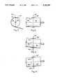
- FIG. 5is a schematic side view illustrating a tiltable roll for adjusting the take-off position of the tow band
- FIG. 8is an elevation view of the roll shown in FIG. 5;
- FIGS. 9 and 10are views similar to FIG. 8, but illustrating the tilting of the roll so as to adjust the lateral position of the tow band to the desired position, i.e., in alignment with another tow band.
- FIG. 11is a plan view of the mechanism for tilting a roll according to this invention.
- FIG. 12is an elevation view of the mechanism shown in FIG. 11.
- an apparatus for producing a layered assembly of bands of materialsuch as ribbon or tow in which the layers are assembled in alignment with each other.
- the apparatusproduces an assembly of bands of generally rectangular cross section having at least two layers of material comprising means for advancing a first band along a predetermined linear path and means for guiding a second band into layered alignment with the first band including a roll around which said second band is partially wrapped prior to contacting said first band, the second band having an initial tangential contact position with said roll along a line on the surface thereof extending generally axially with respect to the roll, the roll being tiltable in a plane defined by the axis thereof and the tangential initial contact position of said second band, whereby the lateral take-off position of the second band may be controlled by tilting said roll so as to guide it into aligned juxtaposition with said first band to form a layered, substantially rectangular tow band.
- the present inventionprovides apparatus for producing a tow band of generally rectangular cross section having at least two layers of filaments in closely adjacent, generally parallel relation comprising
- An important aspect of this inventionis that it is useful in the aligned layering of tow bands, or bands of filaments.
- the apparatus according to this inventionis especially useful in forming a multilayered assembly of tow bands in which a plurality of apparatuses are placed in series to form a multilayered assembly of tow bands in which each layer is accurately aligned with the other layers.
- the filamentsin a generally side-by-side arrangement so that the individual filaments are in a closely adjacent, generally parallel arrangement. It is preferred that the individual filaments actually be touching each other.
- FIG. 1represents a series of apparatuses (3 shown) according to the present invention in which a tow band 10 is being advanced in the direction of the arrow.
- additional tow bands 16 and 18respectively are brought into layered relationship with tow band 10.
- tow band 10normally between 5 and 10 individual bands ("or ends") are brought into layered relationship.
- crimpingsuch as in a conventional stuffer box 20.
- Further processingoften includes wrapping the crimped tow to form a rod, and then cutting the continuous length rod into individual pieces suitable in length for various purposes.
- Each of the tow bands 16 and 18are guided over rolls 21 and 23 at station 12 and 25 and 27 at station 14 respectively.
- Rolls 23 and 27are tiltable rolls in accordance with this invention and are described in detail hereinafter with reference to roll 32 in FIGS. 5 and 8-12.
- tow bands 16 and 18can be precisely aligned with tow band 10 to produce the layered arrangements shown in FIGS. 3 and 4.
- Guide rods 29 and 31 at stations 12 and 14 respectivelyare used to stack the ends in layered relationship.
- FIGS. 2, 3 and 4show cross sections taken along lines 2--2, 3--3 and 4--4 respectively.
- a tow bandconsisting of a single end 10 of adjacent, side-by-side, generally parallel filaments 24 is illustrated. It should be understood that even at this point, the tow band may contain more than 1 layer or end.
- tow bands 16 and 18are placed in layered relationship with tow band 10, as shown in FIGS. 3 and 4. It should be understood that, while three layers are illustrated in FIG. 4, there may be more as additional stations may be used between stations 12 and 14.
- each tow end 10, 16 and 18is directly above the previous one such that the edges thereof generally are in a plane substantially perpendicular to the plane in which the end lies so as to form a rectangular assembly.
- the present inventionis directed to the apparatus which provides for such alignment of the individual ends, and will be described in detail below.
- FIG. 5The apparatus according to this invention, as applied to tow ends for forming tow bands, is illustrated in diagrammatic form in FIG. 5.
- a tow end 30is shown being guided by an "adjustable" godet roll 32.
- godet roll 32can be tilted from its center position shown in FIG. 5 in a clockwise manner to a position as shown in FIG. 9 as represented at changed positions 30' and 32', or counterclockwise to a position such as shown in FIG. 10, as represented by changed positions 30" and 32".
- the maximum amount of possible rotationcan be whatever desired for a particular situation, but normally a maximum arc in both directions, from the center position, of about 5 degrees is sufficient.
- the tilting of roll 32should be in a plane defined by the axis 38 thereof and the tangential initial contact position of the band 34.
- the plane in which roll 32 tiltsis defined by the axis 38 of the roll 30 and a line 34 which is generally the tangential initial contact position of the second band.
- the tow band 30has an initial tangential contact position located generally at 34.
- the other line which defines plane 42, in which roll 32 tilts,is the axis 38 of roll 32.
- FIGS. 8, 9 and 10illustrate the lateral movement of band 30 at the take-off position on roll 32. Centerline 50 is common to each of FIGS. 8, 9 and 10.
- FIG. 9illustrates the lateral offset 50' of band 30' at take-off position when roll 32 is tilted slightly clockwise.
- FIG. 10illustrates the lateral offset 50" of band 30" at take-off position when roll 32" is tilted slightly counterclockwise.
- band 30 wrap roll 32for a circumferential arc of generally 160-180 degrees.
- FIGS. 11 and 12illustrate a preferred apparatus for tilting and supporting roll 32.
- Roll 32is fixed to shaft 60 from electric motor 62.
- Motor 62is mounted to tiltable plate 64 by means of two sets of set and lock bolts 66, 68 and 70, 72 respectively.
- Set bolts 66 and 70serve to allow tilting by turning the bolts in coordination to obtain a particular desired tilt, as they are biased against frame plate 74.
- Lock boltsare threaded into plate 74 and serve to maintain the desired tilt.
- roll 32may be tilted about points 76 and 78 by a simple loosening or tightening of the set and lock bolts on one side (e.g., 66 and 68) with the reverse procedure on the opposite side (70 and 72). This action will tilt the roll 32 in the desired direction as shown in FIGS. 6, 7, 9 and 10 to locate the lateral take off position of the band 30 correctly.
- FIG. 11is a plan view illustrating pivot points 76 and 78 which aid in maintaining alignment of the roll 32.
Landscapes
- Yarns And Mechanical Finishing Of Yarns Or Ropes (AREA)
- Nonwoven Fabrics (AREA)
- Glass Compositions (AREA)
- Laminated Bodies (AREA)
- Registering, Tensioning, Guiding Webs, And Rollers Therefor (AREA)
- Ropes Or Cables (AREA)
- Orthopedics, Nursing, And Contraception (AREA)
- Moulding By Coating Moulds (AREA)
- Reinforced Plastic Materials (AREA)
- Extrusion Moulding Of Plastics Or The Like (AREA)
Abstract
Description
Claims (2)
Priority Applications (9)
| Application Number | Priority Date | Filing Date | Title |
|---|---|---|---|
| US07/923,210US5282294A (en) | 1992-07-31 | 1992-07-31 | Apparatus for producing layered material |
| BR9306807ABR9306807A (en) | 1992-07-31 | 1993-07-26 | Apparatus for producing a strip of generally rectangular cross section having at least two layers |
| AT93918370TATE158231T1 (en) | 1992-07-31 | 1993-07-26 | METHOD FOR PRODUCING A COMPOSITE MATERIAL |
| CA002139936ACA2139936C (en) | 1992-07-31 | 1993-07-26 | Apparatus for producing layered material |
| JP50537794AJP3167727B2 (en) | 1992-07-31 | 1993-07-26 | Equipment for manufacturing laminated materials |
| DE69314037TDE69314037T2 (en) | 1992-07-31 | 1993-07-26 | METHOD FOR PRODUCING A COMPOSITE |
| PCT/US1993/006986WO1994003332A1 (en) | 1992-07-31 | 1993-07-26 | Apparatus for producing layered material |
| EP93918370AEP0652830B1 (en) | 1992-07-31 | 1993-07-26 | Apparatus for producing layered material |
| CN93109314ACN1037947C (en) | 1992-07-31 | 1993-07-31 | Apparatus for producing layered material |
Applications Claiming Priority (1)
| Application Number | Priority Date | Filing Date | Title |
|---|---|---|---|
| US07/923,210US5282294A (en) | 1992-07-31 | 1992-07-31 | Apparatus for producing layered material |
Publications (1)
| Publication Number | Publication Date |
|---|---|
| US5282294Atrue US5282294A (en) | 1994-02-01 |
Family
ID=25448315
Family Applications (1)
| Application Number | Title | Priority Date | Filing Date |
|---|---|---|---|
| US07/923,210Expired - LifetimeUS5282294A (en) | 1992-07-31 | 1992-07-31 | Apparatus for producing layered material |
Country Status (9)
| Country | Link |
|---|---|
| US (1) | US5282294A (en) |
| EP (1) | EP0652830B1 (en) |
| JP (1) | JP3167727B2 (en) |
| CN (1) | CN1037947C (en) |
| AT (1) | ATE158231T1 (en) |
| BR (1) | BR9306807A (en) |
| CA (1) | CA2139936C (en) |
| DE (1) | DE69314037T2 (en) |
| WO (1) | WO1994003332A1 (en) |
Cited By (1)
| Publication number | Priority date | Publication date | Assignee | Title |
|---|---|---|---|---|
| US5860201A (en)* | 1993-06-16 | 1999-01-19 | Rhodia Acetow Aktiengesellschaft | Multiple width fiber strip and method and apparatus for its production |
Families Citing this family (1)
| Publication number | Priority date | Publication date | Assignee | Title |
|---|---|---|---|---|
| JP6109642B2 (en)* | 2013-05-21 | 2017-04-05 | ダンロップスポーツ株式会社 | Golf club head |
Citations (8)
| Publication number | Priority date | Publication date | Assignee | Title |
|---|---|---|---|---|
| US2346258A (en)* | 1941-06-13 | 1944-04-11 | Du Pont | Method for production of cellulose acetate staple |
| US3277537A (en)* | 1964-03-02 | 1966-10-11 | Du Pont | Yarn guide for shaping tow |
| US3452410A (en)* | 1965-06-04 | 1969-07-01 | Courtaulds Ltd | Process of opening and crimping tow |
| US3526350A (en)* | 1968-05-03 | 1970-09-01 | Hood Co R H | Tow director |
| US3763520A (en)* | 1971-09-02 | 1973-10-09 | Teijin Ltd | Methods and apparatus for transferring tows |
| US4556208A (en)* | 1984-08-06 | 1985-12-03 | Harris Graphics Corporation | Web skewing apparatus |
| US5018267A (en)* | 1989-09-05 | 1991-05-28 | Armco Inc. | Method of forming a laminate |
| US5146651A (en)* | 1990-12-21 | 1992-09-15 | E. I. Du Pont De Nemours And Company | Process and apparatus for tow cross-section measurement and control |
Family Cites Families (5)
| Publication number | Priority date | Publication date | Assignee | Title |
|---|---|---|---|---|
| CA639824A (en)* | 1952-12-05 | 1962-04-17 | B. Stevens Joel | Filter tow treated with sorbitan compounds |
| US2941572A (en)* | 1957-05-06 | 1960-06-21 | Eastern Corrugated Container C | Edge aligning means for travelling combining webs |
| US3244340A (en)* | 1963-09-30 | 1966-04-05 | Fife Mfg Company Inc | Apparatus for maintaining the alignment of a moving web |
| GB1463114A (en)* | 1974-01-28 | 1977-02-02 | Rothmans Of Pall Mall | Method and apparatus for the opening of tow |
| US4288273A (en)* | 1980-05-12 | 1981-09-08 | Butler Greenwich Inc. | Method and apparatus for making corrugated board |
- 1992
- 1992-07-31USUS07/923,210patent/US5282294A/ennot_activeExpired - Lifetime
- 1993
- 1993-07-26JPJP50537794Apatent/JP3167727B2/ennot_activeExpired - Fee Related
- 1993-07-26BRBR9306807Apatent/BR9306807A/ennot_activeIP Right Cessation
- 1993-07-26CACA002139936Apatent/CA2139936C/ennot_activeExpired - Fee Related
- 1993-07-26ATAT93918370Tpatent/ATE158231T1/ennot_activeIP Right Cessation
- 1993-07-26DEDE69314037Tpatent/DE69314037T2/ennot_activeExpired - Fee Related
- 1993-07-26WOPCT/US1993/006986patent/WO1994003332A1/enactiveIP Right Grant
- 1993-07-26EPEP93918370Apatent/EP0652830B1/ennot_activeExpired - Lifetime
- 1993-07-31CNCN93109314Apatent/CN1037947C/ennot_activeExpired - Fee Related
Patent Citations (8)
| Publication number | Priority date | Publication date | Assignee | Title |
|---|---|---|---|---|
| US2346258A (en)* | 1941-06-13 | 1944-04-11 | Du Pont | Method for production of cellulose acetate staple |
| US3277537A (en)* | 1964-03-02 | 1966-10-11 | Du Pont | Yarn guide for shaping tow |
| US3452410A (en)* | 1965-06-04 | 1969-07-01 | Courtaulds Ltd | Process of opening and crimping tow |
| US3526350A (en)* | 1968-05-03 | 1970-09-01 | Hood Co R H | Tow director |
| US3763520A (en)* | 1971-09-02 | 1973-10-09 | Teijin Ltd | Methods and apparatus for transferring tows |
| US4556208A (en)* | 1984-08-06 | 1985-12-03 | Harris Graphics Corporation | Web skewing apparatus |
| US5018267A (en)* | 1989-09-05 | 1991-05-28 | Armco Inc. | Method of forming a laminate |
| US5146651A (en)* | 1990-12-21 | 1992-09-15 | E. I. Du Pont De Nemours And Company | Process and apparatus for tow cross-section measurement and control |
Cited By (1)
| Publication number | Priority date | Publication date | Assignee | Title |
|---|---|---|---|---|
| US5860201A (en)* | 1993-06-16 | 1999-01-19 | Rhodia Acetow Aktiengesellschaft | Multiple width fiber strip and method and apparatus for its production |
Also Published As
| Publication number | Publication date |
|---|---|
| ATE158231T1 (en) | 1997-10-15 |
| JPH08501032A (en) | 1996-02-06 |
| EP0652830A1 (en) | 1995-05-17 |
| WO1994003332A1 (en) | 1994-02-17 |
| JP3167727B2 (en) | 2001-05-21 |
| DE69314037D1 (en) | 1997-10-23 |
| DE69314037T2 (en) | 1998-01-22 |
| CA2139936C (en) | 1999-01-05 |
| CN1087052A (en) | 1994-05-25 |
| CN1037947C (en) | 1998-04-08 |
| BR9306807A (en) | 1998-12-08 |
| CA2139936A1 (en) | 1994-02-17 |
| EP0652830B1 (en) | 1997-09-17 |
Similar Documents
| Publication | Publication Date | Title |
|---|---|---|
| US5695105A (en) | Apparatus for cutting a web at a predetermined length and supplying the same | |
| US3145429A (en) | Apparatus for combining a plurality of ribbon-like filament bundles into a single sheet of filaments | |
| EP3093381B1 (en) | Method and apparatus for manufacturing bloomed fiber material | |
| US4301579A (en) | Widening-narrowing guide for textile filament bundle | |
| DE102013211809A1 (en) | Device for pulling spun thread from melt-spinning and receiving device, has rollers adjacently formed in direction, in which thread runs, where non-contact length of part of thread is smaller than contact length of part of thread | |
| JPH0477239A (en) | Method and apparatus for molding cord-containing rubber sheet | |
| US3146512A (en) | Crimping apparatus | |
| US3664115A (en) | Method of making a semi-continuous filament combination yarn | |
| US3796035A (en) | Semi-continuous filament combination yarn | |
| US5282294A (en) | Apparatus for producing layered material | |
| US4989799A (en) | Apparatus for winding a multifilament with flat shape and broad width | |
| JP2652844B2 (en) | Multi-width fiber strip, and method of manufacturing the same and apparatus for performing the method | |
| US3417560A (en) | Method and apparatus for producing a semi-continuous filament yarn | |
| US3763520A (en) | Methods and apparatus for transferring tows | |
| KR910008541B1 (en) | Method of manufacturing a flat bibbon-shaped coil | |
| DE3787311T2 (en) | False twisting device. | |
| US5683777A (en) | Multiple width fiber strip and method and apparatus for its production | |
| US3444683A (en) | Manufacture of endless threadlike products of thermoplastic materials | |
| US4293518A (en) | Control of synthetic yarns during drawing with heated rolls | |
| US4247270A (en) | Apparatus for the continued manufacture of staple fibers from thermoplastic materials | |
| US3798718A (en) | Apparatus for stuffer-crimping yarn | |
| CN88102189A (en) | Splice and the device used of winding slivers | |
| KR100542480B1 (en) | Spin draw winder | |
| US3238591A (en) | Yarn twist control apparatus and method | |
| US4499639A (en) | Process for broadening the width of a bundle of parallel filaments having a band form |
Legal Events
| Date | Code | Title | Description |
|---|---|---|---|
| AS | Assignment | Owner name:EASTMAN KODAK COMPANY, NEW YORK Free format text:ASSIGNMENT OF ASSIGNORS INTEREST.;ASSIGNORS:SPALLER, ALBERT E., JR.;CARTER, WHITNEY B.;HORNE, FRED W.;AND OTHERS;REEL/FRAME:006284/0157 Effective date:19920911 | |
| FEPP | Fee payment procedure | Free format text:PAYOR NUMBER ASSIGNED (ORIGINAL EVENT CODE: ASPN); ENTITY STATUS OF PATENT OWNER: LARGE ENTITY | |
| STCF | Information on status: patent grant | Free format text:PATENTED CASE | |
| CC | Certificate of correction | ||
| AS | Assignment | Owner name:EASTMAN CHEMICAL COMPANY, TENNESSEE Free format text:ASSIGNMENT OF ASSIGNORS INTEREST;ASSIGNOR:EASTMAN KODAK COMPANY;REEL/FRAME:007115/0776 Effective date:19940223 | |
| FEPP | Fee payment procedure | Free format text:PAYOR NUMBER ASSIGNED (ORIGINAL EVENT CODE: ASPN); ENTITY STATUS OF PATENT OWNER: LARGE ENTITY Free format text:PAYER NUMBER DE-ASSIGNED (ORIGINAL EVENT CODE: RMPN); ENTITY STATUS OF PATENT OWNER: LARGE ENTITY | |
| FPAY | Fee payment | Year of fee payment:4 | |
| FPAY | Fee payment | Year of fee payment:8 | |
| FPAY | Fee payment | Year of fee payment:12 | |
| SULP | Surcharge for late payment | Year of fee payment:11 |